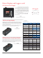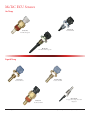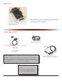
1
July 2012 MoTeC Systems USA 5355 Industrial Drive Huntington Beach, CA 92649 1.800.845.7580 1.714.897.8782 fax [email protected] 2012 Catalog Revision 3a MoTeC Systems East 169-5 Gasoline Alley Mooresville, NC 28117 1.704.799.3800 1.704.799.3874 fax [email protected] MoTeC Systems West Optimal performance begins here. Stop by and see us in Huntington Beach, California. We’ve been providing the best in engine-management systems and support since 1985. Business Hours: Monday - Friday 8:30am - 5:00pm Page Engine Management and Data Acquisition Systems MoTeC Systems East 169-5 Gasoline Alley Mooresville, NC 28117 (704) 799-3800 Business Hours: Monday - Friday 8:30am - 5:00pm Phone (714) 895-7069 • Fax (714) 230-3076 • www.motec.com Page Table Of Contents MoTeC Systems West MoTeC Systems East MoTeC Steering Wheels Driver Displays and Loggers 2 3 8 9 Driver Display & Logger Options/Upgrades 9 Sports Dash 3 Advanced Dash Logger (ADL3) 9 9 Sport Dash Upgrades ADL3 Upgrades CDL3 Upgrades 9 9 9 Driver Displays and Loggers con’d 10 Club Dash Logger 3 (CDL3) Features Accessory Kit Additional Looms Optional features 10 10 10 10 10 Inputs Outputs Compatibility 10 10 10 Driver Displays and Loggers con’d 11 Professional Lambda Meter Accessories Professional Lambda Meter 12 12 MoTeC Mini Display Dash Expansion Boxes 13 13 ACL (Advanced Central Logger) VIM (Versatile Input Module) SVIM (Synchronous Versatile Input Module) ACL Upgrades 11 11 11 11 Specifications: 12 MoTeC Mitsubishi Diff Controller MoTeC Ignition Expander IGN EX / TC MUX Harness Spares MoTeC Traction Control Multiplexer Did You Know? MoTeC Traction Control Multiplexer 14 14 14 14 14 MoTeC ECU’s MoTeC ECU Comparison Chart MoTeC M800 Plug & Play ECU (OEM) 15 16 17 MoTeC Beacon Transmitter and Receiver MoTeC ADL Hardware 18 18 Video 19 MoTeC ECU Options 17 Billet Shift / Warning Indicator Acceleration/Yaw 18 18 VCS Video Capture System VSM – Video Sync Module 19 19 GPS Receivers 20 RaceGrade GPS Page 20 Engine Management and Data Acquisition Systems MoTeC GPS 20 Capacitive-Discharge Ignitions Capacitive-Discharge Ignitions Accessories 21 21 Capacitive-Discharge Coils CDI-8 Wiring Multi Coil Inductive Coil-Near Plug Inductive Denso Termination 21 21 21 22 22 Like Thunder and Lightning 22 Multi-Channel Ignitors Power Supply 23 Why Do I need an Ignitor - what do they do? Why doesnt the MoTeC have a built in ignitor? 23 23 24 Power Distribution Modules Dual Half Bridge (DHB) Fluid Level Sensor String Potentiometers Ride Height Sensors Steering-Wheel Switch Assembly 24 24 24 25 25 25 MoTeC Hardware 26 MS Switches 26 Silicone Switch Covers Emergency Switches 26 26 Linear Position Sensors Aerodynamics 27 27 Engine Hardware 28 Trigger Wheels Dual Magnetic Converter (DMC) Sensors 28 28 Magnetic Sensor Amplifiers 28 29 Crank/Cam Trigger 29 Mag Sensor Polarity 29 Rising or Falling edge? Missing Tooth / Mag Sensor Falling Edge Polarity Mag Sensor Rising Edge Polarity Pole Diameter Fuel Delivery Regulator Fittings Controls 30 30 30 30 31 31 How big of a Pump do I need? 31 32 Air Control Valves Trim Switches 32 32 Boost Control has never been easier How can I use a Trim Switch? 32 32 Wheel Speed 33 Manifold Pressure Sensors 34 Calibrating Wheel Speeds 33 How to Calibrate a Pressure Transducer 34 MoTeC Sensors 35 Sensors 36 Pressure Sensors Pressure-Sensor Unions Phone (714) 895-7069 • Fax (714) 230-3076 • www.motec.com 35 35 Page Throttle Angle Lambda Sensors 36 37 What is Lambda anyway? How long will the Lambda Sensor Last? 37 37 MoTeC ECU Sensors 38 Plug-and-Play Basic or Custom-Made MoTeC ADL2 Hardware 40 40 ADL / ADL2 / SD Harnesses MoTeC ADL Hardware 41 41 MoTeC Wiring 42 Air Temp Liquid Temp Head Temp Exhaust Temp 38 38 39 39 Custom ADL2 Harnesses 40 Basic Harness Harness Extensions 41 41 ECU Harnesses Unterminated, Trim-to-Length Harnesses Full-Custom Harness 42 42 43 Steps to build your Custom Harness 43 Heat Resistant Sheathing Update Units Comm Cables ECU-PC 43 44 44 Comm Cables ECU-PC, cont. MoTeC USB To CAN Adapter MoTeC Lambda to CAN Adapter MoTeC STC (Serial to CAN) Adapter 45 45 45 45 What is an M4e? M4e Comms Pinout Note: M4 ECU’s with serial number greater than 3000 do not require SUU to upgrade! Wiring and Related Diagnosis and Testing 44 44 44 46 47 MoTeC Comms Tester and Power Up Harnesses 47 Comms Tester for M4/M4e/M48 ECU’s 47 MoTeC Break-Out Harnesses 47 Crimping Tools Crimping Tools Crimping Tools Extractor Tools MAP Sensor Connector Kits 48 49 50 51 52 Weather-Pack 53 Weather-Pack, cont. Metripack Metripack, cont. Miscellaneous 54 54 55 55 Miscellaneous, cont. DTM Kits 56 57 Tester for M400/600/800 47 MAP Sensor Connector Colors 52 A word about Weatherpack 53 Pull to Seat Style Page 55 Engine Management and Data Acquisition Systems DT Kits DTP Kits Bosch Sensors Boots Vinyl Boots 58 58 59 60 60 Autosport Connectors 61 Apparrel MoTeC Support 68 69 Micro Series Micro Series con’d Micro Series con’d AS Series AS Series con’d AS Series con’d AS Series con’d 61 62 63 64 65 66 67 On-site support Phone support Track-support packages 69 69 69 Online Help Files 69 MoTeC Glossary Phone (714) 895-7069 • Fax (714) 230-3076 • www.motec.com 70 Page MoTeC Steering Wheels Made from 6061-T6 aluminum the MDD-SW housing is rugged enough to handle any motorsport use. It communicates with the MoTeC ADL or M800 ECU via CAN. The MDD-SW controls 12 LED outputs, and handles 12 switch inputs. The Mini-Display-Dash currently fits the following models: M MDD 12-1 Momo model 12 M MDD 27-1 Momo model 27 M MDD 29-1 Momo model 29 For options list and ordering please consult your MoTeC Representative Laser Etched Graphics 4-way Switches You can order your MDD-SW completely customized with your team’s logo or driver’s signature on it. Our laser can also label buttons and controls so the driver never forgets what button to push. You can choose a 4 way multiple switch to replace any of the buttons. This provides a variable voltage input device. Configurable LCD Read Out The LCD display features adjustable brightness and contrast controls. In lap mode, it features a Gain/Loss bar graphic and switch to an “ADL display mode” to mimic the ADL dash display. Pit Lane Speed Control The Pit lane speed button latches on with one push. The top LED’s switch from green to red, counting down your speed. When you’re leaving the pits, push it once more to turn it off. Page L.E.D. Lights The MDD-SW features bi-color, high intensity LED’s used for shift lights, warning lights, and pit lane speed. Additional Buttons The base MDD-SW comes with 4 buttons. You can add up 12 buttons, available in a multiple of colors and labels, to suit driver’s preference. Additional Models Coming Soon... Engine Management and Data Acquisition Systems Driver Displays and Loggers Sports Dash 3 The Sport Dash Logger (SDL3) comes standard as a combined display and powerful control device in one lightweight unit. With the addition of the Data Logging upgrades it becomes a fully programmable data logger with 16 or 120 MB memory. It offers the same construction and advanced technology as the top of the line ADL3, with a package of features tailored to more moderate system requirements. The display layout is fully configurable to show a multitude of data channels, warning alarms, lap times, fuel calculations, minimum corner speeds, maximum straight speeds and more. Four auxiliary outputs are available to control external devices. With the use of an E888 expander, eight additional thermocouple outputs are available, making this versatile unit suitable for many applications. M SDL3 Sport Dash 3 M SDL3 BL Sport Dash 3 with Back Light Option** Advanced Dash Logger (ADL3) MoTeC’s Advanced Dash Logger (ADL3) is a combined display, fully programmable data logger and powerful control device, all in one lightweight unit. It is a flexible, professional level system that is designed to grow with you as your requirements increase. As standard, the ADL3 comes with 16 MB of data logging, which can be upgraded to 250 MB at any time. The ADL3’s screen layout is fully configurable to display a multitude of data channels, warning alarms, lap times, fuel calculations, minimum corner speeds, maximum straight speeds and more. Four auxiliary outputs can be used to control external devices with additional outputs available as an upgrade or created by using expander modules. MoTeC’s i2 data analysis software provides all the tools for comprehensive analysis of logged data, and a telemetry option is available for real time viewing of data while the vehicle is on the track. M ADL3 MoTeC ADL3 Data Logger M ADL3 BL MoTeC ADL3 Data Logger with Back Light Option** Driver Display & Logger Options/Upgrades Sport Dash Upgrades ADL3 Upgrades CDL3 Upgrades Add an additional 16MB of Logging Memory Add an additional 250MB of Logging Memory Add an additional 8 MB of Logging Memory Go from 16MB to 120MB of Logging Memory Add additional I/O for a total of 52 I/O 12 I/O Upgrade Pro Analysis Pro Analysis Remote Logging Telemetry ** Back Light Option must be stated at the time of purchase Phone (714) 895-7069 • Fax (714) 230-3076 • www.motec.com Page Driver Displays and Loggers con’d Club Dash Logger 3 (CDL3) The Club Dash Logger (CDL3) comes standard as a combined backlit display and powerful control device in one lightweight unit. With the addition of the Data Logging upgrade it becomes a fully programmable data logger with 8MB memory. It offers the same construction and advanced technology as the top of the line ADL3, with a package of features tailored to entry level motorsport requirements. The screen layout is fully configurable to display a multitude of data channels, warning alarms, lap times, fuel calculations, minimum corner speeds, maximum straight speeds and more. The CDL3 performs calculations, acquiring data from other devices such as an ECU. Features • All-in-one display, logger* and controller* • Suitable for bikes, cars, marine and industrial applications • Compact, durable and reliable unit • Supports Wideband Lambda from MoTeC PLMs or LTCs • Easily integrates with MoTeC CAN-based expanders, GPS, shift lights and ECUs Optional features Accessory Kit M CDL3 BL Club Dash Logger Backlit Inputs • 4 x Analogue voltage high resolution inputs • 2 x Analogue temperature inputs • 2 x Digital inputs • 3 x Speed inputs with voltage measuring capability • Compatible with E888 expander (8 Thermocouples only) Club Shift Light Module CDL3 Wiring Loom Outputs • 4 x PWM, switched or digital outputs Logging • 8 MB logging memory • Logging rates up to 500 samples per second • Fast Ethernet download Additional Information Compatibility 2 Button Loom M CDL3 ACC KIT CDL3 ACCESSORY KIT 10Hz GPS • MoTeC ECUs: M4, M48, M8, M84, M400, M600, M800 and M880 • MoTeC Accessories: MDD, E888, SLM, PLM, LTC, BR2, PDM, GPS, VCS etc. • Many non-MoTeC devices Additional Looms M CDL3 OBDII ADP M CDL3 MX00 ADP M CDL3 M4 ADP M H CDL3 I/O EXP M CDL3 CURLY EXT A terminated OBD-II loom that connects the CDL3 kit loom to a vehicle’s OBD-II port with no other wiring required. CDL3 to OBD-II This loom lets a user install the CDL3 kit into their M400/M600/M800/M84 equipped car without requiring custom wiring. CDL3 to CAN ECU For users with RS232 based ECUs you can plug this loom into your D9 download cable, and the other into your CDL3 loom ECU connector to get data from your ECU. CDL3 to RS232 ECU When combined with the CDL3 I/O upgrade (M CDL3 12 I/O), this loom adds 6 Inputs to your CDL3 loom in a simple, easy to install fashion. CDL3 I/O Loom The terminated curly cord allows the CDL3 Kit buttons to be moved onto the steering wheel with ease. Terminated Curly Cord Page 10 Engine Management and Data Acquisition Systems Driver Displays and Loggers con’d ACL (Advanced Central Logger) The ACL performs data logging, data communications and sophisticated calculations, as well as acquiring sensor data via the VIM expander modules. It also collects data from other connected devices such as MoTeC ADL2, SDL or ECU. The ACL has a very large logging capacity (1GB+) with fast download via an Ethernet connection. It provides all the advanced features of MoTeC ’s ADL2 Dash Logger, including warning alarms, fuel prediction, engine logs, timers, tables, user conditions, telemetry and more. A remote display device such as MoTeC’s MDD, ADL2 and SDL can also be connected, as well as the SLM (Shift Light Module) ACL Upgrades Add Telemetry Add Remote Logging Add Pro Analysis M ACL Advanced Central Logger w/Pro Analysis VIM (Versatile Input Module) The VIM is a compact and versatile input expander module with high resolution inputs. Multiple VIMs may be connected to the ACL Central Logger via a two wire CAN connection, allowing for more than 200 sensor inputs. The distributed nature of the VIMs wired onto the CAN bus allows them to be located close to the connected sensors, minimizing wiring complexity and weight. It has 24 Analog inputs of various types including eight differential inputs with programmable gain which are suitable for strain gauges and isolated thermocouples. Key: - standard available - not available option - requires optional upgrade Data Acquisition Comparison Table SDL3 ADL3 / EDL3 ACL Analogue voltage 8 10 via VIM, SDL, E888, E816 Analogue temperature 4 Digital 2 4 Inputs M VIM Versitile Input Module optional 24 4 optional 8 via SDL via VIM, SDL, E888, E816 Speed 2 4 via VIM, SDL Switch 4 via SDL, E888, E816 Wideband Lambda via PLM or LTC via PLM or LTC via PLM or LTC E888; up to 2 x VIM up to 8 x VIM 8 thermocouples and 2 x and 2 x only E888/E816 E888/E816 Data logging memory optional 8 MB or 120 MB optional 250 MB Logging rate 1 - 500 Hz 1 - 1000 Hz 1 - 5000 Hz Analysis using i2 Standard option Analysis using i2 Pro option option Telemetry option option Remote logging option option Reflective LCD Expansion units Data acquisition and telemetry SVIM (Synchronous Versatile Input Module) The new SVIM shares similar features with the VIM but is precisely synchronised, acquiring data of the highest integrity for use in advanced chassis and suspension analysis. It samples its eighteen 15 bit inputs at the same instant using 18 separate converters with fifth order anti-aliasing filters. The filters ensure that signals can be properly reconstructed to use in calculations such as FFT (Fast Fourier Transform). 16 MB 1 GB Display Backlight Display modes option 3 on ADL3 on EDL3 option on ADL3 on EDL3 3 on ADL3 on EDL3 via SDL, MDD via SDL, MDD 3 via SDL Communications CAN 2 2 2 RS232 RS422, RS485 Ethernet Digital, Switched, PWM 4 M SVIM Synchronous Versatile Input Module PC connection Outputs Expansion units Phone (714) 895-7069 • Fax (714) 230-3076 • www.motec.com 4 optional 8 via E888, E816 1 or 2 x E888/E816 1 or 2 x E888/E816 SDL3 ADL3 / EDL3 ACL Page 11 Professional Lambda Meter T he MoTeC Professional Lambda Meter (PLM) determines exhaust gas mixture strength over a wide range of conditions with a fast response time. Quick and easy to use, it allows a calibration engineer all the power and configurability required for OE emissions development and certification work. T he MoTeC PLM provides a differential analog-voltage output that connects to an analog meter or measurement instrument such as data logger or chart recorder. Define output as linear or non-linear in relation to the measured units. The PLM also supports 1mbit CAN and RS232 data links to devices such as the MoTeC dash/logger for transmission of sensor and diagnostic data. Comprehensive diagnostic, status channels are provided for. T he PLM can be used as Lambda input for an ECU!. Instead of purchasing the Lambda Upgrade on M4/M48 - the PLM’s definable output voltage can be used as the input for Lambda on these ECU’s. This gives you the use of a more state of the art sensor with a digital display which you can place on your dashboard for viewing even if the ECU is offline. Of course you can then use this lambda meter on any other car you wish. Specifications: • Weighs135 gms • Robust aluminum enclosure • Operating range 0.70 and 32.0 lambda (for gasoline/petrol this equals air/fuel ratio range of 10.3:1 to 470:1) • Display lambda, air/fuel ratio, or oxygen percentage for any sensor-compatible fuel • Define display resolution (in decimal points), update rate, filtering, backlight intensity • Easy Air calibration using PLM Software (no twisting of screws or watching LED’s required) M PLM Professional Lambda Meter Kits come with Sensor, Harness, Software, O2 Bung, Comm Cable and Users Manual Professional lambda meter with Bosch LSU lambda sensor or NTK Pro Uego lambda sensor. Professional Lambda Meter Accessories M PLM CIG Cigar Lighter Adapter Allows you to power the PLM from a car cigar lighter - great for in-car tuning. TR-18 PLUG 18mm X 1.5mm threaded stainless bung, with copper washer. TR-18-13 18mm SS Ring for LSU Sensor. TR-18 SS Oxy Sensor Ring 304L Stainless PLM Universal Mounting Kit PLM Suction Cup M PLM MOUNT M PLM SUCT CUP Use the PLM Suction Cup with the PLM Universal Mounting Kit to mount your PLM to your windshield. Page 12 M PLM EXT PLM Extension Cable Connects between PLM and Serial Port on PC. Adds 20 feet of length between PLM and existing harness connector Used to lengthen any PLM Harness regardless of sensor type. Rugged design is impervious to oil - excellent for dyno rooms and boats. Engine Management and Data Acquisition Systems MoTeC Mini Display Dash Expansion Boxes M E888 M MDD-1 Mini Dash Display The display is a DOT Matrix backlit graphics LCD which allows the MDD to support a number of different display layouts to suit various applications. The MDD is small enough to be mounted on the steering wheel or it may be mounted in a more traditional location using 2 sided tape or Velcro. The MDD and its outputs are fully controllable when the MDD is used in conjunction with the ADL. When used with an ECU, the MDD features predefined display screens. A Switched input to the MDD allows the user to toggle through the different display screens on the MDD. • Weighs120 gms (1/4 pound) • Robust aluminum enclosure • W X L X H = 3.38 X 2.34 X .86 inches • Max Current Requirement 150mA @14volts • For use with ADL Dash Logger or with a MoTeC ECU • Receives data via serial or CAN bus E888 and E816 add additional I/O to your system. They talk to the Dash over the CAN bus so only 2 wires must be routed to the dash from either the E888 or E816. Each device features its own 0v and 5v references to monitor its own sensor inputs. E888 contains: - 8 Thermocouple inputs - 8 Analog Voltage inputs - 4 Digital Inputs - 2 Switched Inputs - 2 Cold Junction Compensation Inputs - 8 PWM Outputs Option - Integrated Switch Assembly M E816 E816 Contains: - 16 Analog Voltage Inputs - 4 Digital Inputs - 2 Switch Inputs - 2 Thermistor Inputs - 8 PWM Outputs Phone (714) 895-7069 • Fax (714) 230-3076 • www.motec.com Page 13 MoTeC Mitsubishi Diff Controller The Mitsubishi Diff Controller (MDC) is a direct replacement for the Active Centre Diff (ACD) controller for the EVO 7, 8 and 9 models. The MDC is a fully programmable centre diff controller. Six different diff control mode are selectable from the standard ACD button located on the dash board. The modes include 0% and 100% lock and four user programmable modes. The MDC can be used on vehicles fitted with Active Yaw Control (AYC) but the AYC will be disabled. M MDC Mitsubishi Diff Controller MoTeC Ignition Expander MoTeC Traction Control Multiplexer The MoTeC Ignition Expander enhances the ignition control capability of any MoTeC ECU . The MoTeC IEX will allow a single MoTeC ECU output to control up to 8 individual coil drivers. The MoTeC Traction Control Multiplexer goes between the ECU and the wheel speed sensors It gathers the speed information from the 4 wheels and calculates the ground speed from the fastest rolling wheel and speed difference from the driven wheels. The MoTeC Traction Control Multiplexer is very useful in allowing 4 separate speed channels to be brought into one input of the ECU M IGN EX M TC MUX Did You Know? The MoTeC ECU software will not let you perform an ignition test while using the ignition expander. However you can easily make a jumper and change the ignition setup in the software to 1 coil. Then you can go into the ignition test screen, and use the jumper on the harness at the Expander connector (Expander unplugged) and test each coil Output. IGN EX / TC MUX Harness Spares MoTeC Traction Control Multiplexer M ECONO 18 18-way plug set for M IGN EX and M TC MUX Page 14 Engine Management and Data Acquisition Systems MoTeC ECU’s M84 M400 M820 Phone (714) 895-7069 • Fax (714) 230-3076 • www.motec.com M600 M880 Page 15 MoTeC ECU Comparison Chart These are the main specifications of the MoTeC ECU range to compare the suitability of the different models for your application. standard available not available option - requires optional upgrade ECU Comparison Table Number of cylinders M2R MLS M4 M48 M84 M400 M600 M800 M880 Sequential up to 4 up to 4 up to 4 up to 8 up to 8 up to 4 up to 6 up to 8 opt 12 up to 12 2 up to 12 2 up to 12 2 up to 12 2 up to 8 2,3,4 up to 4 2 up to 6 2,3 up to 12 2,3,4 up to 8 opt 12 up to 12 2,3,4 4 up to 4* up to 4* 4 up to 4* up to 4* 4 up to 4* up to 4* 8 up to 2* up to 4* 8 6 8 4 4 8 6 6 8 8* 6* 8 8* 6* 8 Group fire mode Rotary Outputs Injector outputs Ignition outputs Auxiliary outputs Option to use spare outputs as auxiliary outputs Individual cylinder tables option option option Inputs Trigger inputs (Ref/Sync) Analogue voltage inputs 2 3 2 3 2 3 2 3 2 8 2 8 2 8 2 8 2 8 Analogue temperature inputs 3 3 3 3 3 6 6 6 6 Digital/speed inputs Wideband Lambda inputs 2 2 2 2 4-wire (option) 4-wire (option) 4-wire (option) 4-wire (option) 512 kB 512 kB 512 kB 512 kB 20 Hz 20 Hz 20 Hz option option (option) Communication RS232 CAN Data acquisition and telemetry Data logging (option) Maximum logging rate Track mapping Data analysis using i2 Pro Telemetry Remote logging Functions and features Boost control Nitrous Injection Dual stage injection (Hi/Lo injection) Ground speed limiting Traction and launch control Overrun boost enhancement (anti-lag) Gear change ignition cut (flat shifts) Stepper motor idle control Continuously variable camshaft control Drive by wire throttle control Servo motor control Page 16 4 4 4 4 4 2 x 5-wire (single 1 x 5-wire 2 x 5-wire 2 x 5-wire 2 x 5-wire included, dual (option) (option) (option) (option) option) 512 kB 512 kB 1 MB 1 or 4 MB 20 Hz 512 kB included 100 Hz 200 Hz 200 Hz 200 Hz 200 Hz option option option option option option option option option option option option option option option option option option option option option option option option option option option option option option option option option option option option option option option option option option option option option option option option option option option option option Engine Management and Data Acquisition Systems MoTeC M800 Plug & Play ECU (OEM) Also available amongst MoTeC’s wide range of engine management options are the discreet M800 Plug & Play systems. These ECUs are designed as plug in boards to replace the OEM computers in a number of high performance late model vehicles. These units provide the flexibility and performance of a MoTeC M800 ECU without the necessity of rewiring the car or building adapter looms. M800 Plug & Play ECUs are built with the same options as a standard M800, though there are some limitations due to factory plug designs. To assist with the tuning of your vehicle they can also be supplied with a start up engine map. Currently available are: M800-EVO 4-8 - M800 OEM ECU FOR EVO 4-8 M800-EVO8GSR - M800 OEM ECU FOR EVO EVO8GSR M800-EVO9 - M800 OEM ECU FOR EVO 4-7 AND EVO9 M800-WRX7 - M800 OEM ECU FOR WRX7 M800-WRX9 - M800 OEM FOR WRX V9/10 M800-EVO X- M800 OEM ECU FOR EVO X MoTeC ECU Options Description OEM M2R MLS M4 M48 = Available M84 512K DATALOG M400/M600 ENABLE 1 MEG INT LOGGING M400 M600 M820 M880 ADD 3 MEG INT LOGGING ENABLE SINGLE WIDE LAMBDA ENABLE UPGD SNGL TO DUAL LAM ENABLE DUAL WIDE LAMBDA ENABLE ADVANCED FUNCTIONS ENABLE ACTIVE CAM CONTROL ENABLE DRIVE BY WIRE ENABLE OVERRUN BOOST EN 10/12 CYL OPERATION ENABLE MULTIPULSE FUNCTIONS ENABLE PRO ANALYSIS ENABLE REMOTE LOGGING ENABLE DC SERVO OPERATION ENABLE TELEMETRY OUTPUT ENABLE GEAR CHANGE IGNITION CUT ENABLE HI-LO INJECTION ENABLE TRACTION CONTROL Phone (714) 895-7069 • Fax (714) 230-3076 • www.motec.com Page 17 MoTeC Beacon Transmitter and Receiver Transmitters and receivers offer 1,000 different codes, to avoid conflicts with competitors’ beacons. To change channels on the transmitter, simply open the cover by removing the screws and adjust the dip switch inside to the desired channel. The BR-2 can be configured using the Dash Manager software and the Beacon Configuration Utility which comes with Dash Manager. M ADL BTX 1,000-channel IR beacon transmitter Includes cable, angle bracket for 1/4² camera mount. Transmitter sets up on the track. M ADL BRX-2 Beacon Reciever 2 - Autosport microterm connector CAN capable with increased accuracy MoTeC ADL Hardware Billet Shift / Warning Indicator CAN based Shift Light Modules. Each LED is fully independent as to the purpose and the same light can be used for multiple functions. M SLM With a flat base M SLM USA With an angled base Acceleration/Yaw M ADXL-1 Accelerom. 4G, one axis, with DTM connection Page 18 M YAW 100 M YAW 200 Engine Management and Data Acquisition Systems Video VCS Video Capture System MoTeC’s VCS Video Capture System is an integrated in-car camera system, designed for race cars and other harsh environments. The VCS is supplied as a kit (see next page) with either a 4 GB or 16 GB high performance flash card. Features: · · · · · · · · · · · Solid state digital recorder MPEG-2 video compression format at broadcast quality Configurable two camera PIP - Picture In Picture - system (second camera optional) Uses 12 V vehicle power - no recharging CAN interface for easy connection to MoTeC Data Loggers and ECUs Video can be linked to logged data using MoTeC’s i2 Pro Data analysis software* Footage can be automatically synchronised to the logged data using the VSM (optional) Programmable Auto Start/Stop Recording using any transmitted channel Gauges are recorded live on the video Fast USB2 download - no bent card pins Customisable screen layout Kit Includes M VCS With 4GB memory card M VCS 16 With 16GB memory card Recorder · VCS Pro Recorder, 4 GB card or · VCS Pro Recorder, 16 GB card Camera and Microphone · Camera · Microphone Looms and Cable · Mini-USB B to USB A Male Cable · VCS Adapter Loom · VCS Power / CAN Loom Mounts · Roll Cage Mounting Bracket · VCS Mounting Plate VSM – Video Sync Module MoTeC’s Video Capture System (VCS) is an integrated in-car camera system, designed and built for race cars and harsh environments. The VCS records video and audio using the MPEG-2 video compression format at broadcast quality. It includes a built in real-time graphics processor that allows sensor data to be overlaid onto the video in real-time without the need for additional hardware. The CAN interface enables communication with other devices, for example to set Auto Start/Stop Recording conditions. The Video Capture System is supplied as a kit with either a 4 GB or a 16 GB high performance flash card. The kit includes: • VCS Pro Recorder • Camera • Microphone • Mini-USB B to USB A Male Cable M VSM • VCS Adapter Loom Video Sync Module • VCS Power / CAN Loom • Roll Cage Mounting Bracket • VCS Mounting Plate On Screen Display The video may have the following data overlaid if the required sensors are installed in the vehicle: • Throttle Position: displayed as a vertical green bar graph scaled between 0% and 100% • Ground Speed: displayed as a gauge from 0 to 300 kph with overlaid numeric value • RPM: displayed as a gauge from 0 to 9000 rpm with overlaid text value • G force: displayed as a G circle from 0 to 2G with an indicator point and an overlaid text value for lateral and longitudinal G • Brake Switch: displayed as a vertical red bar graph • Gear: displayed numeric in the centre • Lap number, Lap time, Last lap time: displayed numeric • Steering: displayed as a steering wheel Phone (714) 895-7069 • Fax (714) 230-3076 • www.motec.com Page 19 GPS Receivers RaceGrade GPS MoTeC GPS This GPS device is based on a GPS engine from Hemisphere GPS. It provides a true non-interpolated 10 Hz or 20 Hz output enclosed in a motorsport aluminum case. Serial output conforms to NMEA standard RS-232 protocol at 57600 baud rate. There is also a speed output pulse for applications that don’t accept serial data. This item is replacing the Real Time Clock with GPS addon. The GPS-L5 (5 Hz) and GPS-L10 (10 Hz) combine both, the electronics and antenna, into one small unit. A highly sensitive receiver allows the GPS to lock onto signals even in difficult environments. Both are fitted with a DTM connectors. The GPS-L5 is pre-configured to be compatible with MoTeC ‘Hundred Series’ and M84 ECUs. The GPS-L10 is pre-configured to be compatible with MoTeC Dash/Data Loggers. It is not compatible with MoTeC ECUs. M GPS-L5 5 Hz GPS M GPS-L10 10 Hz GPS Electrical M GPS BL Power Supply Voltage 4.0 to 6.0 V Power Supply Current 38 mA Typical Connections Specifications 12-channel GPS engine. Horizontal accuracy < 1 meter at 95% 57600 baud serial, other rates available upon request NMEA standard $GPGGA and $GPRMC data Digital output pulse 0-5v 50% duty cycle Power Requirements Supply Voltage 6 to 18 VDC Current Consumption 380 mA at 12v Environmental Temperature Range -30° to 70° C Dimensions 3.95 in x 2.7 in x 0.9 in 100 mm x 69 mm x 23 mm Weight: 157 grams w/o angtenna Mating Connector Deutsch DTM06-04S Current Consumption 100 mA at 5.0v Pin Name Description 1 Bat- Connect To Battery Negative on the logging Device 2 TX Connect to RX pin on logging device 3 RX Don’t connect (this pin is only used for programming) 4 5V Connect to 5 V sensor supply on the logging device Data Output Type RS232 Output Levels -5 V / 5 V (nominal) Baud Rate GPS-L5 19200 (MoTeC default) Baud Rate GPS-L10 38400 (MoTeC default) NMEA Sentences RMC, GGA (MoTeC default) Physical Antenna Built into GPS unit Size 48 mm x 41 mm x 14 mm (1.9” x 1.6” x 0.55”) Weight 106 grams (3.8 oz) Cable length 3 m (10 ft) Operating Temperature -30 °C to +80 °C (-22 °F to +176 °F) Mounting Magnetic base GPS Performance Page 20 Update Rate 5 Hz (GPS-L5), 10 Hz (GPS-L10) Satellite Channels 66 Reacquisition Time < 1 second Hot Start Time 2 seconds Warm Start Time 33 seconds Cold Start Time 35 seconds Dynamics 4G Engine Management and Data Acquisition Systems Capacitive-Discharge Ignitions For Single and Dual coil CDI applications using conventional distributed spark or for Rotary applications, We recommend our proven single and dual channel CDI boxes. Over 100 millijoules of energy is available per spark and the hardware is produced to hang tough under this kind of operating condition in a racing environment. M CDI-1 M&W M CDI-2 M&W M CDI-4 M&W M CDI-8 The MoTeC CDI-8 answers the call for world-class ignition capability in a compact, rugged package. Designed to drive up to eight low-impedance CDI coils. The CDI-8 can operate in ECU slave mode or in stand-alone mode with Windows spark-mapping software. The CDI-8 boast features like Autosport connectors and CAN-based diagnostics. Reliable, refined circuitry can deliver full 450-volt primary voltage at 15,000 revs (30,000 RPM for 4 cyl). Output stages can deliver up to 200 amps into a CDI coil primary without damage. CDI links into the vehicle network CAN bus to provide instant diagnostic messaging. Simply the best CDI available anywhere. CDI-8 has been proven on engines producing more than 3000 Horsepower. Capacitive-Discharge Ignitions Accessories Capacitive-Discharge Coils M CDI 551 101 Single Ended CDI coil M CDI 551 102 Double Ended CDI coil CDI-8 Wiring M CDI-8H 10´ unterminated harness with Autosport connector M CDI 832757A4 Single Ended CDI Highest Output on the Market Multi Coil Inductive M 6-D846251 Mitsu 6-cyl coil pack 6-cyl wasted spark Phone (714) 895-7069 • Fax (714) 230-3076 • www.motec.com M 4-2100 4-cyl coil pack w/integral ignitors (ECU controlled only) Page 21 Coil-Near Plug Inductive M DEN-580 Coil-near plug w/integral ignitor M DEN 580 WIRE Denso 580 production spark plug wire M DEN 580 TERM Termination kit Custom made Spark Plug Wires available Denso Termination M 12-2254 Straight coil-end boot M 12-2977 Coil-end termination M 12-3659 45º coil-end boot M 015561 7mm Spark Plug Wire M 12-2220 90º coil-end boot Like Thunder and Lightning The Denso 580 Coil Near Plug features a built in Ignitor making them an excellent choice for ignition because they eliminate the need for an external ignitor between the ECU or Ignition Expander and the coil. Do they have a good spark? We have had success using them to ignite the spark under 20 PSI boost on some 2000 Hp Engines! M 12-2264 Straight Spark Plug Boots Page 22 Engine Management and Data Acquisition Systems Multi-Channel Ignitors 1. M 0227 124 D Bosch 1-channel ignitor 1 2. M 0227 200 Bosch 2-channel ignitor 2 3. M 0227 203 Bosch 3-channel ignitor 3 4. M 0227 211 Bosch 4-channel ignitor 4 Why Do I need an Ignitor - what do they do? An ignitor is an amplifier that converts a low current signal into a high current signal. In this case the coil trigger signal coming from the ECU is low current. The ignitor uses this low current signal to trigger the coil itself which requires high current. Why doesnt the MoTeC have a built in ignitor? Since the part that actually triggers the coils ia a high current device, it gets extremely hot during normal operation. That heat when placed in close proximity to the sophisticated microprocessor controlling your engine can cause it to degrade over time. Also, should the ignitor ever fail - it can be easily accessed for replacement - no need to send the ECU in for repair. Lastly, without the constraints of a built in ignitor MoTeC gives you the freedom to trigger any type of ignition system making integration with your existing hardware as seamless as possible. Phone (714) 895-7069 • Fax (714) 230-3076 • www.motec.com Page 23 Power Supply Power Distribution Modules MoTeC PDMs are designed to replace conventional relays, fuses and circuit breakers by providing electronically switched power to the various electronical systems in the vehicle, including motors, lights, solenoids and electronic devices such as ECUs and data systems. It also provides full diagnostic information, including output currents and voltages, and error status that can be monitored on a PC or transmitted via CAN to a display or logging device. Each output is overcurrent, short circuit and thermal overload protected. Outputs are programmable in 1 Amp steps and controllable via a combination of switch inputs, CAN messages and logic functions. PDM15 PDM30 PDM16 M PDM15 M PDM30 M PDM16 M PDM32 Outputs Number of 20 Amp Outputs 8 8 8 8 Number of 8 Amp Outputs 7 22 8 24 Number of Inputs 16 16 12 23 Inputs PDM32 Dual Half Bridge (DHB) Fluid Level Sensor The Dual Half Bridge (DHB) is a high current amplifier which allows low current auxiliary outputs to drive high current loads such as motors. It contains two high current half bridge outputs enabling it to drive a single motor in two directions, or drive two motors in a single direction. It is also capable of high speed PWM, which can be used for speed control of motors and for other purposes. The DHB connects to any auxiliary output of a MoTeC ECU or Dash Logger, which performs the control function, such as PWM speed control, direction control or servo control. The fully sealed case makes the DHB suitable for under bonnet mounting. Application Examples • Servo motor e.g. active wing control, boat trim control, inlet runner length control, variable valve lift. • Motor speed control e.g. electric water pump, thermo fan, fuel pump. • Solenoid control. Compatible with • All MoTeC ECUs • All MoTeC Dash Loggers Electronic Sending Unit For Fuel, Oil, and Potable Water Fluid level sensor. Length = 14-inches. Output Voltage = 0-5 volts. M P155-CGO-14 M DHB Dual Half Bridge Page 24 Engine Management and Data Acquisition Systems String Potentiometers ADL String Potentiometers. Ring loop on end of cable makes attaching easy. Especially well suited to throttle or other pedal or lever position. Can easily be wrapped around a steering shaft to give steering angle. Ride Height Sensors Ultrasonic Ride Height Sensors. Reads range from 1 inch to 10 inches. Alternative to Lasers M ADL SPOT 10 M ADL RHS Ultrasonic Sensor with DTM Laser Sensors Available - Call Us Steering-Wheel Switch Assembly Sport Dash and ADL steering-wheel switches. For alarm-acknowledge, scrolling alphanumeric display, and ADL mode. Terminates w/ 6-pin DTM M SD SW H Phone (714) 895-7069 • Fax (714) 230-3076 • www.motec.com M ADL SW H Page 25 MoTeC Hardware MS Switches 1. M SW-4JOY 4-position joystick Use for mode selection/alarm 2. M SW 1TL1-1 Centered SPDT nonlock 1 3. M SW 1TL1-1A SPDT centered 2 3 5 6 4. M SW 1NT1-2 SPST one-pole on-off 5. M SW 1NL1-2D SPST, both positions lockout 6. M SW 1NT1-3F SPST, one-position lockout 4 7. M SW 1NT1-6 SPST momentary 8. M SW 1NT1-7 SPDT centered momentary. Common for switching dash modes, paging through display & alarm acknowledgment 9. M SW 4NT1-12A DPDT, 3 positions lockout 7 Silicone Switch Covers 8 9 Emergency Switches 3097 Emergency Fire Master Shutoff Switch M SW N1030-2501 Grey Page 26 M SW N1030-2503 Yellow M SW N1030-2508 Red Engine Management and Data Acquisition Systems Linear Position Sensors Standard termination is with DTM connectors M LPS 200 200 mm M LPS 150 150 mm 100 mm M LPS 100 M LPS 75 75 mm Call for pricing on Autosport termination. 50 mm M LPS 50 Aerodynamics M AERO 8 8 Channel Aero Sensor M AERO PITOT Pitot Tube Asssembly M AERO 42 4 Channel Aero Sensor Phone (714) 895-7069 • Fax (714) 230-3076 • www.motec.com Page 27 Engine Hardware Trigger Wheels M PCHOP CW Porsche Narrow-tooth distributor chopper wheel, 6 cylinder Clockwise M PCHOP CCW Porsche Narrow-tooth distributor chopper wheel, 6 cylinder Counterclockwise Dual Magnetic Converter (DMC) · DMC A This version is intended for fuel flow sensors which have a very low trigger level. Heavy filtering minimises the possibility of interference, resulting in significant variation of the trigger level with frequency. Magnetic Sensor Amplifiers The Dual Magnetic Converter (DMC) converts magnetic style signals to open collector output signals – a square wave. This makes a typical magnetic sensor behave as a switched or Hall Effect sensor, to make the signals suitable for use with MoTeC ECUs and loggers. This allows magnetic sensors to be used in applications where previously a Hall sensor was required, for example when using the digital inputs on an ECU to measure wheel speed. A single DMC can convert two independent magnetic sensor signals. The DMC comes in 4 versions, each having different trigger levels according to the requirements of the intended application. M DMC A Page 28 · DMC B This version is intended for engine trigger sensors that have insufficient amplitude to trigger a logic level input. Minimal filtering avoids delays in the signal. The trigger level does not vary significantly at normal operating frequencies. · DMC C This version is intended for ignition system input conditioners, typically used in drag racing, for measuring ignition timing. · DMC D This version is intended for magnetic wheel speed sensors. The signal should be symmetrical around zero volts. Heavy filtering minimises the possibility of interference, resulting in significant variation of the trigger level with frequency. M DMC B M DMC C M DMC D Engine Management and Data Acquisition Systems Sensors Crank/Cam Trigger M 3025 SS13 Crank, 3/8² smooth mag sensor M 6-BAC-AD8 Crank angle, GM mag sensor M 4-APX-001 Crank, 3/8² threaded mag sensor M 6-APX-003 Crank/cam, 5/8² threaded mag sensor M MHALL MAG ASB Samarium/cobalt magnet, 1/4 thd carrier M MHALL 437 Crank/Cam, magnet operated M MHALL MAG Samarium/cobalt .115” diameter (white side is south pole) Mag Sensor Polarity When using a magnetic sensor, the waveform produced by the sensor can be changed by reversing the polarity of the wires from the sensor. For your convenience, MoTeC sensors come pre-wired with a falling edge waveform. See page 40 for more details. Phone (714) 895-7069 • Fax (714) 230-3076 • www.motec.com Page 29 Rising or Falling edge? To know for sure if you sensor produces a rising or a falling edge you need a Digital Volt/Ohm Meter or DVOM. Disconnect the ECU from the Harness. Plug the red lead of the meter into the signal terminal of the ECU Header and the black lead to the 0v terminal. Place a steel object (like a screwdriver) against the sensor. Set the DVOM to read DC volts. Quickly remove the metal from the sensor and watch the direction the voltage goes either positive or negative. If the voltage goes negative, the sensor is wired as a falling edge sensor. If the voltage goes positive, the sensor is wired as a rising edge signal. Missing Tooth / Mag Sensor Falling Edge Polarity When viewing the waveform on a labscope, the direction of travel of the voltage line as it crosses the 0v line determines the sensors active edge. This edge will not deviate in time with respect to RPM. The opposite edge will. This corresponds to the point at which the trigger tooth passes the center of the sensor. Mag Sensor Rising Edge Polarity Pole Diameter It is important to remember when designing a trigger wheel with a mag sensor, that the width of the tooth in degrees should be no less than 1 times the width of the pole piece in degrees and no more than 2 times this number of degrees. Some mag sensors have a stainless steel shield on them making it difficult to see the true pole diameter. Rub the sensor in some steel shavings to give you an idea of the pole piece size. Page 30 Engine Management and Data Acquisition Systems Fuel Delivery All pump flow values are measured at 5 bar line pressure with a 14vdc supply Pump Inlet fittings for 044 (to 18mm) M 10AN-18CU M GFP 044 Bosch fuel pump, 220 lbs/hr M 8AN-18CU Pump Outlet fittings for 044, 046 M 6AN-12CU How big of a Pump do I need? In basic terms the amount of fuel you require to properly feed your engine depends on how much power you intend to produce and what rail pressure you wish to run. Typically a gasoline engine will require .5 lbs of fuel per hour for every 1 horsepower produced. If you have a 1000 horsepower engine and you intend to run 60 PSI of injection rail pressure, you will need a pump capable of delivering 500 lbs/hr at 60 PSI. Remember that a pump capable of delivering 2000 lbs/hr free flowing is worthless unless it can deliver the proper amount of flow at the pressure you want to run. Typically increasing pressure decreases a pump’s volume output. Regulator Fittings Adjuster for Bosch motorsport regulators M 4AN-8MM Conversion: metric to AN -6 Converts STD metric regulator ends to AN lines M 6AN-12MM M 6AN-14MM M 6AN-16MM M 8AN-14MM Phone (714) 895-7069 • Fax (714) 230-3076 • www.motec.com Return line fittings Hose barb-AN line M 6AN-16MM BULK Page 31 Controls Air Control Valves M 0280 512 Bosch 2 Wire Trim Switches M DS-12 Mini Dashboard Mounted Trim Switch, steps 1 to 12-positions, user adjustable. M DSM-4 Mini four position MAP Switch for M800 series running firmware v3.3 or higher. Boost Control has never been easier The MoTeC ECU’s offer unparalleled levels of boost control. In addition to having feedback type wastegate control, various inputs can be used to regulate boost for certain parameters. For example, when using a wheelspeed input, MoTeC allows boost based on wheelspeed and rpm - or boost based on gear position and rpm. A multiposition trim switch input can be used to allow the driver to manually select the desired boost level on the fly. How can I use a Trim Switch? M DS-11 Dashboard mounted Trim Switch, steps 1 to 11positions, user adjustable. Page 32 The multiposition trim switch can be used in a number of ways. It is most commonly used to trim fuel or ignition but can also be used to trim boost if the wastegate is ECU controlled or can be used to select 1 of 9 or 11 different RPM limit levels on the fly without a laptop. Ask your MoTeC representative how you can use a trim switch in your application. Engine Management and Data Acquisition Systems Wheel Speed M DHALL 437 Wheel speed, 7/16² threaded hall sensor, ferrous-tooth operated with DTM termination. M GT101DC GT101 Hall effect wheelspeeed ferrous-tooth operated Calibrating Wheel Speeds In order to properly calibrate the wheelspeed sensor in the ECU you must know the circumference of the tire. According to Geometry the circumference is equal to the diameter of the tire multiplied by Pi (3.14159). Unfortunately, your tire diameter will change when it is supporting the weight of the car. So the best way to get the tire circumference is to mark the tire and the ground, and then push the car until the mark on the tire is again back on the ground. Then measure the linear distance between the two marks. You can then divide this measurement into the distance you are calibrating for (1 mile = 5280 ft). The result is the number of tire revs per mile or KM. Then we have to multiply this number by the number of teeth on the trigger wheel. Finally, the total is divided by 10 to arrive at the calibration value. Circumference = 8.3 feet 5280/8.3 = 636 Number of teeth = 4 so 636(4) = 2544/10 = 254.4 Calibration value is 254.4 Phone (714) 895-7069 • Fax (714) 230-3076 • www.motec.com Page 33 Manifold Pressure Sensors M EPT 75A Pressure transducer, 500 kPa (60 PSI boost) M 16-7039 Pressure sensor, 100 kPa M 16-6835 Barometric Pressure sensor, 108 kPa M 16-9886 Pressure sensor, 200 kPa (15 PSI boost) M 16-0749 Pressure sensor, 300 kPa (30 PSI boost) M 16-4360 1 Bar MAP/MAT Sensor M 16-8191 3.5 Bar MAP/MAT Sensor M 12-5525K Mating connector kit for both the 1 Bar MAP/MAT Sensor and 3.5 Bar MAP/MAT Sensor How to Calibrate a Pressure Transducer The Pressure Transducer which MoTeC offers for measuring pressure all output signal voltages beginning at .5 volts and ending at 4.5 volts. The range of the sensor is relateable to the AtoD counts in an ECU in the following way. At the bottom of the range, the sensor outputs .5 volts which is equivalent to 102 counts. At the top of the sensor’s range, it outputs 4.5 volts or about 922 counts. If you interpolate the calibration table between these two points, you will have the correct calibration for the sensor - no matter what the range is. Page 34 Engine Management and Data Acquisition Systems MoTeC Sensors Pressure Sensors M EPT 100G Pressure transducer, 100 PSIG M EPT 150G Pressure transducer, 150 PSIG M EPT 300G Pressure transducer, 300 PSIG M EPT 1000G Pressure transducer, 1000 PSIG M EPT 2000S Pressure transducer, 2000 PSIG M EPT 3000S Pressure transducer, 3000 PSI M P155 2230 8-bar(0-120 PSIG) GM Pressure-Sensor Unions M 3-983203/5924 3ANto-3AN bulkhead union M 3-981603 3AN-male-to-1/8”NPT-male coupler Requires O-ring to mate with Kavlico sensor Phone (714) 895-7069 • Fax (714) 230-3076 • www.motec.com M 3-981503 3AN-to-3AN coupler M 3-991902 Dash-3AN to dash-4AN coupler Page 35 Sensors Throttle Angle M 0280 001 Bosch, D Drive ClockWise M 518-1 D drive CounterClockWise M 518-3 D drive ClockWise Page 36 M 518-2846-100K Rotary-blade drive, 100° rotation M 518-RP5130-35 Rotary-blade drive, 350 degrees. Used to create gear voltage on sequential gear boxes M 580-06751 Noncontact hall ClockWise Engine Management and Data Acquisition Systems Lambda Sensors All three of these sensors feature 18mm X 1.5mm Threads M 0258 002 Bosch LSM-11 4 Wire Wide Band For use with M4/M48 ECU’s and MoTeC ADL. Can also be used for Narrow Band M 0258 666 Bosch LSU-4 5 Wire Wide Band For Use with M800/880 and PLM’s Low cost High Accuracy M UEGO SENSOR NTK UEGO PRO 5 Wire Wide Band For Use with M800/880 and PLM’s - Laboratory Grade Sensor M 0258 032 Bosch LSU-4.9 Sensor For Use with M800/880 and PLM’s - Laboratory Grade Sensor What is Lambda anyway? Lambda describes an equivalence value in percentage of the chemically correct air-to-fuel ratio for any type of fuel. If the air fuel ratio measured in the exhaust pipe of an engine is at the chemically correct (stoichiometric) ratio of air-to-fuel, lambda is equal to 1.0. In the case of gasoline, lambda 1.0 is equivalent to 14.7:1 air-to-fuel. Lambdas less than 1.0 indicate the engine is running richer than stoichiometric, while lambdas greater than 1.0 indicate a lean mixture. If we measure a lambda value of 1.06 and we want a lambda value of .95, we simply increase the fuel delivered to the engine (pulsewidth) by 11 percent. This will place us exactly at .95 lambda. By using the Lambda Was or the Quick Lambda functions a tuner can quickly shape the fuel table to match the engine’s exact requirements. How long will the Lambda Sensor Last? A Lambda sensor is designed as a consumable item which means like a spark plug, it wears out with use. Typically you may notice the sensor begin to slow down in its response to changes in lambda when it becomes worn out. This normally occurs in about 500 hours on unleaded type fuels but is reduced to 50 hours for lead. Like Spark Plugs, the sensor can be fouled in a matter of minutes with improper air fuel ratios and the sensor can crack if it is over torqued or dropped. For this reason, there is no warranty on Lambda Sensors. Phone (714) 895-7069 • Fax (714) 230-3076 • www.motec.com Page 37 MoTeC ECU Sensors Air Temp M 0280 039 Air, NTC 12mm M 25-7225 Air, NTC AC special M 0280 060 Air, NTC 12mm long reach Liquid Temp M 0280 026 Coolant, M12x1.5 M 0280 026M Coolant, 1/8 NPT M 25-5227 Coolant, 3/8 NPT Page 38 M 25-2197 D 1/8 pipe stainess temp sensor with flying lead Engine Management and Data Acquisition Systems Head Temp M 0280 059 Cylinder-head, M12x1.00 LH M 0280 070 Cylinder-head, M10x1.00 RH Tip: Exhaust-temp measurement has never been easier or more affordable. Thermocouple amplifiers can drive past either a temp input or an analog voltage input making them easy to configure into your system. Open Ended or Closed Ended? Open ended sensors react faster than closed ended sensors, however they do not last as long. What you gain in response time you give up in longevity. Exhaust Temp M TC SS20012WBT 1/8” K-Type Thermocouple stainless bung M TCA Thermocouple amplifier M TC2C K-Type Thermocouple 1/8” Closed end with 12” lead (requires thermocouple amp) Phone (714) 895-7069 • Fax (714) 230-3076 • www.motec.com M TC SS40064WBT 1/4” K-Type Thermocouple stainless bung Page 39 Plug-and-Play Basic or Custom-Made MoTeC ADL2 Hardware Custom ADL2 Harnesses Custom harnesses are built to your exact specifications and priced by project. Call for a quote. Most-specified options for Custom ADL2 harnesses include: • Autosport and Micro connections • Raychem transitions/tubing • Autosport junction boxes • Custom length and breakouts Call our wiring team for a harness built to your specs—and ask about our outstanding designs for a variety of special purposes. If we dont have what you need, we will make it. Telephone (704) 799-3800 Fax (704) 799-3874 Page 40 Engine Management and Data Acquisition Systems ADL / ADL2 / SD Harnesses MoTeC ADL Hardware Basic Harness Employs Tefzel conductors Raychem DR-25 shrink M ADL2 H30 I/O Basic Expandable Dash Harness M ADL H50 I/O Add 20 I/O to basic harness M H SDL3 BASE Standard Sport Dash 3 Harness M ADL3 H52 I/O 52 I/O Expandable ADL3 Harness Battery Lead - 24” Analog Volt Input 1-10 - 34” Analog Temp 1-4 - 39” Switch In - 40” Speed In 1-4 - 40” Beacon - 6” Digital 2 - 30” Lambda 1 - 18” Lambda 2 - 18” Aux Out 1-4 - 32” RS-232 In - 24” Harness Extensions M ADL BRX-2-EXT 10’ beacon receiver extension M ADL COM-EXT 10’ comm extension M ADL WS-EXT 10’ wheel speed extension M IGN EX H 10 10’ Ignition Expander extension Dash Harness Extensions ADL Extension Types: • Extensions connect the basic harness to the individual sensor • Available in 5’ and 10’ lengths • Sensor end of extension is terminated to suit the sensor • ADL end is terminated with female MilSpec sockets Beacon Dual beacon Pressure sensor 2-wire DTM 2-wire DTM 4-wire DTM 6-wire DTM 8-wire DTM Lambda sensor Air-temp Bosch Air-temp GM Engine-temp GM Accel 1-axis Accel 3-axis Steering angle Autosport micro M TC MUX H 10 10’ Traction Control Multiplexer extension Phone (714) 895-7069 • Fax (714) 230-3076 • www.motec.com Page 41 MoTeC Wiring ECU Harnesses Our craftsmen combine their design expertise with your concepts for outstanding results. MilSpec connector labels identify each cable end Raychem DR-25 shrink and boots Unterminated, Trim-to-Length Harnesses Features: • Tefzel conductors • sold in 10´ unterminated length • bundled and routed by customer Available covering: • High Heat Fiberglass tubing M800 H10 M400/600/800 harness, 10´ M4 H 10 M4 basic harness, 10´ (shown) M48 H 10 M48 basic harness, 10´ Termination kits (not shown) M4 TERM M4 termination kit M48 TERM M48 termination kit M800 TERM M800 termination kit Page 42 Engine Management and Data Acquisition Systems Full-Custom Harness • Lightweight • Raychem materials • Tefzel conductors • MilSpec or Autosport terminated • Custom made for you by MoTeC in house • Factory tested for plug-and-play operation Typical 4 cylinder M4 Harnesses run $1,250 up Typical 6 cylinder M48 Harnesses run $1,500 up Typical 8 Cylinder M48 Harnesses run $1,750 up Typical M400 -800/880 Harnesses run $2,200 up Steps to build your Custom Harness 1. Choose what components you want included in the wiring harness. 2. Decide where on the car/bike/boat you want each of these components 3. Draw a diagram of the layout of the project 4. Call MoTeC and discuss your ideas with the wiring team 5. Measure distances in inches from the ECU Header to the components. 6. Provide MoTeC with the length requirements for the harness. 7. Receive your custom harness from MoTeC in 2 -3 Weeks Heat Resistant Sheathing • Lightweight • Alternative to Raychem •Several Sizes •$Call for Pricing Phone (714) 895-7069 • Fax (714) 230-3076 • www.motec.com Page 43 Update Units Note: M4 ECU’s with serial number greater than 3000 do not require SUU to upgrade! M4 SUU M4 / M48 / MIL-Spec M8 Software update unit (SUU) required for firmware updates Comm Cables ECU-PC M RS-232 M4E 10’ RS-232 Serial Cable, M4e and M800/880 with DOS Software Communications Cable for M48 / M8. Available in 6 or 20 foot lengths M RS-232 MK 3 6 foot harness M RS-232 MK3 6M 20 foot harness What is an M4e? M4e refers to a new generation of M4. The difference between M4e and the older M4 version is the communications spec. The M4e has RS-232 communications which do not require a special cable. M4 ECU’s with serial numbers greater than 3000 are the new M4e and do not require the special cable. Additionally no Software Upgrade Unit is required to upgrade the software version on the M4e. M RS-232 MK3 M Communications Cable for M48 / M8 with ADL link. Allows ECU data to be sent to ADL M4e Comms Pinout 9 Pin DSub Pin 2 = TX - Connects to ECU Pin 22 Green Wire Pin 3 = RX - Connects to ECU Pin 23 Orange Wire Pin 5 = 0v - Connects to ECU Pin 21 Brown Wire Page 44 Engine Management and Data Acquisition Systems Comm Cables ECU-PC, cont. PC parallel-to-CAN cable. Required for PC comm using M800/880 ECU Manager software. Also used for firmware upgrades and logged data retrieval on the M800 family of ECUs running DOS EMP M ADL CAN M ADL CAN 25’ CAN Extension Cable 25 Foot M CIM CIM module (computer-interface module) Converts TTL to RS-232 M ADL CAN 36’ CAN Extension Cable 36 foot M ADL CAR Car-side CAN cable (not shown) M4 CIM H M48 CIM H CIM cable, connects ECU, ADL, and PC to CIM. More rugged design for permanent installation in vehicles. MoTeC USB To CAN Adapter MoTeC STC (Serial to CAN) Adapter The MoTeC USB to CAN adapter is used to replace the CAN interface cable ( P/N M ADL CAN ) in instances where a computer needs to use USB rather than a parallel port for communications. Requires ECU manager version 2.3 or Dash manager 3.2 or above. The STC (Serial to CAN) adaptor converts RS232 data to CAN and vice versa allowing multiple RS232 devices to be connected to a Data Logger via CAN. Includes a 6 ft. cable USB A plug to B plug. M UTC MoTeC USB To CAN Adapter Features • Resin filled machined anodised aluminium case with through hole fastening • Flying lead • Bi-directional • Converts RS232 to CAN to display andlog GPS data —position, true ground speed and GPS beacons— and ECU data • Converts CAN to RS232 for transmitting telemetry • Compatible with TTL voltage levels to connect early M4s and all M48s to a Dash Logger M STC The 2 baud rates currently available are: ** MoTeC Serial to CAN Adapter 19200 used for the M GPS-G5 57600 used for the M GPS BL **Baud rate must be specified at the time of purchase as the STC is non-configurable MoTeC Lambda to CAN Adapter M LTC Lambda to CAN M LTCD Dual Lambda to CAN Phone (714) 895-7069 • Fax (714) 230-3076 • www.motec.com MoTeC’s LTC and LTCD (Lambda to CAN) modules monitor, control and diagnose Bosch LSU 4.9 Lambda sensors, transmitting readings on a CAN bus. When multiple LTCs are used, up to 32 Lambda sensors can be configured on a single CAN bus, allowing an ECU or logging device to simultaneously monitor numerous Lambda sensors. Inputs/Outputs 1 x Bosch LSU 4.9 Lambda sensor Power supply voltage 11 V – 16 V Power supply current 110 mA typical plus the sensor heater current (heater current is typically 0.5 A – 1 A and up to 2 A on startup) Communications 1 x CAN at 1 Mbit/sec Connectors 1 x 4 pin male DTM connector (power/CAN) 2 x mating connector for Bosch LSU 4.9 sensor Physical Dimensions 38 x 26 x 23.5 mm excluding wiring looms and connectors Weight 100 grams Maximum ambient temperature 100 °C Page 45 Wiring and Related M 14-2635K MoTeC Relay Kits Bosch Relays with Sealed housings and mounting tabs. Includes Terminals M 12-7868K MoTeC Relay Fuse Holder Kit Fuse Holder, Seals and terminals Multi Relay Fuse Bar Holder Anodized Aluminum for Multiple Relays/Fuses M REL H1 1 Position Holder Page 46 M REL H2 2 Position Holder M REL H3 3 Position Holder Engine Management and Data Acquisition Systems Diagnosis and Testing MoTeC Break-Out Harnesses The absolute best way to interogate your harness non-intrusively! A Must for electrical Troubleshooting Breakouts available for all popular connectors M800 BOH M ECONO 18 BOH M ECONO 36 BOH Also available M880 BOH M ADL BOH MoTeC Comms Tester and Power Up Harnesses Allows ECU to be powered and communicated with Excellent for upgrading ECU only or diagnosing comm’s problems with the harness Comms Tester for M4/M4e/M48 ECU’s Also available Tester for M400/600/800 M800 COMM M 36 WAY COMM H Phone (714) 895-7069 • Fax (714) 230-3076 • www.motec.com Page 47 Crimping Tools M 12-9500 Metripack - No Seal Crimper GM 6285847 10 - 12 Ga Faston Crimper M 3126 CT Small Universal Crimper OB-1028 14-24 Ga Open Barrel Crimper Page 48 Engine Management and Data Acquisition Systems Crimping Tools M 12-4254 Weather Pack with Seal Crimper M 12-5271 Universal Open Barrell Crimper M 12-5270 Universal Crimper OB-1026 16-30 Ga Open Barrel Crimper Phone (714) 895-7069 • Fax (714) 230-3076 • www.motec.com Page 49 Crimping Tools M CW-935 W-crimper BC-1265 Buttsplice crimp tool Turrets for Small MilSpec crimper M22520/2-07 Autosport 22GA sockets (ADL) M22520/2-09 Autosport 22GA pins M22520/1-02 Crimp Head for Large MilSpec crimper M22520/2-10 Autosport 20GA sockets (CDI-8) Required for Large DTM and Milspec Firewall Connectors M 225034 Autosport micro sockets M22520/1-01 Large MilSpec crimper M 225035 Autosport micro pins M22520/2-01 Small MilSpec crimper (requires turret) Page 50 M22520/2-02 Turret for DTM and Mil-Spec Engine Management and Data Acquisition Systems Extractor Tools 1. MS M81969/14-01 ADL Autosport Micro Extractor 1 2. MS M81969/14-10 CDI-8 Autosports Extractor 2 3. MS M81969/14-11 Size 20 3 4. MS M81969/14-03 Size 16 4 5. MS M81969/14-04 Size 12 5 6. M 12-1876 Black LK Type Extractor 6 7. EXWP Yellow Weather Pack Extractor 7 8. M 12-4429 White Extractor Tool 8 9. M 12-4430 Blue Extractor Tool 9 Phone (714) 895-7069 • Fax (714) 230-3076 • www.motec.com Page 51 MAP Sensor Connector Kits M 120-5796K GM Style 200/300 KPA MAP Connector color Black M 120-0403K GM Style 100 KPA MAP Connector Color Green M 120-5800K GM Style 108 KPA Baro Connector color Blue MAP Sensor Connector Colors The standard colors which are used with GM type MAP sensor connectors tells you which type of sensor it is. For example: Green connector 1 BAR MAP Blue connector 108 KPA BARO Black connector 2-3 BAR MAP 2 and 3 BAR MAP Sensors both have the same keying on the connector and can be easily interchanged as long as the calibration in the ECU is changed to match the sensor being used. Page 52 Engine Management and Data Acquisition Systems Weather-Pack 1. M 120-5791K 1-pin male housing kit 2. M 120-0996K 1-pin female housing kit 2 1 3. M 120-5792K 2-pin male housing kit 4. M 120-0973K 2-pin female housing kit 3 4 5. M 120-5793K 3-pin TPS male housing kit 6. M 120-0717K 3-pin female housing kit 5 6 A word about Weatherpack The Delphi Weatherpack series of connectors can be used with wire sizes ranging from 12 Ga to 20 Ga. There are corresponding seal sizes and terminal sizes to match the wire size. Before placing your order make sure which sizes you will require so that we can incorporate the proper sized terminals and seals into your order for you. Phone (714) 895-7069 • Fax (714) 230-3076 • www.motec.com Page 53 Weather-Pack, cont. 1. M 120-5797K 4-pin male housing kit 2. M 120-0974K 4-pin female housing kit 2 1 3. M 120-5799K 6-pin male housing kit 4. M 120-0975K 6-pin female housing kit 4 3 Metripack 5. M 12-2641K Sealed 2-pin male Boost Valve Kit 6. M 12-2000K Sealed 2-pin female housing kit 5 6 7. M 12-7937K Sealed 8-pin male housing kit 8. M 12-7931K Sealed 8-pin female housing kit 7 Page 54 8 Engine Management and Data Acquisition Systems Metripack, cont. 1. M 122-2193K GM engine temp term kit 2. M 122-2197K GM air temp term kit 2 1 3. M 15-7275K 3 pin PSI Transducer term kit 4. M 15-9568K LS-2 & LS-7 coil term kit 3 4 Pull to Seat Style The Delphi pull to seat style connectors such as those used for Engine Temp and Air Temp and IAC require that you cut the wires longer than needed. You then insert the wires through the connector and terminate with the wire sticking through the front of the connector. Then - as the name implies - you pull the wires back into the connector until the terminal seats itself. Miscellaneous 5. M 90980-11162K 2 pin Toyota VVT term kit 6. M 90980-11885K 4 pin Toyota coil term kit 5 6 7. M 6189-0039K 2 pin injector connection kit - Nissan, Toyota 8. M 14A464 K Ford Cobra, LS-2/LS-7 injector term kit 8 7 Phone (714) 895-7069 • Fax (714) 230-3076 • www.motec.com Page 55 Miscellaneous, cont. 1. M 12-7023K Toyota Ref/Sync term Kit 2. M 12-4669K LSU 4.9 term kit 1 2 3. M 4CYLK 4 cylinder injector term kit 4. M 4CYLK 90 4 cylinder injector term kit w/90 deg boots 3 4 5. M 6CYLK 6 cylinder injector term kit 6. M 6CYLK 90 6 cylinder injector term kit w/90 deg boots 5 6 7. M 8CYLK 8 cylinder injector term kit 8. M 8CYLK 90 8 cylinder injector term kit w/90 deg boots 7 Page 56 8 Engine Management and Data Acquisition Systems DTM Kits DTM connectors feature 20 AWG MilSpec contacts in plastic housings. 1. M DTM-2SK 2-pin female housing Kit 2. M DTM-2PK 2-pin male housing Kit 1 2 3 4 5 6 7 8 9 10 11 12 3. M DTM-3SK 3-pin female housing Kit 4. M DTM-3PK 3-pin male housing Kit 5. M DTM-4SK 4-pin female housing Kit 6. M DTM-4PK 4-pin male housing Kit 7. M DTM-6SK 6-pin female housing Kit 8. M DTM-6PK 6-pin male housing Kit 9. M DTM-8SK 8-pin female housing Kit 10. M DTM-8PK 8-pin male housing Kit 11. M DTM-12SK 12-pin female housing Kit 12. M DTM-12PK 12-pin male housing Kit Phone (714) 895-7069 • Fax (714) 230-3076 • www.motec.com Page 57 DT Kits DT connectors feature 16 AWG MilSpec contacts in plastic housings. 1. M DT-2SK 2-pin female housing Kit 2. M DT-4SK 4-pin female housing Kit 1 5 3. M DT-6SK 6-pin female housing Kit 4. M DT-12SK 12-pin female housing Kit 2 6 3 7 5. M DT-2PK 2-pin male housing Kit 6. M DT-4PK 4-pin male housing Kit 7. M DT-6PK 6-pin male housing Kit 8. M DT-12PK 12-pin male housing 8 4 DTP Kits DTP connectors feature 12 AWG MilSpec contacts in plastic housings. 2-pin male housing Kit M DTP-2PK Page 58 2-pin female housing Kit M DTP-2SK 4-pin male housing Kit M DTP-4PK 4-pin female housing Kit M DTP-4SK Engine Management and Data Acquisition Systems Bosch Sensors 1. M LK-2 KIT 2-pin female Kit 2. M LK-3 KIT 3-pin female Kit 2 1 3. M LK-4 KIT 4-pin female Kit 4. M LK-5 KIT 5-pin female Kit 3 4 5 6 5. M LK-7 KIT 7-pin female Kit 6. M LSU TERM Term Kit for LSU sensor 7. M LAMBDA KIT Lambda sensor term kit 7 Phone (714) 895-7069 • Fax (714) 230-3076 • www.motec.com Page 59 Boots RB 4972 Straight boot for LK-2 connector RB 290 90 degree boot for LK-2 connector RB 3 Straight boot for LK-3, LK-4, and LK-5 connectors RB 6 Straight boot for LK-6 connector RB 390 90 degree boot for LK-3, LK4, and LK-5 connectors RB 7 Straight boot for LK-7 connector Vinyl Boots Fits mating connectors of most ecu’s Fits mating connectors of MoTeC expansions boxes. M DRC26-24BT M DRC40-BT Straight Boot M DRC40-BT-90 90 degree boot Will also fit the mating connectors of the following with adaptor bushings M 1558 Bellow boot that fits the mating connections of the ADL2 and ADL3 3606 M880 adaptor bushing Page 60 3607 Sport Dash adaptor bushing 3605 CDI-8 Adaptor bushing Engine Management and Data Acquisition Systems Autosport Connectors Micro Series Specifications: - Standard Connector - Connector comes with pins/sockets and an insertion/extraction tool - Materials -Shell/Coupling ring: High Strength Aluminium alloy Black Zinc finish - Contacts: Copper alloy Gold plated - Insulators: Thermoplastic - Interface/Wire seals: Fluorinated silicone Features: - Compact Design - Cable accommodation - 22, 24, 26, & 28 AWG - Locking coupling mechanism - Black zinc Finish - Interfacial and wire sealing - Integral screen/boot termination feature - In-line and two hole mounting styles - Gold-plated crimp contacts - 5 Keyway orientations - Universal orientation for test equipment (Plug type 6 only) Phone (714) 895-7069 • Fax (714) 230-3076 • www.motec.com Item Number Contact Type Key Color Yellow MS ASL006-05PA Pin MS ASL006-05PB Pin Blue MS ASL006-05PC Pin Orange MS ASL006-05PD Pin Green MS ASL006-05PN Pin Red MS ASL006-05SA Socket Yellow MS ASL006-05SB Socket Blue MS ASL006-05SC Socket Orange MS ASL006-05SD Socket Green MS ASL006-05SN Socket Red Page 61 Micro Series con’d Specifications: - Standard Connector - Connector comes with pins/sockets and an insertion/extraction tool - Materials -Shell/Coupling ring: High Strength Aluminium alloy Black Zinc finish - Contacts: Copper alloy Gold plated - Insulators: Thermoplastic - Interface/Wire seals: Fluorinated silicone Features: - Compact Design - Cable accommodation - 22, 24, 26, & 28 AWG - Locking coupling mechanism - Black zinc Finish - Interfacial and wire sealing - Integral screen/boot termination feature - In-line and two hole mounting styles - Gold-plated crimp contacts - 5 Keyway orientations - Universal orientation for test equipment (Plug type 6 only) Page 62 Item Number Contact Type Key Color MS ASL106-05PA Pin Yellow MS ASL106-05PC Pin Orange MS ASL106-05PD Pin Green MS ASL106-05PN Pin Red MS ASL106-05SA Socket Yellow MS ASL106-05SB Socket Blue MS ASL106-05SC Socket Orange MS ASL106-05SD Socket Green MS ASL106-05SN Socket Red Engine Management and Data Acquisition Systems Micro Series con’d Specifications: - Standard Connector - Connector comes with pins/sockets and an insertion/extraction tool - Materials -Shell/Coupling ring: High Strength Aluminium alloy Black Zinc finish - Contacts: Copper alloy Gold plated - Insulators: Thermoplastic - Interface/Wire seals: Fluorinated silicone Features: - Compact Design - Cable accommodation - 22, 24, 26, & 28 AWG - Locking coupling mechanism - Black zinc Finish - Interfacial and wire sealing - Integral screen/boot termination feature - In-line and two hole mounting styles - Gold-plated crimp contacts - 5 Keyway orientations - Universal orientation for test equipment (Plug type 6 only) Phone (714) 895-7069 • Fax (714) 230-3076 • www.motec.com Item Number Contact Type Key Color MS ASL606-05PA Pin MS ASL606-05PB Pin Yellow Blue MS ASL606-05PC Pin Orange MS ASL606-05PD Pin Green MS ASL606-05PN Pin Grey MS ASL606-05PU Pin Red MS ASL606-05SA Socket Yellow MS ASL606-05SB Socket Blue MS ASL606-05SC Socket Orange MS ASL606-05SD Socket Green MS ASL606-05SN Socket Red MS ASL606-05SU Socket Grey Page 63 AS Series Specifications: Features: - Standard Connector - High Density arrangements up to 128 ways - Connector comes with pins/sockets and an insertion/extraction tool - Three contact sizes: 16, 20, and 22 AWG - Materials - Locking coupling mechanism -Shell/Coupling ring: - Contacts: High Strength Aluminium alloy - Black zinc Finish Black Zinc finish - Interfacial and wire sealing Copper alloy - Integral screen/boot termination feature Gold plated - In-line and two hole mounting styles - Insulators: Thermoplastic - Gold-plated crimp contacts - Interface/Wire seals: Fluorinated silicone - Filter, Hermetic and Fiber Optic options available - Universal orientation for test equipment Number of Contacts ItemNumber Contact Type Size 22 Size 20 Size 16 Key Color MS AS008-35PN Pin 6 Red MS AS008-35SN Socket 6 Red MS AS010-35PN Pin 13 Red MS AS010-35SN Socket 13 Red MS AS010-98SN Socket MS AS012-35PN Pin 22 6 Red MS AS012-35SN Socket 22 MS AS012-98SN Socket 10 Red MS AS014-19PN Pin 19 Red MS AS014-19SN Socket 19 Red Red Red MS AS014-35SN Socket MS AS016-26PN Pin 37 26 Red Red MS AS016-26SN Socket 26 Red MS AS016-35PN Pin 55 Red MS AS016-35SN Socket 55 Red MS AS018-35PN Pin 66 MS AS022-21SN Socket Page 64 Red 21 Red Engine Management and Data Acquisition Systems AS Series con’d Specifications: Features: - Standard Connector - High Density arrangements up to 128 ways - Connector comes with pins/sockets and an insertion/extraction tool - Three contact sizes: 16, 20, and 22 AWG - Materials - Locking coupling mechanism -Shell/Coupling ring: High Strength Aluminium alloy - Black zinc Finish Black Zinc finish - Interfacial and wire sealing Copper alloy - Integral screen/boot termination feature Gold plated - In-line and two hole mounting styles - Insulators: Thermoplastic - Gold-plated crimp contacts - Interface/Wire seals: Fluorinated silicone - Filter, Hermetic and Fiber Optic options available - Contacts: - Universal orientation for test equipment Number of Contacts ItemNumber Contact Type Size 22 Size 20 Size 16 Key Color MS AS108-35PN Pin 6 Red MS AS108-35SN Socket 6 Red MS AS110-35PA Pin 13 Yellow MS AS110-35PN Pin 13 Red MS AS110-35SN Socket 13 Red MS AS110-98PN Pin MS AS112-35PN Pin 22 6 MS AS112-35SN Socket 22 MS AS112-98SN Socket Red Red 10 MS AS114-35PN Pin 37 MS AS114-35SN Socket 37 MS AS116-26PN Pin MS AS118-35PN Pin Red Red Red 26 66 Red Red Red Phone (714) 895-7069 • Fax (714) 230-3076 • www.motec.com Page 65 AS Series con’d Specifications: Features: - Standard Connector - High Density arrangements up to 128 ways - Connector comes with pins/sockets and an insertion/extraction tool - Three contact sizes: 16, 20, and 22 AWG - Materials - Locking coupling mechanism -Shell/Coupling ring: High Strength Aluminium alloy - Black zinc Finish Black Zinc finish - Interfacial and wire sealing Copper alloy - Integral screen/boot termination feature Gold plated - In-line and two hole mounting styles - Insulators: Thermoplastic - Gold-plated crimp contacts - Interface/Wire seals: Fluorinated silicone - Filter, Hermetic and Fiber Optic options available - Contacts: - Universal orientation for test equipment Number of Contacts ItemNumber Contact Type Size 22 Size 20 Size 16 Key Color MS AS208-35PN Pin 6 Red MS AS208-35SN Socket 6 Red MS AS210-35PA Pin 13 Yellow MS AS210-35PN Pin 13 Red MS AS210-35SN Socket 13 Red MS AS212-35PN Pin 22 Red MS AS212-35SN Socket 22 Red Page 66 Engine Management and Data Acquisition Systems AS Series con’d Specifications: - Standard Connector - Connector comes with pins/sockets and an insertion/extraction tool - Materials -Shell/Coupling ring: High Strength Aluminium alloy Black Zinc finish - Contacts: Copper alloy Gold plated - Insulators: Thermoplastic - Interface/Wire seals: Fluorinated silicone Features: - High Density arrangements up to 128 ways Number of Contacts ItemNumber Contact Type Size 22 Size 20 Size 16 Key Color - Three contact sizes: 16, 20, and 22 AWG MS AS608-35PN Pin 6 Red - Locking coupling mechanism MS AS608-35SN Socket 6 Red - Black zinc Finish MS AS610-35PN Pin 13 Red - Interfacial and wire sealing MS AS610-35SA Socket 13 Yellow MS AS610-35SN Socket 13 Red MS AS610-98PN Pin 6 Red MS AS610-98SN Socket 6 Red MS AS612-35PN Pin 22 Red MS AS612-35SN Socket 22 Red MS AS612-98PN Pin 10 Red MS AS614-19PN Pin 19 Red MS AS614-19SN Socket 19 Red MS AS614-35PN Pin 37 Red MS AS614-35SN Socket 37 Red MS AS616-26PN Pin 26 Red MS AS616-26SN Socket 26 Red MS AS616-35PN Pin 55 Red MS AS616-35SA Socket 55 Yellow MS AS616-35SN Socket 55 Red MS AS618-35PN Pin 66 Red 66 MS AS618-35SN Socket MS AS620-16PN Pin MS AS620-35SN Socket MS AS622-21PN Pin - Integral screen/boot termination feature - In-line and two hole mounting styles - Gold-plated crimp contacts - Filter, Hermetic and Fiber Optic options available - Universal orientation for test equipment Red 16 79 Red Red 21 Red Phone (714) 895-7069 • Fax (714) 230-3076 • www.motec.com Page 67 Apparrel MOTEC HAT BLACK MoTeC Flex-Fit Hat Black with Red MoTeC Logo on front - website on back MOTEC T-SHIRT MoTeC T-Shirt Black “Australian for Horsepower” M,L,XL,XXL sizes Page 68 Engine Management and Data Acquisition Systems MoTeC Support MoTeC personnel are ready to travel to your location anywhere in the world to offer technical assistance—or we’ll help you by phone, fax, and email. Ask us about our annual training seminars. On-site support $Call for current pricing. Fees are charged per day (minimum of one day) payable to technition upon arrival at the site $Call for current pricing. Fees are charged per day / travel (minimum of 2 days) payable in advance. Call for a quote on transportation, meals, and lodging. Phone support $Call for current pricing. Fees are charged per hour (billed in 60-minute increments) Track-support packages (per yearly subscription) Call for Pricing Online Help Files MoTeC USA has begun placing HTML based help on our website for our customers. Visit www.motec.com and click the link to support to gain access to our helpfiles Phone (714) 895-7069 • Fax (714) 230-3076 • www.motec.com Page 69 MoTeC Glossary Description of terms specific to EFI Industry Sequential Fuel Injection Sequential means that each injector for each cylinder is triggered only one time during the engine’s cycle. Typically the injector is triggered only during the intake stroke. True sequential injection requires the ECU to know not only where top dead center is, but also which half of the cycle the engine is on. TDC on a 4 stroke occurs 2 times during the cycle, once on compression and once on exhaust. MoTeC references all timing events that occur within the ECU, to Top Dead Center Compression. This generally requires an input on the engine’s camshaft to provide the ECU with a SYNC signal. Once the ECU is synched, injection timing can be optimized to provide the most efficient mixing of fuel and air into the cylinder. Control of injection timing can lead to increases in midrange torque while decreasing emissions and fuel consumption. Semi-Sequential Fuel Injection Semi-Sequential means that 2 or more cylinder’s injectors are triggered at the same time, but only 1 time during the engine’s cycle. This requires the ECU to be synched with the engine’s cycle. Typically injection timing is retarded from the optimum timing point for full sequential by an angle which is equal to 1/2 the angle between 2 cylinders in crankshaft degrees. On a V8 Chevrolet, the injectors for cylinders 1 and 8 would be triggered at the same time. They would be triggered 45 degrees late for cylinder number 1 and 45 degrees early for cylinder number 8. Degrees between 1 and 8 = 90 ; 1/2 of 90 = 45. Semi-sequential allows optimization of injection timing which typically leads to increases in midrange torque and a reduction in fuel consumption for equivalent power compared which Batch fire. Injection Timing With a synced engine which uses 1 injector in each intake manifold runner, it is possible to phase the firing of the injector so that it only sprays during the intake stroke. This allows you to introduce fuel into the intake stream precisely at the time when the airflow into the cylinder is the greatest providing the best possible atomization and the highest efficiency. MoTeC offers a user definable 2 or 3 dimensional Injection Timing adjustment table so that you can accurately match any engine’s injection timing demands. Tuners can select either beginning or end of injection on which to base the timing table. This allows the tuner the ultimate in adjustability to suit any engine combination. With the M4 and M48 ECU’s Injection timing is adjustable in 5 degree increments while the M400/600/800 Series offer .1 degree resolution making them suitable for Gasoline or Diesel Direct Injection. Batch Fire Batch fire means that 2 or more injectors are triggered at the same time once every crankshaft revolution. If the ECU is synched with the engine’s cycle, the injection timing can only be half optimized as fuel is injected both on the intake stroke and on the power stroke. Companion cylinders are paired in batch fire mode similar to wasted spark ignition modes. The advantage of batch firing is that the ECU needs only to know where TDC is. This means that a sync on the cam is not required. The disadvantage to batch firing is that the Injector Dead Time is doubled for the engine’s cycle. This leads to a decrease in fuel flow and typically requires a larger, less efficient injector to be used to make up for the loss of flow. On High Horsepower applications this means the idle quality will suffer tremendously. Injector Dead Time Injector dead time refers to the latency of the injector in producing maximum flow rate. All injectors require a certain amount of time to open completely and produce maximum flow. The amount of time is dependant on several variables including; fuel pressure, battery voltage and physical characteristics of the injectors themselves. Typically higher fuel pressure or lower battery voltage tends to increase the dead time. This leads to a reduction in fuel flow in to the engine and as a result influences the engine’s state of tune. Luckily MoTeC allows the user to define an injector Dead Time table if the values are known, or use a standard compensation which is known for a number of injectors. The ECU automatically adjusts the values as the battery voltage changes to ensure that the fuel curve remains constant. If a fuel pressure input is used on the system, MoTeC can compensate for variations in fuel pressure to achieve a consistent fueling even with varying fuel pressures. Page 70 Engine Management and Data Acquisition Systems Bank to Bank Multipoint - Bank to Bank - Multipoint is the least efficient electronic method of injecting fuel into an engine. Each injector is physically located in a position which allows its fuel output to be delivered to a single cylinder, but the fuel is injected once per rev and injection timing is of no real value even if the ECU is synched to the engine’s cycle because an entire bank of cylinder’s injectors are fired at the same time. The advantage of Bank to Bank is that the ECU typically does not need to be synched at all. This makes it a simple retrofit to engines which never used crank or cam triggers, because it can run the engine with simply 1 pulse per cylinder firing. Ignition timing can still be adjusted, but it is required that the engine use a mechanical distributor to distribute spark from 1 coil. No individual cylinder trimming is possible. Individual Cylinder Trim When an ECU is synched to the engine’s cycle, it becomes possible to individually adjust a cylinder’s ignition advance and also if the engine is full sequential, the amount of fuel which is supplied to that cylinder. MoTeC allows individual overall trims of each cylinder’s ignition and fuel quantity in all models. In the M4 and the M400/600/800, Individual cylinder trim tables are provided which allow the tuner to vary the timing and the fueling based on RPM and Load. Typically fully variable ignition advance requires the use of multiple coils to avoid rotor-tip to cap-terminal alignment problems which may lead to spark scatter. Additionally if a single inductive type coil is used, it is possible if high fluctuations in advance occur between cylinders, that the coil does not have sufficient time to charge which leads to reduced coil output energy and possible misfire. Bank to Bank Singlepoint - Singlepoint involves placing the injectors in a single common injection point in the inlet path. This is typically done on roots or screw supercharged engines and some normally aspirated engines. This provides the least efficient method of using Electronic Fuel Injection. About the only method which provides less control is Carburetion. From a power standpoint, single point is not tremendously worse. Fuel consumption is typically significantly increased over any of the above methods. There is virtually no control possible as far as each cylinder is concerned and the inherent problems of delivering 2 substances with differing mass through the same passages an into the combustion chamber are present. The advantage of Singlepoint is that it does not require the ecu to be synched in any way. MoTeC makes an attempt to smooth out the fuel delivery of singlepoint by triggering the injector drives in a staggered manner. This provides a smoother more consistent delivery of fuel and reduces the instantaneous drain on the battery/charging system which can lead to ignition misfire in other systems. Narrow Band Lambda Narrow Band Lambda provides an output voltage between .1v and 1.0v dc based on the oxygen differential between the exhaust pipe and the atmosphere. This can give an indication of the air fuel ratio at which the engine is running however the sensor range is limited to ratios of about 14.0:1 (1.0v) and 15.4:1(.1v). At ratios beyond this range, the sensor output does not increase or decrease making it virtually useless for tuning an engine for anything other than steady state cruising. The advantage of Narrow Band Lambda comes into play while trying to keep emissions in check. The sensor provides a signal to the ECU which basically indicates either rich (output voltage above .5v air fuel less than 14.7) or lean (output voltage below .5v air fuel greater than 14.7) but really does not describe to what degree the mixture is either rich or lean. This is fits perfectly in with the need for “perturbation” of today’s 3 way catalysts which need excess air to catalyze Hydrocarbon and Carbon Monoxide, and excess fuel with which to reduce Oxides of Nitrogen. Because of this requirement by the catalyst, Narrow Band Lambda Control is constantly varying the air/fuel ratio both slightly above and below 14.7:1 in such a manner that the average air fuel ratio is maintained at 14.7:1. Most engines in use today, produce peak power with air fuel ratios in the 12:1 - 13.5:1 range well below the measuring capability of a narrow band lambda sensor. It is for this reason that Narrow Band Lambda is of no help for high loads and or RPM’s. Wide Band Lambda Wide Band Lambda provides the ECU with a specific definition of the air fuel ratio at which the engine is currently running. Wide Band Sensors are able to depict air fuel ratio’s as rich as 10.5:1 and as lean as 18:1 and report the exact lambda to the ECU. This is done a number of ways. MoTeC M4 and M48 ECU’s use Bosch 4 wire Wide Band Lambda sensors to measure wide band lambda. MoTeC M400/600/800/880 ECU’s use either the Bosch LSU or the NTK UEGO 5 Wire Wide Band Lambda Sensor. MoTeC then uses this information to determine the actual lambda and displays this on the console and or uses it for Lambda Control if the ECU is set up to do so. Phone (714) 895-7069 • Fax (714) 230-3076 • www.motec.com Page 71 4 Wire Wide Band Lambda Sensor This technology takes advantage of the fact that a 4 Wire Wide Band Lambda sensor’s voltage output is based on not only the oxygen differential between the exhaust pipe and atmosphere, but also is dependant on the temperature of the sensor itself. Sensor impedance varies with temperature, so a MoTeC ECU measures not only Wide Band Lambda Voltage, but also the sensor impedance. It is not possible to properly display lambdas without monitoring the sensor temperature. Systems which do not use at least a 4 wire sensor typically have errors in displayed lambda as high as 8%! 5 Wire Wide Band Lambda Sensor This newer technology is used to determine the air fuel ratio of an engine by measuring lambda sensor output and measuring the current required to hold the sensor voltage output constant. An oxygen sensor produces voltage and a small amount of current as oxygen atoms pass across its substrate from high concentration to low concentration. The greater the flow of oxygen, the greater the voltage produced. This is the case when a rich mixture is encountered. Conversely, when current is applied to an oxygen sensor, oxygen atoms are moved from a low concentration to a high concentration or vice versa depending on the polarity of the current applied. The MoTeC M400/600/800/880 ECU’s are capable of measuring this type of sensor input which offers increased speed and accuracy over the older technology 4 wire sensors. M4 and M48 ECU’s can leverage the 5 wire technology by connecting a MoTeC PLM, which has a definable analog voltage output, to the Lambda input on the ECU. Bosch LSU and NTK UEGO Sensors Both the MoTeC M400/600/800/880 and the MoTeC PLM are capable of operating with either the NTK UEGO or the Bosch LSU-4 5 wire wide band sensors. Of the two, the NTK is most accurate. It is a true laboratory grade sensor. Its accuracy has been found to be about 1.5% better than that of the Bosch LSU. Additionally the NTK has a better response time than does the LSU again about 1.5%. The NTK is the benchmark against which the LSU is measured. The advantage of the LSU sensor is its lower price compared to the NTK. If you are doing very precise and accurate laboratory type testing, the NTK is the sensor for you. Both sensors have a life expectancy of 500 hours on unleaded fuels and that number is diminished to 50 hours using leaded fuels. Lambda Sensors are very similar to spark plugs with respect to their estimated life expectancy. Spark Plugs are designed to last 40,000 miles under optimum circumstances but they can be damaged in less than 1 mile by misuse. A lambda sensor can be thought of the same way. Misuse by overly rich mixtures, high temperatures, overtightening or dropping can have a very negative effect on lambda sensor life. Like spark plugs, lambda sensors cannot be returned under warranty. What is Lambda? Lambda describes an equivalence value in percentage of the chemically correct air-to-fuel ratio for any type of fuel. If the air fuel ratio measured in the exhaust pipe of an engine is at the chemically correct (stoichiometric) ratio of air-to-fuel, lambda is equal to 1.0. In the case of gasoline, lambda 1.0 is equivalent to 14.7:1 air-to-fuel. Lambdas less than 1.0 indicate the engine is running richer than stoichiometric, while lambdas greater than 1.0 indicate a lean mixture. If we measure a lambda value of 1.06 and we want a lambda value of .95, we simply increase the fuel delivered to the engine (pulsewidth) by 11 percent. This will place us exactly at .95 lambda. By using the Lambda Was or the Quick Lambda functions a tuner can quickly shape the fuel table to match the engine’s exact requirements. In addition, the W Lambda function copies the Quick Lambda value to the sites immediately to the right and up above to help keep the fuel table variance from one site to another at a minimum. Quick Lambda and Lambda Was A MoTeC ECU, allows the user to define a lambda goal table based on load and rpm. The Quick Lambda function in the software allows a tuner to quickly adjust the values in the fuel control table to achieve the goal lambda, based on the lambda reported by the sensor. If the reported lambda is .98 and the goal is .93, the ECU automatically jumps to the current load site, and multiplies the value in the site by 1.05. The next time the engine runs in that site, the lambda will be .93. Similarly, Lambda Was allows a user to locate a load and rpm site in the main fuel table and enter a recorded lambda measurement from a data log. The ECU multiplies the load site value by the difference between entered lambda and the goal lambda value so that the engine will achieve the goal lambda the next time it runs on that load site. This makes tuning much faster and easier than calculating the required enrichment based on an air fuel ratio number. Of course you can manually do multiplication, division, addition and or subtraction on any site or a number of sites with only a few keystrokes, and the overall trim function allows you to trim the entire fuel or ignition table up or down based on percentage. Page 72 Engine Management and Data Acquisition Systems Lambda Control There are two types of control methods used in closed loop fueling. Narrow band closed loop control attempts to keep the air fuel ratio “pertubating” (dithering) slightly richer and slightly leaner than stoichiometric for emissions control. In a MoTeC ECU, narrow band control is simply turned on or off based on load and rpm. Wide Band closed loop control measures the current lambda and adjusts the fuel delivered to the engine, by comparing the measured lambda to the preset lambda goal table. Configurability MoTeC ECU’s are well known for their ability to be customized to meet the demands of nearly any application. Software configurable hardware within the ECU allows a tuner to match the requirements of any inductive or capacitive discharge type ignition available. Triggering can be done using hall effect, magnetic pickup, logic level switch or optical sensor. There are specific modes which are selectable to allow MoTeC to read LS-1, LT-1 OptiSpark, Ford TFI, Subaru, Honda, Mazda, BMW, Nissan, Toyota, as well as aftermarket flying magnet or hall type crank triggers. If you make a change to a new type of trigger wheel, MoTeC allows you to simply redefine the signals in software. No need to send your ECU in for hardware upgrade. Every MoTeC ECU can be configured quickly so it is possible to borrow an ECU, send your calibration file to the new ECU and be up and running in merely seconds. Data Logging MoTeC M4 and M48 ECU’s feature 512Kbyte non-volatile logging memory space. M800’s feature a full Megabyte of logging space and the M880 is available with up to 4 Megabytes of logging memory. Tuners can select which items they want to log, and what rate they wish to sample. M4 and M48 can sample up to 20 times per second (.050 Seconds) while M800/880 max out at 200 times per second (.005 Seconds) Maximum logging time is dependant on the number of items being logged and the rate at which you are logging.M4 and M48 maximum logging time is 382 minutes at 1 sample per second. If the logging memory becomes full, MoTeC automatically begins logging over the top of the existing log ensuring that you will always have the most recent data available in your log when it is retrieved. RPM Limiting RPM Limiting can be done a number of ways using MoTeC. Software allows you to select whether your cut will be based on fuel only, ignition only, fuel with ignition 100 rpm above, ignition with fuel 100 rpm above or both fuel and ignition at the same time. An adjustable control range allows the tuner to set the harshness of the cut and an adjustable randomizer gives the tuner the opportunity to get a fully random cut no matter what number of cylinders the engine has. The overall RPM Limit sets the maximum engine rpm you want the engine to ever see. Other cuts allow starting line rev limits which typically are lower than the maximum rpm limit. Using a 9 position trim switch, MoTeC can provide you with 9 separate, driver selectable RPM Limits for ultimate adjustability to conditions without the need for a laptop to change the setting. Oddfire tables Tables in the ECU describe the oddfire angle in crank degrees for use on oddfire engines such as the Viper V-10, Harley Davidson V-Twin and the Chevy V-6. Simply tell the ECU the number of degrees past TDC Number 1 that each cylinder arrives at its own TDC. A special requirement for triggering is needed to run the oddfire engines. The crank input must have at least 1 tooth per TDC and they must be evenly spaced. This usually requires a 12 tooth wheel in the case of the V-6 Chevy. MoTeC CDI-8 Capacitive discharge Ignition can be used to supply the spark to oddfire engines of 8 cylinders or less controlled directly by a MoTeC ECU. For engines with greater than 8 cylinders, 2 CDI-8’s can be used. Comprehensive Online Help All MoTeC software comes with Comprehensive online help available by pressing the F1 key on your keyboard. Whether it is Engine Management, Data Acquisition or our Data analysis software you can always access the help files through the use of the F1 key. Phone (714) 895-7069 • Fax (714) 230-3076 • www.motec.com Page 73 CDI-8 Ignition Capacitive Discharge Ignition has been used in racing and in some automobiles for a number of years. MoTeC offers one of the industry’s most advanced capacitive discharge ignition systems available. The CDI-8 is an 8 channel CD Ignition which can either run in stand alone mode (meaning it does not require an ECU to run it) or in slave mode. In slave mode, the CDI-8 receives an encoded signal from a MoTeC ECU which tells it which coil output to fire. In this mode, a CDI-8 can deliver a full energy spark at up to 1.1KHz which is enough to keep up with an 8 cylinder engine turning 16,000 rpm! MoTeC Software Always free from www.motec.com New software upgrades will allow additional features for your ECU. Since each ECU is produced with all of the same hardware, there will never be an issue of a feature not working with an older ECU. New features will always work with every ECU. Security MoTeC offers its customers the option of securing their tuning file through two methods. The first is a simple password protection which can be set on the ECU so that others are not able to make changes to the tuning file nor can they send a new file to the ECU unless they have the password. The password can be reset as often as you like, and you may choose to turn the password off at anytime but you must know the password in order to perform these functions. Additionally, MoTeC allows the tuner to encrypt a file which is stored within the ECU. In this case, the file can only be sent to an ECU which has a matching password for the encrytped file. If file encryption is used, a tuner could send an encrypted file to a customer with a matching password, and the customer would be able to send the file to the ECU without knowing the password. The customer would still not be able to view or in anyway modify the file. Data downloads can always be retrieved whether or not a password is set on an ECU. High/Low Injection Capability On many types of racing engines, tuners may find improved efficiency by changing the physical location of the injector in relation to the intake valve. MoTeC allows the user to run 2 sets of injectors in the inlet path and switch from one to the other with a 3 dimensional table based on load and rpm. Typically this feature is used when an engine is making substantial amounts of horsepower but requires only small amounts of fuel at low speeds. In this case, the tuner can select 2 injectors of differing flow rates, one for low speed operation, the other for high speed/power operation. MoTeC allows you to define the flow differential between the 2 injectors, so that the proper amount of fuel can be delivered out of each injector. Another way to use the MoTeC High/Low capability, is to use 2 injectors of equal flow rate, but located at different points in the inlet path. In this manner, fuel injection location can be varied at certain points in the rpm band to provide the highest efficiency. Of course MoTeC allows you to enrich or enlean the engine at the transition from 1 set of injectors to the other to provide seamless operation. Crank Index Position The CRank index Position is perhaps the most important timing value in the ECU. The CRiP tells the ECU where the engine is in relation to TDC Cylinder #1. The CRiP is defined as the distance in crankshaft degrees, between the reference tooth when it is aligned with the crankshaft position sensor, and Top Dead Center Compression Number 1. For example, if the reference tooth is aligned with the crankshaft sensor when the crankshaft is 55 degrees before TDC Compression Number 1, then the CRiP is 55. An easy way to determine the CRiP before startup is to rotate the crankshaft in the direction of rotation until the reference tooth is aligned with the crankshaft position sensor. Then measure the number of degrees, required to turn the crankshaft in the direction of rotation until the number 1 cylinder is at Top Dead Center of the Compression stroke. Once you determine this value, you may start the engine and enter the CRiP set screen under the Ignition menu. Use a non dial-back timing light to check the CRiP. The timing advance displayed in the CRiP set screen should match the measured value using the timing light. If they do not match, move the CRiP value until the timing does match. Reference Tooth The definition of the Reference Tooth depends on the type of Ref/Sync mode being used. If using missing or extra tooth type modes, the reference tooth is defined as the tooth which occurs directly following the missing or extra tooth or teeth. If using 1 tooth per TDC or Multiple tooth mode with a sync input, the reference tooth is defined as the tooth which occurs directly following the sync input. Page 74 Engine Management and Data Acquisition Systems Rotary Ignition Split Factory Rotary engines use 2 spark plugs per rotor. Both spark plugs in a common rotor are not fired at the same time. There is a delay between the time when the leading spark plug is fired, and when the trailing spark plug is fired. MoTeC wrote special software to be able to mimic this type of ignition control for rotaries in the M4 and M800/880. A table is available to define differing amounts of timing split to suit any application and driving condition. Of course if you do not wish to use the split timing function MoTeC can accomodate that as well. Auxiliary Tables MoTeC Engine Management systems are extremely adaptable to differing engine requirements. One way MoTeC makes this possible is through the use of Tuner definable output controls. A 3 dimensional table can be selected by the tuner with several inputs available to use as the table axes. Typically Engine RPM, Engine Temperature, Air Temperature, Manifold Pressure, Throttle Position and Auxiliary Inputs are available to set up the table. Tuners typically use this type of control for engines which have switchable cam profiles such as the Honda V-Tec. The 3D table can be set so to Throttle Position versus RPM for example and the tuner can turn on the V-Tec based not only on RPM but also load so the cam timing can be optimized for varying loads. Fully Variable Camshaft Timing MoTeC is proud to be the industry leader in the aftermarket for controlling engines with fully variable camshafts. We have several special modes written to allow full control of up to 4 fully variable camshafts per engine such as the Dual Vanos BMW V8 using our M800/880 series of Engine Management Systems. Special Ref/Sync modes were written to allow the tuner to use the stock trigger wheels and sensors. Camshaft timing can be independently adjusted for each cam in 1/2 degree increments based on RPM and Load. With full adjustment of camshaft opening and closing points, the engine’s volumetric efficiency curve can be stretched providing optimum cylinder filling over a much wider range of RPM, increasing the average horsepower and ultimately making the car faster. Drive by Wire control MoTeC is the first in the industry to adopt drive by wire throttle control using OE components. Many of the newer models of cars are equipped with electronic throttle control. MoTeC retains all of the standard redundant sensors that the factory uses for safety. In addition to very precise control of the throttle position, throttle by wire also incorporates idle speed control and traction control. MoTeC Drive By Wire is available for certain Bosch, Delphi and Nissan systems using our M800/880 series of Engine Management Systems and we are working on additional Drive By Wire systems on a daily basis. If you are interested, please call to discuss your system’s requirements. Telemetry All MoTeC products offer the ability to transmit data from the ECU using a 3rd party radio, to a PC using another radio, for real time monitoring of engine functions. The Telemetry option allows the ECU to transmit this data over the radio’s and MoTeC’s Telemetry Monitor software allows the tuner to view the data remotely. Note that Telemetry is for real time analysis only. No data storage is done on the PC, however the ECU will still be able to log the data. Remote Logging When used in conjunction with the MoTeC Telemetry option, remote logging allows the data which is monitored with Telemetry Monitor, to be stored on the PC and converted to a data format which is readable using MoTeC Interpreter, our data analysis software. Note that the Telemetry option must be enabled in order for Remote Logging to function. Phone (714) 895-7069 • Fax (714) 230-3076 • www.motec.com Page 75 Part Number Index Symbols A Apparrel MOTEC HAT BLACK 68 MOTEC T-SHIRT 68 Autosport Connectors AS Series MS AS008-35PN MS AS008-35SN MS AS010-35PN MS AS010-35SN MS AS010-98SN MS AS012-35PN MS AS012-35SN MS AS012-98SN MS AS014-19PN MS AS014-19SN MS AS014-35SN MS AS016-26PN MS AS016-26SN MS AS016-35PN MS AS016-35SN MS AS018-35PN MS AS022-21SN MS AS108-35PN MS AS108-35SN MS AS110-35PA MS AS110-35PN MS AS110-35SN MS AS110-98PN MS AS112-35PN MS AS112-35SN MS AS112-98SN MS AS114-35PN MS AS114-35SN MS AS116-26PN MS AS118-35PN MS AS208-35PN MS AS208-35SN MS AS210-35PA MS AS210-35PN MS AS210-35SN MS AS212-35PN MS AS212-35SN MS AS608-35PN MS AS608-35SN MS AS610-35PN MS AS610-35SA MS AS610-35SN MS AS610-98PN 64 64 64 64 64 64 64 64 64 64 64 64 64 64 64 64 64 65 65 65 65 65 65 65 65 65 65 65 65 65 66 66 66 66 66 66 66 67 67 67 67 67 67 MS AS610-98SN MS AS612-35PN MS AS612-35SN MS AS612-98PN MS AS614-19PN MS AS614-19SN MS AS614-35PN MS AS614-35SN MS AS616-26PN MS AS616-26SN MS AS616-35PN MS AS616-35SA MS AS616-35SN MS AS618-35PN MS AS618-35SN MS AS620-16PN MS AS620-35SN MS AS622-21PN 67 67 67 67 67 67 67 67 67 67 67 67 67 67 67 67 67 67 Micro Series MS ASL006-05PA MS ASL006-05PB MS ASL006-05PC MS ASL006-05PD MS ASL006-05PN MS ASL006-05SA MS ASL006-05SB MS ASL006-05SC MS ASL006-05SD MS ASL006-05SN MS ASL106-05PA MS ASL106-05PC MS ASL106-05PD MS ASL106-05PN MS ASL106-05SA MS ASL106-05SB MS ASL106-05SC MS ASL106-05SD MS ASL106-05SN MS ASL606-05PA MS ASL606-05PB MS ASL606-05PC MS ASL606-05PD MS ASL606-05PN MS ASL606-05PU MS ASL606-05SA MS ASL606-05SB MS ASL606-05SC MS ASL606-05SD MS ASL606-05SN MS ASL606-05SU B Boots Adaptor Bushings 3605 60 3606 60 3607 60 61 61 61 61 61 61 61 61 61 61 62 62 62 62 62 62 62 62 62 63 63 63 63 63 63 63 63 63 63 63 63 Bellow M 1558 60 Coil M 12-2220 M 12-2254 M 12-2264 M 12-3659 22 22 22 22 Rubber RB 290 60 RB 3 60 RB 390 60 RB 4972 60 RB 6 60 RB 7 60 Vinyl M DRC26-24BT 60 M DRC40-BT 60 M DRC40-BT-90 60 C CAN Adapter M LTC 45 M LTCD 45 M STC 45 M UTC 45 Capacitive-Discharge Ignitions M CDI-1 M&W 21 M CDI-2 M&W 21 M CDI-4 M&W 21 M CDI-8 21 Coils M 4-2100 21 M 6-D846251 21 M CDI 551 101 21 M CDI 551 102 21 M CDI 832757A4 21 M DEN-580 22 Coils Accessories M 015561 22 M 12-2977 22 M DEN 580 WIRE 22 Comm Cables M48 CIM H 45 M4 CIM H 45 M ADL CAN 45 M ADL CAN 25’ 45 M ADL CAN 36’ 45 M ADL CAR 45 M CIM 45 M RS-232 M4E 44 M RS-232 MK 3 44 M RS-232 MK3 6M 44 M RS-232 MK3 M 44 Communication Beacons M ADL BRX-2 18 M ADL BTX 18 Connector Kits Bosch Sensors M LAMBDA KIT 59 M LK-2 KIT 59 M LK-3 KIT 59 M LK-4 KIT 59 M LK-5 KIT 59 M LK-7 KIT 59 M LSU TERM 59 DT M DT-12PK 58 M DT-12SK 58 M DT-2PK 58 M DT-2SK 58 M DT-4PK 58 M DT-4SK 58 M DT-6PK 58 M DT-6SK 58 DTM M DTM-12PK 57 M DTM-12SK 57 M DTM-2PK 57 M DTM-2SK 57 M DTM-3PK 57 M DTM-3SK 57 M DTM-4PK 57 M DTM-4SK 57 M DTM-6PK 57 M DTM-6SK 57 M DTM-8PK 57 M DTM-8SK 57 DTP M DTP-2PK M DTP-2SK M DTP-4PK M DTP-4SK 58 58 58 58 MAP Sensor M 12-5525K 34 M 120-0403K 52 M 120-5796K 52 M 120-5800K 52 Metripack M 12-2000K 54 M 12-2641K 54 M 12-7931K 54 M 12-7937K 54 M 122-2193K 55 M 122-2197K 55 M 15-7275K 55 M 15-9568K 55 M DEN 580 TERM 22 Miscellaneous M 12-4669K 56 M 12-7023K 56 M 14A464 K 55 M48 TERM 42 M 4CYLK 56 M 4CYLK 90 56 M4 TERM 42 M 6189-0039K 55 M 6CYLK 56 M 6CYLK 90 56 M800 TERM 42 M 8CYLK 56 M 8CYLK 90 56 M 90980-11162K 55 M 90980-11885K 55 M ECONO 18 14 Weather-Pack M 120-0717K M 120-0973K M 120-0974K M 120-0975K M 120-0996K M 120-5791K M 120-5792K M 120-5793K M 120-5797K M 120-5799K 53 53 54 54 53 53 53 53 54 54 Controls Trim Switches M DS-11 32 M DS-12 32 M DSM-4 32 Valves M 0280 512 32 Crimping Tools BC-1265 50 GM 6285847 48 M 12-4254 49 M 12-5270 49 M 12-5271 49 M 12-9500 48 M22520/1-01 50 Crimp Head M22520/1-02 50 M22520/2-01 50 Turrets M 225034 50 M 225035 50 M22520/2-02 M22520/2-07 M22520/2-09 M22520/2-10 M 3126 CT 48 M CW-935 50 OB-1026 49 OB-1028 48 50 50 50 50 D Diagnosis and Testing M 36 WAY COMM H 47 M800 BOH 47 M800 COMM 47 M880 BOH 47 M ADL BOH 47 M ECONO 18 BOH 47 M ECONO 36 BOH 47 Driver Display & Loggers M ACL 11 Upgrades 11 M ADL3 9 Upgrades 9 M ADL3 BL 9 Upgrades 9 M CDL3 BL 10 Accessory Kit M CDL3 ACC KIT 10 Upgrades 9 M MDD-1 13 M SDL3 9 Upgrades 9 M SDL3 BL 9 Upgrades 9 E Engine Control Units M400 15 M600 15 M800-EVO 4-8 17 M800-EVO8GSR 17 M800-EVO9 17 M800-EVO X 17 M800-WRX7 17 M800-WRX9 17 M820 15 M84 15 M880 15 Upgrades 17 Expansion Boxes M E816 13 M E888 13 M IGN EX 14 M MDC 14 M SVIM 11 M TC MUX 14 M VIM 11 Extractor Tools EXWP 51 M 12-1876 51 M 12-4430 51 MS M81969/14-01 51 MS M81969/14-03 MS M81969/14-04 MS M81969/14-10 MS M81969/14-11 51 51 51 51 F Fittings Fuel M 10AN-18CU 31 M 4AN-8MM 31 M 6AN-12CU 31 M 6AN-12MM 31 M 6AN-14MM 31 M 6AN-16MM 31 M 6AN-16MM BULK 31 M 8AN-14MM 31 M 8AN-18CU 31 Pressure M 3-981503 35 M 3-981603 35 M 3-983203/5924 35 M 3-991902 35 Fuel M GFP 044 31 G GPS Devices M GPS-L10 20 M GPS-L5 20 M GPS BL 20 H Harnesses Dash M ADL2 H30 I/O 41 M ADL3 H52 I/O 41 M ADL H50 I/O 41 M H SDL3 BASE 41 Extensions M ADL BRX-2-EXT 41 M ADL COM-EXT 41 M ADL WS-EXT 41 M CDL3 CURLY EXT 10 M CDL3 M4 ADP 10 M CDL3 MX00 ADP 10 M CDL3 OBDII ADP 10 M H CDL3 I/O EXP 10 M IGN EX H 10 41 M PLM EXT 12 M TC MUX H 10 41 Switch M ADL SW H 25 M SD SW H 25 Unterminated M48 H 10 42 M4 H 10 42 M800 H10 42 M CDI-8H 21 I Ignitors M 0227 124 D 23 M 0227 200 23 M 0227 203 23 M 0227 211 23 J K L M N O P Power M DHB 24 M PDM15 24 M PDM16 24 M PDM30 24 M PDM32 24 Q R Relays and Fuses M 12-7868K 46 M 14-2635K 46 M REL H1 46 M REL H2 46 M REL H3 46 S Sensors Aerodynamics M AERO 42 27 M AERO 8 27 M AERO PITOT 27 Crank/Cam M 3025 SS13 29 M 4-APX-001 29 M 6-APX-003 29 M 6-BAC-AD8 29 M MHALL 437 29 M MHALL MAG 29 M MHALL MAG ASB 29 Distance M ADL RHS 25 M ADL SPOT 10 25 Lambda M 0258 002 37 M 0258 032 37 M 0258 666 37 Accessories TR-18-13 12 TR-18 PLUG 12 TR-18 SS 12 M PLM 12 M PLM CIG 12 M PLM MOUNT 12 M PLM SUCT CUP 12 M UEGO SENSOR 37 Linear Position M LPS 100 27 M LPS 150 27 M LPS 200 27 M LPS 50 27 M LPS 75 27 Liquid M P155-CGO-14 24 Magnetic M DMC A M DMC B M DMC C M DMC D 28 28 28 28 Motion M ADXL-1 18 M YAW 100 18 M YAW 200 18 Pressure M 16-0749 M 16-4360 M 16-6835 M 16-7039 M 16-8191 34 34 34 34 34 M 16-9886 34 M EPT 1000G 35 M EPT 100G 35 M EPT 150G 35 M EPT 2000S 35 M EPT 3000S 35 M EPT 300G 35 M EPT 75A 34 M P155 2230 35 Temp M 0280 026 38 M 0280 026M 38 M 0280 039 38 M 0280 059 39 M 0280 060 38 M 0280 070 39 M 25-2197 D 38 M 25-5227 38 M 25-7225 38 M TC2C 39 M TCA 39 M TC SS20012WBT 39 M TC SS40064WBT 39 Throttle Angle M 0280 001 36 M 518-1 36 M 518-2846-100K 36 M 518-3 36 M 518-RP5130-35 36 M 580-06751 36 Wheel Speed M DHALL 437 33 M GT101DC 33 Shift Lights M SLM 18 M SLM USA 18 Steering Wheels M MDD 12-1 8 M MDD 27-1 8 M MDD 29-1 8 Switches 3097 26 M SW-4JOY 26 M SW 1NL1-2D 26 M SW 1NT1-2 26 M SW 1NT1-3F 26 M SW 1NT1-6 26 M SW 1NT1-7 26 M SW 1TL1-1 26 M SW 1TL1-1A 26 M SW 4NT1-12A 26 Covers M SW N1030-2501 26 M SW N1030-2503 26 M SW N1030-2508 26 T Trigger Wheels M PCHOP CCW 28 M PCHOP CW 28 U Update Units M4 SUU 44 V Video M VCS 19 M VCS 16 19 M VSM 19 W X Y Z