1
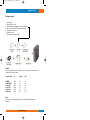
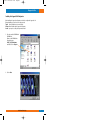
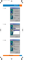
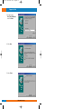
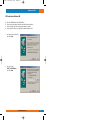
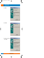
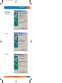
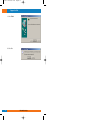
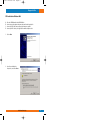
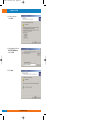
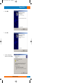
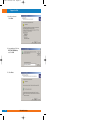
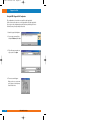
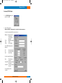
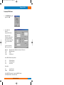
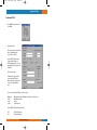
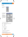
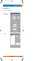
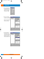
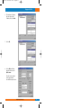
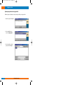
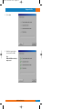
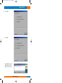
CJT 81x
02-10-2001 11:45
Pagina 1
Installation Manual
CopperJet 81x
ADSL Modem series
CopperJet 81x = 810, 811, 812 & 813
Allied Data
TECHNOLOGIES
CJT 81x
02-10-2001 11:45
Pagina 2
CopperJet 81x
Contents
Packaging contents.....................................................................................................................................3
Ethernet Installation Guide.........................................................................................................................4
Installing the CopperJet 81x Configurator...............................................................................................5
USB Installation for Windows 98 SE ........................................................................................................9
USB Installation for Windows ME. .........................................................................................................13
USB installation for Windows 2000.........................................................................................................17
Using the ADSL CopperJet 81x Configurator........................................................................................22
Configuring RFC1483 Bridged ..................................................................................................................23
Configuring RFC1483 Routed ....................................................................................................................25
Configuring PPPoA ....................................................................................................................................27
Configuring PPPoE.....................................................................................................................................29
Configuring PPTP .......................................................................................................................................31
Configuring IPoA ........................................................................................................................................33
Configuring the DHCP server...................................................................................................................35
Uploading the profile into the CopperJet 81x .......................................................................................38
Retrieving the profile from your CopperJet 81x ..................................................................................40
Updating the firmware in the CopperJet 81x ........................................................................................42
Troubleshooting guide...............................................................................................................................44
Glossary .......................................................................................................................................................46
We continue to improve our products, in order to supply our customers with the best possible service, therefore all technical
and physical specifications are subject to changes without any prior notification..
2
Allied Data Technologies
CJT 81x
02-10-2001 11:45
Pagina 3
CopperJet 81x
Packaging contents
1.
2.
3.
4.
5.
6.
7.
CopperJet 81x..
Ethernet RJ45 cross cable.
USB cable (Not included with the CopperJet 812 and 813).
RJ11 modem cable with PTT plug (country dependent).
CD with drivers and manual.
Installation manual.
Power adapter (country dependent).
Caution!
To prevent overheating, make sure enough free space is available on both sides, and above the
CopperJet 81x to permit free airflow.
Production Name:
Line
Ethernet
USB
CJ8M0 E/U
CJ8M0 E/U ISDN
CopperJet 810
CopperJet 811
CopperJet 812
CopperJet 813
PSTN
ISDN
PSTN
ISDN
PSTN
ISDN
Yes
Yes
Yes
Yes
Yes
Yes
Yes
Yes
Yes
Yes
No
No
Advice:
Set for the Copperjet 81x with firmware version 4.17 or higher the Line Modulation on
Multimode.
Allied Data Technologies
3
CJT 81x
02-10-2001 11:45
Pagina 4
CopperJet 81x
Ethernet Installation Guide
Note: You must have installed an Ethernet 10Base-T card in your computer first.
Installation when you already have a LAN connection.
1. Connect your CopperJet 81x with the Ethernet straight cable to your Ethernet Hub.
2. Connect your RJ11 cable to your CopperJet 81x, and into the phone outlet.
3. Connect the power adapter in a power outlet and into the CopperJet 81x
Installation when you don’t have a LAN connection.
1. Connect your PC with the Ethernet cross cable to your CopperJet 81x.
2. Connect your RJ11 cable to your CopperJet 81x, and into the phone outlet.
3. Connect the power adapter in a power outlet and into the CopperJet 81x
4
Allied Data Technologies
CJT 81x
02-10-2001 11:45
Pagina 5
CopperJet 81x
Installing the CopperJet 81x Configurator.
After installing the CopperJet configurator you be able to configure the CopperJet 81x.
During installation you can choose the setup you prefer,
Typical this will install the most common options.
Compact this will install only the CopperJet configurator.
Custom you may choose the options you want to install.
1. Place the provided CD-ROM in the
CD-ROM drive.
Browse on the CD-ROM to the
following directory.
D:\CJT_810_EU\Configurator,
and double click on Setup.exe.
2. Click on Next.
Allied Data Technologies
5
CJT 81x
02-10-2001 11:45
Pagina 6
CopperJet 81x
3. Click on Next.
4. Click on Next.
5. Click on Next.
6
Allied Data Technologies
CJT 81x
02-10-2001 11:45
Pagina 7
CopperJet 81x
6. Click on Next.
7. Click on Next.
8. Click on Next.
Allied Data Technologies
7
CJT 81x
02-10-2001 11:45
Pagina 8
CopperJet 81x
9. Click on Finish.
10. The CopperJet configurator
is now installed.
8
Allied Data Technologies
CJT 81x
02-10-2001 11:45
Pagina 9
CopperJet 81x
USB Installation for Windows 98 SE.
During the installation you need the official Windows 98 SE CD-ROM.
A:
B:
C:
D:
Place the CD-ROM provided in the CD-ROM drive.
Connect your power adapter to the power outlet and into the Copperjet 81x.
Connect your USB cable into your Copperjet 81x and your computer.
Connect your RJ11 cable to your CopperJet 81x and into the phone outlet.
1. Click on Next.
2. Click on Next.
Allied Data Technologies
9
CJT 81x
02-10-2001 11:45
Pagina 10
CopperJet 81x
3. Specify a location,
D:\CJT_810_EU\USBdrivers
and click on Next.
4. Click on Next.
5. Click on Finish.
10
Allied Data Technologies
CJT 81x
02-10-2001 11:45
Pagina 11
CopperJet 81x
6. Click on Next.
7. Click on Next.
8. Click on Next.
Allied Data Technologies
11
CJT 81x
02-10-2001 11:45
Pagina 12
CopperJet 81x
9. Click on Next.
10. Click on OK.
11. Click on Finish.
12. Click on Yes.
12
Allied Data Technologies
CJT 81x
02-10-2001 11:45
Pagina 13
CopperJet 81x
USB Installation for Windows ME.
A:
B:
C:
D:
Place the CD-ROM provided in the CD-ROM drive.
Connect your power adapter to the power outlet and into the Copperjet 81x.
Connect your USB cable into your Copperjet 81x and your computer.
Connect your RJ11 cable to your CopperJet 81x and into the phone outlet.
1. Specify the location of the driver,
and click on Next.
2. Specify a location,
D:\CJT_810_EU\USBdrivers,
and click on Next.
Allied Data Technologies
13
CJT 81x
02-10-2001 11:45
Pagina 14
CopperJet 81x
3. Click on Next.
4. Click on Finish.
5. Specify the location of the driver,
and click on Next.
14
Allied Data Technologies
CJT 81x
02-10-2001 11:45
Pagina 15
CopperJet 81x
6. Specify a location,
D:\CJT_810_EU\USBdrivers,
and click on Next.
7. Click on Next.
8. Click on Next.
Allied Data Technologies
15
CJT 81x
02-10-2001 11:45
Pagina 16
CopperJet 81x
9. Click on Finish.
10. Click on Yes.
16
Allied Data Technologies
CJT 81x
02-10-2001 11:45
Pagina 17
CopperJet 81x
USB installation for Windows 2000.
A:
B:
C:
D:
Place the CD-ROM provided in the CD-ROM drive.
Connect your power adapter to the power outlet and into the Copperjet 81x.
Connect your USB cable into your Copperjet 81x and your computer.
Connect your RJ11 cable to your CopperJet 81x and into the phone outlet.
1. Click on Next.
2. Search for a suitable driver
for my device, and click on Next.
Allied Data Technologies
17
CJT 81x
02-10-2001 11:45
Pagina 18
CopperJet 81x
3. Specify a location and
click on Next.
4. Copy manufacturer’s files from,
D:\CJT_810_EU\USBdrivers,
and click on OK.
5. Click on Next.
18
Allied Data Technologies
CJT 81x
02-10-2001 11:45
Pagina 19
CopperJet 81x
6. Click on Finish.
7. Click on Next.
8.
Search for a suitable driver
for my device, and click on Next.
Allied Data Technologies
19
CJT 81x
02-10-2001 11:45
Pagina 20
CopperJet 81x
9. Specify a location and
click on Next.
10. Copy manufacturer’s files from,
D:\CJT_810_EU\USBdrivers,
and click on OK.
11. Click on Next.
20
Allied Data Technologies
CJT 81x
02-10-2001 11:45
Pagina 21
CopperJet 81x
12. Click on Yes.
13. Click on Finish.
Allied Data Technologies
21
CJT 81x
02-10-2001 11:45
Pagina 22
CopperJet 81x
Using the ADSL CopperJet 81x Configurator.
This configuration tool is needed to create profiles for the Copperjet 81x.
Profiles can be stored for later use or can be uploaded directly to the Copperjet 81x.
You can also use the configurator when a profile has been provided by your Service
Provider.(You can go directly to the Upload section).
1. Start the CopperJet Configurator.
2. You can create a new profile by
clicking the Edit/new profile button.
3. Fill in a file name you want to use,
e.g User, and click on Open.
4. The next screen will appear.
When you choose to create a new
profile, please select the primary
function of the device.
22
Allied Data Technologies
CJT 81x
02-10-2001 11:45
Pagina 23
CopperJet 81x
Configuring RFC1483 Bridged.
1. Select RFC1483 Bridged as profile
type and click on OK.
2. Set the TCP/IP parameters.
Optional: an IP Address and Subnetmask is only needed for further management use.
Select the Line modulation. (ADSL connection Protocol)
-Multimode
-T1.413
-G.Lite
-G.Dmt
: Modem will detect
the Modulation
offered by the CO
(Preferred)
: ANSI ADSL Standard
: G.992.2
: G.992.1 Annex A
Set the ATM PVC (Virtual Circuit)
parameters.
-VPI
-VCI
-PCR
: VPI Channel Number
: VCI Channel Number
: Peak Cell Rate
Select the forwarded Packet types.
-None
: This will forward
all packets
-Forward PPP: This will only forward
PPP packets
-Forward IP : This will only forward
IP packets
Select spanning tree if this
is required.
Allied Data Technologies
23
CJT 81x
02-10-2001 11:45
Pagina 24
CopperJet 81x
Set Filter Table age, this is the time in seconds the device needs to store the
MAC-addresses.
Encapsulation.
-LLC
-VcMux
: Logical Link Control
: Null Encapsulation
DNS Relay.
Fill in the DNS server IP-Address, in your local network the DNS IP-Address will be the
CopperJet 81x IP address.(Not needed by Bridged)
Click on OK when finished, the profile will be stored in My Documents.
The profile can be uploaded to the Copperjet 81x as described in the upload section.
24
Allied Data Technologies
CJT 81x
02-10-2001 11:45
Pagina 25
CopperJet 81x
Configuring RFC1483 Routed.
1. Select RFC1483 Routed as profile
type and click on OK.
2. Set the LAN TCP/IP
parameters.
(CopperJet 81x IP-Address)
Set the interface type.
USB when the CopperJet 81x is
connected with a USB cable.
Ethernet when the CopperJet 81x
is connected with a Ethernet
cable.
Select the Line modulation.
(ADSL connection Protocol)
-Multimode
-T1.413
-G.Lite
-G.Dmt
: Modem will detect the Modulation offered by the CO (Preferred)
: ANSI ADSL Standard
: G.992.2
: G.992.1 Annex A
Set the ATM PVC (Virtual Circuit) parameters.
-VPI
-VCI
-PCR
: VPI Channel Number
: VCI Channel Number
: Peak Cell Rate
Encapsulation.
-LLC
-VcMux
: Logical Link Control
: Null Encapsulation
Set the WAN TCP/IP parameters. ( CopperJet 81x WAN IP-Address)
Set NAT (Network Address Translation) if needed.
Allied Data Technologies
25
CJT 81x
02-10-2001 11:45
Pagina 26
CopperJet 81x
You must set NAT when de LAN IP-Address differs from the WAN IP-Address.
Set Routing default gateway if needed.(CopperJet 81x WAN IP-Address)
DNS Relay.
Fill in the DNS server IP-Address, in your local network the DNS IP Address will be the
CopperJet 81x IP address.
Set the DHCP server when needed.
The CopperJet 81x can act as a DHCP server.
Go to the DHCP server section how to configure the DHCP server.
Click on OK when finished, the profile will be stored in My Documents.
The profile can be uploaded to the Copperjet 81x as described in the upload section.
26
Allied Data Technologies
CJT 81x
02-10-2001 11:45
Pagina 27
CopperJet 81x
Configuring PPPoA.
1. Select PPPoA as profile type and
click on OK.
2. Set Authentication.
Fill in your Username and Password.
Choose the Authentication
Protocol.(PAP or CHAP)
Set the LAN TCP/IP parameters.
(CopperJet 81x IP-Address)
The Default Gateway of your local
network will be the CopperJet 81x
IP-Address
Set the interface type.
USB when the CopperJet 81x is
connected with a USB cable.
Ethernet when the CopperJet 81x
is connected with a Ethernet
cable.
Select the Line modulation.(ADSL connection Protocol)
-Multimode
-T1.413
-G.Lite
-G.Dmt
: Modem will detect the Modulation offered by the CO (Preferred)
: ANSI ADSL Standard
: G.992.2
: G.992.1 Annex A
Set the ATM PVC (Virtual Circuit) parameters.
-VPI
-VCI
:VPI Channel Number
:VCI Channel Number
Allied Data Technologies
27
CJT 81x
02-10-2001 11:45
Pagina 28
CopperJet 81x
Set NAT (Network Address Translation) if needed.
You must set NAT when de LAN IP-Address differs from the WAN IP-Address.
DNS Relay.
Fill in the DNS server IP-Address, in your local network the DNS IP-Address will be the
CopperJet 81x IP address.
Set the DHCP server when needed.
The CopperJet 81x can act as a DHCP server.
Go to the DHCP server section how to configure the DHCP server.
Click on OK when finished, the profile will be stored in My Documents.
The profile can be uploaded to the Copperjet 81x as described in the upload section.
28
Allied Data Technologies
CJT 81x
02-10-2001 11:45
Pagina 29
CopperJet 81x
Configuring PPPoE.
1. Select PPPoE as profile type and
click on OK.
2. Set Authentication.
Fill in your Username and Password.
Choose the Authentication
Protocol.(PAP or CHAP)
Set the LAN TCP/IP parameters.
(CopperJet 81x IP-Address).
The Default Gateway of your local
network will be the CopperJet 81x
IP-Address
Set the interface type.
USB when the CopperJet 81x is
connected with a USB cable.
Ethernet when the CopperJet 81x
is connected with a Ethernet
cable.
Select the Line modulation.(ADSL connection Protocol)
-Multimode
-T1.413
-G.Lite
-G.Dmt
: Modem will detect the Modulation offered by the CO (Preferred)
: ANSI ADSL Standard
: G.992.2
: G.992.1 Annex A
Set the ATM PVC (Virtual Circuit) parameters.
-VPI
-VCI
: VPI Channel Number
: VCI Channel Number
Allied Data Technologies
29
CJT 81x
02-10-2001 11:45
Pagina 30
CopperJet 81x
Set NAT (Network Address Translation) if needed.
You must set NAT when de LAN IP-Address differs from the WAN IP-Address.
DNS Relay.
Fill in the DNS server IP-Address, in your local network the DNS IP-Address will be the
CopperJet 81x IP address.
Set the DHCP server when needed.
The CopperJet 81x can act as a DHCP server.
Go to the DHCP server section how to configure the DHCP server.
Click on OK when finished, the profile will be stored in My Documents.
The profile can be uploaded to the Copperjet 81x as described in the upload section.
30
Allied Data Technologies
CJT 81x
02-10-2001 11:45
Pagina 31
CopperJet 81x
Configuring PPTP.
1. Select PPTP as profile type and
click on OK.
2. Set the LAN TCP/IP parameters.
(CopperJet 81x IP-Address).
The Default Gateway of your local
network will be the CopperJet 81x
IP-Address
Set the interface type.
USB when the CopperJet 81x is
connected with a USB cable.
Ethernet when the CopperJet 81x
is connected with a Ethernet
cable.
Select the Line modulation.(ADSL connection Protocol)
-Multimode
-T1.413
-G.Lite
-G.Dmt
: Modem will detect the Modulation offered by the CO (Preferred)
: ANSI ADSL Standard
: G.992.2
: G.992.1 Annex A
Set the ATM PVC (Virtual Circuit) parameters.
-VPI
-VCI
:VPI Channel Number
:VCI Channel Number
DNS Relay.
Fill in the DNS server IP-Address, in your local network the DNS IP-Address will be the
CopperJet 81x IP address.
Allied Data Technologies
31
CJT 81x
02-10-2001 11:45
Pagina 32
CopperJet 81x
Click on OK when finished, the profile will be stored in My Documents.
The profile can be uploaded to the Copperjet 81x as described in the upload section.
32
Allied Data Technologies
CJT 81x
02-10-2001 11:45
Pagina 33
CopperJet 81x
Configuring IPoA.
1. Select IPoA as profile type and
click on OK.
2. Set the LAN TCP/IP parameters.
(CopperJet 81x IP-Address)
Set the interface type.
USB when the CopperJet 81x is
connected with a USB cable.
Ethernet when the CopperJet 81x
is connected with a Ethernet
cable.
Select the Line modulation. (ADSL connection Protocol)
-Multimode
-T1.413
-G.Lite
-G.Dmt
: Modem will detect the Modulation offered by the CO (Preferred)
: ANSI ADSL Standard
: G.992.2
: G.992.1 Annex A
Set the ATM PVC (Virtual Circuit) parameters.
-VPI
-VCI
-PCR
: VPI Channel Number
: VCI Channel Number
: Peak Cell Rate
Set the WAN TCP/IP parameters. ( CopperJet 81x WAN IP-Address)
Set NAT (Network Address Translation) if needed.
You must set NAT when de LAN IP-Address differs from the WAN IP-Address.
Allied Data Technologies
33
CJT 81x
02-10-2001 11:45
Pagina 34
CopperJet 81x
Set Routing default gateway if needed.(CopperJet 81x WAN IP-Address)
DNS Relay.
Fill in the DNS server IP-Address, in your local network the DNS IP Address will be the
CopperJet 81x IP address.
Set the DHCP server when needed.
The CopperJet 81x can act as a DHCP server.
Go to the DHCP server section how to configure the DHCP server.
Click on OK when finished, the profile will be stored in My Documents.
The profile can be uploaded to the Copperjet 81x as described in the upload section.
34
Allied Data Technologies
CJT 81x
02-10-2001 11:45
Pagina 35
CopperJet 81x
Configuring the DHCP Server.
This is a example how to configure the DHCP Server.
1. Select DHCP Server,
and click on Configuration.
2. Click on Add.
Allied Data Technologies
35
CJT 81x
02-10-2001 11:45
Pagina 36
CopperJet 81x
3. Fill in your Subnet and Netmask.
The Subnet must be in the same
network as your CopperJet 81x
IP Address, and click on OK.
4. Fill in the range of IP Addresses
you want to use, and click on Add.
Note: Do not use the CopperJet 81x
IP Address in your IP range.
5. Fill in the Default or Max. lease
time, this is the time in seconds
you have the assigned IP Address,
after this time you get a another
IP Address from the DHCP Server.
36
Allied Data Technologies
CJT 81x
02-10-2001 11:45
Pagina 37
CopperJet 81x
6. Fill in the Routers IP Address,
this is the CopperJet 81x
IP Address, and click on Add.
7. Click on OK.
8. Click on OK when finished,
the profile will be stored in
My Documents.
The profile can be uploaded
to the CopperJet 81x as
described in the upload section.
Allied Data Technologies
37
CJT 81x
02-10-2001 11:45
Pagina 38
CopperJet 81x
Uploading the profile into the CopperJet 81x.
With the CopperJet configurator you can upload your profile into your CopperJet 81x.
1. Start the CopperJet Configurator.
2. Click on the MAC address,
and click on Upload profile.
3. Select the profile you want to
upload, and click on Open.
38
Allied Data Technologies
CJT 81x
02-10-2001 11:45
Pagina 39
CopperJet 81x
4. Click on Start.
5. Wait till the CopperJet 81x has
rebooted, and click on Exit.
Note:
Additional LAN Network settings
maybe needed.
Allied Data Technologies
39
CJT 81x
02-10-2001 11:45
Pagina 40
CopperJet 81x
Retrieving the profile from your CopperJet 81x.
With the CopperJet configurator you will be able to retrieve your profile from your
CopperJet 81x.
1. Start the CopperJet Configurator.
2. Click on the MAC address,
and click on Get profile.
3. Give the profile a file name
e.g Save, and click on Save.
4. Click on Ok.
40
Allied Data Technologies
CJT 81x
02-10-2001 11:45
Pagina 41
CopperJet 81x
5. Your saved profile is now stored in
My Documents.
Allied Data Technologies
41
CJT 81x
02-10-2001 11:45
Pagina 42
CopperJet 81x
Updating the firmware in the CopperJet 81x.
With the CopperJet configurator you can upload a new firmware into your CopperJet 81x.
New firmware will be available on our website.
Note: Don’t disconnect the power suply, USB cable or Ethernet cable during the upload.
1. Start the CopperJet Configurator.
2. Click on the MAC address,
and click on Update firmware.
3. Select the binary to upload,
and click on Open.
42
Allied Data Technologies
CJT 81x
02-10-2001 11:45
Pagina 43
CopperJet 81x
4. Click on Start.
5. Click on Exit.
6. Click on Refresh, the CopperJet
81x MAC address and new
firware version will be shown.
Allied Data Technologies
43
CJT 81x
02-10-2001 11:45
Pagina 44
CopperJet 81x
Troubleshooting guide.
This section may help when you may find some problems with the product.
Please check our website: www.allieddata.com for updates on manuals, drivers and firmware.
General
1.
Power-LED is not burning:
- Check if your power adapter is connected to your ADSL modem and the power network
2.
ADSL-LED is not burning:
Your ADSL modem doesn’t see the Central Office Equipment.
- Check if the cable to the telephone network is connected to your ADSL modem and
the telephone wall outlet.
- Check if your ADSL provider has configured ADSL on your telephone line
- Check the wiring-scheme your provider is using.
The Copperjet uses the inner-wires (pin 3&4) for the connection.
Some providers do use the outer-wires (pin 2&5) for the connection.
- Check if you configured the right connection protocol in your ADSL modem
(G.lite, G.dmt, Multi mode or T1.413 issue 2)
3.
ADSL-LED is flashing:
Your ADSL modem has located a Central Office Equipment and is trying to get
synchronized. (This should not take more than 7-9 seconds)
- Check if you configured the right connection protocol in your ADSL modem
(G.lite, G.dmt or T1.413 issue 2)
4.
To set your ADSL modem to factory settings
- Press the softkey for 15 seconds untill all LED’s will stop flashing and the modem will
reboot with the default settings.
Ethernet configuration
5.
44
Ethernet-LED is not burning:
Your ADSL modem hasn’t detected an active Ethernet link to a hub/switch or computer
- Check if you use straight Ethernet cable to connect to a hub or Ethernet switch
- Check if you use an Ethernet cross-cable to connect directly to an Ethernet port
on your PC
- Check if you use a 10BaseT connection to connect your ADSL modem to the
Ethernet network
- Check if the USB LED is off. If the USB LED is burning, you have connected your ADSL
modem to a PC. This disables the Ethernet port of the ADSL modem.
Allied Data Technologies
CJT 81x
02-10-2001 11:45
Pagina 45
CopperJet 81x
6.
ADSL Profile Configurator or Loader doesn’t detect an ADSL modem in your network
- Check if the modem is in the same physical LAN as the configuring PC
- Check if the modem’s IP address is in the same IP-subnet as the configuring PC.
This IP-address can be found in the downloaded profile using the ADSL Profile
Configurator. If the configured IP-address is not in the same subnet, then use the ADSL
Profile Configurator or Loader from a PC which IP address is configured within the same
subnet as your ADSL modem, or reset the modem to it’s factory default settings (see 4.).
Review the profile (especially the IP-addresses) you’re using before trying to download it
again.
USB
7.
USB-led is not burning: Your ADSL modem doesn’t detect a USB host
- Does your PC have USB support installed properly?
8.
After installing a PPP ATM dialup-adapter, the system doesn’t add this entry to it’s list of
devices
- This is a known issue when the ADSL modem does not have an active ADSL link to your
provider.
Please check and make sure that the ADSL led is burning before installing the ADSL
modem.
Do not reinstall the drivers but make sure that you have an active ADSL link and reboot
your PC.
9.
Can not bind a TCP/IP protocol stack to ATM SVC using an IPoA configuration.
- This is a known issue when the ADSL modem does not have an active ADSL link to your
provider. (See point 8.)
Allied Data Technologies
45
CJT 81x
02-10-2001 11:45
Pagina 46
CopperJet 81x
Glossary
ADSL
Strictly speaking, Asymmetric Digital Subscriber Line defines only a way of transmitting
broadband data (at speeds between 64kbps and 8Mbps) between a user’s premises
(home or office) and the local telephone exchange. In order to increase the number of
customers that it is possible to serve, the upstream speed (from the user) is lower than the
downstream speed (to the user), so the service is ‘asymmetric’. The scope of the definition is
similar to that of a modem, such as V.90; the format or meaning of the data is not defined
(except in the case of G.992.2 (G.lite) where ATM is defined as the low-level protocol).
However, ATM is de facto the standard low level protocol used with ADSL.
Since getting data to and from the local telephone exchange is not in itself of much use, and the
raison d’être of ADSL services is to enable high-speed access to the Internet, discussions of
ADSL (including this one) generally include how the data connection is extended to an Internet
Service Provider, and so, to the Internet. So, we assume that ADSL is used to carry TCP/IP data
but how this is done is not part of the ADSL specification.
ATM
This protocol is always used as the low level protocol (above the ADSL transmission layer).
This is because it is a flexible and convenient way for the telco to extend the user’s data
connection from the local exchange (where the ADSL connection ends) to the ISP.
Telcos have substantial experience of using ATM to carry broadband data within their networks.
Strictly speaking, ‘Full rate’ ADSL (G.dmt, G.992.1) does not specify that ATM is the low level
protocol, so another protocol could, in theory, be used, but ATM is the de facto standard.
G.lite (G.992.2) does, however, specify ATM as the low level protocol.
ATM connections are usually PVCs (permanent virtual circuits); the route is pre-configured
through the network. SVCs (switched virtual circuits) exist but are not widely used.
The owner of the data on an ATM link is described by two parameters: the VPI
(Virtual Path Identifier) and VCI (Virtual Channel Identifier). Each ATM switch defines in its
configuration the mapping between a VPI/VCI combination on one port and a different VPI/VCI
combination on another port. This configuration defines the route through the ATM switch.
Note that this means that a particular data connection may be given many different VPI/VCI
‘addresses’ as it passes through the network.
Authentication
Many ADSL connections employ PPP encapsulation in order that authentication can be
performed in the same way for ADSL users as it is for analogue modem and ISDN users.
Since the connection from the user to the ISP is, in effect, a point-to-point ATM connection
using a PVC with a fixed route defined by the telco, one could debate the need for
authentication. The ISP could, in theory, work out who you are from the ATM VPI/VCI that your
connection appears on. However, ISPs are not geared up to manage ATM VPI/VCIs but they are
geared up to handle PPP authentication, so this is currently the norm.
46
Allied Data Technologies
CJT 81x
02-10-2001 11:45
Pagina 47
CopperJet 81x
Authentication will normally be performed by the BAS, probably by reference to a RADIUS
server.
BAS
The Broadband Access Server could be described as a highly flexible and configurable
ATM/PPP/IP switch/router. The function of the BAS is to ‘unwrap’ any encapsulation used to
carry the TCP/IP traffic over the ATM connection and pass the data into the ISPs normal
network. In addition, if PPP is one of the encapsulating protocols, the BAS performs the user
authentication (perhaps using an authentication server such as RADIUS to verify the
username/password combination).
Splitting this functionality from the DSLAM increases the implementation flexibility by allowing
the connection to the ISP’s IP network (and the PPP authentication, if necessary) to take place
at the ISP’s premises, across an ATM network from the DSLAM.
In some configurations, the BAS will allow switching between ISPs based on the
userid/password that the user supplies in the PPP authentication.
This architecture allows the ISP to replace the Access Server that terminates and authenticates
the PPP connection from customers with analogue modems and ISDN lines with the BAS for
ADSL customers. If PPP is used on the ADSL connection, then the ADSL user connected
through the BAS appears in the ISP’s network in exactly the same way as an analogue modem
or ISDN user; the same authentication server could be handling both conventional and ADSL
users. This explains the popularity of PPP as an encapsulating protocol.
The ‘Redback SMS100’ is an example of a popular BAS.
Bridged/Routed connections
Bridge-based solutions are perceived by some telcos and ISPs as the simpler, cheaper, entry
level ADSL offering. These telcos/ISPs tend to regard routed connections as ‘complicated,
expensive and advanced’. It is difficult to see how this can be justified, since the thinnest of
passive devices can use a routed connection using Microsoft’s PPP over ATM stack in
Windows 98SE, Me and 2000.
Note that some telcos launching services more recently (for instance BT) have chosen to
provide only routed solutions even for their low-end services, skipping the bridge.
Bridged solutions are normally either:
* Ethernet with LLC/SNAP (this is one of the options of RFC 1483)
Or
* PPP over Ethernet (PPPoE - there is no ‘real’ RFC for this, only an ‘informational’)
Routed solutions are normally either
* PPP over ATM (PPPoATM - RFC 2364)
Or
* IP with LLC/SNAP (this is another option of RFC 1483)
Allied Data Technologies
47
CJT 81x
02-10-2001 11:45
Pagina 48
CopperJet 81x
Note that ‘RFC 1483’ by itself doesn’t tell you what the protocol is - you need to know if the
connection is bridged or routed to know what ‘RFC 1483’ means.
DSLAM
The unit in the telco’s local exchange that houses the ADSL modems and consolidates all the
data connections onto a single ATM fibre connection, typically at 155Mbps currently.
The key configuration parameters of the DSLAM are for each line (user):
* ADSL standards supported (for instance, is G.lite supported?)
* Minimum and maximum allowed downstream speeds (minimum is normally 32kbps)
* Minimum and maximum allowed upstream speeds (minimum is normally 32kbps)
* User-side ATM VPI/VCI - can be the same for all users for support simplicity
* The ATM VPI/VCI that the user’s ATM connection is mapped to on the fibre connection.
This must be different for each user; it determines the BAS that the user is connected to.
If there is a choice of ISPs, then this VPI/VCI (and the routing in any further ATM switches) may
determine which ISP the user is connected to.
In some configurations, the BAS will allow switching between ISPs based on the
userid/password that the user supplies.
A typical DSLAM might serve several hundred users, so it is clear that all these users cannot
expect 8Mbps bandwidth at the same time if the upstream ATM fibre link is running at 155Mbps.
Encapsulation
The process of placing data inside a wrapper (or envelope) in order to make it compatible with
a protocol. The term is typically used where one protocol is placed inside another in a nonstandard way (often where a low-level protocol is placed within a high-level protocol or one
network protocol is placed inside another).
Analogy: A letter has to be placed inside a correctly addressed and stamped envelope for it to
be compatible with the postal service. A postcard is already compatible with the postal service
(as long as it is correctly stamped and addressed) so does not need encapsulation but the
postcard has severe limitations, not least, the short message length. A letter does not have an
inherent address like a postcard but, inside an envelope, the letter gives much greater flexibility
to the user (you can write much more using several pieces of paper and include a photograph
or even include a lock of hair). The postal service sees only the envelope and doesn’t care
what’s inside it. There’s nothing to stop you putting a postcard inside an envelope, so is this
encapsulation?
You may need to encapsulate data in a protocol just to get it across a network, or it may be
necessary to put an ‘extra’ envelope around the data before it is passed to the network so that
the recipient will know what to do with the data when it arrives.
Analogy: Inter-office mail may be consolidated into a single envelope to save postage charges.
But if individual documents are placed directly into one big envelope then the receiving post
room will not be able to deliver them to the correct place.
48
Allied Data Technologies
CJT 81x
02-10-2001 11:45
Pagina 49
CopperJet 81x
So, you place each document into its own ‘internal’ envelope before placing all the ‘internal’
envelopes inside the big one.
Another, more appropriate analogy: An ISP may specify that all TCP/IP messages must be
placed inside a brown envelope marked ‘PPP’ with your name and encrypted password written
on it before being placed inside the ‘real’ ATM envelope and sent to the ISP. The reason: ‘we
like to be sure who all messages come from and we’ve always done it this way’.
This is how PPP encapsulation is used in ADSL.
Ethernet over LLC/SNAP
This is a bridged connection method and is one of the options of RFC 1483.
Note that ‘RFC 1483’ by itself doesn’t tell you what the protocol is - you need to know if the
connection is bridged or routed to know what ‘RFC 1483’ means.
Filter
In this context, a device that separates the low frequency (voice) from the high frequencies
(data). Without a filter, picking up a phone that is connected to an ADSL line can cause
sufficient disturbance to the line to cause a retrain to occur; this may stop data transmission for
up to 15 seconds.
G.hs = G.994.1
G.994.1 defines the “handshaking” protocol that defines how the ADSL modems each whistle to
allow their detection by the other and agree how the ADSL line is going to work.
This is just like two V.34/V.90 modems whistling, burbling and bonging to each other to decide
how slow a connection to give you.
The synchronisation and training phase terminates in ‘showtime’. The G.994.1 recommendation
defines the use of multiple tones in parallel to give resilience to interference; earlier
handshaking techniques used a single tone and were susceptible to external interference
‘knocking out’ this tone and preventing handshaking from proceeding.
G.Lite = G.992.2, derived from T1.413 Issue 2
In 1999, it seemed that this was going to be very important, but now ‘Full rate’ has fought back.
In any case, the distinction is largely academic because all current and planned ADSL chipsets
and DSLAMs that do G.992.2 also do G.992.1 (Full rate).
G.992.2 specifies ATM as the low level protocol, maximum up/down speeds of 512kbps/1.5Mbps,
the fast retrain option and power saving.
Fast retrain is intended to reduce the impact of picking up a phone on the ADSL enabled line.
Without a filter to prevent the phone interfering with the data, taking a phone off-hook leads to a
retrain sequence that could last 15 seconds.
Fast retrain uses stored information in the user’s modem as a start-point for the training process
rather than starting again from the beginning. If the stored configuration still works, the fast
retrain can be completed in less than a second.
Allied Data Technologies
49
CJT 81x
02-10-2001 11:45
Pagina 50
CopperJet 81x
G.dmt = G.992.1, derived from T1.413; also known as ‘Full rate’
This is the type of ADSL most commonly implemented now.
IP over LLC/SNAP
This is a routed connection method and is one of the options of RFC 1483.
Note that ‘RFC 1483’ by itself doesn’t tell you what the protocol is - you need to know if the
connection is bridged or routed to know what ‘RFC 1483’ means.
Micro-filter
A filter designed to be connected between the ADSL line and every phone that is connected to
the line.
PPP
The protocol used to carry TCP/IP traffic to the ISP across modem and ISDN links.
PPP incorporates authentication (username/password checking).
Because of its historical use for modem and ISDN users, ISPs favour the use of PPP as an
encapsulating protocol for ADSL users.
PPP over ATM - RFC 2364
PPP over ATM (PPPoATM) is the most elegant and simple implementation that provides PPP
encapsulation over a routed ADSL connection.
Microsoft provides a PPP over ATM stack in Windows 98SE, Windows Me and Windows 2000
and this provides an almost ideal implementation for ‘passive’ ADSL modems such as internal
cards and USB devices.
PPP over Ethernet
PPP over Ethernet (PPPoE) is used in some existing ADSL services. It is a less than elegant
solution since it requires a custom ‘driver’ in the user’s PC. This driver works in a similar manner
to Dial-Up Networking, but Microsoft have not implemented it so 3rd-party software is required.
So, even if you’re using an intelligent (as opposed to ‘passive’) device, you’re dependent on the
PPP over Ethernet (PPPoE) client being available for your operating system platform.
RFC 1483
This RFC includes 4 options, only two of which are relevant to ADSL:
* IP over LLC/SNAP is a routed connection method, sometimes referred to as “RFC1483R”
* Ethernet over LLC/SNAP is a bridged connection method, sometimes referred to as
“RFC1483B”
Note that ‘RFC 1483’ by itself doesn’t tell you what the protocol is - you need to know if the
connection is bridged or routed to know what ‘RFC 1483’ means.
RFC 2516
‘Informational’ RFC describing PPP over Ethernet.
50
Allied Data Technologies
CJT 81x
02-10-2001 11:45
Pagina 51
CopperJet 81x
Showtime
Jargon for the ADSL state (that may be signalled by a green ‘line’ LED being permanently on
rather than flashing) equivalent to the ‘CD’ LED or ‘CONNECT’ message from a modem.
May mean (if you’re unlucky and the line is bad) that you have a 32kbps connection to the
DSLAM in your local exchange, since this is normally the ‘minimum’ speed defined as
‘acceptable’. Note that this does not mean you can get past the DSLAM and transmit any data;
for a useful connection you need to be using the correct ATM VPI/VCI and the correct
encapsulation across the ADSL link. Of course, this is not part of the ADSL specification.
Advice: Set for the CopperJet 81x with firmware version 4.17 or higher the
Line Modulation on Multimode
Splitter
Filter with a low pass (telephone) socket and a high pass socket which is used to connect to the
ADSL modem. At the local exchange another splitter is connected to the telephone network
(low pass) and the DSLAM (high pass)
Synchronisation and Training
This is the modem initialisation process defined by the G.994.1 (G.hs handshaking)
recommendation. This process, if successful, ends in the state known as ‘showtime’.
VPI/VCI
The ATM Virtual Path Identifier (VPI) and Virtual Channel Identifier (VCI) uniquely identify a data
path on an ATM link. An ATM switch (or other device incorporating ATM switching capability
like a DSLAM or BAS) can be configured to take data from one VPI/VCI on an incoming link and
map it to another VPI/VCI on an outgoing link.
This configuration defines the route through the ATM switch. Note that this means that a
particular data connection may be given many different VPI/VCI ‘addresses’ as it passes
through the network.
Allied Data Technologies
51
CJT 81x
02-10-2001 11:45
Pagina 52
CopperJet 81x
Declaration of Conformity
Manufacturer’s Name:
ALLIED DATA TECHNOLOGIES B.V.
Manufacturer’s Address:
P.O. box 788
3200 AS Spijkenisse
The Netherlands
declares that the product:
Product Name:
CopperJet 810
Conforms to the following standard(s) or other normative document(s):
EMC:
EN 55022 Class A (1994) Limits and methods of measurement of radio
disturbance characteristics of information technology equipment.
EN 50082-1 (1992) Electromagnetic compatibility - Generic immunity
standards for residential, commercial and light industry.
EN 300386-2 (2000) Electromagnetic compatibility - Generic immunity
standards for commercial and light industry.
FCC Part 15, Class A, Subpart B
Safety:
EN 60950 (1992/93) Safety of information technology equipment,
including electrical business equipment.
UL (IEC950) Statement that the equipment has been designed and built
according to IEC950 and/or the compatible edition of EN60950.
Telecom:
ANSI T1.413 (1998) FCC Part 68, Sub D
CE:
Statement of Conformance to electrical safety & EMI requirements
Supplementary Information:
The product herewith complies with the requirements of the EMC Directive 89/336/EEC and the
Low Voltage Directive 73/23/EEC. The product was tested in a typical configuration.
Spijkenisse, 21 September 2001
Quality Management
European Contact: ALLIED DATA TECHNOLOGIES B.V.
52
Allied Data Technologies
CJT 81x
02-10-2001 11:45
Pagina 53
CopperJet 81x
INFORMATION TO USER
This device complies with Part 15 of the FCC Rules. Operation is subject to the following two conditions: (1) This device may
not cause harmful interference, and (2) This device must accept any interference received, including interference that may
cause undesired operation.
This equipment has been tested and found to comply with the limits for Class B Digital Device, pursuant to Part 15 of the FCC
Rules. These limits are designed to provide reasonable protection against harmful interference in a residential installation.
This equipment generates and can radiate radio frequency energy and, if not installed and used in accordance with the
instructions, may cause harmful interference to radio communications. However, there is no guarantee that interference will
not occur in a particular installation. If this equipment does cause harmful interference to radio or television reception, which
can be determined by turning the equipment off and on, the user is encouraged to try to correct the interference by one or
more of the following measures.
Reorient or relocate the receiving antenna
Increase the separation between the equipment and receiver
Connect the equipment into an outlet on a circuit different from that to which the receiver is connected
Consult the dealer or an experienced radio/TV technician for help
Any changes or modifications not expressly approved by Allied Data Technologies could void the userís authority to operate
the equipment.
ANALOGUE DEVICE WARNINGS
This equipment complies with Part 68 of the Federal Communications Commission (FCC) rules for the United States.
A label is located on the underside of the base unit containing both the FCC registration number and Ringer Equivalence
Number (REN). You must upon request, provide the following information to your local telephone company:
Service Order Code:
USOC Jack Type:
REN:
N/A
CA11A
0.1B
Should you experience trouble with this telephone equipment, please contact:
Allied Data Technologies
4557 Crystal Clear Drive
Hilliard, 43026 Ohio
The REN is used to determine the quantity of devices that may be connected to the telephone line. Excessive RENs on the
telephone line may result in the devices not ringing in response to an incoming call. In most, but not all areas, the sum of
RENs should not exceed five (5.0). To be certain of the number of devices that may be connected to a line, as determined by
the total RENs, contact the local telephone company.
If trouble is experienced with this equipment CopperJet 810, for repair or warranty information, please contact Allied Data
Technologies +1 (614) 7774232. If the equipment is causing harm to the telephone network, the telephone company may
request that you disconnect the equipment until the problem is resolved.
This equipment cannot be used on public coin phone service provided by the telephone company.
Connection to party line service is subject to state tariffs.
Your telephone company may discontinue your service if your equipment causes harm to the telephone network.
They will notify you in advance of disconnection, if possible. During notification, you will be informed of your right to file a
complaint to the FCC.
Occasionally, your telephone company may make changes in its facilities, equipment, operation, or procedures that could
affect the operation of your equipment. If so, you will be given advance notice of the change to give you an opportunity to
maintain uninterrupted service.
Allied Data Technologies
53
CJT 81x
02-10-2001 11:45
Pagina 54
CopperJet 81x
Declaration of Conformity
Manufacturer’s Name:
ALLIED DATA TECHNOLOGIES B.V.
Manufacturer’s Address:
P.O. box 788
3200 AS Spijkenisse
The Netherlands
declares that the product:
Product Name:
CopperJet 811
Conforms to the following standard(s) or other normative document(s):
Safety:
EN 60950 (1992/93) Safety of information technology equipment,
including electrical business equipment.
UL (IEC950) Statement that the equipment has been designed and built
according to IEC950 and/or the compatible edition of EN60950.
CE:
Statement of Conformance to electrical safety & EMI requirements
Supplementary Information:
The product was tested in a typical configuration.
Spijkenisse, 21 September 2001
Quality Management
European Contact: ALLIED DATA TECHNOLOGIES B.V.
54
Allied Data Technologies
CJT 81x
02-10-2001 11:45
Pagina 55
CopperJet 81x
Declaration of Conformity
Manufacturer’s Name:
ALLIED DATA TECHNOLOGIES B.V.
Manufacturer’s Address:
P.O. box 788
3200 AS Spijkenisse
The Netherlands
declares that the product:
Product Name:
CopperJet 812
Conforms to the following standard(s) or other normative document(s):
EMC:
EN 55022 Class A (1994) Limits and methods of measurement of radio
disturbance characteristics of information technology equipment.
EN 50024, (1998) Electromagnetic compatibility - Generic immunity standards
for residential, commercial and light industry.
EN 300386-2, (2000) Electromagnetic compatibility - Generic immunity
standards for commercial and light industry.
FCC Part 15, Class A, Subpart B
Safety:
EN 60950 (1992/93) Safety of information technology equipment,
including electrical business equipment.
UL (IEC950) Statement that the equipment has been designed and built
according to IEC950 and/or the compatible edition of EN60950.
Telecom:
ANSI T1.413 (1998) FCC Part 68, Sub D
CE:
Statement of Conformance to electrical safety & EMI requirements
Supplementary Information:
The product herewith complies with the requirements of the EMC Directive 89/336/EEC and the
Low Voltage Directive 73/23/EEC. The product was tested in a typical configuration.
Spijkenisse, 21 September 2001
Quality Management
European Contact: ALLIED DATA TECHNOLOGIES B.V.
Allied Data Technologies
55
CJT 81x
02-10-2001 11:45
Pagina 56
CopperJet 81x
INFORMATION TO USER
This device complies with Part 15 of the FCC Rules. Operation is subject to the following two conditions: (1) This device may
not cause harmful interference, and (2) This device must accept any interference received, including interference that may
cause undesired operation.
This equipment has been tested and found to comply with the limits for Class B Digital Device, pursuant to Part 15 of the FCC
Rules. These limits are designed to provide reasonable protection against harmful interference in a residential installation.
This equipment generates and can radiate radio frequency energy and, if not installed and used in accordance with the
instructions, may cause harmful interference to radio communications. However, there is no guarantee that interference will
not occur in a particular installation. If this equipment does cause harmful interference to radio or television reception, which
can be determined by turning the equipment off and on, the user is encouraged to try to correct the interference by one or
more of the following measures.
Reorient or relocate the receiving antenna
Increase the separation between the equipment and receiver
Connect the equipment into an outlet on a circuit different from that to which the receiver is connected
Consult the dealer or an experienced radio/TV technician for help
Any changes or modifications not expressly approved by Allied Data Technologies could void the userís authority to operate
the equipment.
ANALOGUE DEVICE WARNINGS
This equipment complies with Part 68 of the Federal Communications Commission (FCC) rules for the United States.
A label is located on the underside of the base unit containing both the FCC registration number and Ringer Equivalence
Number (REN). You must upon request, provide the following information to your local telephone company:
Service Order Code:
USOC Jack Type:
REN:
N/A
CA11A
0.1B
Should you experience trouble with this telephone equipment, please contact:
Allied Data Technologies
4557 Crystal Clear Drive
Hilliard, 43026 Ohio
The REN is used to determine the quantity of devices that may be connected to the telephone line. Excessive RENs on the
telephone line may result in the devices not ringing in response to an incoming call. In most, but not all areas, the sum of
RENs should not exceed five (5.0). To be certain of the number of devices that may be connected to a line, as determined by
the total RENs, contact the local telephone company.
If trouble is experienced with this equipment CopperJet 812, for repair or warranty information, please contact Allied Data
Technologies +1 (614) 7774232. If the equipment is causing harm to the telephone network, the telephone company may
request that you disconnect the equipment until the problem is resolved.
This equipment cannot be used on public coin phone service provided by the telephone company.
Connection to party line service is subject to state tariffs.
Your telephone company may discontinue your service if your equipment causes harm to the telephone network.
They will notify you in advance of disconnection, if possible. During notification, you will be informed of your right to file a
complaint to the FCC.
Occasionally, your telephone company may make changes in its facilities, equipment, operation, or procedures that could
affect the operation of your equipment. If so, you will be given advance notice of the change to give you an opportunity to
maintain uninterrupted service.
56
Allied Data Technologies
CJT 81x
02-10-2001 11:45
Pagina 57
CopperJet 81x
Declaration of Conformity
Manufacturer’s Name:
ALLIED DATA TECHNOLOGIES B.V.
Manufacturer’s Address:
P.O. box 788
3200 AS Spijkenisse
The Netherlands
declares that the product:
Product Name:
CopperJet 813
Conforms to the following standard(s) or other normative document(s):
Safety:
EN 60950 (1992/93) Safety of information technology equipment,
including electrical business equipment.
CE:
Statement of Conformance to electrical safety & EMI requirements
Supplementary Information:
The product was tested in a typical configuration.
Spijkenisse,21 September 2001
Quality Management
European Contact: ALLIED DATA TECHNOLOGIES B.V.
Allied Data Technologies
57
CJT 81x
02-10-2001 11:45
Pagina 58
CopperJet 81x
Warranty
This ALLIED DATA TECHNOLOGIES B.V. product is warranted against defects in material and workmanship
for a period of five years from date of shipment. During the warranty period, ALLIED DATA TECHNOLOGIES
B.V. will, at its option, either repair or replace products that prove to be defective. For warranty service or
repair, this product must be returned to a service facility designated by ALLIED DATA TECHNOLOGIES B.V.
Buyer shall prepay shipping charges to ALLIED DATA TECHNOLOGIES B.V. and ALLIED DATA
TECHNOLOGIES B.V shall pay shipping charges to return the product to Buyer. However, Buyer shall pay all
shipping charges, duties and taxes for products returned to ALLIED DATA TECHNOLOGIES B.V. from another
country.
Limitation of Warranty
The foregoing warranty shall not apply to defects resuiting from improper or inadequate maintenance by
Buyer, Buyer-supplied firmware or interfacing, unauthorized modification or misuse, operation outside of the
environmental specifications for the product, or improper site preparation or maintenance.
Exclusive Remedies
The remedies provided herein are the Buyer's sole and exclusive remedies. ALLIED DATA TECHNOLOGIES
B.V. shall not be liabie for any direct, indirect special, incidental, or consequential damages, whether based
on contract, tort, or any legal theory.
Safety Warnings
The exclamation point within a triangie is intended to warn the operator or service personnel of operation
and maintenance factors relating to the product and its operating environment that could pose a safety
hazard. Always observe standard safety precautions during installation, operation and maintenance of this
product. Only a qualified and authorized service personnel should carry out adjustment, maintenance or
repairs to this instrument. Either the operator or the user should perform no adjustment, maintenance or
repairs.
Telecommunication Safety
The safety status of each of the ports on the Copperlet 81x is declared according to EN 41003 and is detailed
in the table below:
Safety Status Ports
SELV*
TNV** operating within limits of SELV E1
*SELV = Safety Extra-Low Voltage
** TNV =Telecommunications Network Voltage
Regulatory Information
FCC-15 User Information
This equipment has been tested and found to comply with the limits of the Class A digital device, pursuant
to Part 15 of the FCC rules. These limits are designed to provide reasonable protection against harmful
interference when the equipment is operated in a commercial environment. This equipment generates, uses
and can radiate radio frequency energy and, if not installed and used in accordance with the instruction
manual, may cause harmful interference to the radio communications. Operation of this equipment in a
residential area is likely to cause harmful interference in which case the user will be required to correct the
interference at his own expense.
Warning per EN 55022
This is Class A product. In a domestic environment, this product may cause radio interference, in which
case the user may be required to take adequate measures.
58
Allied Data Technologies
CJT 81x
02-10-2001 11:45
Notes:
Pagina 59
CJT 81x
02-10-2001 11:45
Pagina 60
Allied Data
TECHNOLOGIES
Headoffice
Allied Data Technologies bv
Netherlands
E-mail:
[email protected]
Website:
www.allieddata.com
Europe
E-mail : [email protected]
Website : www.allieddata.com
Asia
E-mail : [email protected]
Website : www.allieddata.com
USA
E-mail : [email protected]
Website : www.allieddata.com
MA-Q-CJT81x-01
60
Dealer stamp