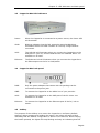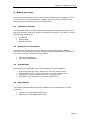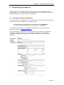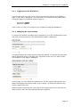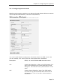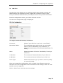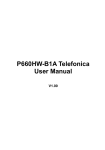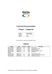
1
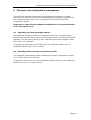
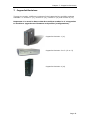
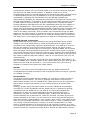
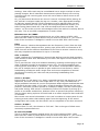
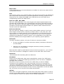
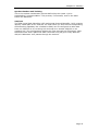
Installation Manual
CopperJet
CopperJet
CopperJet
CopperJet
CopperJet
CopperJet
810
811
820
821
822
823
Based on firmware 5.15
December 2003
Document History
Date
21 Mar 2003
21 Mar 2003
31 Mar 2003
2 Apr 2003
4 Apr 2003
7 Apr 2003
22 Apr 2003
23 Apr 2003
29 Apr 2003
17 Jul 2003
03 Nov 2003
04 Nov 2003
Version
1
1
1.1
1.2
1.3
1.4
1.5
1.6
1.7
1.8
1.9
1.10
Status
Draft
Draft
Draft
Draft
Draft
Draft
Draft
Release
Draft
Release
Release
Release
Description
Initial version
Initial version
First check
Comment + history
2nd Check and layout
Changed pictures
Updated
Updated
Headers and footers
Updated
Firmware 5.15
Updated
Product DISCLAIMER
This manual by ALLIED DATA TECHNOLOGIES B.V. (hereafter referred to as
ALLIED DATA TECHNOLOGIES) is a reflection of the current state of the products
described in it.
It has been our goal to provide a manual that is complete and clear to ensure
that our products are as easy to use. However, this manual may contain technical
inaccuracies and typing errors. As a result of rapid developments, we are also
obliged to reserve the right to implement technical modifications and
developments without prior notice. For this reason, ALLIED DATA TECHNOLOGIES
does not guarantee the contents of the manual and its permanent applicability.
Neither is ALLIED DATA TECHNOLOGIES liable for possible loss of information or
any improper use of information resulting from the consultation of this manual. In
particular, ALLIED DATA TECHNOLOGIES is not liable for any direct or indirect
damage (including loss of profits and comparable losses) resulting from the use
or improper use of this manual, even if ALLIED DATA TECHNOLOGIES or a
representative of ALLIED DATA TECHNOLOGIES has been informed that such
damage could arise. Of course, this does not detract us from our legal liability for
intentionally inflicted damage or damage on the basis of gross negligence.
In relation to the information mentioned in this manual, ALLIED DATA
TECHNOLOGIES does not guarantee that there are no industrial rights of
ownership (trademarks, patents, etc.). This also applies to commonly used brand
names, company names and product names, but these are subject to the relevant
trademark, patent and registered design laws.
The information is not to be copied, translated, reproduced or transferred or
stored on any electronic medium or other machine, neither wholly nor partly,
without prior permission in writing from ALLIED DATA TECHNOLOGIES.
The sale and use of software is subject to the ALLIED DATA TECHNOLOGIES
General Terms of Delivery and Payment as well as its License Terms.
Should any term regarding the disclaimer be or become void for legal reasons,
this will not affect the other terms.
Page 1
Contents
1
Packaging contents ...............................................................................4
2
LED Indicators and back panel ................................................................5
2.1
2.2
2.3
2.4
2.5
3
Connecting the CopperJet.......................................................................8
3.1
3.2
4
Connecting the CopperJet 81x .........................................................8
Connecting the CopperJet 82x .........................................................8
Before you start....................................................................................9
4.1
4.2
4.3
4.4
5
CopperJet 81x LED indicators ..........................................................5
CopperJet 81x back panel ...............................................................5
CopperJet 82x LED indicators ..........................................................6
CopperJet 82x back panel ...............................................................6
Softkey ........................................................................................6
IP Address Settings........................................................................9
Name Server Information ...............................................................9
ATM Settings.................................................................................9
PPP Settings .................................................................................9
Configuring the CopperJet .................................................................... 10
5.1
Accessing the build-in WebServer .................................................. 10
5.1.1
Logging in to the WebServer .................................................... 11
5.1.2
Changing the login settings ...................................................... 11
5.2
Quickstart................................................................................... 12
5.3
LAN Connections.......................................................................... 13
5.3.1
Create a new LAN connection ................................................... 13
5.3.2
Delete a LAN connection .......................................................... 13
5.3.3
Edit a LAN connection.............................................................. 14
5.3.4
Configuring DHCP Server ......................................................... 15
5.3.4.1 Enabling DHCP Server .......................................................... 15
5.3.4.2 Disabling DHCP Server ......................................................... 18
5.3.5
Configuring DNS Relay ............................................................ 19
5.3.5.1 Enabling DNS Relay manually................................................ 19
5.3.5.2 Disabling DNS Relay manually ............................................... 20
5.3.5.3 Automatically discover DNS Relay addresses ........................... 20
5.4
WAN Connections ........................................................................ 22
5.4.1
Configuring RFC1483 Bridged ................................................... 23
5.4.1.1 Configuring DHCP on your networkcard .................................. 24
5.4.2
Configuring RFC1483 Routed .................................................... 25
5.4.3
Configuring PPPoA routed......................................................... 27
5.4.4
Configuring PPPoE routed......................................................... 29
5.5
DSL Line..................................................................................... 32
5.6
Security ..................................................................................... 33
5.6.1
Enabling Security.................................................................... 33
5.6.2
Configuring Security Interfaces ................................................. 34
5.6.3
Configuring Network Address Translation (NAT) .......................... 35
5.6.3.1 Configuring NAT reserved mapping ........................................ 36
5.6.4
Enabling Firewall..................................................................... 37
5.6.5
Enabling Intrusion Detection..................................................... 38
5.6.6
Configuring Triggers................................................................ 38
5.6.6.1 Adding Triggers................................................................... 38
5.6.6.2 Deleting Triggers................................................................. 39
6
Firmware and configuration management ............................................... 41
Page 2
6.1
6.2
Upgrading and downgrading firmware............................................. 41
Uploading and retrieving configuration profile .................................. 41
7
CopperJet Revisions ............................................................................ 42
8
Glossary ............................................................................................ 43
Page 3
Chapter 1: Packaging contents
1
Packaging contents
The packaging should contain the following parts:
All CopperJets
CopperJet 81x only
CopperJet 82x only
CopperJet 81x/82x
with USB connector
only
Caution!
To prevent overheating, make sure that the CopperJet has enough free space on
both sides and above to permit free airflow.
Page 4
Chapter 2: LED Indicators and back panel
2
LED Indicators and back panel
Before you begin with the installation, please take a moment to become more
familiar with the LED indicators and back panel of the CopperJet.
2.1
CopperJet 81x LED indicators
ACT:
Blinks when data traffic is generated.
ADSL: Blinking indicates that the DSL protocols starts
handshaking. Illuminates when the ADSL network is
correctly configured and connected.
ETH:
The ETH led will illuminate when you connect the
CopperJet to the Ethernetport on the PC or hub/switch.
USB:
The USB led will illuminate when you connect the
CopperJet to the USB port on your PC, and the USB
drivers are installed. Note: not available on all units.
PWR: When the CopperJet is connected to a power source, the
PWR LED will illuminate.
2.2
CopperJet 81x back panel
LAN:
To connect the CopperJet to the Ethernet port of the PC,
hub or switch.
USB:
To connect the CopperJet to the USB port of the PC.
Note: not available on all units.
ADSL: To connect the CopperJet to the ADSL line of your
provider.
Power: Only the power adapter that comes with the package
can be connected to the power jack.
Page 5
Chapter 2: LED Indicators and back panel
2.3
CopperJet 82x LED indicators
Power:
When the CopperJet is connected to a power source, the Power LED
will illuminate.
ADSL:
Blinking indicates that the DSL protocols starts handshaking.
Illuminates when the ADSL network is correctly configured and
connected.
USB:
The USB led will illuminate when you connect the CopperJet to the
USB port on your PC, and the USB drivers are installed. Note: not
available on all units.
Ethernet:
The Ethernet led will illuminate when you connect the CopperJet to
the Ethernetport on the PC or hub/switch.
2.4
CopperJet 82x back panel
PWR:
Only the power adapter that comes with the package can be
connected to the power jack.
LINE:
To connect the CopperJet to the ADSL line of your provider.
USB:
To connect the CopperJet to the USB port of the PC. Note: not
available on all units.
Ethernet:
To connect the CopperJet to the Ethernet port of the PC, hub or
switch.
2.5
Softkey
The purpose of the Softkey is to return the CopperJet to its factory default
settings. When pressing and holding the button, the lights will start to blink
indicating that the default configuration is about to be restored. When keeping
the button pressed, the lights will stop blinking and stay on indicating that the
Page 6
Chapter 2: LED Indicators and back panel
default configuration is restored. The softkey can be released and the CopperJet
will restart automatically with the default configuration.
Important: Never disconnect the power from the modem while the
softkey is pressed.
Page 7
Chapter 3: Connecting the CopperJet
3
Connecting the CopperJet
To connect the CopperJet to the computer, you must have installed an Ethernet
10Base-T card in your computer. You need to have a static IP address on your
network card that is in the same subnet as the web interface IP address of the
CopperJet. The default web interface IP address for Ethernet is 172.19.3.1. For
USB, the default IP address is 172.20.3.1. When using the default IP addresses,
your network card can have the following IP address 172.19.3.2 with subnetmask
255.255.0.0
3.1
Connecting the CopperJet 81x
1. Connect the CopperJet with the Ethernet cross cable to your Computer.
2. Connect the RJ11 cable to your CopperJet, and into the phone outlet or
into the DSL splitter (if applicable).
3. Connect the power adapter in a power outlet and into the CopperJet.
3.2
Connecting the CopperJet 82x
1. Connect the CopperJet with the Ethernet straight cable to your Computer.
2. Connect the RJ11 cable to your CopperJet, and into the phone outlet or
into the DSL splitter (if applicable).
3. Connect the power adapter in a power outlet and into the CopperJet.
Page 8
Chapter 4: Before you start
4
Before you start
The following information may be required for configuring the CopperJet. If you
do not know if all the information is needed, please contact your DSL service
provider before proceeding with the configuration.
4.1
IP Address Settings
The CopperJet allows the ISP to dynamically assign IP Address settings. If your
ISP requires static setting of specific IP address information, you need to receive
the following information:
•
•
•
4.2
IP Address
Subnet Mask
Default Gateway
Name Server Information
The CopperJet allows the ISP to dynamically assign Name Server Address
settings. If your ISP requires static setting of specific DNS address information,
you need to receive the following information:
•
•
4.3
Primary DNS Address
Secondary DNS Address
ATM Settings
The following ATM settings should be available during configuration
•
•
•
•
4.4
ATM Virtual Path ID (VPI); Required if not using default value
ATM Virtual Circuit ID (VCI); Required if not using default value
Encapsulation type; Required if not using default value
Modulation type; Required if not using default value
PPP Settings
The following PPP settings should be available during configuration of a PPP
connection.
•
•
Username (for PPP applications only)
Password (for PPP applications only).
Page 9
Chapter 5: Configuring the CopperJet
5
Configuring the CopperJet
Configuration of the CopperJet ADSL router can be done through the build-in
HTTP WebServer. Users can access this WebServer using a standard browser like
Netscape Navigator or Microsoft Internet Explorer.
5.1
Accessing the build-in WebServer
To access the build-in WebServer, you need to launch a HTTP Web browser. Enter
the IP address of the CopperJet in the address bar.
The default Ethernet IP address of the CopperJet is: 172.19.3.1
The default USB IP address of the CopperJet is: 172.20.3.1
The address for accessing the CopperJet’s WebServer through an Ethernet
connection would be HTTP://172.19.3.1/
The first time that the WebServer is launched during a session, the Welcome!
message is displayed at the top of the Status homepage. This message is
replaced by the Status heading once the page is automatically or manually
refreshed.
Page 10
Chapter 5: Configuring the CopperJet
5.1.1 Logging in to the WebServer
The first time that you click on an entry from the left-hand menu to display a
page, a login box is displayed. You must enter your username and password to
access the pages. The default network login is:
Username: admin
Password: admin
Click on OK. You can now configure your CopperJet using the WebServer.
5.1.2 Changing the login settings
To change the default username and/or password, go to the Configuration menu
and click on Authentication. The Authentication page is displayed.
This page displays the users that are currently defined. To change the username
and/or password click on the Edit user…hyperlink of the user you want to edit.
The Details for user page is displayed.
On this page you can change the password or access rights of the specific user.
When the changes have been made, click on Apply. To delete the specific user,
click on Delete this user.
When finished configuring the users, go to the Configuration menu and click on
Save config to save the new settings into the CopperJet.
Page 11
Chapter 5: Configuring the CopperJet
5.2
Quickstart
With the Quickstart option you can configure your CopperJet in only a few steps.
The number of steps is depending on the specific ISP network.
To use the Quickstart, click on Quickstart (on the left hand side).
The Quickstart page is displayed.
Select your ISP network from the dropdown-list and click on OK. Some settings
may already been pre-configured. This is shown at the top op the page Predefined Settings.
Depending on the ISP selected, you may have to enter more information like fill
in Username and Password.
If you have finished entering all the information, click on OK and the Store
Configuration & Restart Device page is displayed.
Click on Store.
The configuration will now be saved into the unit and the unit will reboot.
After reboot the CopperJet is correctly configured for your ISP network.
Note: Depending on the pre-defined settings, your network card settings may not
be correct anymore. Make sure that your network card is correctly configured.
Page 12
Chapter 5: Configuring the CopperJet
5.3
LAN Connections
LAN Connections allows you to add, configure and remove the Ethernet and/or
USB connections. It is also used to assign IP addresses to these connections. The
Ethernet connection CANNOT be removed only edited.
Go to the Configuration menu and click on LAN connections. The LAN Connections
page is displayed.
This page displays a table that lists all existing LAN connections. This table
contains the following information:
Service Name:
Name of the LAN port
IP/Bridge Interface:
Internal name of the LAN port.
Description:
Description of the connection.
Creator:
Which management entity the service was created in;
CLI, Firmware, WebAdmin or Factory Defaults.
5.3.1 Create a new LAN connection
To create a LAN connection, click on the Create a new service command. A page
containing the service options that are available to you will be displayed. Select
the service that you want to create. Click on the Configure button to display the
service configuration page. You need to enter information, specific to the service
that you are creating.
Click on Apply. The LAN connections page is displayed. The table now contains
details of the service that you have just created.
5.3.2 Delete a LAN connection
To delete a configured LAN connection, click on the Delete… hyperlink of the LAN
connection. Check the details of the LAN connection that you want to delete, then
click on Delete this connection.
Page 13
Chapter 5: Configuring the CopperJet
5.3.3 Edit a LAN connection
To update or edit your LAN IP address, click on the Edit hyperlink of the LAN
connection you want to update or edit. The Default LAN Port page is displayed.
This page contains the Default LAN Port table that allows you to:
Use DHCP:
The CopperJet receives its LAN IP address from an
external DHCP server connected to this LAN interface
IP Address:
Configure the Primary (default) IP address and
subnet mask for the IP interface
Secondary IP Address:
Create or configure a Secondary IP address and
Subnet mask for the interface. A Secondary IP
address is usually used if you have defined two
subnets on a LAN and wishes to route them through
the same IP interface.
Once you have configured your IP addresses, click on the OK button. A message
is displayed confirming that your address information is being updated. You may
need to enter the new IP address in your web browser address box.
When finished configuring, go to the Configuration menu and click on Save config
to save the new settings into the CopperJet.
Note: Make sure, after you have changed the LAN IP addresses, that your
network card is in the same subnet as your new CopperJet LAN IP address.
Note: The USB connection (ethernet-1) does not have a Secondary IP address.
Page 14
Chapter 5: Configuring the CopperJet
5.3.4 Configuring DHCP Server
DHCP allows you to dynamically assign IP address to the computers connected to
the Ethernet or USB interface of the CopperJet. The CopperJet allows multiple
DHCP Servers for multiple IP subnets. Usually, you would only require 1 DHCP
Server.
This option allows you to enable, disable and configure the DHCP server on your
CopperJet. By default, the DHCP Server is disabled.
5.3.4.1 Enabling DHCP Server
To enable the DHCP Server, go to the Configuration menu and select DHCP
server.
The DHCP Server page is displayed.
Page 15
Chapter 5: Configuring the CopperJet
Select DHCP Server en click on Configure. The DHCP Subnet page is displayed.
This page allows you to:
•
Set the subnet for the DHCP Server manually OR use the same subnet
used on the IP interface by selecting Use Subnet of IP interface.
•
Set the DHCP address range manually OR use a default range of 253
addresses by selecting Use Default Range.
•
Set the default and maximum lease times for this DHCP Server.
•
Set your CopperJet to give out its own IP address as the DNS Server
address OR manually set the primary and secondary DNS Server
addresses. When Use Router as DNS Server is selected, DNS Relay will be
enabled.
•
Set your CopperJet to give out its own IP address as the default Gateway
address. In most situations this is enabled.
Once you have entered new configuration details for your DHCP server, click on
OK.
On the next screen, at the bottom, click on the Configure the DHCP server button
to activate the DHCP server.
Page 16
Chapter 5: Configuring the CopperJet
If you want to carry out further configuration of your DHCP Server, click on the
Advanced Options page at the bottom of the DHCP configuration page. The Edit
DHCP Server page is displayed.
This page allows you to edit the options that appear on the DHCP Server page.
Default lease time:
If the client that requests the lease, does not ask for
a specific expiry time (43200) the default time (in
seconds) will be assigned to a lease.
Allow Bootp:
True: DHCP server responds to BOOTP queries.
False: DHCP server does not respond to BOOTP
queries.
Max lease time:
The maximum time (in seconds) that a subnet
assigns to a lease if the client requesting the lease
does not ask for a specific expiry time (86400).
Allow Unknown Clients:
True: Allows IP addresses to be dynamically assigned
to unknown clients.
False: Does not allow IP addresses to be dynamically
assigned to unknown clients.
Enabled:
True: DHCP server is enabled.
False: DHCP server is disabled.
After changing the settings, click on the Change button to activate the new
settings. Go to the Configuration menu and click on Save config to save the new
settings into the CopperJet.
Page 17
Chapter 5: Configuring the CopperJet
5.3.4.2 Disabling DHCP Server
To disable the DHCP Server, go to the Configuration menu and select DHCP
server.
The DHCP Server page is displayed.
Select Disabled and click on Configure to disable the DHCP Server. The DHCP:
disable server and relay agent page is displayed. At the bottom of the page, click
on Apply. The DHCP Server page is displayed to ensure that the DHCP Server is
disabled.
Go to the Configuration menu and click on Save config to save the new settings
into the CopperJet.
Page 18
Chapter 5: Configuring the CopperJet
5.3.5 Configuring DNS Relay
DNS Relay allows you to send DNS requests to the CopperJet instead of the DNS
servers at the service provider. The CopperJet relays these requests to specified
DNS Servers.
The DNS servers can be discovered automatically through DHCP on the WAN
interface OR configured manually.
5.3.5.1 Enabling DNS Relay manually
To manually enable and configure DNS Relay, go to the Configuration menu and
select DNS relay. The DNS Relay page is displayed:
By default DNS relay is disabled. To enable and configure DNS relay, select
Enabled and click on Configure. The DNS: enable relay page is displayed.
This page allows you to manually configure the IP address of a DNS Server to
DNS relay’s list of server IP addresses. Type an IP address in the DNS server IP
address textbox, for example 212.213.214.215. Your service provider must
provide this DNS IP address. Click on the Apply button. A page is displayed
containing the following confirmation message:
Page 19
Chapter 5: Configuring the CopperJet
The DNS relay is enabled. Relaying to following DNS
servers:212.213.214.215
When finished configuring DNS Relay, go to the Configuration menu and click on
Save config to save the new settings into the CopperJet.
Note: You need to fill in the CopperJet IP address as DNS server on your network
card or configure the DHCP Server and enable the setting: Use Router as DNS
Server.
5.3.5.2 Disabling DNS Relay manually
To manually disable DNS Relay, go to the Configuration menu and select DNS
relay.
The DNS Relay page is displayed:
To disable DNS Relay, select Disabled and click on Configure. The confirmation
message Confirm Change: All DNS server addresses will be deleted will appear.
Click on Apply and the DNS Relay is disabled.
Go to the Configuration menu and click on Save config to save the new settings
into the CopperJet.
5.3.5.3 Automatically discover DNS Relay addresses
For configuring the automatic discovery of DNS addresses, a WAN Connection
need to be configured. See section 5.4 WAN Connections for configuring WAN
connections.
For both PPPoA and PPPoE connections, the CopperJet can discover the DNS
addresses automatically. The service provider will provide the DNS addresses
through DHCP. In this situation, there is no need to configure DNS Relay
manually. Go to the Configuration menu and select WAN Connections. The WAN
connections that are defined are displayed. Edit the preferred WAN connection by
selecting Edit. The WAN connection page is displayed.
Page 20
Chapter 5: Configuring the CopperJet
For PPPoA, select the PPP tab. For PPPoE, select the PPPoE tab.
Be sure that following options are set to true if you want the CopperJet to
automatically discover the DNS addresses.
When you are finished with configuring DNS Relay for the WAN connection, click
on Apply. Go to the Configuration menu and click on Save config to save the new
settings into the CopperJet.
Note: You need to fill in the CopperJet IP address as DNS address on your
network card or configure the DHCP Server and enable the setting: Use Router as
DNS Server.
Page 21
Chapter 5: Configuring the CopperJet
5.4
WAN Connections
To create a DSL Connection, you need to add a WAN connection. Depending on
the network of your ISP, you need to configure either a BRIDGED or ROUTED
WAN connection. Bridged connections are often RFC1483 BRIDGED (attached to
the Bridge). Routed connections are often RFC1483 ROUTED, PPPoE, PPPoA or
IPoA (attached to the Router).
To create and configure WAN connections for your CopperJet, go to the
Configuration menu and click on WAN connections. The WAN connections page is
displayed.
This page contains a table that displays the current WAN connections or services
that have been created. To create a new WAN connection, click on Create a new
service. The New WAN Service page is displayed.
This page contains a list of all the WAN connections that are available. Select the
type of service you wish to create and click on Configure.
Page 22
Chapter 5: Configuring the CopperJet
5.4.1 Configuring RFC1483 Bridged
One of the most commonly used connections is RFC 1483 Bridged, attached to
the Bridge. This WAN connection performs a transparent bridge between the
ADSL connection and the LAN connection. The CopperJet does not route any
packets. All packets received on one interface (i.e. ADSL) are transparently
bridged to the other interface (i.e. Ethernet).
Important: DHCP Server need to be disabled when using RFC1483
bridged, attached to the bridge. See section 5.3.4.2 Disabling DHCP Server.
If RFC 1483 Bridged is attached to the Router, the CopperJet routes the packets
from and to the different interfaces. Usually, you would configure NAT to allow
multiple IP addresses on the LAN interface of the CopperJet.
You need to add detailed configuration information about the WAN service that
you are creating. Your service provider must provide this information.
Description:
RFC1483, this is the default WAN connection name.
VPI:
Virtual Path Identifier. A field in the ATM header. The
VPI is used to identify the virtual path that a circuit
belongs to. The VPI can be any value between 0 and
4095.
VCI:
Virtual Channel Identifier. Part of the ATM header.
The VCI is a tag that identifies which channel a cell
will travel over. The VCI can be a value between 1
and 65535.
Encapsulation:
LLC/SNAP. Ethernet over LLC/Snap. This is a bridge
connection method and is the default setting of
RFC1483.
Bridge Settings:
Packet allowed out: By default all.
When finished configuring the WAN connection, click on OK. Go to the
Configuration menu and click on Save config to save the new settings into the
CopperJet.
Page 23
Chapter 5: Configuring the CopperJet
After configuring the CopperJet in RFC1483 Bridge mode, you may need to
configure your DHCP settings on your local network card. DHCP, which stands for
Dynamic Host Configuration Protocol, automatically allocates an IP address on
your local networkcard.
5.4.1.1 Configuring DHCP on your networkcard
To configure DHCP on a networkcard for a Windows PC, follow the steps below.
1. Click the Start menu.
2. Click Settings -> Control panel.
3. Double-click the Network icon in the Control Panel window.
4. In the Configuration tab of the Network window, select the TCP/IP
component of your Network Interface Card (NIC) from the list.
5. Click on Properties. The TCP/IP Properties window appears.
6. Make sure that the Obtain IP address automatically button is selected. This
will ensure that your PC will get its IP address from your ISP via DHCP.
Page 24
Chapter 5: Configuring the CopperJet
5.4.2 Configuring RFC1483 Routed
A RFC 1483 Routed connection is used when your Service Provider delivers a
routed connection between the CopperJet and the Service Provider Network.
You need to add detailed configuration information about the WAN service that
you are creating. This information must be provided by your service provider.
Description:
RFC1483, this is the default WAN connection name.
VPI:
Virtual Path Identifier. A field in the ATM header. The
VPI is used to identify the virtual path that a circuit
belongs to. The VPI can be any value between 0 and
4095.
VCI:
Virtual Channel Identifier. Part of the ATM header.
The VCI is a tag that identifies which channel a cell
will travel over. The VCI can be a value between 1
and 65535.
Encapsulation:
LLC/SNAP. Ethernet over LLC/Snap. This is a bridge
connection method and is the default setting of
RFC1483.
Use DHCP:
When your ISP automatically allocates an IP address,
use this option.
WAN IP address:
Select this option when you have a fixed WAN IP
address. This IP address is provided by your ISP.
Unnumbered:
Disabled by default.
Page 25
Chapter 5: Configuring the CopperJet
Default Gateway:
When you use the option WAN IP address, you must
fill in the default gateway.
Enable NAT:
NAT is by default enabled.
When finished configuring the WAN connection, click on OK. Go to the
Configuration menu and click on Save config to save the new settings into the
CopperJet.
Page 26
Chapter 5: Configuring the CopperJet
5.4.3 Configuring PPPoA routed
PPPoA routed is mostly used when your Service Provider has an ATM network
which requires authentication (username and password).
You need to add detailed configuration information about the WAN service that
you are creating. This information must be provided by your service provider.
Description:
PPPoA, this is the default WAN connection name.
VPI:
Virtual Path Identifier. A field in the ATM header. The
VPI is used to identify the virtual path that a circuit
belongs to. The VPI can be any value between 0 and
4095.
VCI:
Virtual Channel Identifier. Part of the ATM header.
The VCI is a tag that identifies which channel a cell
will travel over. The VCI can be a value between 1
and 65535.
Encapsulation:
Auto by default.
Authentication:
Choose the authentication method provided by your
service provider.
None:
You don’t need to set any authentication.
Page 27
Chapter 5: Configuring the CopperJet
PAP:
Password Authentication Protocol. The server sends
an authentication request to the remote user that is
dialling in. PAP passes the unencrypted username and
password and identifies the remote end.
CHAP:
Challenge Handshake Authentication Protocol The
server sends an authentication request to the remote
user that is dialling in. CHAP passes the encrypted
username and password and identifies the remote
end.
Username:
Fill in the username provided by your service
provider.
Password:
Fill in the password provided by your service
provider.
Password (confirm):
Fill in the password provided by your service
provider.
Keep alive:
On by default.
Connect on demand:
Off by default. When enabled, the PPP link will be
established when traffic is sent to the Service
Provider and disconnected when traffic has stopped
for a certain amount of time. See also the Maximum
Idle Time.
Maximum idle time:
0 by default. When Connect On demand is enabled,
this time represents the idle time when the PPP link
will be disconnected.
Requested WAN IP address: Fill in 0.0.0.0 when you get an IP address after
authentication, or fill in a fixed IP address provided
by your service provider.
Unnumbered:
By default Disabled.
Autoconfigure DHCP server: By default Disabled. When enabled, your Service
Provider is able to provide the DHCP Server IP range
dynamically based on the subnetmask. This
functionality is also known as learning DHCP Server.
Default DHCP server range size:
Number of IP addresses that are used for the
DHCP server. Default is 4.
Enable NAT:
NAT is by default enabled.
When you are finished with configuring the WAN connection, click on OK. Go to
the Configuration menu and click on Save config to save the new settings into the
CopperJet.
Page 28
Chapter 5: Configuring the CopperJet
5.4.4 Configuring PPPoE routed
PPPoE routed is mostly used when your Service Provider has an Ethernet network
which requires authentication (username and password).
You need to add detailed configuration information about the WAN service that
you are creating. Your service provider must provide this information.
Description:
PPPoE, this is the default WAN connection name.
VPI:
Virtual Path Identifier. A field in the ATM header. The
VPI is used to identify the virtual path that a circuit
belongs to. The VPI can be any value between 0 and
4095.
VCI:
Virtual Channel Identifier. Part of the ATM header.
The VCI is a tag that identifies which channel a cell
will travel over. The VCI can be a value between 1
and 65535.
Page 29
Chapter 5: Configuring the CopperJet
Encapsulation:
LLC/SNAP by default.
Access concentrator:
Some service provider requires this entry. If the
service provider does not provide this, leave it blank.
Service name:
Some service provider requires this entry. If the
service provider does not provide this, leave it blank.
Authentication:
Choose the authentication method provided by your
service provider.
None:
You don’t need to set any authentication.
PAP:
Password Authentication Protocol, the server sends
an authentication request to the remote user that is
dialling in. PAP passes the unencrypted username and
password and identifies the remote end.
CHAP:
Challenge Handshake Authentication Protocol, the
server sends an authentication request to the remote
user that is dialling in. CHAP passes the encrypted
username and password and identifies the remote
end.
Username:
Fill in the username provided by your service
provider.
Password:
Fill in the password provided by your service
provider.
Password (confirm):
Fill in the password provided by your service
provider.
Keep alive:
On by default.
Connect on demand:
Off by default. When enabled, the PPP link will be
established when traffic is sent to the Service
Provider and disconnected when traffic has stopped
for a certain amount of time. See also the Maximum
Idle Time.
Maximum idle time:
0 by default. When Connect On demand is enabled,
this time represents the idle time when the PPP link
will be disconnected.
Requested WAN IP address: Fill in 0.0.0.0 when you get an IP address after
authentication, or fill in a fixed IP address provided
by your service provider.
Unnumbered:
By default disabled.
Page 30
Chapter 5: Configuring the CopperJet
Auto-configure DHCP server:By default Disabled. When enabled, your Service
Provider is able to provide the DHCP Server IP range
dynamically based on the subnetmask. This
functionality is also known as learning DHCP Server.
Default DHCP server range size:
Number of IP addresses that are used for the
DHCP server. Default is 4.
Enable NAT:
NAT is by default enabled.
When finished configuring the WAN connection, click on OK. Go to the
Configuration menu and click on Save config to save the new settings into the
CopperJet.
Page 31
Chapter 5: Configuring the CopperJet
5.5
DSL Line
The DSL Port menu allows you to configure specific DSL settings. Usually, the
default settings are sufficient to make a good DSL connection. Only for finetuning or advanced administration, the DSL port menu brings useful information.
From the Configuration menu, go to Ports and click on DSL.
The DSL Port Configuration page is displayed.
This page provides the following information.
Connected:
Shows if your DSL line is up (true) or not (false).
Operational Mode:
The modulation type used to make the connection.
Advice: set the ADSLMode (line modulation) on
Multimode (Multimode.p for PSTN and Multimode.i for
ISDN).
State:
Shows the status of the line: Handshake, Training or
Showtime.
Tx Bit Rate:
The maximum Transmit Bit Rate of your DSL line.
Rx Bit Rate:
The maximum Receive Bit Rate of your DSL line.
Annex Type:
Shows which Annex Type you have: Annex A (PSTN)
or Annex B (ISDN).
After you changed the configuration, click on Apply. Don’t forget to save the
changes. Go to the Configuration menu and click on Save config to save the new
settings into the CopperJet.
Click on Reset if you want the previous settings.
Page 32
Chapter 5: Configuring the CopperJet
5.6
Security
The CopperJet has extensive Security functionality like a Stateful Inspection
Firewall, Network Address Translation (NAT) and Filters. One of the most used
functionality is NAT.
Security allows you to:
•
•
•
•
•
•
•
•
Enable Security
Enable Firewall
Enable Intrusion Detection
Configure Security Level
Configure Security Interfaces
Configure Firewall Policy
Configure Firewall Trigger
Configure Intrusion Detection
NAT allows you to:
•
•
•
Enable NAT between interfaces
Configure global addresses
Configure reserved mapping
Go to the Configuration menu and select Security. The Security Interface
Configuration page is displayed.
This page contains the default Security settings. Before the security options can
be configured, interfaces need to be defined to which the security can be
assigned to.
5.6.1 Enabling Security
Page 33
Chapter 5: Configuring the CopperJet
You must enable Security before you can add security functionality like Firewall,
NAT or filters.
In the Security State section:
Click on the Security Enabled radio button and select Change State to update the
Security State section. The overall Security is now enabled.
5.6.2 Configuring Security Interfaces
Before Security options can be configured, there must be at least 2 Security
interfaces defined and configured. Security interfaces represent the logical
connections to and from the CopperJet. These interfaces are used to enable the
security on these connections.
There
•
•
•
are three different types of security interfaces available
Internal: usually the LAN connection
External: usually the WAN connection
DMZ: usually a second LAN connection or IP subnet
The security interfaces are directly linked to the LAN and WAN connections. Be
sure that the necessary LAN and WAN connections are configured correctly. The
security interfaces can be assigned to these connections.
Important: When a WAN connection is already configured with NAT
enabled, both the internal and external Security Interfaces are
automatically added and configured. These Security Interfaces can be
used to enable the other security options.
To add a Security Interface, go to the Configuration menu and select Security.
The Security Interface Configuration page is displayed. Select Add Interface at
the Security Interface section. The Firewall: Add interface page is displayed.
Select
•
•
•
the proper WAN or LAN connection from the Name section.
The Ethernet LAN connection is represented as ethernet-0.
The USB LAN connection is represented as ethernet-1.
WAN connections are represented as ppp-0, rfc1483-0, or ipoa-0.
Select the proper Interface type. Usually the LAN connections ethernet-0 or
ethernet-1 are internal. The WAN connections are usually external.
Click on Apply to add the security interface.
Page 34
Chapter 5: Configuring the CopperJet
The Security Interface Configuration page is displayed and the security interface
is added to the section Security Interface.
5.6.3 Configuring Network Address Translation (NAT)
The Network Address Translator (NAT) implements Port Address Translation (PAT)
and provides Network Address Port Translation (NAPT), also known as IP
Masquerading. NAT allows a single real IP address on the WAN side to be shared
among many devices on the LAN side, each of which have private addresses.
NAT can be enabled directly when configuring the WAN connection. See section
5.4 WAN Connections for more details.
If NAT is not enabled during configuration of the WAN connection, go to the
Configuration menu and select WAN Connections. The WAN Connections page is
displayed. Edit the WAN connection by selecting the Edit… hyperlink. The WAN
Connection:edit ’ ’ page is displayed.
Select the IP Interface tab. The Edit IP Interface page is displayed.
Select the NAT tab. The Edit NAT page is displayed.
Page 35
Chapter 5: Configuring the CopperJet
On this page NAT can be enabled or disabled.
Nat Enabled:
false NAT is disabled
true NAT is enabled
After you changed the setting, click on Apply. Don’t forget to save the changes.
Go to the Configuration menu and click on Save config to save the new settings
into the CopperJet.
5.6.3.1 Configuring NAT reserved mapping
Reserved mapping allows you to map an outside security interface or an IP
address from a global pool to an individual IP address inside the network.
Mapping is based on transport type and port number. Before you can configure
reserved mapping, you need to configure NAT. See section 5.6.3 Configuring
Network Address Translation (NAT).
To set up a reserved mapping on your existing NAT enabled interfaces, go to the
Configuration menu and select Security. From the Security Interfaces table, click
on the Advanced NAT Configuration hyperlink for the interface that you want to
add the reserved mappings to. The Advanced NAT Configuration: page is
displayed.
Click on the Add Reserved Mapping hyperlink. The Add Reserved Mapping page is
displayed.
Page 36
Chapter 5: Configuring the CopperJet
This page allows you to configure your reserved mapping. Add specific values for
the following table entries.
Global IP Address:
If you are mapping from a global IP address, type the
address here. If you are mapping from a security
interface, type 0.0.0.0.
Internal IP Address:
The IP address of an individual host inside your
network.
Transport Type:
Specify the transport type that you want to map from
the outside interface to the inside.
Port Number:
The port number that your transport uses.
Once you have configured the table, click on Add reserved mapping. The table is
refreshed and the reserved mapping is added to your NAT configuration.
Important:
Make sure the Internal IP address is in the same subnet as your
CopperJet LAN IP address.
To delete a reserved mapping, click on the Delete hyperlink. The Delete Reserved
Mapping Confirmation page is displayed. Click on the Delete Reserved Mapping
button. The reserved mapping is deleted.
Don’t forget to save the changes. Go to the Configuration menu and click on Save
config to save the new settings into the CopperJet.
5.6.4 Enabling Firewall
Before enabling the firewall, you must have Security enabled and you must have
at least 1 internal interface or 1 external interface configured. Be sure that
the WAN and/or LAN connection and the Security Interfaces are defined and
configured.
To enable the Firewall go to the Security State section and select Firewall
Enabled. Click on Change State to update the Security State section. The Firewall
is now enabled on the CopperJet.
Page 37
Chapter 5: Configuring the CopperJet
Important:
Enabling the Firewall will block ALL traffic going in and out of the
CopperJet. Firewall Policies need to be configured for allowing traffic to
pass through.
5.6.5 Enabling Intrusion Detection
Before enabling Intrusion Detection, you must have Security enabled and you
must have at least 1 internal interface or 1 external interface configured. Be
sure that the WAN and/or LAN connections and the Security Interfaces are
defined and configured.
To enable Intrusion Detection, go to the Security State section and select
Intrusion Detection Enabled. Click on Change State to update the Security State
section. The Intrusion Detection is now enabled on the CopperJet.
5.6.6 Configuring Triggers
A trigger allows an application to open a secondary port in order to transport
packets. The most common applications that require secondary ports are FTP and
NetMeeting. Triggers are mandatory for these applications to work with NAT of
other security options.
This section assumes that you have enabled Security and defined at least 1
security interface.
To configure a trigger, go to the Policies, Triggers and Intrusion Detection section
of the Security Interface Configuration. Click on Firewall Trigger Configuration.
The Firewall Trigger Configuration page is displayed.
5.6.6.1 Adding Triggers
To add a trigger, click on the New Trigger link. The Firewall Add Trigger page is
displayed.
Page 38
Chapter 5: Configuring the CopperJet
A list of options is displayed for configuring the Trigger.
Allow Multiple Hosts:
Select allow if you want a secondary session to be
initiated to/from different remote hosts. Select block
if you want a secondary session to be initiated only
to/from the same remote host. Default allow.
Max Activity Interval:
Type the maximum interval time (in milliseconds)
between the use of secondary port sessions. Default
10000.
Enable Session Chaining:
Select Allow or Block depending on whether you want
to allow multi-level TCP session chaining. Default
allow.
Enable UDP Session Chaining:
Select Allow or Block depending on whether
you want to allow multi-level UDP and TCP session
chaining. You must set Enable Session Chaining to
Allow if you want this to work. Default allow.
Binary Address Replacement:
Select Allow or Block depending on whether
you want to use binary address replacement on an
existing trigger. Default allow.
Address Translation Type:
Specify what type of address replacement is set on a
trigger. You must set Binary Address Replacement to
Allow if you want this to work. Default none.
When finished configuring the Trigger, click on Apply. The Firewall Trigger
Configuration page is displayed, containing details of the trigger that you have
just configured.
5.6.6.2 Deleting Triggers
Each trigger displayed in the Firewall Trigger Configuration page has a Delete
hyperlink assigned to it. To delete a trigger, click on this link. The confirmation
page is displayed. Click on the Delete button to delete the Trigger.
Page 39
Chapter 5: Configuring the CopperJet
The Firewall Trigger Configuration page is displayed and details of the deleted
trigger have been removed.
Page 40
Chapter 6: Firmware and configuration management
6
Firmware and configuration management
The CopperJet has both a firmware and configuration file stored in its flash
memory. These files cannot be accessed through the WebServer interface. Use
the CopperJet Monitor Tool v3.4.5 or newer to access the firmware and
configuration profile.
Important: do NOT use the CopperJet Configurator or CopperJet Monitor
v2.xx for firmware 5.xx.
6.1
Upgrading and downgrading firmware
The CopperJet firmware consists of 2 separate binary file’s. The Main binary
contains the latest firmware release. The emergency binary contains a temporary
firmware. This emergency binary is only used during a firmware upgrade. Both
files have a .bin extension.
To upgrade or downgrade the firmware for your CopperJet, please use the
CopperJet Monitor Tool v3.4.5 or newer.
6.2
Uploading and retrieving configuration profile
The CopperJet configuration profile contains the complete configuration in plain
text. This file has a .pro extension.
To upload or retrieve the current configuration profile, please use the CopperJet
Monitor Tool v3.4.5 or newer version.
Page 41
Chapter 7: CopperJet Revisions
7
CopperJet Revisions
There are currently 4 different revisions of the CopperJet 81x and 82x products
available i.e. revision 1 (r1), revision 2 (r2), revision 3 (r3) and revision 4 (r4).
Important: You need to know what the revision number is of a CopperJet
to be able to upgrade new firmware and profiles (configurations).
CopperJet Revision 1 (r1)
CopperJet Revision 2 or 3 (r2 or r3)
CopperJet Revision 4 (r4)
Page 42
Chapter 8: Glossary
8
Glossary
ADSL
Strictly speaking, Asymmetric Digital Subscriber Line defines only a way of
transmitting broadband data (at speeds between 64kbps and 8Mbps) between a
user’s premises (home or office) and the local telephone exchange. In order to
increase the number of customers that it is possible to serve, the upstream speed
(from the user) is lower than the downstream speed (to the user), so the service
is ‘asymmetric’. The scope of the definition is similar to that of a modem, such as
V.90; the format or meaning of the data is not defined (except in the case of
G.992.2 (G.lite) where ATM is defined as the low-level protocol). However, ATM is
de facto the standard low level protocol used with ADSL.
Since getting data to and from the local telephone exchange is not in itself of
much use, and the raison d’être of ADSL services is to enable high-speed access
to the Internet, discussions of ADSL (including this one) generally include how the
data connection is extended to an Internet Service Provider, and so, to the
Internet. So, we assume that ADSL is used to carry TCP/IP data but how this is
done is not part of the ADSL specification.
ATM
This protocol is always used as the low level protocol (above the ADSL
transmission layer).
This is because it is a flexible and convenient way for the telco to extend the
user’s data connection from the local exchange (where the ADSL connection
ends) to the ISP.
Telcos have substantial experience of using ATM to carry broadband data within
their networks. Strictly speaking, ‘Full rate’ ADSL (G.dmt, G.992.1) does not
specify that ATM is the low level protocol, so another protocol could, in theory, be
used, but ATM is the de facto standard. G.lite (G.992.2) does, however, specify
ATM as the low level protocol.
ATM connections are usually PVCs (permanent virtual circuits); the route is preconfigured through the network. SVCs (switched virtual circuits) exist but are not
widely used.
The owner of the data on an ATM link is described by two parameters: the VPI
(Virtual Path Identifier) and VCI (Virtual Channel Identifier). Each ATM switch
defines in its configuration the mapping between a VPI/VCI combination on one
port and a different VPI/VCI combination on another port. This configuration
defines the route through the ATM switch. Note that this means that a particular
data connection may be given many different VPI/VCI ‘addresses’ as it passes
through the network.
Authentication
Many ADSL connections employ PPP encapsulation in order that authentication
can be performed in the same way for ADSL users as it is for analogue modem
and ISDN users.
Since the connection from the user to the ISP is, in effect, a point-to-point ATM
connection using a PVC with a fixed route defined by the telco, one could debate
the need for authentication. The ISP could, in theory, work out who you are from
the ATM VPI/VCI that your connection appears on. However, ISPs are not geared
up to manage ATM VPI/VCIs but they are geared up to handle PPP authentication,
so this is currently the norm. Authentication will normally be performed by the
BAS, probably by reference to a RADIUS server.
BAS
The Broadband Access Server could be described as a highly flexible and
configurable ATM/PPP/IP switch/router. The function of the BAS is to ‘unwrap’ any
Page 43
Chapter 8: Glossary
encapsulation used to carry the TCP/IP traffic over the ATM connection and pass
the data into the ISPs normal network. In addition, if PPP is one of the
encapsulating protocols, the BAS performs the user authentication (perhaps using
an authentication server such as RADIUS to verify the username/password
combination). Splitting this functionality from the DSLAM increases the
implementation flexibility by allowing the connection to the ISP’s IP network (and
the PPP authentication, if necessary) to take place at the ISP’s premises, across
an ATM network from the DSLAM. In some configurations, the BAS will allow
switching between ISPs based on the user id/password that the user supplies in
the PPP authentication. This architecture allows the ISP to replace the Access
Server that terminates and authenticates the PPP connection from customers with
analogue modems and ISDN lines with the BAS for ADSL customers. If PPP is
used on the ADSL connection, then the ADSL user connected through the BAS
appears in the ISP’s network in exactly the same way as an analogue modem or
ISDN user; the same authentication server could be handling both conventional
and ADSL users. This explains the popularity of PPP as an encapsulating protocol.
Bridged/Routed connections
Bridge-based solutions are perceived by some telcos and ISPs as the simpler,
cheaper, entry level ADSL offering. These telcos/ISPs tend to regard routed
connections as ‘complicated, expensive and advanced’. It is difficult to see how
this can be justified, since the thinnest of passive devices can use a routed
connection using Microsoft’s PPP over ATM stack in Windows 98SE, Me and 2000.
Note that some telcos launching services more recently have chosen to provide
only routed solutions even for their low-end services, skipping the bridge.Bridged
solutions are normally either ethernet with LLC/SNAP (this is one of the options of
RFC 1483) or PPP over Ethernet (PPPoE - there is no ‘real’ RFC for this, only an
‘informational’).
Routed solutions are normally either PPP over ATM (PPPoATM - RFC 2364) or IP
with LLC/SNAP (this is another option of RFC 1483). Note that ‘RFC 1483’ by itself
doesn’t tell you what the protocol is - you need to know if the connection is
bridged or routed to know what ‘RFC 1483’ means.
DSLAM
The unit in the telco’s local exchange that houses the ADSL modems and
consolidates all the data connections onto a single ATM fibre connection, typically
at 155Mbps currently.
Encapsulation
The process of placing data inside a wrapper (or envelope) in order to make it
compatible with a protocol. The term is typically used where one protocol is
placed inside another in a non-standard way (often where a low-level protocol is
placed within a high-level protocol or one network protocol is placed inside
another).
Analogy: A letter has to be placed inside a correctly addressed and stamped
envelope for it to be compatible with the postal service. A postcard is already
compatible with the postal service (as long as it is correctly stamped and
addressed) so does not need encapsulation but the postcard has severe
limitations, not least, the short message length. A letter does not have an
inherent address like a postcard but, inside an envelope, the letter gives much
greater flexibility to the user (you can write much more using several pieces of
paper and include a photograph or even include a lock of hair). The postal service
sees only the envelope and doesn’t care what’s inside it. There’s nothing to stop
you putting a postcard inside an envelope, so is this encapsulation? You may
need to encapsulate data in a protocol just to get it across a network, or it may
be necessary to put an ‘extra’ envelope around the data before it is passed to the
network so that the recipient will know what to do with the data when it arrives.
Page 44
Chapter 8: Glossary
Analogy: Inter-office mail may be consolidated into a single envelope to save
postage charges. But if individual documents are placed directly into one big
envelope then the receiving post room will not be able to deliver them to the
correct place.
So, you place each document into its own ‘internal’ envelope before placing all
the ‘internal’ envelopes inside the big one. Another, more appropriate analogy:
An ISP may specify that all TCP/IP messages must be placed inside a brown
envelope marked ‘PPP’ with your name and encrypted password written on it
before being placed inside the ‘real’ ATM envelope and sent to the ISP. The
reason: ‘we like to be sure who all messages come from and we’ve always done it
this way’. This is how PPP encapsulation is used in ADSL.
Ethernet over LLC/SNAP
This is a bridged connection method and is one of the options of RFC 1483.
Note that ‘RFC 1483’ by itself doesn’t tell you what the protocol is - you need to
know if the connection is bridged or routed to know what ‘RFC 1483’ means.
Filter
In this context, a device that separates the low frequency (voice) from the high
frequencies (data). Without a filter, picking up a phone that is connected to an
ADSL line can cause sufficient disturbance to the line to cause a retrain to occur;
this may stop data transmission for up to 15 seconds.
G.hs = G.994.1
G.994.1 defines the “handshaking” protocol that defines how the ADSL modems
each whistle to allow their detection by the other and agree how the ADSL line is
going to work.
This is just like two V.34/V.90 modems whistling, burbling and bonging to each
other to decide how slow a connection to give you. The synchronisation and
training phase terminates in ‘showtime’. The G.994.1 recommendation defines
the use of multiple tones in parallel to give resilience to interference; earlier
handshaking techniques used a single tone and were susceptible to external
interference ‘knocking out’ this tone and preventing handshaking from
proceeding.
G.Lite = G.992.2
Derived from T1.413 Issue 2. In 1999, it seemed that this was going to be very
important, but now ‘Full rate’ has fought back. In any case, the distinction is
largely academic because all current and planned ADSL chipsets and DSLAMs that
do G.992.2 also do G.992.1 (Full rate). G.992.2 specifies ATM as the low level
protocol, maximum up/down speeds of 512kbps/1.5Mbps, the fast retrain option
and power saving. Fast retrain is intended to reduce the impact of picking up a
phone on the ADSL enabled line. Without a filter to prevent the phone interfering
with the data, taking a phone off-hook leads to a retrain sequence that could last
15 seconds.
Fast retrain uses stored information in the user’s modem as a start-point for the
training process rather than starting again from the beginning. If the stored
configuration still works, the fast retrain can be completed in less than a second.
G.dmt = G.992.1
Derived from T1.413; also known as ’Full rate’. This is the type of ADSL most
commonly implemented now.
IP over LLC/SNAP
This is a routed connection method and is one of the options of RFC 1483.
Note that ‘RFC 1483’ by itself doesn’t tell you what the protocol is - you need to
know if the connection is bridged or routed to know what ‘RFC 1483’ means.
Page 45
Chapter 8: Glossary
Micro-filter
A filter designed to be connected between the ADSL line and every phone that is
connected to the line.
PPP
The protocol used to carry TCP/IP traffic to the ISP across modem and ISDN links.
PPP incorporates authentication (username/password checking). Because of its
historical use for modem and ISDN users, ISPs favour the use of PPP as an
encapsulating protocol for ADSL users.
PPP over ATM - RFC 2364
PPP over ATM (PPPoATM) is the most elegant and simple implementation that
provides PPP encapsulation over a routed ADSL connection. Microsoft provides a
PPP over ATM stack in Windows 98SE, Windows Me and Windows 2000 and this
provides an almost ideal implementation for ‘passive’ ADSL modems such as
internal cards and USB devices.
PPP over Ethernet
PPP over Ethernet (PPPoE) is used in some existing ADSL services. It is a less
than elegant solution since it requires a custom ‘driver’ in the user’s PC. This
driver works in a similar manner to Dial-Up Networking, but Microsoft have not
implemented it so 3rd-party software is required. So, even if you’re using an
intelligent (as opposed to ‘passive’) device, you’re dependent on the PPP over
Ethernet (PPPoE) client being available for your operating system platform.
RFC 1483
This RFC includes 4 options, only two of which are relevant to ADSL:
•
IP over LLC/SNAP is a routed connection method, sometimes referred to
as “RFC1483R”
•
Ethernet over LLC/SNAP is a bridged connection method, sometimes
referred to as “RFC1483B”
Note that ‘RFC 1483’ by itself doesn’t tell you what the protocol is - you need to
know if the connection is bridged or routed to know what ‘RFC 1483’ means.
RFC 2516
‘Informational’ RFC describing PPP over Ethernet.
Showtime
Jargon for the ADSL state (that may be signalled by a green ‘line’ LED being
permanently on rather than flashing) equivalent to the ‘CD’ LED or ‘CONNECT’
message from a modem.
May mean (if you’re unlucky and the line is bad) that you have a 32kbps
connection to the DSLAM in your local exchange, since this is normally the
‘minimum’ speed defined as ‘acceptable’. Note that this does not mean you can
get past the DSLAM and transmit any data; for a useful connection you need to
be using the correct ATM VPI/VCI and the correct encapsulation across the ADSL
link. Of course, this is not part of the ADSL specification.
Splitter
Filter with a low pass (telephone) socket and a high pass socket which is used to
connect to the ADSL modem. At the local exchange another splitter is connected
to the telephone network (low pass) and the DSLAM (high pass)
Page 46
Chapter 8: Glossary
Synchronisation and Training
This is the modem initialisation process defined by the G.994.1 (G.hs
handshaking) recommendation. This process, if successful, ends in the state
known as ‘showtime’.
VPI/VCI
The ATM Virtual Path Identifier (VPI) and Virtual Channel Identifier (VCI) uniquely
identify a data path on an ATM link. An ATM switch (or other device incorporating
ATM switching capability like a DSLAM or BAS) can be configured to take data
from one VPI/VCI on an incoming link and map it to another VPI/VCI on an
outgoing link. This configuration defines the route through the ATM switch. Note
that this means that a particular data connection may be given many different
VPI/VCI ‘addresses’ as it passes through the network.
Page 47