1
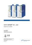
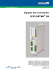
SERVOSTAR 300
Digital Servo Amplifier
Instructions Manual
Translation of the original instructions.
Edition 09/2011
Valid for Hardware Revision 04.00
Keep all manuals as a product component
during the life span of the product.
Pass all manuals to future users / owners
of the product.
File sr300_e.***
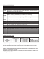
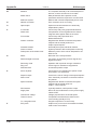
Record of Document Revisions:
Revision
06/2004
04/2005
04/2005a
11/2005
12/2005
02/2006
05/2006
09/2006
03/2007
07/2007
10/2007
05/2008
06/2008
10/2008
02/2009
05/2010
07/2010
11/2010
12/2010
05/2011
09/2011
Remarks
First edition
Restart lock -AS-, UL-listing, new pinning for X8, several corrections
order numbers 400V types for NA updated
Chapter 1 updated, ComCoder wiring corrected, Acuro(BISS)-Interface new, max. station address changed to 127, motor choke changed, SynqNet and EtherCAT expansion cards added,
chapter 6 restructured, order codes restructured
Feedback section, termination resistors X1/X5, CE section
Error messages and warnings updated, additional information (SERCOS), AWG cross-sections
added, inch dimensions added, analog-in circuit updated, cross section (awg)
CAN baud rate coding updated, LED display structure updated, input analog-in updated, BISS interface updated, hardware revision added, Errors/Warnings updated
New document structure, new cover design, warning n24, Quickstart integrated
New part number scheme, termination resistors CAN interface and X5 corrected, branding updated, chapter leakance current new, chapter "servo system graphics" expanded and moved, chapter "various mains supply networks" moved, trouble shooting reduced, Feedback expanded and
restructured, enc emulation, DC-Link expanded, AS restructured, accessories removed
Timing diagramm motor brake, standards updated (EMC and LVD)
Target group, use as directed, standards
Safety symbols acc. to ANSI Z535.6, repair, deinstallation, dU/dt info, syntax: "regen" => "brake",
techn. data connectors, cable requirements, data brake circuit
EC Declaration new, Hiperface corrected, option FAN new
SCCR -> 42kA
Product brand, single phase operation, repair/disposal request form
SSI input clock signal inverted, Gost-R, CE, FAN, AS->STO, Emergency Stop samples=>WIKI
Wiki links updated
New CPU, Ethercat Interface
New company name and address, CE certificate, name plate, fax form
Option EF new, BiSS C, BiSS analog/digital separated, nameplate, front label
Permitted switch on/off frequency defined, unsupported Feedbacks 25/26 removed, certificates
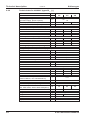
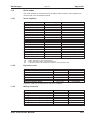
Hardware Revision (HR) History
Hardware Revision
02.01
02.10 (03.01)
04.00
usable
Firmware Revision
³ 2.18
³ 3.75
³ 5.18
usable
DRIVEGUI.EXE Revision
³ 1.30 Build 0056
³ 2.00 Build 0074
³ 2.20 Build 0004
Remarks
Start HWR
AS->STO, new approval
New CPU, front label S300
WINDOWS is a registered trademark of Microsoft Corp.
HIPERFACE is a registered trademark of Max Stegmann GmbH
EnDat is a registered trademark of Dr. Johannes Heidenhain GmbH
EtherCAT is a registered trademark and patented technology, licensed by Beckhoff Automation GmbH
Technical changes which improve the performance of the device may be made without prior notice!
Printed in the Federal Republic of Germany
All rights reserved. No part of this work may be reproduced in any form (by photocopying, microfilm or any
other method) or stored, processed, copied or distributed by electronic means without the written permission
of Kollmorgen Europe GmbH.
Kollmorgen
09/2011
Contents
page
1
General
About this manual . . . . . . . . . . . . . . . . . . . . . . . . . . . . . . . . . . . . . . . . . . . . . . . . . . . . . . . . . . . . . . . .7
Target group . . . . . . . . . . . . . . . . . . . . . . . . . . . . . . . . . . . . . . . . . . . . . . . . . . . . . . . . . . . . . . . . . . . .7
Hints for the online edition (PDF format) . . . . . . . . . . . . . . . . . . . . . . . . . . . . . . . . . . . . . . . . . . . . . .7
Abbreviations used . . . . . . . . . . . . . . . . . . . . . . . . . . . . . . . . . . . . . . . . . . . . . . . . . . . . . . . . . . . . . . .8
Symboles used . . . . . . . . . . . . . . . . . . . . . . . . . . . . . . . . . . . . . . . . . . . . . . . . . . . . . . . . . . . . . . . . . .9
Standards used. . . . . . . . . . . . . . . . . . . . . . . . . . . . . . . . . . . . . . . . . . . . . . . . . . . . . . . . . . . . . . . . . .9
Safety
2.1 Safety Instructions . . . . . . . . . . . . . . . . . . . . . . . . . . . . . . . . . . . . . . . . . . . . . . . . . . . . . . . . . . . . . .10
2.2 Use as directed. . . . . . . . . . . . . . . . . . . . . . . . . . . . . . . . . . . . . . . . . . . . . . . . . . . . . . . . . . . . . . . . .11
2.3 Prohibited use. . . . . . . . . . . . . . . . . . . . . . . . . . . . . . . . . . . . . . . . . . . . . . . . . . . . . . . . . . . . . . . . . .12
Approvals
3.1 Conformance with UL and cUL . . . . . . . . . . . . . . . . . . . . . . . . . . . . . . . . . . . . . . . . . . . . . . . . . . . .13
3.2 EC Conformance . . . . . . . . . . . . . . . . . . . . . . . . . . . . . . . . . . . . . . . . . . . . . . . . . . . . . . . . . . . . . . .14
3.2.1
European Directives and Standards for the machine builder . . . . . . . . . . . . . . . . . . . . . . . . . 14
3.2.2
EC Declaration of Conformity . . . . . . . . . . . . . . . . . . . . . . . . . . . . . . . . . . . . . . . . . . . . . . . . .15
3.3 GOST-R conformance . . . . . . . . . . . . . . . . . . . . . . . . . . . . . . . . . . . . . . . . . . . . . . . . . . . . . . . . . . .16
Handling
4.1 Transport . . . . . . . . . . . . . . . . . . . . . . . . . . . . . . . . . . . . . . . . . . . . . . . . . . . . . . . . . . . . . . . . . . . . .17
4.2 Packaging . . . . . . . . . . . . . . . . . . . . . . . . . . . . . . . . . . . . . . . . . . . . . . . . . . . . . . . . . . . . . . . . . . . . .17
4.3 Storage . . . . . . . . . . . . . . . . . . . . . . . . . . . . . . . . . . . . . . . . . . . . . . . . . . . . . . . . . . . . . . . . . . . . . . .17
4.4 Maintenance, Cleaning. . . . . . . . . . . . . . . . . . . . . . . . . . . . . . . . . . . . . . . . . . . . . . . . . . . . . . . . . . .17
4.5 Disassembling . . . . . . . . . . . . . . . . . . . . . . . . . . . . . . . . . . . . . . . . . . . . . . . . . . . . . . . . . . . . . . . . .18
4.6 Repair . . . . . . . . . . . . . . . . . . . . . . . . . . . . . . . . . . . . . . . . . . . . . . . . . . . . . . . . . . . . . . . . . . . . . . . .18
4.7 Disposal . . . . . . . . . . . . . . . . . . . . . . . . . . . . . . . . . . . . . . . . . . . . . . . . . . . . . . . . . . . . . . . . . . . . . .18
Package
5.1 Package supplied . . . . . . . . . . . . . . . . . . . . . . . . . . . . . . . . . . . . . . . . . . . . . . . . . . . . . . . . . . . . . . .19
5.2 Nameplate . . . . . . . . . . . . . . . . . . . . . . . . . . . . . . . . . . . . . . . . . . . . . . . . . . . . . . . . . . . . . . . . . . . .19
5.3 Part number scheme . . . . . . . . . . . . . . . . . . . . . . . . . . . . . . . . . . . . . . . . . . . . . . . . . . . . . . . . . . . .20
Technical description
6.1 The S300 family of digital servo amplifiers. . . . . . . . . . . . . . . . . . . . . . . . . . . . . . . . . . . . . . . . . . . .21
6.2 Technical data . . . . . . . . . . . . . . . . . . . . . . . . . . . . . . . . . . . . . . . . . . . . . . . . . . . . . . . . . . . . . . . . .23
6.2.1
Technical data for 110/230 V (types S3_ _6_) . . . . . . . . . . . . . . . . . . . . . . . . . . . . . . . . . . . .23
6.2.2
Technical data for 400/480 V (types S3_ _0_) . . . . . . . . . . . . . . . . . . . . . . . . . . . . . . . . . . . .24
6.2.3
Inputs / outputs, Auxiliary voltage . . . . . . . . . . . . . . . . . . . . . . . . . . . . . . . . . . . . . . . . . . . . . .25
6.2.4
Connectors . . . . . . . . . . . . . . . . . . . . . . . . . . . . . . . . . . . . . . . . . . . . . . . . . . . . . . . . . . . . . . .25
6.2.5
Recommended tightening torques . . . . . . . . . . . . . . . . . . . . . . . . . . . . . . . . . . . . . . . . . . . . .25
6.2.6
Fusing . . . . . . . . . . . . . . . . . . . . . . . . . . . . . . . . . . . . . . . . . . . . . . . . . . . . . . . . . . . . . . . . . . .25
6.2.7
Ambient conditions, ventilation, mounting position . . . . . . . . . . . . . . . . . . . . . . . . . . . . . . . . . 26
6.2.8
Conductor cross-sections . . . . . . . . . . . . . . . . . . . . . . . . . . . . . . . . . . . . . . . . . . . . . . . . . . . .26
6.3 Motor holding brake . . . . . . . . . . . . . . . . . . . . . . . . . . . . . . . . . . . . . . . . . . . . . . . . . . . . . . . . . . . . .27
6.4 LED display. . . . . . . . . . . . . . . . . . . . . . . . . . . . . . . . . . . . . . . . . . . . . . . . . . . . . . . . . . . . . . . . . . . .28
6.5 Grounding system . . . . . . . . . . . . . . . . . . . . . . . . . . . . . . . . . . . . . . . . . . . . . . . . . . . . . . . . . . . . . .28
6.6 Dynamic braking (brake circuit) . . . . . . . . . . . . . . . . . . . . . . . . . . . . . . . . . . . . . . . . . . . . . . . . . . . .28
6.7 Switch-on and switch-off behavior . . . . . . . . . . . . . . . . . . . . . . . . . . . . . . . . . . . . . . . . . . . . . . . . . .30
6.7.1
Behavior in standard operation . . . . . . . . . . . . . . . . . . . . . . . . . . . . . . . . . . . . . . . . . . . . . . . .31
6.7.2
Behavior in the event of an error (with standard setting) . . . . . . . . . . . . . . . . . . . . . . . . . . . . 32
6.8 Stop- / Emergency Stop- Function to IEC 60204 . . . . . . . . . . . . . . . . . . . . . . . . . . . . . . . . . . . . . . .33
6.8.1
Stop: Standards. . . . . . . . . . . . . . . . . . . . . . . . . . . . . . . . . . . . . . . . . . . . . . . . . . . . . . . . . . . .33
6.8.2
Emergency Stop: Standards . . . . . . . . . . . . . . . . . . . . . . . . . . . . . . . . . . . . . . . . . . . . . . . . . .34
6.9 Safety function STO . . . . . . . . . . . . . . . . . . . . . . . . . . . . . . . . . . . . . . . . . . . . . . . . . . . . . . . . . . . . .35
6.9.1
Safety characteristic data . . . . . . . . . . . . . . . . . . . . . . . . . . . . . . . . . . . . . . . . . . . . . . . . . . . .35
6.9.2
Safety instructions . . . . . . . . . . . . . . . . . . . . . . . . . . . . . . . . . . . . . . . . . . . . . . . . . . . . . . . . . .36
6.9.3
Use as directed . . . . . . . . . . . . . . . . . . . . . . . . . . . . . . . . . . . . . . . . . . . . . . . . . . . . . . . . . . . .36
6.9.4
Prohibited Use . . . . . . . . . . . . . . . . . . . . . . . . . . . . . . . . . . . . . . . . . . . . . . . . . . . . . . . . . . . . .36
6.9.5
Technical data and pinning . . . . . . . . . . . . . . . . . . . . . . . . . . . . . . . . . . . . . . . . . . . . . . . . . . .37
6.9.6
Enlosure . . . . . . . . . . . . . . . . . . . . . . . . . . . . . . . . . . . . . . . . . . . . . . . . . . . . . . . . . . . . . . . . .37
6.9.7
Wiring . . . . . . . . . . . . . . . . . . . . . . . . . . . . . . . . . . . . . . . . . . . . . . . . . . . . . . . . . . . . . . . . . . .37
6.9.8
Functional description . . . . . . . . . . . . . . . . . . . . . . . . . . . . . . . . . . . . . . . . . . . . . . . . . . . . . . .38
6.9.8.1 Signal diagram (sequence) . . . . . . . . . . . . . . . . . . . . . . . . . . . . . . . . . . . . . . . . . . . . . . . .39
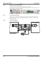
6.9.8.2 Control circuit . . . . . . . . . . . . . . . . . . . . . . . . . . . . . . . . . . . . . . . . . . . . . . . . . . . . . . . . . .40
6.9.8.3 Functional test . . . . . . . . . . . . . . . . . . . . . . . . . . . . . . . . . . . . . . . . . . . . . . . . . . . . . . . . . .41
6.9.8.4 Mains supply circuit. . . . . . . . . . . . . . . . . . . . . . . . . . . . . . . . . . . . . . . . . . . . . . . . . . . . . .41
1.1
1.2
1.3
1.4
1.5
1.6
2
3
4
5
6
S300 Instructions Manual
3
Contents
09/2011
Kollmorgen
page
6.10 Shock-hazard protection. . . . . . . . . . . . . . . . . . . . . . . . . . . . . . . . . . . . . . . . . . . . . . . . . . . . . . . . . .42
6.10.1 Leakage current . . . . . . . . . . . . . . . . . . . . . . . . . . . . . . . . . . . . . . . . . . . . . . . . . . . . . . . . . . .42
6.10.2 Residual current protective device (RCD). . . . . . . . . . . . . . . . . . . . . . . . . . . . . . . . . . . . . . . .42
6.10.3 Isolating transformers . . . . . . . . . . . . . . . . . . . . . . . . . . . . . . . . . . . . . . . . . . . . . . . . . . . . . . .42
7
Mechanical Installation
7.1 Safety Instructions . . . . . . . . . . . . . . . . . . . . . . . . . . . . . . . . . . . . . . . . . . . . . . . . . . . . . . . . . . . . . .43
7.2 Guide to mechanical installation. . . . . . . . . . . . . . . . . . . . . . . . . . . . . . . . . . . . . . . . . . . . . . . . . . . .43
7.3 Assembly . . . . . . . . . . . . . . . . . . . . . . . . . . . . . . . . . . . . . . . . . . . . . . . . . . . . . . . . . . . . . . . . . . . . .44
7.4 Dimensions . . . . . . . . . . . . . . . . . . . . . . . . . . . . . . . . . . . . . . . . . . . . . . . . . . . . . . . . . . . . . . . . . . . .45
8
Electrical installation
8.1 Safety Instructions . . . . . . . . . . . . . . . . . . . . . . . . . . . . . . . . . . . . . . . . . . . . . . . . . . . . . . . . . . . . . .47
8.2 Guide to electrical installation. . . . . . . . . . . . . . . . . . . . . . . . . . . . . . . . . . . . . . . . . . . . . . . . . . . . . .48
8.3 Wiring . . . . . . . . . . . . . . . . . . . . . . . . . . . . . . . . . . . . . . . . . . . . . . . . . . . . . . . . . . . . . . . . . . . . . . . .49
8.3.1
Safety instructions . . . . . . . . . . . . . . . . . . . . . . . . . . . . . . . . . . . . . . . . . . . . . . . . . . . . . . . . . .49
8.3.2
Shielding connection to the front panel . . . . . . . . . . . . . . . . . . . . . . . . . . . . . . . . . . . . . . . . . .50
8.3.3
Technical data for connecting cables . . . . . . . . . . . . . . . . . . . . . . . . . . . . . . . . . . . . . . . . . . .51
8.4 Components of a servo system . . . . . . . . . . . . . . . . . . . . . . . . . . . . . . . . . . . . . . . . . . . . . . . . . . . .52
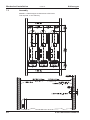
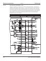
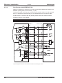
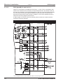
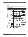
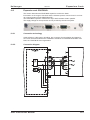
8.5 Block diagram . . . . . . . . . . . . . . . . . . . . . . . . . . . . . . . . . . . . . . . . . . . . . . . . . . . . . . . . . . . . . . . . . .53
8.6 Connector assignments . . . . . . . . . . . . . . . . . . . . . . . . . . . . . . . . . . . . . . . . . . . . . . . . . . . . . . . . . .54
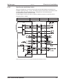
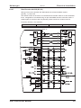
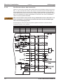
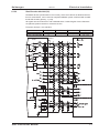
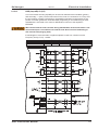
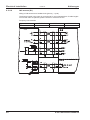
8.7 Connection diagram (Overview) . . . . . . . . . . . . . . . . . . . . . . . . . . . . . . . . . . . . . . . . . . . . . . . . . . . .55
8.8 Electrical supply . . . . . . . . . . . . . . . . . . . . . . . . . . . . . . . . . . . . . . . . . . . . . . . . . . . . . . . . . . . . . . . .56
8.8.1
Connection to various mains supply networks . . . . . . . . . . . . . . . . . . . . . . . . . . . . . . . . . . . .56
8.8.2
24V auxiliary supply (X4). . . . . . . . . . . . . . . . . . . . . . . . . . . . . . . . . . . . . . . . . . . . . . . . . . . . .57
8.8.3
Mains supply connection (X0), three phase . . . . . . . . . . . . . . . . . . . . . . . . . . . . . . . . . . . . . .57
8.8.4
Mains supply connection (X0), two phase without neutral . . . . . . . . . . . . . . . . . . . . . . . . . . . 57
8.8.5
Mains supply connection (X0), single phase with neutral . . . . . . . . . . . . . . . . . . . . . . . . . . . . 58
8.9 External brake resistor (X8) . . . . . . . . . . . . . . . . . . . . . . . . . . . . . . . . . . . . . . . . . . . . . . . . . . . . . . .59
8.10 DC bus link (X8) . . . . . . . . . . . . . . . . . . . . . . . . . . . . . . . . . . . . . . . . . . . . . . . . . . . . . . . . . . . . . . . .59
8.11 Motor connection with brake (X9). . . . . . . . . . . . . . . . . . . . . . . . . . . . . . . . . . . . . . . . . . . . . . . . . . .60
8.12 Feedback systems . . . . . . . . . . . . . . . . . . . . . . . . . . . . . . . . . . . . . . . . . . . . . . . . . . . . . . . . . . . . . .61
8.13 Primary and secondary feedback types . . . . . . . . . . . . . . . . . . . . . . . . . . . . . . . . . . . . . . . . . . . . . .62
8.13.1 Resolver (X2) . . . . . . . . . . . . . . . . . . . . . . . . . . . . . . . . . . . . . . . . . . . . . . . . . . . . . . . . . . . . .63
8.13.2 Sine Encoder with BiSS analog (X1). . . . . . . . . . . . . . . . . . . . . . . . . . . . . . . . . . . . . . . . . . . .64
8.13.3 Sine Encoder with BiSS digital (X1) . . . . . . . . . . . . . . . . . . . . . . . . . . . . . . . . . . . . . . . . . . . .65
8.13.4 Sine Encoder with EnDat 2.1 (X1) . . . . . . . . . . . . . . . . . . . . . . . . . . . . . . . . . . . . . . . . . . . . .66
8.13.5 Sine Encoder with EnDat 2.2 (X1) . . . . . . . . . . . . . . . . . . . . . . . . . . . . . . . . . . . . . . . . . . . . .67
8.13.6 Sine Encoder with HIPERFACE (X1) . . . . . . . . . . . . . . . . . . . . . . . . . . . . . . . . . . . . . . . . . . .68
8.13.7 Sine Encoder with SSI (X5, X1) . . . . . . . . . . . . . . . . . . . . . . . . . . . . . . . . . . . . . . . . . . . . . . .69
8.13.8 Sine Encoder without data channel (X1). . . . . . . . . . . . . . . . . . . . . . . . . . . . . . . . . . . . . . . . .70
8.13.9 Sine Encoder with Hall (X1) . . . . . . . . . . . . . . . . . . . . . . . . . . . . . . . . . . . . . . . . . . . . . . . . . .71
8.13.10 ROD (AquadB) 5V, 1.5 MHz (X1) . . . . . . . . . . . . . . . . . . . . . . . . . . . . . . . . . . . . . . . . . . . . . .72
8.13.11 ROD (AquadB) 5V, 350 kHz (X1) . . . . . . . . . . . . . . . . . . . . . . . . . . . . . . . . . . . . . . . . . . . . . .73
8.13.12 ROD (AquadB) 5V with Hall (X1) . . . . . . . . . . . . . . . . . . . . . . . . . . . . . . . . . . . . . . . . . . . . . .74
8.13.13 ROD (AquadB) 5V (X5) . . . . . . . . . . . . . . . . . . . . . . . . . . . . . . . . . . . . . . . . . . . . . . . . . . . . . .75
8.13.14 ROD (AquadB) 5V with Hall (X5, X1) . . . . . . . . . . . . . . . . . . . . . . . . . . . . . . . . . . . . . . . . . . .76
8.13.15 ROD (AquadB) 24V (X3) . . . . . . . . . . . . . . . . . . . . . . . . . . . . . . . . . . . . . . . . . . . . . . . . . . . . .77
8.13.16 ROD (AquadB) 24V with Hall (X3, X1) . . . . . . . . . . . . . . . . . . . . . . . . . . . . . . . . . . . . . . . . . .78
8.13.17 SSI Encoder (X5, X1) . . . . . . . . . . . . . . . . . . . . . . . . . . . . . . . . . . . . . . . . . . . . . . . . . . . . . . .79
8.13.18 Hall sensors (X1). . . . . . . . . . . . . . . . . . . . . . . . . . . . . . . . . . . . . . . . . . . . . . . . . . . . . . . . . . .80
8.14 Electronic Gearing, Master-slave operation . . . . . . . . . . . . . . . . . . . . . . . . . . . . . . . . . . . . . . . . . . .81
8.14.1 Signal source. . . . . . . . . . . . . . . . . . . . . . . . . . . . . . . . . . . . . . . . . . . . . . . . . . . . . . . . . . . . . .81
8.14.2 Connection to stepper motor controllers (step and direction) . . . . . . . . . . . . . . . . . . . . . . . . . 82
8.14.2.1 Step/Direction 5V, 1.5 MHz (X1) . . . . . . . . . . . . . . . . . . . . . . . . . . . . . . . . . . . . . . . . . . . .82
8.14.2.2 Step/Direction 24V, 100 kHz (X3) . . . . . . . . . . . . . . . . . . . . . . . . . . . . . . . . . . . . . . . . . . .82
8.14.2.3 Step/Direction 5V, 1.5 MHz (X5) . . . . . . . . . . . . . . . . . . . . . . . . . . . . . . . . . . . . . . . . . . . .83
8.14.3 Master-Slave Connection . . . . . . . . . . . . . . . . . . . . . . . . . . . . . . . . . . . . . . . . . . . . . . . . . . . .84
8.14.3.1 Master Slave 5V (X1) . . . . . . . . . . . . . . . . . . . . . . . . . . . . . . . . . . . . . . . . . . . . . . . . . . . .84
8.14.3.2 Master Slave 5V (X5) . . . . . . . . . . . . . . . . . . . . . . . . . . . . . . . . . . . . . . . . . . . . . . . . . . . .84
8.15 Encoder emulation . . . . . . . . . . . . . . . . . . . . . . . . . . . . . . . . . . . . . . . . . . . . . . . . . . . . . . . . . . . . . .85
8.15.1 Incremental encoder output - A quad B (X5) . . . . . . . . . . . . . . . . . . . . . . . . . . . . . . . . . . . . .85
8.15.2 SSI encoder output (X5) . . . . . . . . . . . . . . . . . . . . . . . . . . . . . . . . . . . . . . . . . . . . . . . . . . . . .86
4
S300 Instructions Manual
Kollmorgen
09/2011
Contents
page
8.16 Digital and analog inputs and outputs . . . . . . . . . . . . . . . . . . . . . . . . . . . . . . . . . . . . . . . . . . . . . . .87
8.16.1 Analog inputs (X3). . . . . . . . . . . . . . . . . . . . . . . . . . . . . . . . . . . . . . . . . . . . . . . . . . . . . . . . . .87
8.16.2 Digital inputs (X3/X4). . . . . . . . . . . . . . . . . . . . . . . . . . . . . . . . . . . . . . . . . . . . . . . . . . . . . . . .88
8.16.3 Digital outputs (X3) . . . . . . . . . . . . . . . . . . . . . . . . . . . . . . . . . . . . . . . . . . . . . . . . . . . . . . . . .89
8.17 RS232 interface, PC connection (X6) . . . . . . . . . . . . . . . . . . . . . . . . . . . . . . . . . . . . . . . . . . . . . . .90
8.18 CANopen interface (X6) . . . . . . . . . . . . . . . . . . . . . . . . . . . . . . . . . . . . . . . . . . . . . . . . . . . . . . . . . .91
9
Setup
9.1 Safety Instructions . . . . . . . . . . . . . . . . . . . . . . . . . . . . . . . . . . . . . . . . . . . . . . . . . . . . . . . . . . . . . .93
9.2 Setup software . . . . . . . . . . . . . . . . . . . . . . . . . . . . . . . . . . . . . . . . . . . . . . . . . . . . . . . . . . . . . . . . .94
9.2.1
General . . . . . . . . . . . . . . . . . . . . . . . . . . . . . . . . . . . . . . . . . . . . . . . . . . . . . . . . . . . . . . . . . .94
9.2.1.1 Use as directed . . . . . . . . . . . . . . . . . . . . . . . . . . . . . . . . . . . . . . . . . . . . . . . . . . . . . . . . .94
9.2.1.2 Software description . . . . . . . . . . . . . . . . . . . . . . . . . . . . . . . . . . . . . . . . . . . . . . . . . . . . .94
9.2.1.3 Hardware requirements. . . . . . . . . . . . . . . . . . . . . . . . . . . . . . . . . . . . . . . . . . . . . . . . . . .95
9.2.1.4 Operating systems . . . . . . . . . . . . . . . . . . . . . . . . . . . . . . . . . . . . . . . . . . . . . . . . . . . . . .95
9.2.2
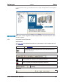
Installation under WINDOWS . . . . . . . . . . . . . . . . . . . . . . . . . . . . . . . . . . . . . . . . . . . . . . . . .95
9.3 Quickstart . . . . . . . . . . . . . . . . . . . . . . . . . . . . . . . . . . . . . . . . . . . . . . . . . . . . . . . . . . . . . . . . . . . . .96
9.3.1
Preparation . . . . . . . . . . . . . . . . . . . . . . . . . . . . . . . . . . . . . . . . . . . . . . . . . . . . . . . . . . . . . . .96
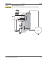
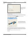
9.3.1.1 Unpacking, Mounting and Wiring the Servo Amplifier . . . . . . . . . . . . . . . . . . . . . . . . . . . 96
9.3.1.2 Documents . . . . . . . . . . . . . . . . . . . . . . . . . . . . . . . . . . . . . . . . . . . . . . . . . . . . . . . . . . . .96
9.3.1.3 Minimum Wiring for Drive Test . . . . . . . . . . . . . . . . . . . . . . . . . . . . . . . . . . . . . . . . . . . . .97
9.3.2
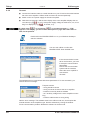
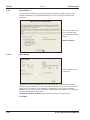
Connect . . . . . . . . . . . . . . . . . . . . . . . . . . . . . . . . . . . . . . . . . . . . . . . . . . . . . . . . . . . . . . . . . .98
9.3.3
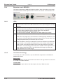
Important Screen Elements. . . . . . . . . . . . . . . . . . . . . . . . . . . . . . . . . . . . . . . . . . . . . . . . . . .99
9.3.4
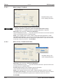
Setup Wizard . . . . . . . . . . . . . . . . . . . . . . . . . . . . . . . . . . . . . . . . . . . . . . . . . . . . . . . . . . . . .100
9.3.4.1 Basic Setup . . . . . . . . . . . . . . . . . . . . . . . . . . . . . . . . . . . . . . . . . . . . . . . . . . . . . . . . . . .100
9.3.4.2 Units/Mechanical . . . . . . . . . . . . . . . . . . . . . . . . . . . . . . . . . . . . . . . . . . . . . . . . . . . . . . .101
9.3.4.3 Motor (rotary) / Feedback . . . . . . . . . . . . . . . . . . . . . . . . . . . . . . . . . . . . . . . . . . . . . . . .102
9.3.4.4 Motor (linear) / Feedback (Encoder) . . . . . . . . . . . . . . . . . . . . . . . . . . . . . . . . . . . . . . . .102
9.3.4.5 Save Parameters and Restart. . . . . . . . . . . . . . . . . . . . . . . . . . . . . . . . . . . . . . . . . . . . .103
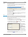
9.3.5
Motion Service (Jog Mode) . . . . . . . . . . . . . . . . . . . . . . . . . . . . . . . . . . . . . . . . . . . . . . . . . .103
9.3.6
More Setup Screens . . . . . . . . . . . . . . . . . . . . . . . . . . . . . . . . . . . . . . . . . . . . . . . . . . . . . . .104
9.4 Multi-axis system . . . . . . . . . . . . . . . . . . . . . . . . . . . . . . . . . . . . . . . . . . . . . . . . . . . . . . . . . . . . . .105
9.4.1
Station address for CAN-bus . . . . . . . . . . . . . . . . . . . . . . . . . . . . . . . . . . . . . . . . . . . . . . . .105
9.4.2
Baud rate for CAN-bus . . . . . . . . . . . . . . . . . . . . . . . . . . . . . . . . . . . . . . . . . . . . . . . . . . . . .105
9.5 Keypad operation / LED display . . . . . . . . . . . . . . . . . . . . . . . . . . . . . . . . . . . . . . . . . . . . . . . . . . .105
9.5.1
Keypad operation . . . . . . . . . . . . . . . . . . . . . . . . . . . . . . . . . . . . . . . . . . . . . . . . . . . . . . . . .106
9.5.2
Status display . . . . . . . . . . . . . . . . . . . . . . . . . . . . . . . . . . . . . . . . . . . . . . . . . . . . . . . . . . . .106
9.5.3
Standard menu . . . . . . . . . . . . . . . . . . . . . . . . . . . . . . . . . . . . . . . . . . . . . . . . . . . . . . . . . . .106
9.5.4
Advanced menu . . . . . . . . . . . . . . . . . . . . . . . . . . . . . . . . . . . . . . . . . . . . . . . . . . . . . . . . . .107
9.6 Error messages . . . . . . . . . . . . . . . . . . . . . . . . . . . . . . . . . . . . . . . . . . . . . . . . . . . . . . . . . . . . . . .108
9.7 Warning messages. . . . . . . . . . . . . . . . . . . . . . . . . . . . . . . . . . . . . . . . . . . . . . . . . . . . . . . . . . . . .109
9.8 Trouble Shooting . . . . . . . . . . . . . . . . . . . . . . . . . . . . . . . . . . . . . . . . . . . . . . . . . . . . . . . . . . . . . .110
S300 Instructions Manual
5
Contents
09/2011
Kollmorgen
page
10
Expansions Cards
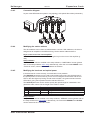
10.1 Guide to installation of expansion cards. . . . . . . . . . . . . . . . . . . . . . . . . . . . . . . . . . . . . . . . . . . . .111
10.2 Expansion card -I/O-14/08- . . . . . . . . . . . . . . . . . . . . . . . . . . . . . . . . . . . . . . . . . . . . . . . . . . . . . .112
10.2.1 Technical data . . . . . . . . . . . . . . . . . . . . . . . . . . . . . . . . . . . . . . . . . . . . . . . . . . . . . . . . . . . .112
10.2.2 LEDs . . . . . . . . . . . . . . . . . . . . . . . . . . . . . . . . . . . . . . . . . . . . . . . . . . . . . . . . . . . . . . . . . . .112
10.2.3 Entering a motion block number (example) . . . . . . . . . . . . . . . . . . . . . . . . . . . . . . . . . . . . .112
10.2.4 Connector assignments . . . . . . . . . . . . . . . . . . . . . . . . . . . . . . . . . . . . . . . . . . . . . . . . . . . .113
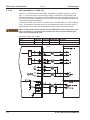
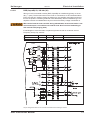
10.2.5 Connection diagram (default) . . . . . . . . . . . . . . . . . . . . . . . . . . . . . . . . . . . . . . . . . . . . . . . .114
10.3 Expansion card -PROFIBUS- . . . . . . . . . . . . . . . . . . . . . . . . . . . . . . . . . . . . . . . . . . . . . . . . . . . . .115
10.3.1 Connection technology . . . . . . . . . . . . . . . . . . . . . . . . . . . . . . . . . . . . . . . . . . . . . . . . . . . . .115
10.3.2 Connection diagram . . . . . . . . . . . . . . . . . . . . . . . . . . . . . . . . . . . . . . . . . . . . . . . . . . . . . . .115
10.4 Expansion card -SERCOS- . . . . . . . . . . . . . . . . . . . . . . . . . . . . . . . . . . . . . . . . . . . . . . . . . . . . . .116
10.4.1 LEDs . . . . . . . . . . . . . . . . . . . . . . . . . . . . . . . . . . . . . . . . . . . . . . . . . . . . . . . . . . . . . . . . . . .116
10.4.2 Connection technology . . . . . . . . . . . . . . . . . . . . . . . . . . . . . . . . . . . . . . . . . . . . . . . . . . . . .116
10.4.3 Connection diagram . . . . . . . . . . . . . . . . . . . . . . . . . . . . . . . . . . . . . . . . . . . . . . . . . . . . . . .117
10.4.4 Modifying the station address . . . . . . . . . . . . . . . . . . . . . . . . . . . . . . . . . . . . . . . . . . . . . . . .117
10.4.5 Modifying the baud rate and optical power . . . . . . . . . . . . . . . . . . . . . . . . . . . . . . . . . . . . . .117
10.5 Expansion card -DEVICENET-. . . . . . . . . . . . . . . . . . . . . . . . . . . . . . . . . . . . . . . . . . . . . . . . . . . .118
10.5.1 Connection technology . . . . . . . . . . . . . . . . . . . . . . . . . . . . . . . . . . . . . . . . . . . . . . . . . . . . .118
10.5.2 Connection diagram . . . . . . . . . . . . . . . . . . . . . . . . . . . . . . . . . . . . . . . . . . . . . . . . . . . . . . .118
10.5.3 Combined module/network status-LED . . . . . . . . . . . . . . . . . . . . . . . . . . . . . . . . . . . . . . . .119
10.5.4 Setting the station address (device address) . . . . . . . . . . . . . . . . . . . . . . . . . . . . . . . . . . . .119
10.5.5 Setting the transmission speed . . . . . . . . . . . . . . . . . . . . . . . . . . . . . . . . . . . . . . . . . . . . . . .119
10.5.6 Bus cable. . . . . . . . . . . . . . . . . . . . . . . . . . . . . . . . . . . . . . . . . . . . . . . . . . . . . . . . . . . . . . . .120
10.6 Expansion card -SYNQNET- . . . . . . . . . . . . . . . . . . . . . . . . . . . . . . . . . . . . . . . . . . . . . . . . . . . . .121
10.6.1 NODE ID Switch . . . . . . . . . . . . . . . . . . . . . . . . . . . . . . . . . . . . . . . . . . . . . . . . . . . . . . . . . .121
10.6.2 Node LED table . . . . . . . . . . . . . . . . . . . . . . . . . . . . . . . . . . . . . . . . . . . . . . . . . . . . . . . . . .121
10.6.3 SynqNet Connection, Connector X21B/C (RJ-45) . . . . . . . . . . . . . . . . . . . . . . . . . . . . . . . . 121
10.6.4 Digital inputs/outputs, connector X21A (SubD 15-pin, socket) . . . . . . . . . . . . . . . . . . . . . . . 122
10.6.5 Connection diagram digital inputs/outputs, connector X21A . . . . . . . . . . . . . . . . . . . . . . . . 122
10.7 Expansion module -2CAN- . . . . . . . . . . . . . . . . . . . . . . . . . . . . . . . . . . . . . . . . . . . . . . . . . . . . . . .123
10.7.1 Installation . . . . . . . . . . . . . . . . . . . . . . . . . . . . . . . . . . . . . . . . . . . . . . . . . . . . . . . . . . . . . . .123
10.7.2 Connection technology . . . . . . . . . . . . . . . . . . . . . . . . . . . . . . . . . . . . . . . . . . . . . . . . . . . . .123
10.7.3 Connector assignments . . . . . . . . . . . . . . . . . . . . . . . . . . . . . . . . . . . . . . . . . . . . . . . . . . . .124
10.7.4 Connection diagram . . . . . . . . . . . . . . . . . . . . . . . . . . . . . . . . . . . . . . . . . . . . . . . . . . . . . . .124
10.8 Option "EtherCAT" . . . . . . . . . . . . . . . . . . . . . . . . . . . . . . . . . . . . . . . . . . . . . . . . . . . . . . . . . . . . .125
10.8.1 Node LED tabl . . . . . . . . . . . . . . . . . . . . . . . . . . . . . . . . . . . . . . . . . . . . . . . . . . . . . . . . . . . .125
10.8.2 Connection diagram . . . . . . . . . . . . . . . . . . . . . . . . . . . . . . . . . . . . . . . . . . . . . . . . . . . . . . .125
10.9 Option "FAN", ventilator control . . . . . . . . . . . . . . . . . . . . . . . . . . . . . . . . . . . . . . . . . . . . . . . . . . .126
10.10 Option "EF", ventilator control and EtherCAT . . . . . . . . . . . . . . . . . . . . . . . . . . . . . . . . . . . . . . . .126
11
Appendix
11.1 Glossary . . . . . . . . . . . . . . . . . . . . . . . . . . . . . . . . . . . . . . . . . . . . . . . . . . . . . . . . . . . . . . . . . . . . .127
11.2 Order codes . . . . . . . . . . . . . . . . . . . . . . . . . . . . . . . . . . . . . . . . . . . . . . . . . . . . . . . . . . . . . . . . . .129
11.2.1 Servo amplifiers. . . . . . . . . . . . . . . . . . . . . . . . . . . . . . . . . . . . . . . . . . . . . . . . . . . . . . . . . . .129
11.2.2 Expansion cards . . . . . . . . . . . . . . . . . . . . . . . . . . . . . . . . . . . . . . . . . . . . . . . . . . . . . . . . . .129
11.2.3 Mating connectors . . . . . . . . . . . . . . . . . . . . . . . . . . . . . . . . . . . . . . . . . . . . . . . . . . . . . . . . .129
11.3 Repair-/Disposal request Telefax form. . . . . . . . . . . . . . . . . . . . . . . . . . . . . . . . . . . . . . . . . . . . . .130
11.4 Index . . . . . . . . . . . . . . . . . . . . . . . . . . . . . . . . . . . . . . . . . . . . . . . . . . . . . . . . . . . . . . . . . . . . . . . .131
6
S300 Instructions Manual
Kollmorgen
09/2011
1
General
1.1
About this manual
General
This manual describes the S300 series of digital servo amplifiers SERVOSTAR 300
(S300 standard version, 1.5A ...10A rated current).
A more detailed description of the expansion cards that are currently available and the
digital connection to automation systems can be found, together with our applications
notes, in Acrobat-Reader format on the accompanying CD-ROM (system requirements:
WINDOWS, Internet Browser, Acrobat Reader) in different languages.
Technical data and dimensional drawings of accessories such as cables, brake resistors,
mains supplies, etc., can be found in the accessories manual.
This documentation can be printed out on any standard commercial printer. A printed
copy of the documentation is available from us at extra cost.
More background information can be found in the "Product WIKI", please check
www.wiki-kollmorgen.eu.
1.2
Target group
This manual addresses personnel with the following qualifications:
Transport : only by personnel with knowledge of handling electrostatically sensitive
components.
Unpacking: only by electrically qualified personnel.
Installation : only by electrically qualified personnel.
Setup :
only by qualified personnel with extensive knowledge of electrical
engineering and drive technology
The qualified personnel must know and observe the following standards:
IEC 60364 and IEC 60664
national accident prevention regulations
During operation there are deadly hazards, with the possibility of death, severe
injury or material damage. The operator must ensure that the safety instructions in
this manual are followed. The operator must ensure that all personnel responsible
for working with the servo amplifier have read and understood the Instructions
Manual.
1.3
Hints for the online edition (PDF format)
Bookmarks:
Table of contents and index are active bookmarks.
Table of contents and index in the text:
The lines are active cross references. Click on the desired line and the appropriate page
is accessed.
Page/chapter numbers in the text:
Page/chapter numbers with cross references are active. Click at the page/chapter number to reach the indicated target.
S300 Instructions Manual
7
General
1.4
Abbreviations used
Abbrev.
AGND
BTB/RTO
CAN
CE
CLK
COM
DGND
DIN
Disk
EEPROM
EMC
EMI
EN
ESD
F-SMA
IEC
IGBT
INC
ISO
LED
MB
NI
PC
PELV
PLC
PWM
RAM
RBallast / RBR
RBext
RBint
RES
ROD
S1
S3
SRAM
SSI
STO
UL
V AC
V DC
VDE
8
Kollmorgen
09/2011
Meaning
Analog ground
Ready to operate
Fieldbus (CANopen)
Communité Europeenne
Clock signal
Serial interface for a PC-AT
Digital ground (for 24V and digital I/O)
German Institute for Industrial Standards
Magnetic storage (diskette, hard disk)
Electrically erasable programmable memory
Electromagnetic compatibility
Electromagnetic interference
European Standard
Electrostatic discharge
Fiber Optic Cable connector according to IEC 60874-2
International Electrotechnical Commission
Insulated-gate bipolar transistor
Incremental interface
International Organization for Standardization
Light-emitting diode
Megabyte
Zero pulse
Personal computer
Protected low voltage
Programmable logic controller
Pulse-width modulation
Volatile memory
Ballast resistor (= brake resistor or regen resistor)
External brake resistor
Internal brake resistor
Resolver
digital encoder
continuous operation
Intermittent operation
Static RAM
Synchronous serial interface
Safe torque off, restart lock
Underwriters Laboratories
Alternating voltage
DC voltage
Society of German Electrical Technicians
S300 Instructions Manual
Kollmorgen
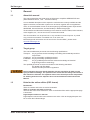
1.5
09/2011
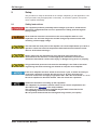
Symboles used
Symbol
1.6
General
Indication
Indicates a hazardous situation which, if not avoided, will result in
death or serious injury.
Indicates a hazardous situation which, if not avoided, could result
in death or serious injury.
Indicates a hazardous situation which, if not avoided, could result
in minor or moderate injury.
Indicates situations which, if not avoided, could result in property
damage.
This is not a safety symbol.
This symbol indicates important notes.
Standards used
Standard
ISO 4762
ISO 11898
ISO 13849
ISO 12100
IEC 60085
IEC 60204
IEC 60364
IEC 60439
IEC 60529
IEC 60664
IEC 60721
IEC 61000
IEC 61131
IEC 61491
IEC 61508
IEC 61800
IEC 62061
IEC 62079
ANSI Z535
UL 840
UL 508C
ANSI
IEC
ISO
UL
Content
Hexagon socket head cap screws
Road vehicles — Controller area network (CAN)
Safety of machinery: Safety-related parts of control systems
Safety of machinery: Basic concepts, general principles for design
Electrical insulation - Thermal evaluation and designation Maintenance
Safety of Machinery: Electrical equipment of machinery
Low-voltage electrical installations
Low-Voltage Switchgear and Controlgear Assemblies
Protection categories by housing (IP Code)
Insulation coordination for equipment within low-voltage systems
Classification of environmental conditions
Electromagnetic compatibility (EMC)
Programmable controllers
Electrical equipment of industrial machines – Serial data link for
real-time communications between controls and drives.
Functional safety of electrical/electronic/programmable electronic
safety-related systems
Adjustable speed electrical power drive systems
Functional safety of electrical/electronic/programmable electronic
safety-related systems
Preparation of instructions - Structuring, content and presentation
Product safety (symbols, colors, information)
UL Standard for Safety for Insulation Coordination Including Clearances
and Creepage Distances for Electrical Equipment
UL Standard for Safety Power Conversion Equipment
American National Standard Institute, Inc.
International Electrotechnical Commission
International Organization for Standardization
Underwriters Laboratories
S300 Instructions Manual
9
Safety
09/2011
2
Safety
2.1
Safety Instructions
Kollmorgen
During operation there are deadly hazards, with the possibility of death, severe
injury or material damage. Do not open or touch the equipment during operation.
Keep all covers and cabinet doors closed during operation. Touching the
equipment is allowed during installation and commissioning for properly qualified
persons only.
—
During operation, servo amplifiers may have uncovered live components,
depending on their level of enclosure protection.
—
Control and power connections may be live, even though the motor is not
rotating.
—
Servo amplifiers may have hot surfaces during operation.
Surface can reach temperatures above 80°C.
There is a danger of electrical arcing with damage to contacts and personal injury.
Never undo any electrical connections to the servo amplifier while it is live.
Wait at least five minutes after disconnecting the servo amplifier from the main
supply power before touching potentially live sections of the equipment (e.g.
contacts) or undoing any connections.
Capacitors can still have dangerous voltages present up to five minutes after
switching off the supply power. To be sure, measure the voltage in the DC Bus link
and wait until it has fallen below 40V.
Incorrect handling of the servo amplifier can lead to personal injury or material
damage. Read this documentation before carrying out the installation and
commissioning. It is vital that you keep to the technical data and information on
connection requirements (nameplate and documentation).
Only properly qualified personnel are permitted to carry out activities such as
transport, installation, commissioning and maintenance. Properly qualified persons
are those who are familiar with the transport, assembly, installation,
commissioning and operation of the product, and who have the appropriate
qualifications for their job. The qualified personnel must know and observe the
following standards:
—
IEC 60364 and IEC 60664
—
national accident prevention regulations
The manufacturer of the machine must produce a risk assessment for the machine
and take appropriate measures to ensure that unforeseen movements do not result
in personal injury or material damage.
Check the Hardware Revision Number of the product (see product label). This
revision number must match the Hardware Revision Number on the cover page of
the manual.
The servo amplifiers contain electrostatically sensitive components which may be
damaged by incorrect handling. Discharge your body before touching the servo
amplifier. Avoid contact with highly insulating materials (artificial fabrics, plastic
film etc.). Place the servo amplifier on a conductive surface.
10
S300 Instructions Manual
Kollmorgen
2.2
09/2011
Safety
Use as directed
Servo amplifiers are safety components that are built into electrical plant or machines,
and can only be operated as integral components of such plant or machines.
The manufacturer of the machine must generate a risk assessment for the machine, and
take appropriate measures to ensure that unforeseen movements cannot cause injury or
damage to any person or property.
If the servo amplifiers are used in residential areas, in business/commercial areas, or in
small industrial operations, then additional filter measures must be implemented by the
user.
Cabinet and Wiring
The servo amplifiers must only be operated in a closed control cabinet, taking into
account the ambient conditions defined on page 26. Ventilation or cooling may be necessary to keep the temperature within the cabinet below 40°C.
Use only copper conductors for wiring. The conductor cross-sections can be derived from
the standard IEC 60204 (alternatively for AWG cross-sections: NEC Table 310-16, 60°C
or 75°C column).
Power supply
Servo amplifiers in the S300 series (overvoltage category III acc. to EN 61800-5-1) can
be supplied from 3-phase grounded (earthed) industrial supply networks (TN-system,
TT-system with grounded neutral point, no more than 42kA symmetrical rated current at
110-10%...230V+10% or 208-10%...480V+10% depending on the amplifier type). Connection
to other types of supply networks (with an additional isolating transformer) is described on
page 56.
Periodic overvoltage between phases (L1, L2, L3) and the housing of the servo amplifier
must not exceed 1000V crest. In accordance with IEC 61800, voltage spikes (< 50µs)
between phases must not exceed 1000V. Voltage spikes (< 50µs) between a phase and
the housing must not exceed 2000V.
Motors
The S300 family of servo amplifiers is exclusively intended for driving suitable brush less
synchronous servomotors or asynchronous motors with control of torque, speed and/or
position.
The rated voltage of the motors must be at least as high as the DC bus link voltage divided by 2 produced by the servo amplifier (UnMotor³ UDC/ 2).
Safety
Observe the chapter "use as directed" on page 36 when you use the safety function STO.
S300 Instructions Manual
11
Safety
2.3
09/2011
Kollmorgen
Prohibited use
Other use than described in chapter 2.2 is not intended and can lead to damage of persons, equipment or things.
The use of the servo amplifier in the following environments is prohibited:
potentially explosive areas
environments with corrosive and/or electrically conductive acids, alkaline solutions,
oils, vapors, dusts
directly on non-grounded supply networks or on asymmetrically grounded supplies
with a voltage >230V.
on ships or off-shore applications
Commissioning the servo amplifier is prohibited if the machine in which it was installed,
does not meet the requirements of the EC Machinery Directive
does not comply with the EMC Directive or with the Low Voltage Directive
does not comply with any national directives
The control of holding brakes by the S300 alone may not be used in applications, where
personnel security is to be ensured with the brake.
12
S300 Instructions Manual
Kollmorgen
3
09/2011
Approvals
Approvals
Certificates can be found in our Product Wiki on page Approvals.
3.1
Conformance with UL and cUL
This servo amplifier is listed under UL file number E217428.
UL (cUL)-certified servo amplifiers (Underwriters Laboratories Inc.) fulfil the relevant U.S.
and Canadian standard (in this case UL 840 and UL 508C).
This standard describes the fulfillment by design of minimum requirements for electrically
operated power conversion equipment, such as frequency converters and servo amplifiers, which is intended to eliminate the risk of fire, electric shock, or injury to persons,
being caused by such equipment. The technical conformance with the U.S. and Canadian
standard is determined by an independent UL (cUL) inspector through the type testing
and regular checkups.
Apart from the notes on installation and safety in the documentation, the customer does
not have to observe any other points in direct connection with the UL (cUL)-certification of
the equipment.
UL 508C
UL 508C describes the fulfillment by design of minimum requirements for electrically operated power conversion equipment, such as frequency converters and servo amplifiers,
which is intended to eliminate the risk of fire being caused by such equipment.
UL 840
UL 840 describes the fulfillment by design of air and insulation creepage spacings for
electrical equipment and printed circuit boards.
UL Markings
l
Use 60/75°C copper wire only for every model of this section.
l
Tightening torque for field wiring terminals see page 25
l
Use in a pollution degree 2 environment.
l
Use Class 1 wire only or equivalent.
l
Suitable for use on a circuit capable of delivering not more than 42kA rms symmetrical amperes for a max. voltage of 480 V.
S300 Instructions Manual
13
Approvals
3.2
Kollmorgen
09/2011
EC Conformance
Conformance with the EC Machine Directive 2006/42/EC, the EC EMC Directive
2004/108/EC and the Low Voltage Directive 2006/95/EC is mandatory for the supply of
servo amplifiers within the European Community.
The servo amplifier meets the noise immunity requirements to the 2nd environmental
category (industrial environment). For noise emission the amplifier meets the requirement
to a product of the category C2 (motor cable £ 10m).
This product can cause high-frequency interferences in non industrial
environments which can require measures for interference suppression.
With a motor cable length of 10m or longer, the servo amplifier meets the requirement to
the category C3.
The servo amplifiers have been tested by an authorized testing laboratory in a defined
configuration, using the system components that are described in this documentation.
Any divergence from the configuration and installation described in this documentation
means that you will be responsible for carrying out new measurements to ensure conformance with regulatory requirements.
3.2.1
European Directives and Standards for the machine builder
Servo amplifiers are safety components that are intended to be incorporated into electrical plant and machines for industrial use. When the servo amplifiers are built into machines or plant, the amplifier must not be used until it has been established that the machine
or equipment fulfills the requirements of the
l
EC Machinery Directive
(2006/42/EC)
l
EC EMC Directive
(2004/108/EC)
l
EC Low Voltage Directive
(2006/95/EC)
Standards to be applied for conformance with the EC Machinery Directive (2006/42/EC)
EN 60204-1 (Safety and Electrical Equipment in Machines)
EN 12100 (Safety of Machines)
The manufacturer of the machine must generate a risk assessment for the
machine, and must implement appropriate measures to ensure that unforeseen
movements cannot cause injury or damage to any person or property.
The machine/plant manufacturer must check whether other standards or EC
Directives must be applied to the machine/plant.
Standards to be applied for conformance with the Low Voltage Directive (2006/95/EC):
EN 60204-1 (Safety and Electrical Equipment in Machines)
EN 60439-1 (Low-voltage switchgear and controlgear assemblies)
Standards to be applied for conformance with the EMC Directive (2004/108/EC):
EN 61000-6-1 / 2 (Interference Immunity in Residential & Industrial Areas)
EN 61000-6-3 / 4 (Interference Generation in Residential & Industrial Areas)
The manufacturer of the machine/plant is responsible for ensuring that it meets the limits
required by the EMC regulations. Advice on the correct installation for EMC can be found
in this documentation.
We only guarantee the conformance of the servo system with the standards cited in this
chapter if the components (motor, cables, chokes etc.) are those supplied by us.
14
S300 Instructions Manual
Kollmorgen
3.2.2
09/2011
Approvals
EC Declaration of Conformity
S300 Instructions Manual
15
Approvals
3.3
Kollmorgen
09/2011
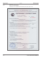
GOST-R conformance
Certificate for servo amplifier and accessories (cover page, page 1 of 3).
16
S300 Instructions Manual
Kollmorgen
09/2011
4
Handling
4.1
Transport
4.2
4.3
4.4
Handling
l
Transport by qualified personnel in the manufacturer’s original recyclable packaging
l
Avoid shocks while transporting
l
Transport temperature:
-25 to +70°C, max. rate of change 20K / hour,
class 2K3 acc. to EN61800-2
l
Transport humidity:
max. 95% relative humidity, no condensation,
class 2K3 acc. to EN61800-2
l
The servo amplifiers contain electrostatically sensitive components, that can
be damaged by incorrect handling. Discharge yourself before touching the servo amplifier. Avoid contact with highly insulating materials, such as artificial
fabrics and plastic films. Place the servo amplifier on a conductive surface.
l
If the packaging is damaged, check the unit for visible damage. In such an event, inform the shipper and the manufacturer.
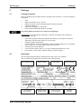
Packaging
l
Recyclable cardboard with inserts
l
Dimensions:
(HxWxD) 115x365x275mm
l
Labeling:
instrument label on outside of box
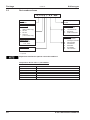
Storage
l
Storage only in the manufacturer’s original recyclable packaging
l
Max. stacking height
8 cartons
l
Storage temperature
-25 to +55°C, max. rate of change 20K / hour,
class 1K4 acc. to EN61800-2
l
Storage humidity
5 ... 95% relative humidity, no condensation,
class 1K3 acc. to EN61800-2
l
Storage duration:
Less than 1 year: without restriction.
More than 1 year: capacitors must be re-formed before setting up and operating the
servo amplifier. To do this, remove all electrical connections and apply single-phase
230V AC for about 30 minutes to the terminals L1 / L2.
Maintenance, Cleaning
The instruments do not require any maintenance, opening the instruments invalidates the
warranty.
Cleaning : — if the casing is dirty: clean with Isopropanol or similar
NOTICE: do not immerse or spray
— Dirt inside the unit: must be cleaned by the manufacturer
— For dirty protective grill on fan: clean with a dry brush
S300 Instructions Manual
17
Handling
4.5
09/2011
Kollmorgen
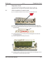
Disassembling
Observe the sequence below, if a servo amplifier has to be disassembled (e.g. for replacement).
1. Electrical disconnection
Switch off the main switch of the switchgear cabinet and the fuses that supply the
system.
Wait at least five minutes after disconnecting the servo amplifier from the main
supply power before touching potentially live sections of the equipment (e.g.
contacts) or undoing any connections. To be sure, measure the voltage in the DC
Bus link and wait until it has fallen below 40V.
Remove the connectors. Disconnect the earth (ground) connection at last.
2. Check temperature
During operation the heat sink of the servo amplifier may reach temperatures
above 80°C (176°F). Before touching the device, check the temperature and wait
until it has cooled down below 40°C (104°F).
3. Disassembling
Disassemble the servo amplifier (reverse of the procedure described in chapter "Mechanical installation).
4.6
Repair
Repair of the servo amplifier must be done by the manufacturer. Opening the devices
means loss of the guarantee. Use the telefax form on page 130 for repair request. You'll
receive the current dispatch information.
Disassemble the equipment as described in chapter 4.5 and send it in the original packaging to the address given in the dispatch information.
4.7
Disposal
In accordance to the WEEE-2002/96/EC-Guidelines we take old devices and accessories
back for professional disposal. Transport costs are the responsibility of the sender. Use
the telefax form on page 130 for disposal request. You'll receive the current dispatch
information.
Disassemble the equipment as described in chapter 4.5 and send it in the original packaging to the address given in the dispatch information.
18
S300 Instructions Manual
Kollmorgen
Package
09/2011
5
Package
5.1
Package supplied
When an amplifier from the S300 series is ordered (order numbers ðp.129), the following
is supplied:
—
—
—
—
—
—
S3xx
Mating connectors X0, X3, X4, X8
Mating connector X9 only with SERVOSTAR 303-310 (S3xx6)
Instructions Manual
Online documentation on CD-ROM
Setup software DRIVEGUI.EXE on CD-ROM
The mating SubD connectors are not part of the package!
Accessories : (must be ordered separately, if required; description see accessories
manual)
—
—
—
—
—
—
5.2
motor cable (prefabricated) with special shield clamp, or both power connectors
separately, with the motor cable as a cut-off length
feedback cable (prefabricated)
or both feedback connectors separately, with the feedback cable as a cut-off length
motor choke 3YL, for motor cables longer than 25 meters
external brake resistor BAR(U)
communication cable to the PC (ð p.90) for setting parameters from a PC
power cable, control cables, fieldbus cables (as cut-off lengths)
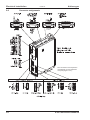
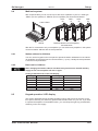
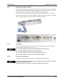
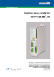
Nameplate
The nameplate depicted below is attached to the side of the servo amplifier.
The information described below is printed in the individual fields.
Servo amplifier type
Serial number
Comments
Enclosure Rating
max. ambient
temperature
Electrical supply
Installed load
Output current
in S1 operation
Hardware
Revision
S300 Instructions Manual
19
Package
5.3
Kollmorgen
09/2011
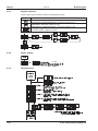
Part number scheme
S 3 0 6 0 1 - S E - zzz
Family
S3
S300
Customer specific
specials
Current rating
01 1.5A rms
(208 to 480V only)
03 3A rms
06 6A rms
10 10A rms
(110 to 230V only)
Device Options
NA
Base device
FN
controlled FAN
EC
EtherCAT
EF* FAN & EtherCAT
Expansions
NA
no expansion,
CANopen onboard
DN
DEVICENET
PB
PROFIBUS
SE
SERCOS
SQ
SYNQNET
I/O
I/O Extension
Voltage rating
0
208...480V
6
110...230V
Electr. options
1
STO
*= in process
Expansions and Device Options cannot be combined.
Comparison device name -> part number
Device Name
SERVOSTAR 303
SERVOSTAR 306
SERVOSTAR 310
SERVOSTAR 341
SERVOSTAR 343
SERVOSTAR 346
20
Part Number
S30361-NA
S30661-NA
S31061-NA
S30101-NA
S30301-NA
S30601-NA
S300 Instructions Manual
Kollmorgen
09/2011
6
Technical description
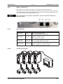
6.1
The S300 family of digital servo amplifiers
Technical description
Standard version
l
Two voltage classes with large nominal voltage range
1 x 110V-10% ... 3 x 230V+10% (SERVOSTAR 303-310, S3xx6)
3 x 208V-10% ... 3 x 480V+ 10% (SERVOSTAR 341-346, S3xx0)
l
Overvoltage category III acc. to EN 61800-5-1
l
Shielding connection directly on the servo amplifier
l
Two analog inputs onboard
l
CANopen onboard (default: 500 kBaud), for integration in CAN-bus systems and for
setting parameters for several drives via the PC interface of one of the amplifiers
l
Slot for an expansion card
l
RS232 and pulse direction interface onboard
l
Restart lock STO for personnel safety onboard, ð p. 35
l
Intelligent position controller onboard
l
Multi feedback support
l
Synchronous servomotors, linear motors, asynchronous motors, high frequency
spindles and DC motors can be used
Power section
l
Directly on grounded 3-phase supply, 110V-10% or 230V-10% up to 480V+10%
TN-network or TT-network with grounded neutral point, 42kA max. symmetrical current rating, connection to other supply types only via isolating transformer, ðp.56
l
B6 bridge rectifier, integral supply filter and soft-start circuit
l
Single-phase supply operation possible (e.g. for setup)
l
Fusing
(e.g. fusible cutout) to be provided by the user
l
Shielding
All shielding connections are made directly on the amplifier
l
Output stage IGBT module with floating current measurement
l
Brake circuit
l
DC bus link voltage 135 … 450 V DC or 260 … 900 V DC,
can be connected in parallel.
l
Interference suppression filters are integrated for the electrical supply feed and the
24V auxiliary supply voltage (with motor cable £ 10m for C2 as per EN 61800-3, with
motor cable > 10m for C3 as per EN 61800-3).
with dynamic distribution of the regenerated power between
several amplifiers on the same DC bus link circuit. Internal
brake resistor as standard, external brake resistors if required.
Integrated safety
l
Appropriate insulation/creepage distances and electrical isolation ensure safe electrical separation, as per EN 61800-5-1, between the power input / motor connections
and the signal electronics.
l
Soft-start, overvoltage detection, short-circuit protection, phase-failure monitoring.
l
Temperature monitoring of the servo amplifier and motor (if our motors and prefabricated cables are used).
S300 Instructions Manual
21
Technical description
Kollmorgen
09/2011
Auxiliary supply voltage 24V DC
l
Electrically isolated, internal fusing, from an external 24V DC power supply unit with,
for instance, isolating transformer or uninterruptible power supply.
Operation and parameter setting
l
With our user-friendly setup software, for setup via the serial interface of a PC.
l
If no PC is available: direct operation by two keys on the servo amplifier and a 3-character LED display.
l
Fully programmable via RS232 interface.
Completely digital control
l
Digital current controller (space vector, pulse-width modulation, 62.5 µs)
l
Adjustable digital speed controller (62.5 µs)
l
Integrated position controller, with adaptation possibilities for all applications (250 µs)
l
Integrated step/direction interface for connecting a servomotor to a stepper controller
l
Evaluation of resolver signals and sine-cosine signals of high-resolution encoders
l
Encoder emulation (incremental, compatible with A quad B or SSI)
Comfort functions
l
2 programmable analog inputs
l
4 programmable digital inputs
l
2 programmable digital outputs
l
programmable logical combinations of digital signals
Device Options
l
Option EtherCAT, cannot be inserted later, ð p. 125
l
Option FAN, ventilator control, cannot be inserted later, ð p.126
l
Option EF, EtherCAT&FAN, cannot be inserted later, ð p. 126
Expansions
22
l
I/O-14/08 expansion card, ð p.112
l
PROFIBUS DP expansion card, ð p.115
l
SERCOS expansion card, ð p.116
l
DeviceNet expansion card, ð p.118
l
SynqNet expansion card, ð p. 121
l
-2CAN- expansion module, separated connectors for CAN-bus and RS232, ð p.123
l
Several third-party expansion cards (ModBus, LightBus, FIP-IO etc. please contact
the manufacturer for further information)
S300 Instructions Manual
Kollmorgen
Technical description
09/2011
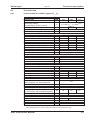
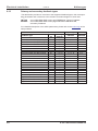
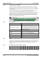
6.2
Technical data
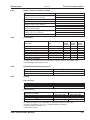
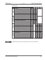
6.2.1
Technical data for 110/230 V (types S3_ _6_)
Electrical data
Order Code
DIM
—
Rated supply voltage
(grounded supply, phase to phase)
V~
Rated input power for S1 operation
kVA
Permitted switch on/off frequency
1/h
Max. DC bus link voltage
V=
Rated output current (rms value, ± 3%)
at 1x115V (observe p. 58)
Arms
at 1x230V (observe p. 58)
Arms
at 3x115V
Arms
at 3x230V
Arms
Peak output current (current for approx. 5s, ± 3%)
at 1x115V (observe p. 58)
Arms
at 1x230V (observe p. 58)
Arms
at 3x115V
Arms
at 3x230V
Arms
Switching frequency of the output stage
kHz
at reduced current (50%)
kHz
Voltage rise speed dU/dt (see hints on page 60!)
at 1x115V
kV/µs
at 1x230V
kV/µs
at 3x115V
kV/µs
at 3x230V
kV/µs
Technical data for brake circuit
—
Threshold for overvoltage switch-off
at 115V
VDC
at 230V
VDC
Motor inductance min.
at 1x115V
mH
at 1x230V
mH
at 3x115V
mH
at 3x230V
mH
Motor inductance max.
mH
Form factor of the output current
—
(rated conditions, min. load inductance)
Bandwidth of current controller
kHz
Residual voltage drop at rated current
V
Thermal dissipation, output stage disabled
W
Thermal dissipation at rated current
W
(incl. PSU losses, without brake dissipation)
Noise emission max.
dB(A)
Mechanical data
Weight
kg
Height, without connectors
mm
Width
mm
Depth, without connectors
mm
Depth, with connectors
mm
*
SERVOSTAR
303
306
310
S30361
S30661
S31061
1 x 110V-10% … 1 x 230V+10%
3 x 110V-10% … 3 x 230V+10%
50/60 Hz
1.1
2.4
4
30
450
3,5*
3*
3.5
3
8*
6*
8
6
10*
10*
10
10
9*
9*
9
9
15*
15*
15
15
8
16 (in process)
20*
20*
20
20
3,0
3,3
3,0
3,3
ð p.28
235
455
3.7
3.7
3.7
4.3
4.3
4.3
2.1
1.3
1.0
4.3
2.6
1.9
Consult our customer support
1.01
> 1.2
4
12
35
60
25
270
90
45
approx. 2.6
279
70
171
< 200
in single-phase applications nom./peak current is limited to value below nominal
value dependent on the motor constant Kt and the motor speed (see p.58).
S300 Instructions Manual
23
Technical description
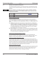
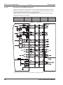
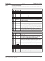
6.2.2
Technical data for 400/480 V (types S3_ _0_)
Electrical data
DIM
Order Code
—
Rated supply voltage
V~
(grounded supply, phase to phase)
Rated input power for S1 operation
kVA
Permitted switch on/off frequency
1/h
Max. DC bus link voltage
V=
Rated output current (rms value, ± 3%)
at 3x208V
Arms
at 3x230V
Arms
at 3x400V
Arms
at 3x480V
Arms
Peak output current (max. approx. 5s, ± 3%)
at 3x208V
Arms
at 3x230V
Arms
at 3x400V
Arms
at 3x480V
Arms
Switching frequency of the output stage
kHz
at reduced current (50%)
kHz
Voltage rise speed dU/dt (see hints on page 60!)
at 3x208V
kV/µs
at 3x230V
kV/µs
at 3x400V
kV/µs
at 3x480V
kV/µs
Technical data for brake circuit
—
Threshold for overvoltage switch-off
a 230V
VDC
a 400V
VDC
a 480V
VDC
Motor inductance min.
at 3x208V
mH
at 3x230V
mH
at 3x400V
mH
at 3x480V
mH
Motor inductance max.
mH
Form factor of the output current
—
(rated conditions, min. load inductance)
Bandwidth of subordinate current controller
kHz
Residual voltage drop at rated current
V
Thermal dissipation, output stage disabled
W
Thermal dissipation at rated current
W
(incl. PSU losses, without brake dissipation)
Noise emission max.
dB(A)
Mechanical data
Weight
kg
Height, without connectors
mm
Width
mm
Depth, without connectors
mm
Depth, with connectors
mm
24
Kollmorgen
09/2011
SERVOSTAR
341
343
346
S30101
S30301
S30601
3 x 208V-10% … 480V+10%, 50/60
Hz
1.2
2.5
5
30
900
2
2
1.5
1.5
5
5
4
3
6
6
6
6
4.5
4.5
4.5
4.5
7.5
7.5
7.5
7.5
8
16 (in process)
12
12
12
12
3,0
3,3
5,7
6,9
ð p.28
455
800
900
7.7
4.6
2.9
8.5
5.1
3.2
14.8
8.9
5.6
17.8
10.7
6.7
Consult our customer support
1.01
> 1.2
5
12
40
25
270
60
90
45
approx. 2.7
279
70
171
< 230
S300 Instructions Manual
Kollmorgen
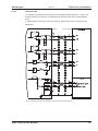
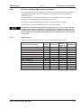
6.2.3
09/2011
Inputs / outputs, Auxiliary voltage
Interface
Analog inputs 1, 2 (resolution 14/12 bit)
Max. common-mode voltage
Digital control inputs
Digital control outputs, active high
BTB/RTO output, relay contacts
Auxiliary supply voltage, electrically isolated,
without motor brake/fan
Auxiliary supply voltage, electrically
isolated, with motor brake/fan
Min./max. output current to brake
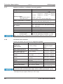
6.2.4
Technical description
electr. data
±10V
±10V
as per IEC 61131-2 Type 1, max. 30VDC
open Emitter, max. 30VDC, 10mA
max. 30VDC, max 42VAC
500mA
20V - 30V
1A
24V (-0% +15%)
2.5A (check voltage drop !)
0.15A / 1.5A
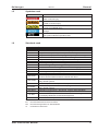
Connectors
Connector
Type
max.
permit- permitcross ted cur- ted tensection*1 rent*2
sion*3
1,5mm²
4A
160V
2,5mm²
12A
630V
4mm²
16A
1000V
0,5mm²
1A
<100V
0,5mm²
1A
<100V
0,5mm²
1A
<100V
0,5mm²
1A
<100V
Control signals X3, X4
Combicon connector
S303-310 Power signals X0,X8,X9 Combicon connector
S341-346 Power signals X0,X8,X9 Combicon connector
Resolver input X2
SubD 9-pin (socket)
Encoder input X1
SubD 15-pin (socket)
PC interface, CAN X6
SubD 9-pin (plug)
Encoder emulation, ROD/SSI X5 SubD 9-pin (plug)
*1 single-line connection
*2 single-line connection with recommended conductor cross section (chapt. 6.2.8)
*3 rated voltage with pollution level 2
6.2.5
Recommended tightening torques
Connector
X0, X8, X9
Grounding bolt
6.2.6
Tightening torque
0.5..0.6 Nm
3.5 Nm
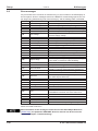
Fusing
Internal fusing
Circuit
Auxiliary voltage 24V
Brake resistor
Internal fuse
3.15 AT
electronic
External fusing
Wire fuses or similar
AC supply feed FN1/2/3 (X0/1; 2; 3)
24V feed
FH1/2
Brake resistor FB1/2 (X8/2; 4)
SERVOSTAR
SERVOSTAR
303*, 341*, 343*
306*, 310*, 346*
6 AT
10 AT
max. 8 AF
6 AT**
6 AT**
EU fuses: types gRL or gL, 400V/500V, T means time-delay, F means fast
US fuses: class RK5 or CC or J or T, 600VAC 200kA, time-delay
* order code reference see p. 20
** Bussmann FWP-xx
S300 Instructions Manual
25
Technical description
6.2.7
Kollmorgen
09/2011
Ambient conditions, ventilation, mounting position
Storage hints
Transport hints
Supply voltage
ð p.17
ð p.17
303-310*:
341-346*:
1x110V-10% …1x230V+10%, 50/60 Hz
3x110V-10% …3x230V+10%, 50/60 Hz
3x208V-10% ...3x 480V+10%, 50/60 Hz
Auxiliary voltage
without brake and fan
with brake or fan
20 V DC ... 30 V DC
24 V DC (-0% +15%), check voltage drop !
0...+40°C under rated conditions
Ambient temperature in operation
+40...+55°C with power derating 2.5% / °C
rel. humidity 85%, no condensation
Humidity in operation
up to 1000 meters a.m.s.l. without restriction
1000…2500 meters a.m.s.l. with power derating
Site altitude
1.5% / 100meters
Pollution level 2 as per IEC 60664-1
Pollution level
Class 3M2 according to IEC 60721-3-3
Vibrations
IP 20 according to IEC 60529
Enclosure protection
vertical ð p.44
Mounting position
Ventilation 1 A and 3 A types
natural convection
all other types
built-on fan (optionally controlled, ð p.126)
Make sure that there is sufficient forced ventilation within the control cabinet.
* order code reference see p. 20
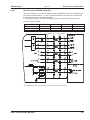
6.2.8
Conductor cross-sections
Following IEC 60204, we recommend for single-axis systems:
1.5 mm² (14awg)
600V,80°C
AC connection
1000V, 80°C,
DC bus link
1.5 mm² (14awg)
shielded for lengths
Brake resistor
>20cm
600V, 80°C, shielded,
1 - 1.5 mm² (14awg)
Motor cables up to 25 m
capacitance <150pF/m
600V,80°C, shielded,
Motor cables 25m to 50 m,
1 mm² (14awg)
capacitance <150pF/m
with motor choke 3YL
4x2x0.25 mm² (22awg),
twisted pairs, shielded,
Resolver, motor thermal
max. 100m
capacitance <120pF/m
control
7x2x0.25 mm² (22awg),
Encoder, motor thermal
twisted pairs, shielded
max.50m
control
8x2x0.25 mm² (22awg),
ComCoder, motor thermal
twisted pairs, shielded
max.25m
control
0.25 mm² (22awg), max 30m
twisted pairs, shielded
Setpoints, AGND
Control signals, BTB, DGND 0.5 mm² (20awg), max 30m
600V, 80°C, shielded,
min. 0.75 mm² (18awg)
Holding brake (motor)
check voltage drop
max. 2.5 mm² (12awg)
check voltage drop
+24 V / DGND
For multi-axis systems, observe the specific operating conditions for your system.
To reach the max. permitted cable length, observe cable requirements ð p. 51.
* Kollmorgen North America supplies cables up to 39 meters
* Kollmorgen Europe supplies cables up to max. length
26
S300 Instructions Manual
Kollmorgen
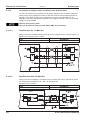
6.3
09/2011
Technical description
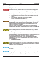
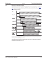
Motor holding brake
A 24V / max.1.5A holding brake in the motor can be controlled directly by the amplifier.
This function does not ensure personnel safety! Hanging load (vertical axes)
require an additional mechanical brake which must be safely operated.
The brake only works with sufficient voltage level (ð p.25). Check voltage drop,
measure the voltage at brake input and check brake function (brake and no brake).
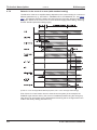
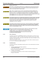
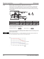
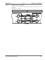
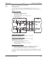
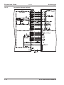
The brake function must be enabled through the BRAKE setting (screen page: Motor). In
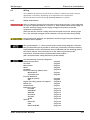
the diagram below you can see the timing and functional relationships between the
ENABLE signal, speed setpoint, speed and braking force. All values can be adjusted with
parameters, the values in the diagram are default values.
During the internal ENABLE delay time of 100ms (DECDIS), the speed setpoint of the
servo amplifier is internally driven down an adjustable ramp to 0V. The output for the
brake is switched on when the speed has reached 5 rpm (VELO), at the latest after 5 seconds (EMRGTO).
The rise (fbrH) and fall (fbrL) times of the holding brake that is built into the motor are different for the various types of motor (see motor manual).
A description of the interface can be found on page 60.
S300 Instructions Manual
27
Technical description
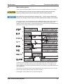
6.4
Kollmorgen
09/2011
LED display
A 3-character LED display indicates the status of the amplifier after switching on the 24V
supply (ð p.107). When the keys on the front panel are used, the parameter and function
numbers are shown, as well as the numbers for any errors that may occur (ð p.108).
6.5
Grounding system
AGND — analog inputs, internal analog ground, encoder emulation, RS232, CAN
DGND — digital inputs/outputs and the 24V supply, optically isolated.
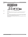
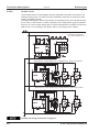
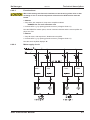
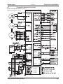
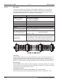
6.6
Dynamic braking (brake circuit)
During dynamic braking with the aid of the motor, energy is fed back into the servo amplifier. This regenerative energy is dissipated as heat in the brake resistor. The brake resistor is switched in by the brake circuit.
The setup software can be used to adapt the brake circuit (thresholds) according to the
electrical supply voltage.
Our customer service can help you with the calculation of the brake power that is necessary for your system. A simple method is described in the "Product Wiki" which is accessible at www.wiki-kollmorgen.eu.
A description of the interface can be found on page 59.
Functional description:
1.- Individual amplifiers, not coupled through the DC bus link circuit (DC+, DC-)
When the energy fed back from the motor has an average or peak power that exceeds
the preset level for the brake power rating, then the servo amplifier generates the warning
“n02 brake power exceeded” and the brake circuit is switched off.
The next internal check of the DC bus link voltage (after a few milliseconds) detects an
overvoltage and the output stage is switched off, with the error message “Overvoltage
F02” (ð p.108).
The BTB/RTO contact (terminals X3/2,3) will be opened at the same time (ðp.89)
2.- Several servo amplifiers coupled through the DC bus link (DC+, DC-)
Using the built-in brake circuit, several amplifiers (even with different current ratings) can
be operated off a common DC bus link, without requiring any additional measures.
The combined (peak and continuous) power of all amplifiers is always available. The
switch-off on overvoltage takes place as described under 1. (above) for the amplifier that
has the lowest switch-off threshold (resulting from tolerances).
Technical data of the brake circuits dependent on the amplifiers type and the mains voltage situation see table on the next page.
28
S300 Instructions Manual
Kollmorgen
09/2011
Technical description
Technical Data:
343 / 346
(S30301/S30601)
341
(S30101)
306 / 310
(S30661/S31061)
303
(S30361)
Brake circuit
Type Rated data
Switch-on (upper) threshold of brake circuit
Overvoltage F02
Internal brake resistor (RBint)
Continuous power for internal resistor (RBint)
Max. brake power (average for 1s)
Pulse brake power
External brake resistor (RBext), optional
Continuous power for external resistor (RBext)
Switch-on (upper) threshold of brake circuit
Overvoltage F02
Internal brake resistor (RBint)
Continuous power for internal resistor (RBint)
Max. brake power (average for 1s)
Pulse brake power
External brake resistor (RBext), optional
Continuous power for external resistor (RBext)
Switch-on (upper) threshold of brake circuit
Overvoltage F02
Internal brake resistor (RBint)
Continuous power for internal resistor (RBint)
Max. brake power (average for 1s)
Pulse brake power
External brake resistor (RBext), optional
Continuous power for external resistor (RBext)
Switch-on (upper) threshold of brake circuit
Overvoltage F02
Internal brake resistor (RBint)
Continuous power for internal resistor (RBint)
Max. brake power (average for 1s)
Pulse brake power
External brake resistor (RBext), optional
Continuous power for external resistor (RBext)
Supply voltage / V
115 230 400 480
200 400
235 455
66
66
20
20
—
0,4 0,35
0,84
3
66
66
0,3
0,3
200 400
235 455
66
66
50
50
—
0,84 0,88
0,84
3
66
66
1
1
400 720 840
455 800 900
91
91
91
20
20
20
—
0,35 0,33 0,34
kW
2,1
7
9
Ohm
91
91
91
kW
0,3
0,3
0,3
V
400 720 840
V
455 800 900
Ohm
91
91
91
W
50
50
50
—
0,91 0,86 0,85
kW
2,1
7
9
Ohm
91
91
91
kW
1,0
1,0
1,0
DIM
V
V
Ohm
W
kW
kW
Ohm
kW
V
V
Ohm
W
kW
kW
Ohm
kW
V
V
Ohm
W
Suitable external brake resistors can be found in our accessories manual.
S300 Instructions Manual
29
Technical description
6.7
09/2011
Kollmorgen
Switch-on and switch-off behavior
This chapter describes the switch-on and switch-off behavior of the S300 and the steps
required to achieve operational stopping or emergency stop behavior that complies with
standards.
The servo amplifier’s 24 V supply must remain constant. The ASCII commands
ACTFAULT (error response) and STOPMODE (ENABLE signal response) dictate
how the drive will behave.
ACTFAULT /
STOPMODE
0
1 (default)
Behavior (see also ASCII reference in the online help of the setup software)
Motor coasts to a standstill in an uncontrolled manner
Motor is braked in a controlled manner
Behavior during a power failure
The servo amplifiers use an integrated circuit to detect if one or more input phases
(power supply feed) fail. The behavior of the servo amplifier is set using the setup software: Under “Response to Loss of Input Phase” (PMODE) on the Basic Setup screen,
select:
l
Warning if the higher-level control system is to bring the drive to a standstill: Warning n05 is output if an input phase is missing, and the motor current is limited to 4 A.
The servo amplifier is not disabled. The higher-level control system can now selectively end the current cycle or start bringing the drive to a standstill. Therefore, the error message “MAINS BTB, F16" is output on a digital output of the servo amplifier
and evaluated by the control system, for instance.
l
Error message if the servo amplifier is to bring the drive to a standstill: Error message F19 is output if an input phase is missing. The servo amplifier is disabled and the
BTB contact opens. Where the factory setting is unchanged (ACTFAULT=1), the motor is braked using the set “EMERGENCY STOP RAMP”.
Behavior when undervoltage threshold is reached
If the undervoltage threshold is undershot in the DC bus link (the threshold value
depends on the type of servo amplifier), the error message “UNDERVOLTAGE, F05" is
displayed. The drive response depends on the ACTFAULT/STOPMODE setting.
Behavior with enabled “holding brake” function
Servo amplifiers with an enabled holding brake function have a special procedure for
switching off the output stage ( ð p. 27). Removing the ENABLE signal triggers electrical
braking. As with all electronic circuits, the general rule applies that there is a possibility of
the internal “holding brake” module failing. Bringing a motor to a standstill using a holding
brake in a way that is personnel safe also requires an electromechanical “make” contact
for the holding equipment and a suppressor device for the brake.
Behavior of the safety function STO
With the personnel safe, certified safety function STO, the drive can be secured on standstill using its internal electronics so that even when power is being supplied, the drive
shaft is protected against unintentional restart. The chapter “Safety Function STO”
describes how to use the STO function. See page 35 onwards.
30
S300 Instructions Manual
Kollmorgen
6.7.1
09/2011
Technical description
Behavior in standard operation
The behavior of the servo amplifier always depends on the current setting of a number of
different parameters (e.g., ACTFAULT, VBUSMIN, VELO, STOPMODE, etc.; see online
help). The diagram below illustrates the correct functional sequence for switching the
servo amplifier on and off.
Devices which are equipped with a selected “Brake” function use a special sequence for
switching off the output stage (ð p.27).
The safety function STO can be used to switch off the drive, so that personnel safety is
ensured at the drive shaft (ð p. 35).
S300 Instructions Manual
31
Technical description
6.7.2
Kollmorgen
09/2011
Behavior in the event of an error (with standard setting)
The behavior of the servo amplifier always depends on the current setting of a number of
different parameters (e.g., ACTFAULT, VBUSMIN, VELO, STOPMODE, etc.; see online
help). The diagram shows the startup procedure and the procedure that the internal control system follows in the event of one or more electrical supply phases failing, assuming
that the standard parameter settings apply.
(F16/F19 = error messages Mains BTB /input phase, F05 = error message Undervoltage)
Even if there is no intervention from an external control system (in the example, the
ENABLE signal remains active), the motor is immediately braked using the emergency
stop ramp if an input phase error is detected and assuming that no changes have been
made to the factory setting (ACTFAULT=1).
32
S300 Instructions Manual
Kollmorgen
6.8
09/2011
Technical description
Stop- / Emergency Stop- Function to IEC 60204
With the personnel safe, certified safety function STO (see page 35 onwards) the
drive can be secured on standstill (torque-free) using its internal electronics so
that even when power is being supplied, the drive shaft is protected against
unintentional restart.
The parameters “STOPMODE” and “ACTFAULT” must be set to 1 in order to
implement the stop categories. If necessary, change the parameters via the
terminal screen of the setup software and store the data in the EEPROM.
Examples for implementation can be found in the Product WIKI on page "Stop and
Emergency Stop Function".
6.8.1
Stop: Standards
The Stop function is used to shut down the machine in normal operation. The Stop functions are defined by IEC 60204.
Category 0:
Shut-down by immediate switching-off of the energy supply to the
drive machinery (i.e. an uncontrolled shut-down);
Category 1:
A controlled shut-down , whereby the energy supply to the drive
machinery is maintained to perform the shut-down, and the energy
supply is only interrupted when the shut-down has been completed;
Category 2:
A controlled shut-down, whereby the energy supply to the drive
machinery is maintained.
The Stop Category must be determined by a risk evaluation of the machine. In addition,
suitable means must be provided to guarantee a reliable shut-down.
Category 0 and Category 1 Stops must be operable independently of the operating mode,
whereby a Category 0 Stop must have priority. Stop functions must be implemented by
disconnection of the appropriate circuitry, and have priority over assigned start functions.
If necessary, provision must be made for the connection of protective devices and
lock-outs. If applicable, the Stop function must signal its status to the control logic. A reset
of the Stop function must not create a hazardous situation.
Examples for implementation can be found in the Product WIKI on page "Stop and
Emergency Stop Function".
S300 Instructions Manual
33
Technical description
6.8.2
09/2011
Kollmorgen
Emergency Stop: Standards
The emergency Stop function is used for the fastest possible shut-down of the machine
in a dangerous situation. The Emergency Stop function can be triggered by the actions of
a single person. It must be fully functional and available at all times. The user must not
have to work out how to operate this mechanism.
The Emergency Stop function is defined by IEC 60204.
In addition to the requirements for Stop, the emergency Stop must fulfil the following
requirements:
l
emergency stop must have priority over all other functions and controls in all operating situations;
l
the energy supply to any drive machinery that could cause dangerous situations
must be switched off as fast as possible, without causing any further hazards (e.g. by
using mechanical latching devices that do not require an external supply of energy,
by counter-current braking in Stop Category 1);
l the reset must not initiate a restart.
If necessary, provision must be made for the additional connection of emergency stop
devices (see IEC 60204, "Requirements for emergency stop devices"). The Emergency
Stop must be effective as a stop of either Category 0 or Category 1.
The Emergency Stop Category must be determined by a risk evaluation of the machine.
Category 0
Only hard-wired, electromechanical components may be used for the Category 0 Emergency Stop function. It must not be triggered using switching logic (hardware or software),
by transferring commands via a communication network, or via a data link.
The drive must be shut down using an electromechanical circuit. If the connected servo
motor has an integrated brake, this must always be controlled by an electromechanical
circuit as well.
Category 1
With the Category 1 Emergency Stop function, there must be absolute certainty in terms
of the power supply for the machine drives being switched off (i.e., secured) using electromechanical components. Additional Emergency Stop equipment may be connected.
Bringing the motor to a standstill by interrupting the mains supply and using controlled
electronic braking. The 24 V supply for the servo amplifier must remain constant. The
issue of which circuit should be used is highly dependent on the requirements of the
application at hand.
In most servo motors a brake has only the function of a holding brake. To ensure an
emergency stop function, the braking torque that is required must be checked. If the holding brake fulfills the dynamic requirements, it must be taken into acount that this application will cause increased wear.
Examples for implementation can be found in the Product WIKI on page "Stop and
Emergency Stop Function".
34
S300 Instructions Manual
Kollmorgen
6.9
Technical description
09/2011
Safety function STO
A frequently required application task is the protection of personnel against the restarting
of drives. The S300 servo amplifier offers, even in the basic version, a single channel
STO function (Safe Torque Off) that can be used as a personnel safe restart lock.
The safety function STO can be operated from a safe external control (semiconductor
output or driven contact).
The safetys concept is certified. The safety circuit concept for realizing the safety function
"Safe Torque Off" in the servo amplifiers S300 is suited for SIL CL 2 according to IEC
62061 and PLd according to ISO 13849-1.
Advantages of the restart lock STO :
—
the DC bus link remains charged up, since the mains supply line remains active
—
only low voltages are switched, so there is no contact wear
—
very little wiring is required
6.9.1
Safety characteristic data
The subsystems (servo amplifiers) are totally described for safety technics with the
characteristic data SIL CL, PFHD and SFF.
Device
Operation mode
STO-Enable STO single channel
S300 Instructions Manual
EN
13849-1
PLd
EN 62061
SIL CL 2
PFHD
[1/h]
0
SFF
[%]
100
MTTFd
[Year]
311
35
Technical description
6.9.2
09/2011
Kollmorgen
Safety instructions
Drives with a suspended load must have an additional safe mechanical blocking
(e.g. by a motor-holding brake). The amplifier cannot hold the load when STO is
active. That could result in serious injury.
When STO is engaged during operation by separating input STO-Enable from
24VDC, the motor runs down out of control and the servo amplifier displays the
error F27. There is no possibility of braking the drive controlled. If a controlled
braking before the use of STO is necessary, the drive must be braked and the input
STO-ENABLE has to be separated from +24 VDC time-delayed.
If the safety function STO is automatically activated by a control system, then make
sure that the output of the control is monitored for possible malfunction. This can
be used to prevent a faulty output from unintentionally activating the safety
function STO. Since the restart lock is a single-channel system, erroneous
engaging will not be recognized.
The safety function STO does not provide an electrical separation from the power
output. If access to the motor power terminals is necessary, the servo amplifier
must be disconnected from mains supply considering the discharging time of the
DC bus link (intermediate circuit).
Keep to the following functional sequence when the restart lock STO is used :
1. Brake the drive in a controlled manner (speed setpoint = 0V)
2. When speed = 0 rpm, disable the servo amplifier (enable = 0V)
3. If there is a suspended load, block the drive mechanically
4. Activate the restart lock STO
6.9.3
Use as directed
The safety function STO is exclusively intended to provide safety for personnel, by preventing the restart of a system. To achieve this personnel safety, the wiring of the safety
circuits must meet the safety requirements of IEC 60204, ISO 12100, IEC 62061 SIL CL2
respectively ISO 13849-1 PLd.
If STO is automatically activated by a control system, then make sure that the output of
the control is monitored for possible malfunction.
6.9.4
Prohibited Use
The safety function STO must not be used if the drive is to be made inactive for the following reasons:
1. - cleaning, maintenance and repair operations
- long inoperative periods
In such cases, the entire system should be disconnected from the supply by the
personnel, and secured (main switch).
2. - emergency-stop situations
In an emergency-stop situation, the main contactor is switched off (by the
emergency-stop button).
36
S300 Instructions Manual
Kollmorgen
6.9.5
09/2011
Technical data and pinning
Input voltage
Input current
Peak current
6.9.6
Technical description
20 V..30 V
33 mA – 40 mA (Ieff)
100 mA (Is)
Enlosure
Since the servo amplifier meets enclosure IP20, you must select the environment ensuring a safe operation of the servo amplifier. The enclosure must meet IP54 at least.
6.9.7
Wiring
When using STO wiring leads outside the control cabinet, the cables must be laid durably
(firmly), protected from outside damage (e.g. laying in a cable duct), in different sheathed
cables or protected individually by grounding connection.
Wiring remaining within the demanded enclosure must meet the requirements of the standard IEC 60204-1.
S300 Instructions Manual
37
Technical description
6.9.8
Kollmorgen
09/2011
Functional description
In case of use of the STO function the input STO-Enable must be connected to the exit of
a security control or a safety relay, which meets at least to therequirements of the SIL
CL2 according to IEC 62061 and PL d according to ISO 13849-1 (see the connection diagram on page 40).
Possible states of the servo amplifier in connection with STO function:
STO-ENABLE ENABLE
Display
Motor has torque SIL CL2 / PL d
0V
0V
-Sno
yes
0V
+24 V
F27
no
yes
+24 V
0V
normal status e.g. 06
no
no
+24 V
+24 V
normal status e.g. E06
yes
no
When STO function is engaged during operation by separating input STO-Enable
from 24 VDC, the motor runs down out of control and the servo amplifier displays
the error F27. There is no possibility of braking the drive controlled. If a controlled
braking before the use of the restart lock is necessary, the drive must be braked
and the input STO-ENABLE has to be separated from +24 VDC time-delayed.
Because restart lock is a single-channel system, erroneous engaging will not be
recognized. Therefore the output of the control must be supervised for possible
malfunction.
If the STO function is not needed in the application, then the input STO-ENABLE
must be connected directly with +24VDC. The STO function is passed by now and
cannot be used. The servo amplifier cannot be used as a safety component
referring to the EC Machine Directive now.
When wiring the input STO-ENABLE within one enclosure it must be paid attention to the
fact that the used cables and the enclosure meet the requirements of IEC 60204-1.
If the wiring leads outside the demanded enclosure, the cables must be laid durably
(firmly), and protected from outside damage (see chapter "Wiring").
38
S300 Instructions Manual
Kollmorgen
6.9.8.1
09/2011
Technical description
Signal diagram (sequence)
The diagram shows how to use STO function to ensure a safe stop of the drive and error
free operation of the servo amplifier.
1.
2.
3.
Brake the drive in a controlled manner (speed setpoint = 0 V)
When speed = 0 rpm, disable the servo amplifier (Enable = 0 V)
Activate the STO function (STO-Enable = 0 V)
Suspended loads can set themselves to motion on motors without brake, because
the motor loses all torque when STO is engaged (STO-Enable open and/or 0 V). Use
motors with built-in holding brake.
S300 Instructions Manual
39
Technical description
6.9.8.2
09/2011
Kollmorgen
Control circuit
The example shows a circuit diagram with two separated work areas connected to one
emergency stop circuit. For each work area individually "safe stop" of the drives is switched by a protective screen.
The safety switch gears used in the example are manufactured by Pilz and fulfill at least
the PL d acc. to ISO 13849-1. Further information to the safety switch gears is available
from Pilz. The use of safety switch gears of other manufacturers is possible, if these also
fulfill the SIL CL 2 according to IEC 62061 and PL d according to ISO 13849-1.
Emergency-stop circuit
acc. to ISO 13849-1 PL e
Safe stop acc. to ISO 13849-1 PL d, single channel, group 1 for 2 drives
Safe stop acc. to ISO 13849-1 PL d, single channel, group 2 for 2 drives
Consider the wiring instructions on page 37.
40
S300 Instructions Manual
Kollmorgen
6.9.8.3
09/2011
Technical description
Functional test
With initial starting and after each interference into the wiring of the drive or after
exchange of one or several components of the drive the STO function must be
tested.
1. Method:
1. Stop drive, with setpoint 0V, keep servo amplifier enabled.
DANGER: Do not enter hazardous area!
2. Activate STO e.g. by opening protective screen. (voltage at X4/5 0 V)
Now the BTB/RTO contact opens, the net contactor releases and the servoamplifier displays error F27.
2. Method:
1. Stop all drives, with setpoint 0V, disable servo amplifier.
2. Activate STO e.g. by opening protective screen. (voltage at X4/5 0 V)
Now the servo amplifier displays -S-.
6.9.8.4
Mains supply circuit
S300
S300 Instructions Manual
S300
S300
S300
41
Technical description
Kollmorgen
09/2011
6.10
Shock-hazard protection
6.10.1
Leakage current
Leakage current via the PE conductor results from the combination of equipment and
cable leakage currents. The leakage current frequency pattern comprises a number of
frequencies, whereby the residual-current circuit breakers definitively evaluate the 50Hz
current. As a rule of thumb, the following assumption can be made for leakage current on
our low-capacity cables at a mains voltage of 400 V, depending on the clock frequency of
the output stage:
Ileak = n x 20mA + L x 1mA/m at 8kHz clock frequency at the output stage
Ileak = n x 20mA + L x 2mA/m at a 16kHz clock frequency at the output stage
(where Ileak=leakage current, n=number of amplifiers, L=length of motor cable)
At other mains voltage ratings, the leakage current varies in proportion to the voltage.
Example:
2 x servo amplifiers + a 25m motor cable at a clock frequency of 8kHz:
2 x 20mA + 25m x 1mA/m = 65mA leakage current.
Since the leakage current to PE is more than 3.5 mA, in compliance with
IEC 61800-5-1 the PE connection must either be doubled or a connecting cable with
a cross-section >10mm² must be used. Use the PE terminals and the PE bolt in
order to fulfil this requirement.
The following measures can be used to minimise leakage currents.
— Reduce the length of the engine cable
— Use low-capacity cables (see p.51)
— Remove external EMC filters (radio-interference suppressors are integrated)
6.10.2
Residual current protective device (RCD)
In conformity with IEC 60364-4-41 – Regulations for installation and IEC 60204 – Electrical equipment of machinery, residual current protective devices (called RCD below) can
be used provided the requisite regulations are complied with. The S300 is a 3-phase system with a B6 bridge. Therefore, RCDs which are sensitive to all currents must be
used in order to detect any D.C. fault current.
Rated residual currents in the RCD
Protection against "indirect contact" for stationary and mobile equipment,
as well as for "direct contact".
50 -300 mA Protection against "indirect contact" for stationary equipment
10 -30 mA
Recommendation: In order to protect against direct contact (with motor cables
shorter than 5 m) we recommend that each servo amplifier be protected
individually using a 30mA RCD which is sensitive to all currents.
If you use a selective RCD, the more intelligent evaluation process will prevent spurious
tripping of the RCD.
6.10.3
Isolating transformers
When protection against indirect contact is absolutely essential despite a higher leakage
current, or when an alternative form of shock-hazard protection is sought, the S300 can
also be operated via an isolating transformer (schematic connection see p.56). A
ground-leakage monitor can be used to monitor for short circuits.
Be advised to keep the length of wiring between the transformer and the servo
amplifier as short as possible.
42
S300 Instructions Manual
Kollmorgen
09/2011
7
Mechanical Installation
7.1
Safety Instructions
Mechanical Installation
There is a danger of electrical shock by high EMC level which could result in injury,
if the servo amplifier (or the motor) isn't properly EMC-grounded. Do not use
painted (i.e. non-conductive) mounting plates.
Protect the servo amplifier from impermissible stresses. In particular, do not let
any components become bent or any insulation distances altered during transport
and handling. Avoid contact with electronic components and contacts.
The servo amplifier will switch-off itself in case of overheating. Ensure that there is
an adequate flow of cool, filtered air into the bottom of the control cabinet, or use a
heat exchanger. Please refer to page 26.
Don't mount devices, which produce magnetic fields, directly beside the servo
amplifier. Strong magnetic fields could directly affect internal components. Install
devices which produce magnetic field with distance to the servo amplifiers and/or
shield the magnetic fields.
7.2
Guide to mechanical installation
The following notes should help you to carry out the mechanical installation.
Site
In a closed control cabinet. Please refer to page 26.
The site must be free from conductive or corrosive materials.
For the mounting position in the cabinet ð p.44.
Ventilation
Check that the ventilation of the servo amplifier is unimpeded, and
keep within the permitted ambient temperature ð p.26. Keep the required space clear above and below the servo amplifier ð p.44.
Assembly
Assemble the servo amplifier and power supply close together, on the
conductive, grounded mounting plate in the cabinet.
Grounding
Shielding
For EMC-compliant shielding and grounding ð p.55.
Ground the mounting plate, motor housing and CNC-GND of the
control system. Notes on connection techniques ð p.50.
S300 Instructions Manual
43
Mechanical Installation
7.3
09/2011
Kollmorgen
Assembly
Material: 3 x M5 hexagon socket screws to ISO 4762
Tool required : 4 mm Allen key
S300
44
S300 Instructions Manual
Kollmorgen
7.4
09/2011
Mechanical Installation
Dimensions
1
xx6
S3 x01
x
S3
0
.31
3..
6
0
3
.34
1..
AR
4
T
3
OS
R
TA
RV
S
E
S
O
RV
SE
S300 Instructions Manual
45
Mechanical Installation
Kollmorgen
09/2011
This page has been deliberately left blank.
46
S300 Instructions Manual
Kollmorgen
09/2011
8
Electrical installation
8.1
Safety Instructions
Electrical installation
Never undo any electrical connections to the servo amplifier while it is live. There
is a danger of electrical arcing with damage to contacts and serious personal
injury. Wait at least five minutes after disconnecting the servo amplifier from the
main supply power before touching potentially live sections of the equipment (e.g.
contacts) or undoing any connections.
Capacitors can still have dangerous voltages present up to five minutes after
switching off the supply power. To be sure, measure the voltage in the DC Bus link
and wait until it has fallen below 40V.
Control and power connections can still be live, even if the motor is not rotating.
Wrong mains voltage, unsuitable motor or wrong wiring will damage the amplifier.
Check the combination of servo amplifier and motor. Compare the rated voltage
and current of the units. Implement the wiring according to the connection diagram
on page 49.
Make sure that the maximum permissible rated voltage at the terminals L1, L2, L3
or +DC, –DC is not exceeded by more than 10% even in the most unfavorable
circumstances (see IEC 60204-1).
Excessively high external fusing will endanger cables and devices. The fusing of
the AC supply input and 24V supply must be installed by the user, best values are
given on p.25. Hints for use of Residual-current circuit breakers (FI) ð p.42.
Correct wiring is the basis for reliable functioning of the servo system.
Route power and control cables separately. We recommend a distance of at least
200mm. This improves the interference immunity. If a motor power cable is used
that includes cores for brake control, the brake control cores must be separately
shielded. Ground the shielding at both ends. Ground all shielding with large areas
(low impedance), with metalized connector housings or shield connection clamps
wherever possible. Notes on connection techniques can be found on page 50.
Feedback lines may not be extended, since thereby the shielding would be
interrupted and the signal processing could be disturbed. Lines between amplifiers
and external brake resistor must be shielded. Install all power cables with an
adequate cross-section, as per IEC 60204 (ð p.26) and use the requested cable
material (ð p. 51) to reach max. cable length.
The servo amplifier's status must be monitored by the PLC to acknowledge critical
situations. Wire the BTB/RTO contact in series into the emergency stop circuit of
the installation. The emergency stop circuit must operate the supply contactor.
It is permissible to use the setup software to alter the settings of the servo
amplifier. Any other alterations will invalidate the warranty.
S300 Instructions Manual
47
Electrical installation
8.2
Kollmorgen
09/2011
Guide to electrical installation
The following notes should help you to carry out the electrical installation.
Cable selection Select cables in accordance with IEC 60204 ð p.26.
Grounding
Shielding
Wiring
Final check
48
For EMC-compliant shielding and grounding ð p.55.
Ground the mounting plate, motor housing and CNC-GND of the
control system. Notes on connection techniques ð p.50.
Route power leads and control cables separately.
Wire the BTB/RTO contact in series into the emergency stop
circuit of the system.
— Connect the digital control inputs and outputs.
— Connect up AGND (also if fieldbuses are used).
— Connect the analog input source, if required.
— Connect the feedback device.
— Connect the encoder emulation, if required.
— Connect the expansion card
— (see corresponding notes from page 111).
— Connect the motor cable
— Connect shielding to EMC connectors (shield connection) at both
— ends. Use the motor choke (3YL) if cable > 25 meters.
— Connect motor-holding brake, connect shielding to EMC
— connector/shield connection at both ends.
— If required, connect the external brake resistor (with fusing).
— Connect the auxiliary supply
— (maximum permissible voltage values ð p.26).
— Connect the main electrical supply
— (maximum permissible voltage values ð p.26).
— Connect the PC (ð p.90).
— Final check of the implementation of the wiring against the
— wiring diagrams that have been used.
S300 Instructions Manual
Kollmorgen
8.3
Electrical installation
09/2011
Wiring
The installation procedure is described as an example. A different procedure may be
appropriate or necessary, depending on the application of the equipments.
We provide further know-how through training courses (on request).
8.3.1
Safety instructions
There is a danger of electrical arcing with serious personal injury. Only install and
wire up the equipment when it is not live, i.e. when neither the electrical supply nor
the 24 V auxiliary voltage nor the supply voltages of any other connected
equipment is switched on.
Take care that the cabinet is safely disconnected (with a lock-out, warning signs
etc.). The individual voltages will be switched on for the first time during setup.
Only professional staff who are qualified in electrical engineering are allowed to
install the servo amplifier.
X
, which you will find in all the wiring diagrams, indicates
The ground symbol
that you must take care to provide an electrically conductive connection with the
largest feasible surface area between the unit indicated and the mounting plate in
the control cabinet. This connection is for the effective grounding of HF
interference, and must not be confused with the PE-symbol W
(PE = protective earth, safety measure as per IEC 60204).
Use the following connection diagrams :
Safety Function STO
Overview
Mains power
Motor
Feedback
Electronic Gearing / Master Slave
Master-Slave
Pulse-Direction
Encoder Emulation
ROD (A quad B)
SSI
Digital and analog inputs and outputs
RS232 / PC
CAN Interface
Expansion cards
I/O-14/08
PROFIBUS
SERCOS
DeviceNet
SynqNet
2CAN
Options
EtherCAT
FAN
EtherCAT&FAN
S300 Instructions Manual
: page 40
: page 55
: page 57
: page 60
: page 61ff
: page 81
: page 82
: page 85
: page 86
: page 87ff
: page 90
: page 91
: page 114
: page 115
: page 117
: page 118
: page 122
: page 124
: page 125
: page 126
: page 126
49
Electrical installation
8.3.2
09/2011
Kollmorgen
Shielding connection to the front panel
Remove the outside shroud of the cable
and the shielding braid on the desired core
length. Secure the cores with a cable tie.
Remove the outside shroud of the line on a
length from for instance 30mm without damaging the shielding braid.
Pull a cable tie by the slot in the shielding
rail on the front panel of the servo amplifier.
Press the shielding of the cable firmly
against the front panel with the cable tie.
Use the shield clamp that is delivered with
the motor cable for the shield connection of
the motor cable. The clamp must be hooked in the lower shroud and guarantees optimal contact between shield and shroud.
50
S300 Instructions Manual
Kollmorgen
8.3.3
09/2011
Electrical installation
Technical data for connecting cables
Further information on the chemical, mechanical and electrical characteristics of the
cables can be obtained from our customer service.
Observe the rules in the section "Conductor cross-sections" on page 26. To reach
the max. permitted cable length, you must use cable material that matches the
capacitance requirements listed below.
Capacitance (phase to shield)
Motor cable
less than 150 pF/m
Resolver/Encoder cable less than 120 pF/m
Example: Motor cable
Technical data
For a detailed description of cable types and how to assemble them, please refer to the
accessories manual.
Motor cables longer than 25m require the use of a motor choke 3YL or 3YLN.
S300 Instructions Manual
51
Electrical installation
8.4
Kollmorgen
09/2011
Components of a servo system
PC
Controls / PLC
S300
24V PSU
Fuses
Brake resistor
(optional)
Drive cut-out
Motor choke
(optional)
Terminals
Motor
Cables drawn bold are shielded. Electrical ground is drawn with dash-dotted lines.
Optional devices are connected with dashed lines to the servo amplifier. The
required accessories are described in our accessories manual.
52
S300 Instructions Manual
Kollmorgen
8.5
09/2011
Electrical installation
Block diagram
The block diagram below just provides an overview.
S300 Instructions Manual
53
Electrical installation
8.6
09/2011
Kollmorgen
Connector assignments
The connectors of the expansion
card depend on used expansion
card (see pages 112 ff).
54
S300 Instructions Manual
Kollmorgen
8.7
09/2011
Electrical installation
Connection diagram (Overview)
Refer to the Safety Instructions (ðp.10)
and Use as Directed (ð p.11) !
S300
ð p.64ff
ð p.87
ð p.63
ð p.88
ð p.60
ð p.59
ð p.57
ð p.89
ð p.88
ð p.37
ð p.85
ð p.86
ð p.81
ð p.82
ð p.91
ð p.57
ð p.90
ð p.112
ð p.115
ð p.116
ð p.118
ð p.125
ð p.122
S300 Instructions Manual
55
Electrical installation
Kollmorgen
09/2011
8.8
Electrical supply
8.8.1
Connection to various mains supply networks
There is a danger of electrical shock with serious personal injury if the servo
amplifier isn't properly grounded. An isolating transformer is always required for
400 … 480V networks that are asymmetrically grounded or not grounded.
110V : SERVOSTAR 303-310*
230V : all types
400V / 480V : SERVOSTAR 341-346*
S300
S300
S300
S300
S300
S300
S300
S300
S300
S300
S300
* Order code reference see p. 129
56
S300 Instructions Manual
Kollmorgen
8.8.2
09/2011
Electrical installation
24V auxiliary supply (X4)
— External 24V DC power supply, electrically isolated, e.g. via an isolating transformer
— Required current rating ð p.23
— Integrated EMC filter for the 24V auxiliary supply
S300
8.8.3
Mains supply connection (X0), three phase
—
—
Directly to 3-phase supply network, filter is integrated
Fusing (e.g. fusible cut-outs) to be provided by the user ð p.25
S300
8.8.4
Mains supply connection (X0), two phase without neutral
S300
S300 Instructions Manual
57
Electrical installation
8.8.5
Kollmorgen
09/2011
Mains supply connection (X0), single phase with neutral
S300 with 230V version (SERVOSTAR 303-310) can be operated with a single phase
mains supply. In single phase operation the electrical power of the amplifier is limited.
The table below shows the maximum rated power (Pn) and peak power (Pp) with single
phase operation:
S300
max. electrical power
VBUSBAL0 (115V)
VBUSBAL1 (230V)
SERVOSTAR 303 SERVOSTAR 306 SERVOSTAR 310
Pn / W Pp / W Pn / W Pp / W Pn / W Pp / W
423
704
423
704
423
704
845
2535
1127
2535
1127
2535
The maximum possible current depends on the motor torque constant kT and on the
maximum speed of the connected motor:
Continuous currrent: I rms =
Pn × 60
2 × p × kT × n
peak current: I peak =
Pp × 60
2 × p × kT × n
Speed can be limited with the ASCII parameter VLIM to reach the necessary current
for the required torque.
With a special motor type (kT = constant depending on the motor type) the possible output current depending on speed is similar to the diagram below:
Ipeak
Irms
58
S300 Instructions Manual
Kollmorgen
8.9
09/2011
Electrical installation
External brake resistor (X8)
Remove the plug-in link between the terminals X8/5 (-RB) and X8/4 (+Rbint).
S300
8.10
DC bus link (X8)
Terminals X8/1 (-DC) and X8/3 (+RBext). Can be connected in parallel, whereby the
brake power is divided between all the amplifiers that are connected to the same DC bus
link circuit.
S300
S300
The servo amplifiers can be destroyed, if DC bus link voltages are different. Only
servo amplifiers with mains supply from the same mains (identical mains supply
voltage) may be connected by the DC bus link. Use unshielded single cores
(2.5mm²) with a max. length of 200 mm. Use shielded cables for longer lengths.
S300
S701...724 with
HWR* < 2.00
no
S701...724 with
HWR* ³ 2.00
Ä
S300
Ä
*HWR = Hardware Revision (see nameplate)
SERVOSTAR 303-310
The sum of the rated currents for all of the servo amplifiers connected in parallel
to an SERVOSTAR 303-310 must not exceed 24 A.
SERVOSTAR 341-346
The sum of the rated currents for all of the servo amplifiers connected in parallel
to an SERVOSTAR 341-346 must not exceed 40A.
Information for fusing can be found in the "Product WIKI", check www.wiki-kollmorgen.eu.
S300 Instructions Manual
59
Electrical installation
8.11
09/2011
Kollmorgen
Motor connection with brake (X9)
Together with the motor supply cable and motor winding, the power output of the servo
amplifier forms an oscillating circuit. Characteristics such as cable capacity, cable length,
motor inductance, frequency and voltage rise speed (see Technical Data, p. 23) determine the maximum voltage in the system.
The dynamic voltage rise can lead to a reduction in the motor’s operating life and,
on unsuitable motors, to flashovers in the motor winding.
— Only install motors with insulation class F (acc. to IEC60085) or above
— Only install cables that meet the requirements on p.26 and p.51.
The brake function does not ensure personnel safety! Hanging load (vertical axes)
require an additional mechanical brake which must be safely operated
Cable length £ 25 meters
S300
Cable length >25 meters
With long motor cables leakage currents endanger the output stage of the S300.
For cable lengths above 25m up to max. 50m, a motor choke 3YLor 3YLN (see
accessories manual) must be wired into the motor cable, close to the amplifier.
S300
60
S300 Instructions Manual
Kollmorgen
8.12
Electrical installation
09/2011
Feedback systems
Every closed servo system will normally require at least one feedback device for sending
actual values from the motor to the servo drive. Depending on the type of feedback
device used, information will be fed back to the servo amplifier using digital or analog
means. Up to three feedback devices can be used at the same time. S300 supports the
most common types of feedback device whose functions must be assigned with the parameters
FBTYPE
set on DRIVEGUI.EXE screen page FEEDBACK,
primary Feedback, wiring ð p.61ff
EXTPOS
set on DRIVEGUI.EXE screen page POSITION CONTROLLER,
secondary Feedback, wiring ð p.61ff
GEARMODE
set on DRIVEGUI.EXE screen page ELECTRONIC GEARING,
encoder for electronic gearing, wiring ð p.81
in the setup software. Scaling and other settings must always be made here.
For a detailed description of the ASCII parameters, please refer to the online help of the
setup software.
Some possible configurations:
Motor Feedback
FBTYPE
FBTYPE
FBTYPE
X1
X2
X5
Motor Feedback & External Position Feedback
EXTPOS
X1
X2
FBTYPE
X2
FBTYPE
EXTPOS
X5
X1
FBTYPE
EXTPOS
X5
Motor Feedback & Master Slave
ENCMODE
GEARMODE
X5
X5
FBTYPE
X1
X2
Master
FBTYPE
Slave
Motor Feedback & Master Slave & External Position Feedback
ENCMODE
GEARMODE
X5
X5
X1
EXTPOS
FBTYPE
FBTYPE
X1
X2
Master
S300 Instructions Manual
Slave
61
Electrical installation
8.13
Kollmorgen
09/2011
Primary and secondary feedback types
The table below provides an overview of the supported feedback types, their corresponding parameters and a reference to the relevant connection diagram in each case.
FBTYPE
EXTPOS
set on DRIVEGUI.EXE screen page FEEDBACK, primary Feedback
set on DRIVEGUI.EXE screen page POSITION CONTROLLER,
secondary Feedback
For a detailed description of the ASCII parameters, please refer to the online help of the
setup software.
ConnecFeedback type
tor
Resolver
X2
SinCos Encoder BiSS (B) analog
X1
SinCos Encoder BiSS (B, C) digital
X1
SinCos Encoder ENDAT 2.1
X1
SinCos Encoder ENDAT 2.2
X1
SinCos Encoder HIPERFACE
X1
SinCos Encoder SSI (linear)
X5/X1
SinCos Encoder w/o data channel
X1
SinCos Encoder + Hall
X1
ROD* 5V w/o zero, 1.5MHz
X1
ROD* 5V with zero
X1
ROD* 5V with zero, with Hall
X1
ROD* 5V with zero
X5
ROD* 5V with zero, with Hall
X5/X1
ROD* 24V w/o zero
X3
ROD* 24V w/o zero, with Hall
X3/X1
SSI
X5
Hall
X1
Sensorless (w/o Feedback)
Step/Direction 5V, 1.5 MHz
X1
Step/Direction 5V, 1.5 MHz
X5
Step/Direction 24V, 100 kHz
X3
Wiring
diagram
ð p.63
ð p.64
ð p.65
ð p.66
ð p.67
ð p.68
ð p.69
ð p.70
ð p.71
ð p.72
ð p.73
ð p.74
ð p.75
ð p.76
ð p.77
ð p.78
ð p.79
ð p.80
ð p.82
ð p.83
ð p.82
primary
secondary
FBTYPE
EXTPOS
0
23, 24
20, 22, 33
4, 21
32
2
28
1, 3, 7, 8
5, 6
30, 31
17,27
15
13, 19
18
12, 16
14
9
11
10
-
11, 12
8
9
6, 7
30
10
3
2
5
27
4
1
* ROD is an abbreviation for “incremental encoder”.
62
S300 Instructions Manual
Kollmorgen
8.13.1
09/2011
Electrical installation
Resolver (X2)
Connection of a Resolver (2 to 36-poles) as a feedback system (primary, ð p.62). The
thermal control in the motor is connected via the resolver cable to X2 and evaluated
there.
If cable lengths of more than 100m are planned, please consult our customer service.
FBTYPE: 0
S300
SubD 9
round 12-pin
The pin assignment shown on the encoder side relates to the Kollmorgen motors.
S300 Instructions Manual
63
Electrical installation
8.13.2
Kollmorgen
09/2011
Sine Encoder with BiSS analog (X1)
Wiring of a single-turn or multi-turn sine-cosine encoder with BISS interface as a feedback system (primary and secondary, ð p.62). The thermal control in the motor is connected via the encoder cable to X1 and evaluated there.
If cable lengths of more than 50m are planned, please consult our customer service.
Frequency limit (sin, cos): 350 kHz
Type
5V analog (BiSS B)
12V analog (BiSS B)
FBTYPE
23
24
EXTPOS
SubD 15
GEARMODE
-
Up
5V +/-5%
7,5...11V
round, 17-pin
S300
The pin assignment shown on the encoder side relates to the Kollmorgen motors.
64
S300 Instructions Manual
Kollmorgen
8.13.3
Electrical installation
09/2011
Sine Encoder with BiSS digital (X1)
Wiring of a single-turn or multi-turn digital encoder with BISS interface as a feedback system (primary and secondary, ð p.62). The thermal control in the motor is connected via
the encoder cable to X1 and evaluated there.
If cable lengths of more than 50m are planned, please consult our customer service.
Frequency limit: 1,5 MHz
Type
5V digital (BiSS B)
12V digital (BiSS B)
5V digital (BiSS C)
FBTYPE
20
22
33
EXTPOS
11
11
12
SubD 15
GEARMODE
11
11
12
Up
5V +/-5%
7,5...11V
5V +/-5%
round, 17-pin
S300
The pin assignment shown on the encoder side relates to the Kollmorgen motors.
S300 Instructions Manual
65
Electrical installation
8.13.4
Kollmorgen
09/2011
Sine Encoder with EnDat 2.1 (X1)
Wiring of a single-turn or multi-turn sine-cosine encoder with EnDat 2.1 interface as a
feedback system (primary and secondary, ð p.62). Preferred types are the optical encoder ECN1313 / EQN1325 and the inductive encoder ECI 1118/1319 or EQI 1130/1331.
The thermal control in the motor is connected via the encoder cable to X1 and evaluated
there. All signals are connected using our pre-assembled encoder connection cable. If
cable lengths of more than 50m are planned, please consult our customer service.
Frequency limit (sin, cos): 350 kHz
Type
ENDAT 2.1
ENDAT 2.1 + Wake&Shake
S300
FBTYPE
4
21
SubD 15
EXTPOS
8
8
GEARMODE
8
8
round, 17-pin
The pin assignment shown on the encoder side relates to the Kollmorgen motors.
66
S300 Instructions Manual
Kollmorgen
8.13.5
09/2011
Electrical installation
Sine Encoder with EnDat 2.2 (X1)
Wiring of a single-turn or multi-turn sine-cosine encoder with EnDat 2.2 interface as a
feedback system (primary, ð p.62). The thermal control in the motor is connected via the
encoder cable to X1 and evaluated there. All signals are connected using our
pre-assembled encoder connection cable.
If cable lengths of more than 50m are planned, please consult our customer service.
Frequency limit: 1.5 MHz
Type
ENDAT 2.2
FBTYPE
32
S300
SubD15
EXTPOS
13
GEARMODE
13
round, 17-pin
The pin assignment shown on the encoder side relates to the Kollmorgen motors.
S300 Instructions Manual
67
Electrical installation
8.13.6
Kollmorgen
09/2011
Sine Encoder with HIPERFACE (X1)
Wiring of a single-turn or multi-turn sine-cosine encoder with HIPERFACE interface as a
feedback system (primary and secondary, ð p.62).
The thermal control in the motor is connected via the encoder cable to X1 and evaluated
there. All signals are connected using our pre-assembled encoder connection cable.
If cable lengths of more than 50m are planned, please consult our customer service.
Frequency limit (sin, cos): 350 kHz
Type
HIPERFACE
S300
FBTYPE
2
SubD 15
EXTPOS
9
GEARMODE
9
round, 17-pin
The pin assignment shown on the encoder side relates to the Kollmorgen motors.
68
S300 Instructions Manual
Kollmorgen
8.13.7
09/2011
Electrical installation
Sine Encoder with SSI (X5, X1)
Wiring of sine-cosine encoder with SSI interface as a linear feedback system
(primary, ð p.62) to X5.
The thermal control in the motor is connected via the encoder cable to X1 and evaluated
there. All signals are connected using our pre-assembled encoder connection cable. If
cable lengths of more than 50m are planned, please consult our customer service.
Frequency limit (sin, cos): 350 kHz
Type
SinCos SSI 5V linear
FBTYPE
28
EXTPOS
-
GEARMODE
-
SubD 15
S300
S300 Instructions Manual
69
Electrical installation
8.13.8
09/2011
Kollmorgen
Sine Encoder without data channel (X1)
Wiring of a sine-cosine encoder without data channel as a feedback (primary and secondary, ð p.62). The thermal control in the motor is connected via the encoder cable to X1
and evaluated there. Every time the 24V auxiliary voltage is switched on, the amplifier
needs start-up information for the position controller (parameter value MPHASE). Depending on the feedback type either wake&shake is executed or the value for MPHASE is
read out of the amplifier's EEPROM.
With vertical load the load could fall during wake&shake, because the brake is not
active and torque is not sufficient to hold the load. Don't use this feedback type
with vertical load (hanging load).
If lead lengths of more than 50m are planned, please consult our customer service.
Frequency limit (sin, cos): 350 kHz
Type
FBTYPE EXTPOS GEARMODE
Up
Remarks
SinCos 5V
1
6
6
5V +/-5% MPHASE EEPROM
SinCos 12V
3
7
7
7,5...11V MPHASE EEPROM
SinCos 5V
7
6
6
5V +/-5% MPHASE wake & shake
SinCos 12V
8
7
7
7,5...11V MPHASE wake & shake
S300
70
S300 Instructions Manual
Kollmorgen
8.13.9
Electrical installation
09/2011
Sine Encoder with Hall (X1)
Feedback devices (incremental or sine-cosine), which don't deliver an absolute information for commutation, can be used as complete feedback system combined with an additional Hall encoder (primary, ð p.62).
All signals are connected to X1 and evaluated there. If cable lengths of more than 25m
are planned, please consult our customer service.
Frequency limit (sin, cos): 350 kHz
Type
SinCos 5V with Hall
SinCos 12V with Hall
S300
S300 Instructions Manual
FBTYPE
5
6
EXTPOS
-
GEARMODE
-
Up
5V +/-5%
7,5...11V
SubD15
71
Electrical installation
8.13.10
Kollmorgen
09/2011
ROD (AquadB) 5V, 1.5 MHz (X1)
Wiring of a 5V incremental encoder (ROD, AquadB) as a feedback (primary or secondary, ð p.62). Every time the 24V auxiliary voltage is switched on, the amplifier need
start-up information for the position controller (parameter value MPHASE). Depending on
the setting of FBTYPE a wake&shake is executed or the value for MPHASE is taken out
of the servo amplifier's EEPROM.
The thermal control in the motor is connected via the encoder cable to X1 and evaluated
there. All signals are connected using our pre-assembled encoder connection cable. If
cable lengths of more than 50m are planned, please consult our customer service.
With vertical load the load could fall during wake&shake, because the brake is not
active and torque is not sufficient to hold the load. Don't use this feedback type
with vertical load (hanging load).
Frequency limit (A, B): 1,5MHz
Type
AquadB 5V
AquadB 5V
FBTYPE
31
30
S300
72
EXTPOS GEARMODE Remarks
30
30
MPHASE from EEPROM
30
30
MPHASE wake & shake
SubD15
S300 Instructions Manual
Kollmorgen
8.13.11
09/2011
Electrical installation
ROD (AquadB) 5V, 350 kHz (X1)
Wiring of a 5V incremental encoder (ROD, AquadB) as a feedback ((primary or secondary, ð p.62). The thermal control in the motor is connected to X1 and evaluated there.
Every time the 24V auxiliary voltage is switched on, the amplifier need start-up information for the position controller (parameter value MPHASE). With this feedback type the
amplifier executes a wake&shake every time the 24V auxiliary voltage is switched on.
With vertical load the load could fall during wake&shake, because the brake is not
active and torque is not sufficient to hold the load. Don't use this feedback type
with vertical load (hanging load).
If lead lengths of more than 50m are planned, please consult our customer service.
Frequency limit (A, B): 350 kHz
Type
AquadB 5V
AquadB 5V
FBTYPE EXTPOS GEARMODE Remarks
27
10
10
MPHASE EEPROM
17
10
10
MPHASE wake & shake
S300
The pin assignment shown on the encoder side relates to the Kollmorgen motors.
S300 Instructions Manual
73
Electrical installation
8.13.12
Kollmorgen
09/2011
ROD (AquadB) 5V with Hall (X1)
Wiring of a ComCoder as a feedback unit (primary, ð p.62). For the commutation hall
sensors are used and for the resolution an incremental encoder. The thermal control in
the motor is connected to X1 and evaluated there. With our ComCoder cable all signals
are connected correctly.With separate feedback devices (Encoder and Hall are two
devices) the wiring must be done similar to chapter 8.13.9, but the amplifier's pinout is
identical to the wiring diagram shown below.
If cable lengths of more than 25m are planned, please consult our customer service.
Frequency limit (A,B): 350 kHz
Type
AquadB 5V with Hall
S300
FBTYPE
15
SubD15
EXTPOS
-
GEARMODE
-
round, 17 pin
The pin assignment shown on the encoder side relates to the Kollmorgen motors.
74
S300 Instructions Manual
Kollmorgen
8.13.13
09/2011
Electrical installation
ROD (AquadB) 5V (X5)
A 5V incremental encoder (AquadB) can be used as standard motor feedback (primary
and secondary, ð p.62). The thermal control in the motor is connected to X1. Every time
the 24V auxiliary voltage is switched on, the amplifier need start-up information for the
position controller (parameter value MPHASE). Depending on the feedback type either
wake&shake is executed or the value for MPHASE is read out of the amplifier's
EEPROM.
With vertical load the load could fall during wake&shake, because the brake is not
active and torque is not sufficient to hold the load. Don't use this feedback type
with vertical load (hanging load).
If lead lengths of more than 50m are planned please consult our customer service.
Frequency limit (A, B, N): 1.5 MHz
Type
AquadB 5V
AquadB 5V
FBTYPE EXTPOS GEARMODE Remarks
13
3
3
MPHASE EEPROM
19
3
3
MPHASE wake & shake
S300
S300 Instructions Manual
75
Electrical installation
8.13.14
Kollmorgen
09/2011
ROD (AquadB) 5V with Hall (X5, X1)
Wiring of a 5V incremental encoder (ROD, AquadB) with Hall sensors as a feedback unit
(primary, ð p.62). For the commutation hall sensors are used and for the resolution an
incremental encoder. The thermal control in the motor is connected to X1 and evaluated
there.
If cable lengths of more than 25m are planned, please consult our customer service.
Frequency limit X5: 1.5 MHz, X1: 350 kHz
Type
AquadB 5V with Hall
FBTYPE
18
EXTPOS
-
GEARMODE
-
S300
76
S300 Instructions Manual
Kollmorgen
8.13.15
09/2011
Electrical installation
ROD (AquadB) 24V (X3)
Wiring of a 24V incremental encoder (ROD AquadB) as a feedback system (primary or
secondary, ð p.62). The thermal control in the motor is connected to X1 or X2. Every
time the 24V auxiliary voltage is switched on, the amplifier need start-up information for
the position controller (parameter value MPHASE). With this feedback type the amplifier
executes a wake&shake is executed every time the 24V auxiliary voltage is switched on.
With vertical load the load could fall during wake&shake, because the brake is not
active and torque is not sufficient to hold the load. Don't use this feedback type
with vertical load (hanging load).
This uses the digital inputs DIGITAL-IN 1 and 2 on connector X3.
If cable lengths of more than 25m are planned, please consult our customer service.
Frequency limit: 100 kHz, transition time tv £ 0,1µs
Type
AquadB 24V
AquadB 24V
FBTYPE EXTPOS GEARMODE Remarks
12
2
2
MPHASE EEPROM
16
2
2
MPHASE wake & shake
S300
S300 Instructions Manual
77
Electrical installation
8.13.16
Kollmorgen
09/2011
ROD (AquadB) 24V with Hall (X3, X1)
Wiring of a 24V incremental encoder (ROD, AquadB) and Hall sensors as a feedback unit
(primary, ð p.62). For the commutation hall sensors are used and for the resolution an
incremental encoder.
The thermal control in the motor is connected to X1 and evaluated there. If cable lengths
of more than 25m are planned, please consult our customer service.
Frequency limit X3: 100 kHz, X1: 350 kHz
Type
AquadB 24V with Hall
FBTYPE
14
EXTPOS
-
GEARMODE
-
S300
78
S300 Instructions Manual
Kollmorgen
8.13.17
09/2011
Electrical installation
SSI Encoder (X5, X1)
Wiring of a synchronous serial absolute encoder as a feedback system (primary or
secondary, ð p.62). The signal sequence can be read in Gray code or in Binary (standard) code.
The thermal control in the motor is connected to X1 and evaluated there.
If cable lengths of more than 50m are planned, please consult our customer service.
Frequency limit: 1.5 MHz
Type
SSI
FBTYPE
9
EXTPOS
5
GEARMODE
5
S300
S300 Instructions Manual
79
Electrical installation
8.13.18
Kollmorgen
09/2011
Hall sensors (X1)
Wiring of Hall sensors as a feedback unit (primary, ð p.62).
The thermal control in the motor is connected to X1 and evaluated there. If cable lengths
of more than 25m are planned, please consult our customer service.
Frequency limit: 350 kHz
Type
Hall
FBTYPE
11
EXTPOS
-
GEARMODE
-
S300
80
S300 Instructions Manual
Kollmorgen
8.14
Electrical installation
09/2011
Electronic Gearing, Master-slave operation
In the case of the “electronic gearing” functionality (see setup software and description of
GEARMODE parameter), the servo amplifier is controlled by a secondary feedback
device as a slave.
It is possible to set up master/slave systems, use an external encoder as a setpoint
encoder or connect the amplifier to a stepper motor control.
The amplifier is parameterized using the setup software (electronic gearing).
The resolution (number of pulses per revolution) can be adjusted.
If input X1 is used without the X1 power supply (pins 2, 4, 10, 12), e.g. master-slave
operation with other servoamplifiers, the monitoring of this power supply must be
switched off in order to prevent error message F04 from appearing. To do this, you
must change Bit 20 of the DRVCNFG2 parameter (see ASCII object reference in the
online help).
8.14.1
Signal source
The following types of external encoders can be used for electronic gearing:
secondary Feedback type
SinCos Encoder BiSS digital
SinCos Encoder ENDAT 2.1
SinCos Encoder ENDAT 2.2
SinCos Encoder HIPERFACE
SinCos Encoder w/o data channel
ROD* (AquadB) 5V
ROD* (AquadB) 5V
ROD* (AquadB) 5V
ROD* (AquadB) 24V
SSI 5V
Step/direction 5V
Step/direction 24V
Step/direction 5V
Frequency
limit
1.5MHz
350kHz
1.5MHz
350kHz
350kHz
1.5MHz
350kHz
1.5MHz
100kHz
1.5MHz
1.5MHz
100kHz
1.5MHz
Connector
Wiring
diagram
GEARMODE
X1
X1
X1
X1
X1
X1
X1
X5
X3
X5
X1
X3
X5
ð p.65
ð p.66
ð p.67
ð p.68
ð p.70
ð p.72
ð p.73
ð p.75
ð p.77
ð p.79
ð p.82
ð p.82
ð p.83
11, 12
8
13
9
6, 7
30
10
3
2
5
27
1
4
* ROD is an abbreviation for incremental encoder
S300 Instructions Manual
81
Electrical installation
8.14.2
Kollmorgen
09/2011
Connection to stepper motor controllers (step and direction)
You can connect the servo amplifier to a third-party stepper-motor controller. Parameter
setting for the slave amplifier is carried out with the aid of the setup software (electronic
gearing). The number of steps can be adjusted, so that the servo amplifier can be
adapted to match the step-direction signals of any stepper controller. Various monitoring
signals can be generated.
Observe the frequency limit!
Using an A quad B encoder provides better EMC noise immunity.
8.14.2.1
Step/Direction 5V, 1.5 MHz (X1)
Wiring of the servo amplifier (SubD connector X1) to a stepper-motor controller with a 5 V
signal level. Frequency limit: 1.5 MHz
Type
Step/Direction 5V
GEARMODE
27
S300
8.14.2.2
Step/Direction 24V, 100 kHz (X3)
Wiring of the servo amplifier to a stepper-motor controller with a 24 V signal level. Used
are the digital inputs DIGITAL-IN 1 and 2 on connector X3.
Frequency limit: 100 kHz
Type
Step/Direction 24V
GEARMODE
1
S300
82
S300 Instructions Manual
Kollmorgen
8.14.2.3
09/2011
Electrical installation
Step/Direction 5V, 1.5 MHz (X5)
Wiring of the servo amplifier (SubD connector X5) to a stepper-motor controller with a 5 V
signal level.
Frequency limit: 1.5 MHz
Type
Step/Direction 5V
GEARMODE
4
S300
S300 Instructions Manual
83
Electrical installation
8.14.3
Kollmorgen
09/2011
Master-Slave Connection
You can, for example, link several S300 amplifiers together in master-slave operation. Up
to 16 slave amplifiers can be controlled by the master, via the encoder output.
8.14.3.1
Master Slave 5V (X1)
Functionality not available.
8.14.3.2
Master Slave 5V (X5)
Master:
Slave:
position output to X5 (screen page "Encoder emulation")
screen page "Electronic gearing" (GEARMODE)
Frequency limit X5: 1.5 MHz
Example for Master-Slave operation with two S300 amplifiers:
Slave GEARMODE: 3
S300
84
Master ENCMODE:1
S300
S300 Instructions Manual
Kollmorgen
Electrical installation
09/2011
8.15
Encoder emulation
8.15.1
Incremental encoder output - A quad B (X5)
The incremental-encoder interface is part of the standard package. Select encoder function ROD (A Quad B) Encoder (“Encoder Emulation” screen page). The servo amplifier
calculates the motor shaft position from the cyclic- absolute signals of the resolver or
encoder, generating incremental-encoder compatible pulses from this information. Pulse
outputs on the SubD connector X5 are 2 signals, A and B, with 90° phase difference (i.e.
in quadrature, hence the alternative term “A quad B” output), with a zero pulse.
The resolution (before multiplication) can be set by the RESOLUTION function:
Enc. function
(ENCMODE)
1, ROD
Feedback system Resolution (lines)
(FBTYPE)
(ENCOUT)
0, Resolver
32...4096
256...524288
2,4 Encoder
(28 ... 219)
3, ROD interpolation Encoder
Zero pulse (NI)
once per turn
(only at A=B=1)
encoder signal
24 … 27 (multiplication) TTL
passed through
line x encoder resolution
from X1 to X5
Use the NI-OFFSET parameter to adjust + save the zero pulse position within one
mechanical turn. The drivers operate off an internal supply voltage.
The maximum permissible cable length is 100 meters.
Connections and signals for the incremental encoder interface :
Default count direction: UP when the motor shaft is rotating clockwise (looking at the
shaft's end)
S300
S300 Instructions Manual
85
Electrical installation
8.15.2
Kollmorgen
09/2011
SSI encoder output (X5)
The SSI interface (synchronous serial absolute-encoder emulation) is part of the standard
package. Select encoder function SSI (“Encoder Emulation” screen page, ENCMODE 2).
The servo amplifier calculates the motor shaft position from the cyclic-absolute signals of
the resolver or encoder. From this information a SSI date (Stegmann patent specification
DE 3445617C2) is provided. Max 32 bits are transferred. The leading data bit contains
the number of revolutions and are selectable from 12 to 16 bits. The following max. 16
bits contain the resolution and are not variable.
The following table shows the allocation of the SSI date depending upon selected number
of revolutions:
Revolution
Resolution (variable)
Bit
SSIREVOL
15 14 13 12
14 13 12
13 12
12
11
11
11
11
11
10
10
10
10
10
9
9
9
9
9
8
8
8
8
8
7
7
7
7
7
6
6
6
6
6
5
5
5
5
5
4
4
4
4
4
3
3
3
3
3
2
2
2
2
2
1
1
1
1
1
0
0
0 15 14 13 12 11 10 9 8 7 6 5 4 3 2 1 0
0
0
The signal sequence can be output in Gray code or in Binary (standard) code.
The servo amplifier can be adjusted to the clock frequency of your SSI-evaluation with the
setup software (cycle time 1,3 µs or 10 µs).
The drivers operate off an internal supply voltage.
Connection and signals for the SSI interface :
Default count direction: UP when the motor shaft is rotating clockwise (looking at the end
of the motor shaft)
S300
86
S300 Instructions Manual
Kollmorgen
09/2011
8.16
Digital and analog inputs and outputs
8.16.1
Analog inputs (X3)
Electrical installation
The servo amplifier is fitted with two programmable differential inputs for analog
setpoints. AGND (X3/7) must always be joined to the GND of the controls as a ground
reference.
Technical characteristics
—
—
—
—
—
Differential-input voltage max. ± 10 V
Ground reference AGND, terminal X3/7
Input resistance 2.4 kW
Common-mode voltage range for both inputs ± 10 V
Update rate 62,5 µs
S300
Analog-In 1 input (terminals X3/3-4)
Differential input voltage max. ± 10 V, resolution 14-bit, scalable.
Standard setting : speed setpoint
Analog-In 2 input (terminals X3/5-6)
Differential input voltage max. ± 10 V, resolution 12-bit, scalable.
Standard setting : torque setpoint
Application examples for setpoint input Analog-In 2:
—
adjustable external current limit
—
reduced-sensitivity input for setting-up/jog operation
—
pre-control / override
Defining the direction of rotation
Standard setting : clockwise rotation of the motor shaft (looking at the shaft end)
—
Positive voltage between terminal X3/3 (+ ) and terminal X3/4 ( - ) or
—
Positive voltage between terminal X3/5 (+ ) and terminal X3/6 ( - )
To reverse the direction of rotation, swap the connections to terminals X3/3-4 or X3/5-6
respectively, or change the ROTATION DIRECTION parameter in the “Speed controller”
screen page.
S300 Instructions Manual
87
Electrical installation
8.16.2
Kollmorgen
09/2011
Digital inputs (X3/X4)
All digital inputs are electrically isolated via optocouplers.
Technical characteristics
—
—
—
Ground reference is Digital-GND (DGND, terminals X4/3 and X4/4)
The inputs at X3 are PLC-compatible (IEC 61131-2 Type 1)
High: 11...30 V / 2...11 mA , Low: -3...5 V / <1 mA
Update rate Software:250 µs / Hardware: 2 µs
S300
ENABLE input
The output stage of the servo amplifier is enabled by applying the ENABLE signal
(terminal X3/12, 24 V input, active high). Enable is possible only if input STO-Enable has
a 24 V signal (see page 35ff).
In the disabled state (low signal) the connected motor has no torque.
STO-ENABLE input
An additional digital input (STO-Enable) releases the power output stage of the amplifier
as long as a 24 V signal is applied to this input. If the STO-Enable input goes open-circuit,
then power will no longer be supplied to the motor, the drive will lose all torque and
coast down to a stop. A fail-safe brake function for the drive, if one is required, must be
ensured through a mechanical brake since electrical braking with the aid of the drive is no
longer possible.
You can thus achieve a restart lock-out for personnel safety by using the STO-Enable
input in conjunction with an external safety circuit.
You can find further information and connection examples on page 35.
The STO-Enable input is not compatible with IEC 61131-2.
Programmable digital inputs
You can use the DIGITAL-IN1 to DIGITAL-IN4 digital inputs to initiate pre-programmed
functions that are stored in the servo amplifier. A list of these pre-programmed functions
can be found on the “Digital I/O” screen page of our setup software.
If an input was freshly assigned to a pre-programmed function, then the data set must be
saved in the EEPROM of the servo amplifier and a reset has to be carried out (with the
amplifier setup software for example).
88
S300 Instructions Manual
Kollmorgen
8.16.3
09/2011
Electrical installation
Digital outputs (X3)
Technical characteristics
—
—
—
—
Ground reference is Digital-GND (DGND, terminals X4/3 and X4/4)
All digital outputs are floating
DIGITAL-OUT1 and 2
: Open Emitter, max. 30 V DC, 10 mA
BTB/RTO
: Relay output, max. 30 V DC or 42 V AC, 0.5 A
Update rate 250 µs
S300
Ready-to-operate contact BTB/RTO
Operational readiness (terminals X3/1 and X3/2 ) is signaled by a floating relay contact.
The contact is closed when the servo amplifier is ready for operation, and the signal is
not influenced by the enable signal, the I²t-limit, or the brake threshold.
All faults cause the BTB/RTO contact to open and the output stage to be switched
off (if the BTB/RTO contact is open, the output stage is inhibited -> no power
output). A list of the error messages can be found on page 108.
Programmable digital outputs DIGITAL-OUT 1 / 2:
You can use the digital outputs DIGITAL-OUT1 (terminal X3/13) and DIGITAL-OUT2 (terminal X3/14) to output messages from pre-programmed functions that are stored in the
servo amplifier.
A list of these pre-programmed functions can be found on the “I/O digital” screen page of
our setup software.
If an output is to be freshly assigned to a pre-programmed function, then the parameter
set must be saved in the EEPROM of the servo amplifier and a reset has to be carried out
(with the amplifier setup software for example).
S300 Instructions Manual
89
Electrical installation
8.17
Kollmorgen
09/2011
RS232 interface, PC connection (X6)
Operating, position control, and motion-block parameters can be set up by using the
setup software on an ordinary commercial PC.
Connect the PC interface (X6) of the servo amplifier to a serial interface on the PC via a
null-modem cable, while the supply to the equipment is switched off.
Do not use a null-modem power link cable!
This interface has the same electrical potential as the CANopen interface.
The interface is selected and set up in the setup software. Further notes on page 94.
With the optional -2CAN- expansion card, the two interfaces for RS232 and CAN, which
would otherwise use the same connector X6, are separated out onto three connectors
(ð p.123).
S300
Interface cable between the PC and servo amplifiers of the S300 series:
(View : looking at the solder side of the SubD sockets on the cable)
90
S300 Instructions Manual
Kollmorgen
8.18
09/2011
Electrical installation
CANopen interface (X6)
The interface for connection to the CAN-bus (default : 500 kBaud). The integrated profile
is based on the CANopen DS301 communication profile and the DS402 drive profile.
The following functions are available in connection with the position controller:
Jogging with variable speed, homing run (zeroing to reference), start motion task, start
direct task, digital setpoint provision, data transmission functions and many others.
Detailed information can be found in the CANopen manual. The interface is at the same
electrical potential as the RS232 interface. The analog setpoint inputs can still be used.
With the optional -2CAN- expansion card, the two interfaces for RS232 and CAN, which
otherwise use the same connector X6, are separated out onto three connectors (with termination, ð p.123).
S300
CAN-bus cable
To meet ISO 11898, a bus cable with a characteristic impedance of 120 W should be
used. The maximum usable cable length for reliable communication decreases with
increasing transmission speed. As a guide, you can use the following values which we
have measured, but they are not to be taken as assured limits:
Cable data:
Characteristic impedance
100-120 W
Cable capacitance
max. 60 nF/km
Lead loop resistance
159.8 W/km
Cable length, depending on the transmission rate
Transmission rate (kBaud)
1000
500
250
max. cable length (m)
10
70
115
Lower cable capacitance (max. 30 nF/km) and lower lead resistance
(loop resistance, 115 W/km) make it possible to achieve greater distances.
(Characteristic impedance 150 ± 5 W Þ terminating resistor 150 ± 5 W).
For EMC reasons, the SubD connector housing must fulfill the following requirements:
— metal or metalized housing
— provision for cable shielding connection on the housing, large-area connection
S300 Instructions Manual
91
Electrical installation
Kollmorgen
09/2011
This page has been deliberately left blank.
92
S300 Instructions Manual
Kollmorgen
9
09/2011
Setup
Setup
The procedure for setup is described as an example. Depending on the application, a different procedure may be appropriate or necessary. In multi-axis systems, set up each
servo amplifier individually.
9.1
Safety Instructions
The equipment produces potentially lethal voltages up to 900 V. Check that all
connection components that are live in operation are safely protected against
bodily contact.
Never undo the electrical connections to the servo amplifier while it is live.
Capacitors can still have dangerous residual charges up to 300 seconds after
switching off the supply voltage.
The heat sink and front panel of the amplifier can reach temperatures up to 80°C in
operation. Check the heat sink temperature. Wait until the heat sink has cooled
down to 40°C before touching it.
Before setting up, the manufacturer of the machine must generate a risk
assessment for the machine, and take appropriate measures to ensure that
unforeseen movements cannot cause injury or damage to any person or property.
Only professional personnel with extensive knowledge in the fields of electrical
engineering and drive technology are allowed to setup the servo amplifier.
If the servo amplifier has been stored for more than 1 year, it will be necessary to
re-form the capacitors in the DC bus link circuit. To do this, disconnect all
electrical connections and apply single-phase 208...240 V AC to terminals L1 / L2 of
the servo amplifier for about 30 minutes. This will re-form the capacitors.
Additional information on setting up the equipment:
The adaptation of parameters and the effects on the control loop behavior are
described in the online help of the setup software.
The setting up of any expansion card that may be fitted is described in the
corresponding manual on the CD-ROM.
We can provide further know-how through training courses (on request).
S300 Instructions Manual
93
Setup
Kollmorgen
09/2011
9.2
Setup software
9.2.1
General
This chapter describes the installation of the setup software DRIVEGUI.EXE for the S300
digital servo amplifiers.
We offer training and familiarization courses on request.
9.2.1.1
Use as directed
The setup software is intended to be used for altering and saving the operating
parameters for the S300 series of servo amplifiers. The attached servo amplifier can be
set up with the help of this software, and during this procedure the drive can be controlled
directly by the service functions.
Only professional personnel who have the relevant expertise described on page 7
are permitted to carry out online parameter setting for a drive that is running.
Sets of data that have been stored on data media are not safe against unintended
alteration by other persons.
After loading a set of data you must therefore always check all parameters before
enabling the servo amplifier.
9.2.1.2
Software description
The servo amplifiers must be adapted to the requirements of your machine.
Usually you will not have to carry out this parameter setting yourself on the amplifier, but
on a PC, with the assistance of the setup software. The PC is connected to the servo
amplifier by a null-modem cable (serial, see p.90). The setup software provides the communication between the PC and S300.
You can find the setup software on the accompanying CD-ROM and in the download
area of our website.
With very little effort you can alter parameters and instantly observe the effect on the
drive, since there is a continuous (online) connection to the amplifier. At the same time,
important actual values are read out from the amplifier and displayed on the monitor of
the PC (oscilloscope functions).
Any interface modules (expansion cards) which may be built into the amplifier are automatically recognized, and the additional parameters which are required for position control or motion-block definition are made available.
You can save sets of data on data media (archiving) and load them again. You can also
print out the data sets.
We supply you with motor-specific default sets of data for the most common combinations
of servo amplifier and motor. In most applications you will be able to use these default
values to get your drive running without any problems.
An extensive online help with integrated description of all variables and functions supports you in each situation.
94
S300 Instructions Manual
Kollmorgen
9.2.1.3
09/2011
Setup
Hardware requirements
The PC interface (X6, RS232) of the servo amplifier is connected to the serial interface of
the PC by a null-modem cable (not a null-modem link cable!) (ð p.90).
Connect / disconnect the interface cable only when the electrical supply is
switched off for both the PC and the servo amplifier.
The interface in the servo amplifier has the same potential level as the CANopen interface.
Minimum requirements for the PC:
9.2.1.4
Processor
Operating system
Graphics adapter
Drives
:
:
:
:
Interface
:
at least Pentium® II or comparable
WINDOWS 2000 / XP
Windows compatible, color
hard disk with at least 10 MB free space
CD-ROM drive
one free serial interface (COM1 ... COM10)
Operating systems
WINDOWS 2000 / XP / Vista / 7
DRIVEGUI.EXE will run under WINDOWS 2000, XP, Vista and 7.
Emergency operation is feasible through an ASCII terminal emulation (without graphical
user interface).
Interface settings : 38400 bps, databit 8, no parity, stopbit 1, no flow control
Unix, Linux
The functioning of the software has not been tested for WINDOWS running within Unix or
Linux.
9.2.2
Installation under WINDOWS
The CD-ROM includes an installation program for the setup software.
Installation
Autostart function activated:
Insert the CD-ROM into a free drive. A window with the start screen opens. There you
find a link to the setup software DRIVEGUI.EXE. Click it and follow the instructions.
Autostart function deactivated:
Insert the CD-ROM into a free drive. Click on START (task bar), then on Run. Enter the
program call: x:\index.htm (x = correct CD drive letter).
Click OK and proceed as described above.
Connection to the serial interface of the PC:
Connect the interface cable to a serial interface on your PC (COM1 to COM10) and to the
serial interface of the servo amplifier S300 (ð p.90).
S300 Instructions Manual
95
Setup
Kollmorgen
09/2011
9.3
Quickstart
9.3.1
Preparation
9.3.1.1
Unpacking, Mounting and Wiring the Servo Amplifier
1. Unpack servo amplifier and accessories
2. Observe safety instructions in the manuals
3. Mount the servo amplifier as described in chapter 7
4. Wire the servo amplifier as described in chapter 8 or apply the minimum wiring for drive
testing as described in chapter 9.3.1.3
5. Install the software as described in chapter 9.2
9.3.1.2
Documents
You need access to these documents (located on the product CD-ROM, you can download the latest editions from our website):
l
Instructions Manual (this manual)
l
Accessories Manual
l
CANopen communication profile Manual
Depending on the installed expansion card you need one of these documents:
l
PROFIBUS DP communication profile Manual
l
DeviceNet communication profile Manual
l
SERCOS communication profile Manual
l
EtherCAT communication profile Manual
You need Acrobat Reader to read the PDFs, an installation link is on every screen of the
product CD-ROM.
96
S300 Instructions Manual
Kollmorgen
9.3.1.3
Setup
09/2011
Minimum Wiring for Drive Test
This wiring does not fulfill any requirements to safety or functionality of your
application, it just shows the required wiring for drive testing without load.
Motor-Feedback
RES
X3 1
Power ON
ENC
PC
CAN
2
Enable
24V ON
12
+
24V DC
-
X4 1
3
5
2
X8 4
5
Motor-Power
Motor
Power
S300 Instructions Manual
97
Setup
9.3.2
Kollmorgen
09/2011
Connect
l
Connect the interface cable to a serial interface on your PC and to the serial interface
X6 of the servo amplifier. USB to serial converter can be used optionally.
l
Switch on the 24 V power supply for the servo amplifier.
l
Wait about 30 seconds, until the front display of the servo amplifier displays the current class (e.g.
for 3 A). If the power supply voltage is switched on, too, a lea-
ding P is displayed (e.g.
for Power, 3 A).
If a fault code (
) or a warning (
) or a status message (./_ / E/S)
appears in the display, you will find the description on page 108 / 109. If there is
fault, fix the problem.
Double-Click the DRIVEGUI.EXE icon on your Windows desktop to
start the software.
You can work offline or online with
DRIVEGUI.EXE. Work ONLINE now.
If the communication is started for the first time, you have
to setup the communication
parameters.
Choose the communication
system and the interface,
where the servo amplifier is
connected to.
Click OK.
The software tries to communicate with these parameters. If it's not successful, you
receive this error message:
Frequent causes:
- wrong interface chosen
- wrong connector chosen at the servo amplifier
- interface is used by another software
- 24 V auxiliary voltage for the servo amplifier not working
- interface cable broken or wrong wiring
Quit the error message. The software starts in the offline mode now, that requires the
manual selection of the amplifier's type. Quit this selection by closing the window.
Fix the communication problem. Restart the software in Online mode.
98
S300 Instructions Manual
Kollmorgen
09/2011
Setup
If communication works, you see the start screen. Select "Setup Wizard" in the navigation
frame.
Make sure, that the amplifier is disabled (Input Enable connector X3 pin 12 must
be 0 V or open)!
9.3.3
Important Screen Elements
Help Function
The online help gives detailed information to all parameters the servo amplifier can work
with.
Key F1
Menu bar Help
Starts online help for the actual screen page.
Starts online help with the first page.
Context Help. Click the help symbol first. Then click the function for
which you need help.
Tool Bar
Save to EEPROM, required if you changed parameters.
Reset, required if you changed configuration parameters.
Operation Mode, use "0: Digital Velocity" mode for drive testing.
Status Bar
The status bar shows a green Online symbol, indicating that the communication works.
S300 Instructions Manual
99
Setup
9.3.4
09/2011
Kollmorgen
Setup Wizard
The Setup Wizard leads you through the necessary steps for configuring your servo
amplifier. Depending on the selected application, only the active screen pages are
necessary.
For a quick setup / drive
test, select the setup
type "Quick Motor/Drive
Setup".
Start the Wizard.
9.3.4.1
Basic Setup
Basic parameters are
setup here.
Response to Loss of Input Phase: Select Single-Phase or Three-Phase operation.
With three-phase operation you can select either warning "n05" or error "F19" in case of
phase loss. The reaction "F19" disables the output stage, "n05" is just a message.
Name: You can enter a name for the servo amplifier (up to 8 characters). This simplifies
the drive identification in the system.
Set Software Enable on Bootup: Don't select this option for the quick test.
Click NEXT.
100
S300 Instructions Manual
Kollmorgen
9.3.4.2
09/2011
Setup
Units/Mechanical
The user units for all input fields in the setup
software can be preselected here.
Position, Velocity, Acceleration
Select usable units for your application referring to the moved load.
Mechanical Conversion
The relationship between motor shaft revolution (pole pait pitch with linear motors) and
motion distance of the load is specified here. Gear ratio can be calculated here as well.
Detailed information can be found in the online help.
Use the tool based on sample applications for calculating the resolution value:
Calculate PGEARI/PGEARO for..." button
If your application does not correspond to any of the listed examples,
enter the required parameters directly in the fields on the “Units” screen.
First, select the application that corresponds to your own. Next, set the position unit.
Select the position unit that provides you with the required accuracy for your application.
Set the mechanical data for you application now. If a gearhead is flange-mounted on the
motor, you must also enter the gearhead data (either the number of teeth or the ratio of
the revolutions).
Then click the “Calculate conversion factors and return” button.
Click NEXT.
S300 Instructions Manual
101
Setup
9.3.4.3
09/2011
Kollmorgen
Motor (rotary) / Feedback
Simplified setting of the
motor related parameters.
Feedback: Select the feedback system used in the motor.
Attention: Resolver is fixed to 2 pole in the Quick Motor/Drive Setup.
Change "pole n°" on feedback screen in Complete Setup later, if required.
Motor type: Click the button "Select from Database...".
Open the database file (mdb_ _ _.csv) and select the used motor out of the list. Special
motors must be defined in the "Complete Setup".
Brake: If the amplifier shall control a brake, change the Brake parameter to "With"
Calculated quick tuning: If you know the Load-to-motor inertia ratio (0 is for no load),
enter the number here and select the desired servo performance. If you don't know the
inertia ratio, select "Do not tune". Click FINISH.
9.3.4.4
Motor (linear) / Feedback (Encoder)
Simplified setting of the
motor related parameters.
Feedback: Select the feedback system used.
Motor type: Click the button "Select from Database..".
Open the database file (mdb_ _ _.csv) and select the used motor. Special motors must
be defined in the "Complete Setup".
Encoder Lines (appears with Feedback Type Sine Encoder):
Click "Calculate" and fill in the Encoder signal period.
Brake: If the amplifier shall control a brake, change the Brake parameter to "With"
Calculated quick tuning: If you know the Load-to-motor inertia ratio, enter the number
here and select the desired servo performance. Otherwise select "Do not tune".
Click FINISH.
102
S300 Instructions Manual
Kollmorgen
9.3.4.5
Setup
09/2011
Save Parameters and Restart
You are going to finish the Setup Wizard and you have changed several basic parameters. Depending on the parameters you changed, two possible reactions will occure now:
Configuration parameters changed
A warning appears, that you have to restart the amplifier, this is called "coldstart".
Click "YES".
The parameters are
saved to the amplifier's EEPROM automatically and a reset
command restarts
the amplifier (takes some seconds).
Other parameters changed
No warning appears. Save the parameters to the EEPROM of the servo amplifier manually by clicking the symbol
in the tool bar. A coldstart of the amplifier is not necessary. Select the screen "Motion Service" in the navigation frame.
9.3.5
Motion Service (Jog Mode)
Be aware that the actual position of the load permits the subsequent moving operations. The axis could move to the hardware limit-switch or the mechanical stop.
Make sure that a jerk or a fast acceleration of the load cannot cause any damage.
l
Switch on the power supply for the drive.
l
STO-Enable: Apply +24 V to the input STO-Enable [X4/5]
l
Hardware-Enable: Apply +24 V to the input Enable [X3/12]. If STO-Enable is missed or the sequence was wrong, the front display shows
l
Software-Enable: Click the symbol EN
in the tool bar. Now the front display
shows an E and the current class (e.g.
DIS
.
for Enable, 3 A). Click the symbol
to switch off the output stage (disable).
Jog
(Digital Velocity Mode):
You can move the drive with
constant speed. Enter the
desired speed.
CAUTION: Observe the
"safe reduced speed" requirements for your application!
The drive moves with the
preset speed when the + or
– button is pressed. It stops
when the button is released.
Actual errors and warnings are listed on the screen "Status". A description of errors/warnings can be found in the online help or on p.108ff.
Now you have setup and tested the basic functions of the drive successfully.
S300 Instructions Manual
103
Setup
9.3.6
Kollmorgen
09/2011
More Setup Screens
Observe the safety instructions in the manuals and in the online help before you
change parameters in the additional setup screens.
For all setup functions detailed information can be found in the online help system and
the integrated command reference.
Select "Complete Setup" in the Setup-Wizard. Now you have access to:
104
l
Feedback: Adjust the used feedback unit
l
Motor: Adjust the used motor
l
Control Loops: Current-, Velocity- and Position-Loops can be optimized
l
Position Data: Adjust the position control for the requirements of your application.
l
Position Registers: up to 16 position values in the motion way can be monitored.
l
Electronic Gearing: If the servo amplifier will follow a setpoint as a slave with a gear
ratio, you can select the gearing source here and define the gear ratio.
l
Encoder Emulation: select the encoder emulation (position output)
l
Analog I/O: setup the analog inputs
l
Digital I/O: setup the digital inputs and outputs
l
Status (Errors/Warnings): displays amplifiers data with history, actual
faults/warnings
l
Monitor: displays the drive data (actual values)
l
Homing: definition and start of homing
l
Motion task: definition and start of motion task
l
Oscilloscope: 4 channel oscilloscope with multiple functionality
l
Bode Plot: tool for optimizing the drive
l
Terminal: setup the servo amplifier with ASCII commands
l
Expansion Card: depending on the built-in expansion card a menu appears
l
Autotuning: fast tuning of the velocity controller
S300 Instructions Manual
Kollmorgen
9.4
Setup
09/2011
Multi-axis system
With a special cable you can connect up to 255 servo amplifiers to your PC: cable type
-SR6Y- (for four aplifiers) or -SR6Y6- (for six amplifiers) see Accessories Manual.
Addr.:
00
Cable -SR6Y-
COMx
RS232
Addr.:
01
Addr.:
02
Addr.:
03
Baudrate identical for all amplifiers,
see table below
With the PC connected to only one amplifiers you can select every amplifier in the system
via the set station address with the setup software.
9.4.1
Station address for CAN-bus
You can use the keypad on the front panel to preset the station addresses for the individual amplifiers and the baud rate for communication (ð p.107). Usually the setup software
is used to set all parameters.
9.4.2
Baud rate for CAN-bus
After changing the station address and baud rate you must turn the 24V auxiliary
supply for the servo amplifier off and on again.
Coding of the Baud rate in the LED display :
Coding
1
2
5
10
12
9.5
Baud rate in kbit/s
10
20
50
100
125
Coding
25
33
50
66
80
100
Baud rate in kbit/s
250
333
500
666
800
1000
Keypad operation / LED display
This section illustrates the two possible operating menus and the use of the keys on the
front panel. Normally, the S300 only presents the standard menu for your use. If you want
to operate the amplifier via the detailed menu, you must keep the right key pressed while
switching on the 24V supply.
S300 Instructions Manual
105
Setup
9.5.1
Kollmorgen
09/2011
Keypad operation
The two keys can be used to perform the following functions:
Key symbol Functions
press once : move up one menu item, increase number by one
press twice in rapid succession : increase number by ten
press once : decrease number by one
press twice in rapid succession : decrease number by ten
hold right key pressed, and then press left key as well :
to enter a number, “Return” function
9.5.2
Status display
ð p.105
9.5.3
106
Standard menu
S300 Instructions Manual
Kollmorgen
9.5.4
Setup
09/2011
Advanced menu
To operate the amplifier via the advanced menu, you must keep the right key
pressed while switching on the 24 V supply.
ð p.105
ð p.105
S300 Instructions Manual
107
Setup
9.6
09/2011
Kollmorgen
Error messages
Any errors that occur are shown in coded form by an error number in the LED display on
the front panel. All error messages result in the BTB/RTO contact being opened, the output stage being switched off (motor loses all torque), and the holding brake is activated.
Number
E/P
...
-SF01
Explanation
Status Messages
Status Message
Status Message
STO-Enable
Heat Sink Temperature
Status messages, no error, see p. 106
Amplifier is updating the startup configuration
Status message, no error, programming mode
STO-Enable input is 0V (with disabled drive only)
Heat sink temperature too high (default: 80°C)
Overvoltage in DC bus link. Limit depends on the
Overvoltage
F02
electrical supply voltage
Following Error
Message from the position controller
F03
Feedback
Cable break, short-circuit, short to ground
F04*
Undervoltage
Undervoltage in DC bus link (default: 100 V)
F05
Motor Temperature
Motor temperature too high or temp. sensor defect
F06
Internal Voltages
Internal supply voltages not ok
F07*
Overspeed
Motor runs away, speed is too high
F08*
EEPROM
Checksum error
F09*
Signal Failure X5
Signal failure X5 (cable break or similar)
F10
Brake
Cable break, short-circuit, short to ground
F11*
Motor Phase
Motor phase missing (cable break or similar)
F12
Ambient Temperature Ambient temperature too high
F13
Fault in the power output stage, also with wrong
Output Stage
F14*
motor cable or insufficient cable shielding
I²t max.
I²t maximum value exceeded
F15
Mains BTB/RTO
2 or 3 phases missing in the mains supply feed
F16
Error in the analog-digital conversion, normally
A/D Converter
F17*
caused by extreme electromagnetic interference
Brake Circuit
Brake circuit faulty or incorrect setting
F18*
DC Bus Link
DC bus link breakdown
F19
Slot error, depends on the type of expansion card
Slot Error
F20*
(see ASCII object reference)
Handling Error
Handling error on the expansion card
F21*
Reserved
Reserved
F22
CAN-Bus Off
Severe CAN bus communication error
F23*
Warning
Warning is displayed as fault
F24
Commutation Error
Commutation error
F25*
Limit
Switch
Hardware limit switch error on homing move
F26
Operational error with STO, input for STO-Enable
STO
F27*
and ENABLE have been set at the same time
Fieldbus Error
see ASCII command reference
F28
Slot/Fieldbus Error
see ASCII command reference
F29
Emergency Timeout
Timeout emergency stop
F30
Reserve
Reserve
F31
System Error
System software not responding correctly
F32*
* = Fault reset by hardware reset of the servo amplifier. All other faults can be reset by
ASCII command CLRFAULT.
More information to the messages can be found in the ASCII Object Reference
(online help), see parameter ERRCODE. Hints for removal can be found in the
Online help chapter "Trouble-Shooting".
108
S300 Instructions Manual
Kollmorgen
9.7
09/2011
Setup
Warning messages
Faults which occur, but which do not cause a switch-off of the amplifier output stage
(BTB/RTO contact remains closed), are indicated in the LED display on the front panel by
a coded warning number.
Number
E/P
...
-Sn01
n02
n03*
n04*
n05
n06*
n07*
n08
Designation
Status Messages
Status Message
STO-Enable
Status Message
I²t
Brake power
S_fault
Response monitoring
Supply phase
SW limit switch 1
SW limit switch 2
Motion task error
n09
No reference point
n10*
n11*
PSTOP
NSTOP
n12
Motor default values
loaded
n13*
Expansion card
n14
SinCos feedback
Explanation
Status messages, no error, see p. 106
Amplifier is updating the startup configuration
STO-Enable input is 0V (with disabled drive only)
Status message, no error, programming mode
I²t threshold exceeded
Reached preset brake power limit
Exceeded preset following error limit
Response monitoring (fieldbus) has been activated
Mains supply phase missing
Software limit switch 1 underrun
Software limit switch 2 overrun
A faulty motion task was started
No reference point (Home) set at start of motion
task
PSTOP limit-switch activated
NSTOP limit-switch activated
Only for ENDAT or HIPERFACE® :
discrepancy between motor number saved in the
encoder and the amplifier, motor default values loaded
24V DC supply for I/O expansion card not ok
SinCos commutation (wake & shake) not completed, will be canceled when amplifier is enabled and
wake & shake carried out
Reserve
Summarized warning for n17 to n31
CAN sync is not logged in
Max. number of motor turns exceeded
Reserve
Summarized warning
Fieldbus-sync
Multiturn overflow
Motion task ramps are
Range overflow on motion task data
n19
limited
Invalid motion task
Invalid motion task
n20
PLC program error
For details see PLC code
n21
Max. motortemperatur The user can shut down the process before the temn22
reached
perature eror will interrupt the process immediately
Sin Cos feedback
Warning level reached
n23
Digital I/O
Configuration is not logical
n24
Reserve
Reserve
n25-n31
Firmware beta version Firmware is an unreleased beta version
n32
* = these warning messages result in a controlled shut-down of the drive (braking by
emergency stop ramp)
n15
n16
n17
n18
More information to the messages can be found in the ASCII Object Reference
(online help), see parameter STATCODE. Hints for removal can be found in the
Online help chapter "Trouble-Shooting".
S300 Instructions Manual
109
Setup
9.8
Kollmorgen
09/2011
Trouble Shooting
There may be a wide variety of reasons for the fault, depending on the conditions in your
installation. In multi-axis systems there may be further hidden causes of a fault.
Detailled hints for removal of faults can be found in the online help chapter
"Trouble-Shooting".
Our customer service can give you further assistance with problems.
Fault
Possible causes
Measures
— wrong cable used
— use null-modem cable
HMI message: — cable plugged into wrong position — plug cable into the correct
on servo amplifier or PC
sockets on the servo amplifier
Communicatiand PC
on fault
— wrong PC interface selected
— select correct interface
— servo amplifier not enabled
— apply ENABLE signal
— software enable not set
— set software enable
— break in setpoint cable
— check setpoint cable
— motor phases swapped
— correct motor phase sequence
Motor does
— brake not released
— check brake control
not rotate
— drive is mechanically blocked
— check mechanism
— motor pole no. set incorrectly
— set motor pole no.
— feedback set up incorrectly
— set up feedback correctly
— gain is too high (speed controller) — reduce Kp (speed controller)
Motor oscilla— feedback cable shielding broken — replace feedback cable
tes
— AGND not wired up
— join AGND to CNC-GND
— increase Irms or Ipeak
Drive reports — Irms or Ipeak set too low
(keep within motor ratings!)
following er— accel/decel ramp is too long
— shorten ramp +/ror
Motor over— reduce Irms/Ipeak
— Irms/Ipeak is set too high
heating
— Kp (speed controller) too low
— increase Kp (speed controller)
— Tn (speed controller) too high
— use motor default value for
Tn (speed controller)
Drive too soft
— ARLPF / ARHPF too high
— reduce ARLPF / ARHPF
— ARLP2 too high
— reduce ARLP2
— Kp (speed controller) too high
— reduce Kp (speed controller)
— Tn (speed controller) too low
— use motor default value for
Drive runs
Tn (speed controller)
roughly
— ARLPF / ARHPF too low
— increase ARLPF / ARHPF
— increase ARLP2
— ARLP2 too low
— adjust offset (analog I/O)
— offset not correctly adjusted for
analog setpoint provision
Axis drifts at
— join AGND and controller-GND
setpoint = 0V — AGND not joined to the
controller-GND of the controls
110
S300 Instructions Manual
Kollmorgen
10
09/2011
Expansions Cards
Expansions Cards
You can find information about availability and order numbers on page 129.
Expansions cards can only be built into amplifiers without option FAN!
10.1
Guide to installation of expansion cards
l
Use a suitable screwdriver to lever off the cover of the option slot.
l
Take care that no small items (such as screws) fall into the open option slot.
l
Lever off the small metall sheet and push it back to the small slot. Dispose the
big metall sheet.
l
Push the expansion card carefully into the provided guide rails of the main
slot, without twisting it.
l
Press the expansion card firmly into the slot.
l
Screw the screws on the front cover into the threads in the fixing lugs. This ensures that the connectors make good contact.
S300 Instructions Manual
111
Expansions Cards
10.2
Kollmorgen
09/2011
Expansion card -I/O-14/08This section describes the additional features that the expansion card -I/O-14/08- provides for the S300. If you ordered the expansion card together with the servo amplifier,
then it will be delivered already inserted into the expansion slot of the servo amplifier and
screwed in place.
The -I/O-14/08- provides you with 14 additional digital inputs and 8 digital outputs. The
functions of the inputs and outputs are adjustable with the setup software.
The I/Os are used to initiate the motion tasks that are stored in the servo amplifier and to
evaluate signals from the integrated position control in the higher-level control system.
The functions of the inputs and signal outputs correspond to the functions that can be
assigned to the digital I/Os on connector X3. All inputs and outputs are electrically isolated from the servo amplifier by optocouplers.
10.2.1
Technical data
24V / 7mA , PLC-compatible, IEC 61131
24V / max. 500mA , PLC-compatible, IEC 61131
24V (18 … 36V) / 100mA plus total current of the
outputs (depends on the input wiring of the controls)
INFO: The 24V DC voltage must be supplied by
an electrically isolated power supply (e.g. with
isolating transformer).
4 AT
MiniCombicon, 12-pin, coded on PIN1 and 12
Data – up to 50m long : 22 x 0.5 mm², unshielded,
Supply– 2 x 1mm², check voltage drop
Control inputs
Signal output
Supply inputs, to IEC 61131
Fusing (external)
Connectors
Cables
Waiting time between 2 motion
tasks
Addressing time (minimum)
Starting delay (maximum)
Response time of digital outputs
10.2.2
depends on the response time of the control system
4ms
2ms
max. 10ms
LEDs
Two LEDs are mounted next to the terminals on the expansion card. The green LED signals that the 24V auxiliary supply is available for the expansion card. The red LED signals
faults in the outputs from the expansion card (overload of switching components,
short-circuit).
10.2.3
Entering a motion block number (example)
Motion block number
binary 1010 1110
decimal 174
112
A7
1
128
A6
0
-
A5
1
32
A4
0
-
A3
1
8
A2
1
4
A1
1
2
A0
0
-
S300 Instructions Manual
Kollmorgen
10.2.4
09/2011
Expansions Cards
Connector assignments
The functions are adjustable with the setup software. In the table below the default values
are described.
Connector X11A
Default
Pin Dir
Description
function
1 In
A0
Motion block number, LSB
2 In
A1
Motion block number, 21
3 In
A2
Motion block number, 22
4 In
A3
Motion block number, 23
5 In
A4
Motion block number, 24
6 In
A5
Motion block number, 25
7 In
A6
Motion block number, 26
8 In
A7
Motion block number, MSB
Polls the home switch. If a digital input on the base unit is
used as a home input, then the input on the expansion card
9 In
Reference
will not be evaluated.
Clears the warning of a following error (n03) or the response
10 In F_error_clear
monitoring (n04)
The following task, that is defined in the motion task by “Start
with I/O” is started. The target position of the present motion
11 In Start_MT_Next task must be reached before the following task can be started.
The next motion block can also be started by an appropriately
configured digital input on the base unit.
Starts the "Jog Mode" with a defined speed. “x” is the speed
12 In Start_Jog v= x saved in the servo amplifier for the function "Jog Mode". A rising edge starts the motion, a falling edge cancels the motion.
Connector X11B
1 In
MT_Restart
2
In
Start_MT I/O
3
Out
InPos
4
Out
Next-InPos
PosReg 0
5
Out
F_error
6
7
8
9
10
11
12
Out
Out
Out
Out
Out
-
PosReg1
PosReg2
PosReg3
PosReg4
PosReg5
24V DC
I/O-GND
S300 Instructions Manual
Continues the motion task that was previously interrupted.
Starts the motion task that is addressed by A0-A7 (connector
X11A/1...8).
When the target position for a motion task has been reached
(the InPosition window), this is signaled by the output of a
HIGH signal. A cable break will not be detected.
The start of each motion task in an automatically executed
sequence of motion tasks is signaled by an inversion of the
output signal. The output produces a LOW signal at the start
of the first motion task of the sequence. The form of the message can be varied by using ASCII commands.
Can only be adjusted by ASCII commands/setup software.
A LOW signal indicates that the position has gone outside the
acceptable following error window.
default: SW limit 1, indicated by a HIGH signal
default: SW limit 2, indicated by a HIGH signal
Can only be adjusted by ASCII commands/setup software.
Can only be adjusted by ASCII commands/setup software.
Can only be adjusted by ASCII commands/setup software.
Supply voltage for output signals.
Digital GND for the control system.
113
Expansions Cards
10.2.5
09/2011
Kollmorgen
Connection diagram (default)
S300
114
S300 Instructions Manual
Kollmorgen
10.3
09/2011
Expansions Cards
Expansion card -PROFIBUSThis section describes the PROFIBUS expansion card for the S300.
Information on the range of functions and the software protocol can be found in our manual “Communication Profile PROFIBUS DP”..
The PROFIBUS expansion card has two 9-pin SubD sockets wired in parallel.
The supply voltage for the expansion card is provided by the servo amplifier.
10.3.1
Connection technology
Cable selection, cable routing, shielding, bus connector, bus termination and transmission times are all described in the “Installation Guidelines for PROFIBUS-DP/FMS” from
PNO, the PROFIBUS User Organization.
10.3.2
Connection diagram
S300
S300 Instructions Manual
115
Expansions Cards
10.4
09/2011
Kollmorgen
Expansion card -SERCOSThis section describes the SERCOS expansion card for S300. Information on the range
of functions and the software protocol can be found in our manual “Communication Profile SERCOS”.
10.4.1
LEDs
RT
TT
Indicates whether SERCOS telegrams are being correctly received. In the final
Communication Phase 4 this LED should flicker, since cyclical telegrams are being
received.
Indicates that SERCOS telegrams are being transmitted. In the final Communication Phase 4 this LED should flicker, since cyclical telegrams are being transmitted.
Check the station addresses for the controls and the servo amplifier if:
- the LED never lights up in SERCOS Phase 1 or
- the axis cannot be operated, although the RT LED is lighting up cyclically.
Indicates that SERCOS communication is faulty or suffering from interference.
If this LED is very bright, then communication is suffering strong interference, or is
non-existent. Check the SERCOS transmission speed for the controls and the servo amplifier (BAUD RATE) and the fiber-optic connection.
ERR
10.4.2
If this LED fades or flickers, this indicates a low level of interference for SERCOS
communication, or the optical transmitting power is not correctly matched to the
length of cable. Check the transmitting power of the (physically) previous SERCOS station. The transmitting power of the servo amplifier can be adjusted in the
setup software DRIVEGUI.EXE on the SERCOS screen page, by altering the
length parameter for the cable length.
Connection technology
For the fiber optic cable connection, only use SERCOS components to the SERCOS
Standard IEC 61491.
Receive data
The fiber optic cable carrying receive data for the drive in the ring structure is connected
to X13 with an F-SMA connector.
Transmit data
Connect the fiber optic cable for the data output to X14 by F-SMA connector.
116
S300 Instructions Manual
Kollmorgen
10.4.3
09/2011
Expansions Cards
Connection diagram
Layout of the SERCOS bus system in ring topology, with optical fiber cables (schematic).
10.4.4
Modifying the station address
The drive address can be set to a value between 0 and 63. With address 0, the drive is
assigned as an amplifier in the SERCOS ring. Set the station address with the:
Keys on the front of the servo amplifier
The SERCOS address can be modified using the keys on the front of the amplifier (p.
106).
Setup software
The address can also be modified in the setup software, “CAN/Fieldbus” screen (please
refer to the setup software online help). Alternatively, enter the command ADDR # in the
“Terminal” screen, where # is the new address of the drive.
10.4.5
Modifying the baud rate and optical power
If the baud rate is not set correctly, communication is not possible.
The SBAUD # parameter can be used to set the baud rate, where # is the baud rate. If
the optical power is not set correctly, errors occur in telegram transmission and the red
LED on the drive lights up. During normal communication, the green send and receive
LEDs flash, giving the impression that the relevant LED is on.
The SLEN # parameter can be used to specify the optical range for a standard 1 mm²
glass fibre cable, where # is the length of the cable in metres.
2
4
8
16
SBAUD
2 Mbaud
4 Mbaud
8 Mbaud
16 Mbaud
0
1…< 15
15…< 30
³ 30
SLEN
Very short connection
Length of the connection with a 1 mm² plastic cable
Length of the connection with a 1 mm² plastic cable
Length of the connection with a 1 mm² plastic cable
Setup software
The parameters can be modified in the setup software, “SERCOS” screen (please refer to
the setup software the online help). Alternatively, the commands SBAUD # and SLEN #
can be entered in the “Terminal” screen.
S300 Instructions Manual
117
Expansions Cards
10.5
09/2011
Kollmorgen
Expansion card -DEVICENETThis section describes the DeviceNet expansion card for S300.
Information on the range of functions and the software protocol can be found in our manual “DeviceNet Communication Profile”.
10.5.1
Connection technology
Cable selection, cable routing, shielding, bus connector, bus termination and transmission times are all described in the “DeviceNet Specification, Volume I, II, Edition 2.0”,
published by ODVA.
10.5.2
Connection diagram
S300
118
S300 Instructions Manual
Kollmorgen
10.5.3
09/2011
Expansions Cards
Combined module/network status-LED
LED
Meaning
The device is not online.
- The device has not yet finished the Dup_MAC_ID test.
off
- The device is possibly not yet switched on.
The device is operating as normal, is online, and the connections have been
green
established. The device has been assigned to a master.
The device is operating as normal, is online, but the connections have not
been established.
blinking - The device has passed the Dup_MAC_ID test and is online, but the
connection to other nodes have not been established.
green
- This device has not been assigned to a master.
- Missing, incomplete or wrong configuration.
blinking An error that can be cleared and/or at least one I/O connection are in a waiting
state.
red
- An error has occurred that cannot can be cleared; it may be necessary to
replace the device.
- Communication device failure. The device has detected a fault that
red
prevents communication with the network (for instance, a MAC ID appears
twice or BUSOFF).
10.5.4
Setting the station address (device address)
The station address for the servo amplifier can be set in three different ways:
10.5.5
l
Set the rotary switches at the front of the expansion card to a value between 0 and
63. Each switch represents a decimal figure. For example, to set the address for the
drive to 10, set MSD to 1 and LSD to 0.
l
Set the rotary switches at the front of the expansion card to a value higher than 63.
Now you can set up the station address by using the ASCII commands DNMACID x,
SAVE, COLDSTART, whereby “x” stands for the station address.
l
Set the rotary switches at the front of the expansion card to a value higher than 63.
Now you can set up the station address by using the DeviceNet Object (Class 0x03,
Attribute 1). This is normally carried out with the help of a DeviceNet software setup
tool. You must save the parameters in non-volatile memory (Class 0x25, Attribute
0x65) and then restart the drive after setting/altering the address.
Setting the transmission speed
The DeviceNet transmission speed can be set in three different ways:
l
Set the rotary switch for Baud rate (at the front of the option card) to a value between
0 and 2. 0 = 125 kbit/s, 1 = 250 kbit/s, 2 = 500 kbit/s.
l
Set the rotary switch for Baud rate (at the front of the option card) to a value higher
than 2. Now you can set the Baud rate by using the terminal commands DNBAUD x,
SAVE, COLDSTART, whereby “x” stands for 125, 250 or 500 .
l
Set the rotary switch for Baud rate (at the front of the option card) to a value higher
than 2. Now you can set the Baud rate by using the DeviceNet Object (Class 0x03,
Attribute 2) to a value between 0 and 2. This is normally carried out with the help of a
DeviceNet software setup tool. You must save the parameters in non-volatile memory (Class 0x25, Attribute 0x65) and then restart the drive after altering the baud rate.
S300 Instructions Manual
119
Expansions Cards
10.5.6
09/2011
Kollmorgen
Bus cable
To meet ISO 11898, a bus cable with a characteristic impedance of 120 W should be
used. The maximum usable cable length for reliable communication decreases with
increasing transmission speed. As a guide, you can use the following values which we
have measured, but they are not to be taken as assured limits.
General characteristic
Bit rates
Specification
125 kbit, 250 kbit, 500 kbit
500 meters at 125 kBaud
Distance with larger
250 meters at 250 kBaud
bus connections
100 meters at 500 kBaud
Number of nodes
64
Signal environment
CAN
Modulation
Basic bandwidth
Coupling medium
DC-coupled differential transmit/receive operation
Isolation
500 V (option: optocoupler on the transceiver's node side)
Typical differential input im- Shunt C = 5pF
pedance (recessive state) Shunt R = 25KW (power on)
Shunt C = 24pF + 36 pF/m of the permanently
Min. differential input impeattached stub cable
dance (recessive state)
Shunt R = 20KW
-25 V to +18 V (CAN_H, CAN_L)
The voltages for CAN_H and CAN_L refer to the ground pin
Absolute max.
of the transceiver. The voltage is higher than that on the
voltage range
V-terminal by the amount of the forward voltage drop of the
Schottky diode. This voltage drop must be < 0.6V.
Grounding:
The DeviceNet network must only be grounded at one point, to avoid ground loops. The
circuitry for the physical layer in all devices are referenced to the V-bus signal. The
ground connection is made via the power supply for the bus system. The current flowing
between V- and ground must not flow through any device other than the power supply.
Bus topology:
The DeviceNet medium utilizes a linear bus topology. Termination resistors are required
at each end of the connecting cable. Stub cables are permitted up to a length of 6 meters,
so that at least one node can be connected.
Termination resistors:
DeviceNet requires a termination at each end of the connecting cable.
These resistors must meet the following requirements: 120W, 1% metal-film, 1/4 W
120
S300 Instructions Manual
Kollmorgen
10.6
Expansions Cards
09/2011
Expansion card -SYNQNETThis section describes the SynqNet expansion card for S300.
Information on the range of functions and the software protocol can be found in the
SynqNet documentation.
10.6.1
NODE ID Switch
LED2 LED1
LED4 LED3
With these hexadecimal switches you can set the main and low significant bytes of the
Node ID seperately. SynqNet does not require an address for correct operation in the network, however in some machines this can be a convenient way of identifying build options
to the application program.
10.6.2
Node LED table
LED#
LED1, green
LED2, yellow
LED3, green
LED4, yellow
10.6.3
Name
Function
ON = receive valid (IN port)
LINK_IN
OFF= not valid, power off, or reset.
ON = network cyclic
CYCLIC
BLINK = network not cyclic
OFF = power off, or reset
ON = receive valid (OUT port)
LINK_OUT
OFF = not valid, power off, or reset
ON = repeater on, network cyclic
REPEATER BLINK = repeater on, network not cyclic
OFF = repeater off, power off, or reset
SynqNet Connection, Connector X21B/C (RJ-45)
Connection to the SynqNet network via RJ-45 connectors (IN and OUT ports) with integrated LEDs.
S300 Instructions Manual
121
Expansions Cards
10.6.4
Kollmorgen
09/2011
Digital inputs/outputs, connector X21A (SubD 15-pin, socket)
Inputs (In): 24V (20...28V), opto-isolated, one high-speed input (Pin 4)
Outputs (Out): 24V, opto-isolated, Darlington driver
Pinout connector X21A (SubD 15 pin)
Pin Type Description
In +24V
power supply
1
NODE- indicates a problem
Out
2
ALARM with the node
Out OUT_01 digital output
3
In IN_00
capture input (fast)
4
In IN_04
digital input
5
10.6.5
Pin Type Description
In GND
power supply
9
10
Out OUT_00
digital output
11
12
13
Out OUT_02
In IN_02
In IN_03
digital output
digital input
digital input
limit switch, negative direction
6
In
IN_01
digital input
14
In
NEGLIM
7
In
HOME
reference switch
15
In
NODEdisables Node
DISABLE
8
In
POSLIM
limit switch, positive
direction
Connection diagram digital inputs/outputs, connector X21A
S3xx
122
S300 Instructions Manual
Kollmorgen
10.7
09/2011
Expansions Cards
Expansion module -2CANConnector X6 of the S300 is assigned to the signals for the RS232 interface and the CAN
interface. It is therefore not the standard pin assignment for these interfaces, and a special cable is required to be able to use both interfaces simultaneously.
The -2CAN- expansion module provides the interfaces on separate Sub-D connectors.
The two CAN connectors are wired in parallel. A termination resistor (120 W) for the CAN
bus can be switched into circuit if the S300 is at the end of the bus.
10.7.1
Installation
The modul must be placed onto the option slot after levering off the cover of the option
slot and replacing the small cover (see p. 111):
10.7.2
l
Screw the distance pieces into the fixing lugs of the option slot.
l
Place the expansion module onto the option slot.
l
Screw the screws into the threads of the distance pieces.
l
Plug the Sub-D9 socket into connector X6 on the S300
Connection technology
Standard shielded cables can be used for the RS232 and CAN interfaces.
If the servo amplifier is the last device on the CAN bus, then the switch for the bus
termination must be set to ON.
Otherwise, the switch must be set to OFF (condition as delivered).
S300 Instructions Manual
123
Expansions Cards
10.7.3
Connector assignments
RS232
X6A Pin
1
2
3
4
5
6
7
8
9
10.7.4
124
Kollmorgen
09/2011
Signal
Vcc
RxD
TxD
GND
CAN1=CAN2
X6B=X6C Pin
1
2
3
4
5
6
7
8
9
Signal
CAN-Low
CAN-GND
CAN-High
Connection diagram
S300 Instructions Manual
Kollmorgen
10.8
Expansions Cards
09/2011
Option "EtherCAT"
Offers EtherCAT interface to the S300. This option uses the expansion slot.
Information on the range of functions and the software protocol can be found in the EtherCAT documentation. This option enables the S300 to be connected to the EtherCAT network via RJ-45 connectors (IN and OUT ports).
The option EtherCAT cannot be inserted later. Order the amplifier with built-in
EtherCAT option.
LED3 LED4
10.8.1
Node LED tabl
LED#
LED1, green
LED2, yellow
LED3, green
LED4, yellow
10.8.2
LED1 LED2
Name
Function
ON = receive valid (IN port)
LINK_IN
OFF= not valid, power off, or reset.
ON = network cyclic
CYCLIC
BLINK = network not cyclic
OFF = power off, or reset
ON = receive valid (OUT port)
LINK_OUT
OFF = not valid, power off, or reset
ON = repeater on, network cyclic
REPEATER BLINK = repeater on, network not cyclic
OFF = repeater off, power off, or reset
Connection diagram
S300 Instructions Manual
125
Expansions Cards
10.9
Kollmorgen
09/2011
Option "FAN", ventilator control
To reduce the average noise emission of servo amplifiers with fan, these amplifiers can
be ordered with built-in fan option card (ventilator control). This option uses (invisible from
the outside) the expansion slot.
The option FAN cannot be inserted later. Order the amplifier with built-in FAN
option.
Function
The fan is switched on and off depending on measured temperature values and brake
power. That reduces the average noise emission.
Switching temperature
Monitoring
Internal temperature
Heat sink temperature
Brake resistor (internal)
10.10
Fan off
< 55°C
< 60°C
< 20W
Fan on
> 58°C
> 65°C
> 30W
Option "EF", ventilator control and EtherCAT
In process.
These devices combine option "FAN" (see top of this page) and option "EtherCAT" (see
p.125).
The option EF cannot be inserted later. Order the amplifier with built-in EF option.
126
S300 Instructions Manual
Kollmorgen
09/2011
Appendix
11
Appendix
11.1
Glossary
B
Brake circuit
Converts superfluous energy fed back by the
motor during braking (regenerated energy) into
heat.
C
Clock
Clock signal
Common-mode voltage
The maximum amplitude of a disturbance (on both
inputs) which a differential input can eliminate
Counts
Internal count pulses, 1 pulse = 1/220 turn-1
Continuous power of brake circuit
Mean power that can be dissipated in the brake
circuit
Current controller
Regulates the difference between the current
setpoint and the actual value to 0
Output : power output voltage
DC bus link
Rectified and smoothed power voltage
Disable
Removal of the ENABLE signal
Earth short
electrical connection between a phase and
the protective earth (PE)
Enable
Enable signal for the servo amplifier,
Hardware-Enable with 24V signal to X3,
Software-Enable command by setup Software,
fieldbus or permanently set.
Both are required for enabling the amplifier.
ENABLE
Enable signal for the servo amplifier (+24 V)
Fieldbus interface
CANopen, PROFIBUS, SERCOS etc.
Final speed (limit speed)
Maximum value for the speed normalization at
±10 V
G
GRAY-code
Special format for representing binary numbers
H
Holding brake
Brake in the motor, that can only be used when the
motor is at standstill
I
I²t threshold
Monitoring of the r.m.s. current that is actually
required
Input drift
Temperature and age-dependent alteration of an
analog input
Incremental encoder interface
Position signaling by 2 signals with 90° phase
difference (i.e. in quadrature), is not an absolute
position output
Ipeak, peak current
The effective value of the peak current
Irms, effective current
The r.m.s. value of the continuous current
K
Kp, P-gain
Proportional gain of a control loop
L
Limit speed (final speed)
Maximum value for speed normalization at ±10 V
Limit switch
Switch limiting the traverse path of the machine;
implemented as n.c. (break) contact
D
E
F
S300 Instructions Manual
127
Appendix
M
Kollmorgen
09/2011
Machine
The complete assembly of all connected parts or
devices, of which at least one is movable
Motion block
Data packet with all the position control
parameters which are required for a motion task
Multi-axis system
Machine with several independently driven axes
N
Natural convection
Free movement of air for cooling
O
Optocoupler
Optical connection between two electrically
independent systems
P
P-controller
Control loop with purely proportional behavior
Phase shift
Compensation for the lag between the electromagnetic and magnetic fields in the motor
PI-controller
Control loop with proportional and
differential behavior
Position controller
Regulates the difference between the position
setpoint and the actual position to 0
Output: speed setpoint
Potential isolation
electrically decoupled, electrical isolation
Power contactor
System protection device with phase monitoring
Pulse power of the brake circuit
Maximum power which can be dissipated in the
brake circuit
Reset
New start of the microprocessor
Resolver/digital converter
Conversion of the analog resolver signals into
digital information
Reversing mode
Operation with a periodic change of direction
Ring core
Ferrite rings for interference suppression
ROD-interface
Incremental position output
Servo amplifier
Control device for regulating the speed, torque
and position of a servomotor
Setpoint ramps
Limits for the rate of change of the speed setpoint
Short-circuit
here: electrically conductive connection between
two phases
Speed controller
Regulates the difference between the speed
setpoint and the actual value to 0
Output : current setpoint
SSI-interface
Cyclically absolute, serial position output
Supply filter
Device to divert interference on the power supply
cables to PET
Tachometer voltage
Voltage proportional to the actual speed
Thermal control
Temperature-sensitive device built into the
motor winding (usually a PTC)
Tn, I-integration time
Integral component of a control loop
Zero pulse
Output once per turn from incremental encoders,
used to zero the machine
R
S
Z
128
S300 Instructions Manual
Kollmorgen
11.2
Appendix
09/2011
Order codes
The order numbers of accessories such as cables, brake resistors, mains supplies, etc.,
can be found in the accessories manual.
11.2.1
Servo amplifiers
Article
SERVOSTAR 303
SERVOSTAR 303-EC
SERVOSTAR 306
SERVOSTAR 306-EC
SERVOSTAR 306-FAN
SERVOSTAR 306-EF
SERVOSTAR 310
SERVOSTAR 310-EC
SERVOSTAR 310-FAN
SERVOSTAR 310-EF
SERVOSTAR 341
SERVOSTAR 341-EC
SERVOSTAR 343
SERVOSTAR 343-EC
SERVOSTAR 343-FAN
SERVOSTAR 343-EF
SERVOSTAR 346
SERVOSTAR 346-EC
SERVOSTAR 346-FAN
SERVOSTAR 346-EF
* NA
FN
EC
EF
11.2.2
Rated voltage
110-230 V AC
110-230 V AC
110-230 V AC
110-230 V AC
110-230 V AC
110-230 V AC
110-230 V AC
110-230 V AC
110-230 V AC
110-230 V AC
208-480 V AC
208-480 V AC
208-480 V AC
208-480 V AC
208-480 V AC
208-480 V AC
208-480 V AC
208-480 V AC
208-480 V AC
208-480 V AC
Order code*
S30361-NA
S30361-EC
S30661-NA
S30661-EC
S30661-FN
S30661-EF*
S31061-NA
S31061-EC
S31061-FN
S31061-EF*
S30101-NA
S30101-EC
S30301-NA
S30301-EC
S30301-FN
S30301-EF*
S30601-NA
S30601-EC
S30601-FN
S30601-EF*
: without built-in expansion card
: built-in FAN option, uses expansion slot
: built-in EtherCAT option, uses expansion slot
: in process, built-in FAN and EtherCAT options, uses expansion slot
Expansion cards
Article
Expansion card DeviceNet
Expansion card PROFIBUS DP
Expansion card SERCOS
Expansion card I/0-14/08
Expansion card EtherCAT
Expansion card SynqNet
Expansion module 2CAN
EU order code
DE-103571
DE-106712
DE-90879
DE-90057
DE-108350
DE-200073
DE-101174
US order code
OPT-DN
OPT-PB3
OPT-SE
OPT-EI
OPT-EC
OPT-SN
not available
Expansion cards can be inserted into -NA servo amplifiers.
11.2.3
Mating connectors
Article
Mating connector X3
Mating connector X4
Mating connector X0 (110...230V)
Mating connector X8 (110...230V)
Mating connector X9 (110...230V)
Mating connector X0 (208...480V)
Mating connector X8 (208...480V)
Mating connector X9 (208...480V)
S300 Instructions Manual
EU order code
DE-107554
DE-107555
DE-105856
DE-107556
DE-107631
DE-107557
DE-107558
DE-107467
US order code
CON-S3X3
CON-S3X4
CON-S3X0L
CON-S3X8L
CON-S3X9L
CON-S3X0H
CON-S3X8H
CON-S3X9H
129
Appendix
11.3
Kollmorgen
09/2011
Repair-/Disposal request Telefax form
To
Kollmorgen Europe GmbH
Pempelfurtstraße 1
D-40880 Ratingen
Germany
Fax: +49 (0) 2102 9394 3444
Please advice dispatch information for (please select)
¡
¡
Repair
Disposal
of these products:
Product
Serial number
Reason ("fault", "return" or similar)
to this address:
Company
Street
Zip / Town
Country
Specialist Name
Telephone
Telefax
E-Mail
City, Date
130
Signature
S300 Instructions Manual
Kollmorgen
11.4
09/2011
Index
!
24V aux. supply, interface . . . . . . . 57
A
Abbreviations . . . . . . . . . . . . . . . 8
Ambient temperature . . . . . . . . . . 26
Assembly . . . . . . . . . . . . . . . . 44
Baud rate . . . . . . . . . . . . . . . 105
BiSS interface analog . . . . . . . . . . 64
BiSS interface digital . . . . . . . . . . 65
Block diagram (overview) . . . . . . . . 53
Brake resistor
Interface, ext. . . . . . . . . . . . . 59
Technical data . . . . . . . . . . . . 28
Brake, see also motor-holding brake . . 27
BTB/RTO . . . . . . . . . . . . . . . . 89
CAN-bus cable . . . . . . . . . . . . . 91
CANopen interface . . . . . . . . . . . 91
CE conformance . . . . . . . . . . . . 14
ComCoder. . . . . . . . . . . . . . . . 74
Conductor cross-sections . . . . . . . . 26
Connection diagram. . . . . . . . . . . 55
Connection technology . . . . . . . . . 50
Connector assignments . . . . . . . . . 54
Connectors . . . . . . . . . . . . . . . 25
DC bus link, interface . . . . . . . . . . 59
Disassembling. . . . . . . . . . . . . . 18
Disposal . . . . . . . . . . . . . . . . . 18
Dynamic Braking . . . . . . . . . . . . 28
Electronic Gearing . . . . . . . . . . . 81
ENABLE . . . . . . . . . . . . . . . . . 88
Enclosure protection . . . . . . . . . . 26
Encoder emulation . . . . . . . . . . . 85
EnDat 2.2 Encoder Interface . . . . . . 67
EnDat encoder interface . . . . . . . . 66
Error messages . . . . . . . . . . . . 108
Expansion card
-2CAN- . . . . . . . . . . . . . . . 123
-DeviceNet- . . . . . . . . . . . . . 118
-EtherCat- . . . . . . . . . . . . . 125
Guide to installation . . . . . . . . 111
-I/O-14/08- . . . . . . . . . . . . . 112
-PROFIBUS- . . . . . . . . . . . . 115
-SERCOS- . . . . . . . . . . . . . 116
-SynqNet-. . . . . . . . . . . . . . 121
External fusing . . . . . . . . . . . . . 25
Feedback systems . . . . . . . . . . . 61
Feedback types . . . . . . . . . . . . . 62
Glossary . . . . . . . . . . . . . . . . 127
Ground symbol . . . . . . . . . . . . . 49
Grounding
Connection diagram . . . . . . . . . 55
Installation . . . . . . . . . . . . . . 48
B
C
D
E
F
G
Appendix
S300 Instructions Manual
H
I
K
L
M
N
O
P
Q
R
Hardware requirements . . . . . . . . . 95
Hiperface encoder interface. . . . . . . 68
Humidity
In operation . . . . . . . . . . . . . 26
Storage . . . . . . . . . . . . . . . 17
Inputs
Analog . . . . . . . . . . . . . . . . 87
Digital . . . . . . . . . . . . . . . . 88
Installation
Electrical . . . . . . . . . . . . . . . 47
Expansion cards . . . . . . . . . . 111
Mechanical. . . . . . . . . . . . . . 43
Software . . . . . . . . . . . . . . . 95
Keypad operation . . . . . . . . . . . 105
Leakage current . . . . . . . . . . . . . 42
LED display . . . . . . . . . . . . . . 105
Maintenance . . . . . . . . . . . . . . 17
Master-slave . . . . . . . . . . . . . . 81
Master-Slave . . . . . . . . . . . . . . 84
Motor interface . . . . . . . . . . . . . 60
Mounting position . . . . . . . . . . . . 26
Nameplate. . . . . . . . . . . . . . . . 19
Noise emission . . . . . . . . . . . . . 26
Operating systems . . . . . . . . . . . 95
Optical power, SERCOS. . . . . . . . 117
Option EF . . . . . . . . . . . . . . . 126
Option FAN . . . . . . . . . . . . . . 126
Order codes . . . . . . . . . . . . . . 129
Outputs
BTB/RTO . . . . . . . . . . . . . . 89
DIGI-OUT 1/2 . . . . . . . . . . . . 89
Package supplied . . . . . . . . . . . . 19
Packaging . . . . . . . . . . . . . . . . 17
Part number scheme . . . . . . . . . . 20
PC cable . . . . . . . . . . . . . . . . 90
PC connection. . . . . . . . . . . . . . 90
Pollution level . . . . . . . . . . . . . . 26
Quickstart . . . . . . . . . . . . . . . . 96
RCD . . . . . . . . . . . . . . . . . . . 42
Re-forming . . . . . . . . . . . . . . . 93
Repair . . . . . . . . . . . . . . . . . . 18
Reparaturanfrage . . . . . . . . . . . 130
Resolver, interface . . . . . . . . . . . 63
ROD 5V, 1.5MHz . . . . . . . . . . . . 72
ROD, interface . . . . . . . . . . . . . 85
RS232/PC, interface . . . . . . . . . . 90
131
Appendix
S
T
U
V
W
132
09/2011
Kollmorgen
Safety characteristic data . . . . . . . . 35
Safety Function STO . . . . . . . . . . 35
Safety instructions. . . . . . . . . . . . 10
Setup . . . . . . . . . . . . . . . . . . 93
Shielding
Connection diagram,. . . . . . . . . 55
Installation . . . . . . . . . . . . . . 48
Shock-hazard protection . . . . . . . . 42
SinCos+SSI to X5 . . . . . . . . . . . . 69
Site . . . . . . . . . . . . . . . . . . . 43
Site altitude . . . . . . . . . . . . . . . 26
SSI, interface . . . . . . . . . . . . . . 86
Stacking height . . . . . . . . . . . . . 17
Standards. . . . . . . . . . . . . . . . . 9
Station address, CAN-bus . . . . . . . 105
STO-ENABLE . . . . . . . . . . . . . . 88
Storage . . . . . . . . . . . . . . . . . 17
Supply connection, interface . . . . . . 57
Supply networks. . . . . . . . . . . . . 56
Supply voltage . . . . . . . . . . . . . 26
Switch-on/switch-off behavior . . . . . . 30
Symboles . . . . . . . . . . . . . . . . . 9
System components, overview . . . . . 52
Target group . . . . . . . . . . . . . . . 7
Technical data. . . . . . . . . . . . . . 23
Tightening torques, connectors . . . . . 25
Transport . . . . . . . . . . . . . . . . 17
Use as directed
Restart lock STO . . . . . . . . . . 36
Servo amplifiers . . . . . . . . . . . 11
Setup software. . . . . . . . . . . . 94
Ventilation
Installation . . . . . . . . . . . . . . 43
Technical data . . . . . . . . . . . . 26
Vibrations . . . . . . . . . . . . . . . . 26
Warning messages . . . . . . . . . . 109
Wiring . . . . . . . . . . . . . . . . . . 48
S300 Instructions Manual
Kollmorgen
09/2011
Appendix
This page has been deliberately left blank.
S300 Instructions Manual
133
Service
We are committed to quality customer service. In order to serve in the most effective way,
please contact your local sales representative for assistance.
If you are unaware of your local sales representative, please contact the Customer Support.
Europa
Kollmorgen Customer Support Europe
Internet www.kollmorgen.com
E-Mail [email protected]
Tel.:
+49 (0)2102 - 9394 - 0
Fax:
+49 (0)2102 - 9394 - 3155
North America
Kollmorgen Customer Support North America
Internet www.kollmorgen.com
E-Mail [email protected]
Tel.:
+1 - 540 - 633 - 3545
Fax:
+1 - 540 - 639 - 4162