1
Arranging Multiple Pumps
6 Mounting
Design of the first through drive
The pressure and the current flow for the first pump have no effect on the
torque transferred by the through drive. According to the formula shown above,
this torque is the result of
V2 ⋅ p2
V3 ⋅ p3
V4 ⋅ p4 ⎞
M 1 = 1 ,59 ⋅ ⎛ ------------------- + ------------------η hm3 - + ------------------η hm 4 -⎠
⎝ η hm 2
M1 = 1,59 · (63 · 210 / 95 + 32 · 150 / 93 + 16 · 50 / 90) Nm
M1 = 318 Nm
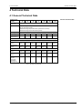
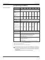
The variable 318 Nm is below the threshold value of 400 Nm listed in the table
for adding on an RKP 63 to an RKP 63.
Design of the second through drive
V3 ⋅ p3
V4 ⋅ p4 ⎞
- + ------------------M 2 = 1 ,59 ⋅ ⎛ ------------------η hm4 -⎠
⎝ η hm 3
M2 = 1,59 · (32 · 150 / 93 + 16 · 50 / 90) Nm
M2 = 96 Nm
Again in this case, the variable 96 Nm is below the respective threshold value
of 400 Nm for the through drive for the arrangement of an RKP-II 63 to an RKPII 32.
Design of the third through drive
ζ
In the same manner, 14 Nm is obtained for the torque required to drive the
added on gear pump. As a result, the through drives of these pump
arrangements are permissible with the specified pressure values.
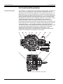
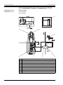
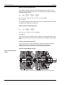
Section Diagram Multiple Pumps
Section Diagram Multiple
Pumps
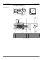
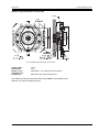
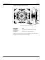
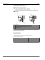
Fig. 19: Radial Piston Pump with Heavy Through Drive and Add-On Radial Piston Pump
38
User Manual RKP-II (CA53461-001; Version 2, January 2010)
© 2010 Moog GmbH