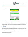
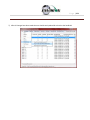
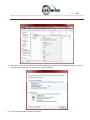
Download Envision EN-780e Specifications

Transcript
Envision™ Landfill Gas Analyzer
865 West Liberty, Suite 220, Medina, Ohio
06/19/2014
Page |2
1
INTRODUCTION ..................................................................................................................................................................... 4
2
THE ENVISION® SYSTEM ........................................................................................................................................................ 4
3
SAFETY .................................................................................................................................................................................. 6
4
CERTIFICATION ...................................................................................................................................................................... 7
5
TRIMBLE® HANDHELD COMPUTER PREPARATION ................................................................................................................ 8
5.1
5.2
5.3
5.4
5.5
6
TURNING ON THE TRIMBLE HANDHELD COMPUTER .......................................................................................................................... 8
TURNING OFF THE TRIMBLE HANDHELD COMPUTER ......................................................................................................................... 8
BACKLIGHT AND POWER SETTINGS ................................................................................................................................................ 8
ENABLE BLUETOOTH® .............................................................................................................................................................. 14
ENABLE GPS .......................................................................................................................................................................... 16
ENVISION® GAS ANALYZER APPLICATION ........................................................................................................................... 19
6.1
SOFTWARE SCREEN PROPERTIES ................................................................................................................................................. 20
6.2
“LOGIN SCREEN” - LOGGING TO THE ELKINS GAS ANALYZER SOFTWARE ............................................................................................. 20
6.3
CONNECTING TO AND DISCONNECTING FROM THE ENVISION® GAS ANALYZER..................................................................................... 23
6.3.1 Connecting to the Envision® Gas Analyzer ..................................................................................................................... 23
6.3.2 Bluetooth Connection ..................................................................................................................................................... 23
6.3.3 Serial Connection (if desired).......................................................................................................................................... 28
6.3.4 Disconnecting from the Envision® .................................................................................................................................. 29
6.4
MAIN MENU .......................................................................................................................................................................... 30
6.5
CALIBRATION .......................................................................................................................................................................... 30
6.5.1 Zero Gas Calibration ....................................................................................................................................................... 32
6.5.2 Span Gas Calibration ...................................................................................................................................................... 41
6.5.3 Pressure Sensor Calibration ............................................................................................................................................ 46
6.5.4 Storing a Calibration File ................................................................................................................................................ 52
6.6
ANALYZE................................................................................................................................................................................ 54
6.6.1 Select ID.......................................................................................................................................................................... 54
6.6.2 Analyze ........................................................................................................................................................................... 61
6.7
READ PRESSURES..................................................................................................................................................................... 73
6.8
COMMENTS............................................................................................................................................................................ 78
6.9
VIEW AND STORE DATA ............................................................................................................................................................ 80
6.10
UTILITIES ............................................................................................................................................................................... 82
6.10.1
Well ID Maintenance ................................................................................................................................................. 83
6.10.2
View Missed Well Report ......................................................................................................................................... 101
6.10.3
Meter Status ............................................................................................................................................................ 102
6.10.4
License Manager ...................................................................................................................................................... 104
6.10.5
Set Options............................................................................................................................................................... 106
6.10.6
Restore All Factory Cal ............................................................................................................................................. 108
6.11
STORED DATA....................................................................................................................................................................... 109
6.12
O&M MANUAL .................................................................................................................................................................... 110
Page |3
6.13
7
THE ENVISION® GAS ANALYZER CONFIGURATION EDITOR SOFTWARE (GAC).................................................................... 112
7.1
7.2
7.3
7.4
7.5
7.6
7.7
7.8
7.9
7.10
7.11
7.12
8
EXITING THE GAS ANALYZER SOFTWARE..................................................................................................................................... 111
LOADING THE APPLICATION...................................................................................................................................................... 112
OPENING THE GAS ANALYZER CONFIGURATION EDITOR FOR THE FIRST TIME ..................................................................................... 112
ADD A SITE, TECHNICIAN, VALVE ADJUSTMENT, WELL CONDITION AND/OR WELL REPAIR................................................................... 113
ADD A MONITORING POINT...................................................................................................................................................... 115
CLONING WELLS .................................................................................................................................................................... 120
DELETE WELLS ...................................................................................................................................................................... 123
COMBINING WELLS FROM ANOTHER ID SET................................................................................................................................. 125
SAVE FILE............................................................................................................................................................................. 127
ID SET STORED LOCATION ON PC .............................................................................................................................................. 128
TRANSFERRING ID SETS BETWEEN TRIMBLE AND THE PC ............................................................................................................... 128
IMPORTING GEM CONFIGURATION FILES................................................................................................................................... 133
PRINT PREVIEW..................................................................................................................................................................... 134
CONNECTING THE TRIMBLE HANDHELD COMPUTER TO A PC............................................................................................ 135
8.1
WINDOWS MOBILE DEVICE CENTER.......................................................................................................................................... 135
8.2
WINDOWS XP MACHINES ....................................................................................................................................................... 139
8.2.1 Download Active sync .................................................................................................................................................. 139
8.3
TRANSFERRING FILES .............................................................................................................................................................. 144
8.3.1 Directory Structure ....................................................................................................................................................... 144
8.3.2 Copy Files from PC to Trimble....................................................................................................................................... 146
8.3.3 Copy File from Trimble to PC ........................................................................................................................................ 149
9
ERRORS AND TROUBLESHOOTING .................................................................................................................................... 152
9.1
9.2
10
®
ENVISION MAINTENANCE ................................................................................................................................................ 155
10.1
10.2
11
FACTORY MAINTENANCE ........................................................................................................................................................ 155
FIELD MAINTENANCE ............................................................................................................................................................. 155
WARRANTY ....................................................................................................................................................................... 157
11.1
11.2
12
®
ENVISION ERROR CONDITIONS: ............................................................................................................................................... 152
OTHER ERROR CODES ............................................................................................................................................................. 153
ENVISION® WARRANTY .......................................................................................................................................................... 157
TRIMBLE HANDHELD WARRANTY.............................................................................................................................................. 157
PROBLEMS AND POTENTIAL SOLUTIONS ........................................................................................................................... 159
12.1
PROBLEMS AND POTENTIAL SOLUTIONS FOR ENVISION & TRIMBLE ................................................................................................. 159
®
13
ENVISION SPECIFICATIONS ............................................................................................................................................... 160
14
CONTACT INFORMATION .................................................................................................................................................. 163
Page |4
1 Introduction
Elkins Earthworks® would like to welcome you to the Envision® gas analyzer system. The Envision® gas analyzer, designed by
Elkins Earthworks® is manufactured here in the United States. The equipment was designed for the field technician as well as
project managers. The Envision® gas analyzer is a two part system, the sensor unit (the Envision®) and the handheld PC (the
Trimble®). This unique pairing makes field activities more productive by giving the user the ability to expand functionality by
using GPS, bar-coding, and other features that Windows Mobile® can offer.
2 The Envision® System
The Envision® gas meter is a unique field instrument utilized primarily for the measurement of CH 4, CO2, O2, pressure,
temperature, and flow within landfill gas and bio-gas collection systems. The Envision® gas analyzer package is comprised of
two components:
Trimble® Handheld Computer
The first component is a highly ruggedized field computer from Trimble. The Trimble series handhelds are all-in-one field
computers for GIS (Geographic Information System) data collection and mobile GIS applications, combining a handheld
computer powered by the Windows Mobile 6 or 6.1 operating system. The Trimble series handhelds connect to the
Envision® via Bluetooth® or via serial cable. The Trimble series handhelds come standard with Bluetooth and 802.11.
Optional features may also be selected such as GPS, barcode scanner, and/or an internal camera. The Trimble field computer
utilizes the Elkins Earthworks® Gas Analyzer proprietary software to operate the Envision® gas analyzer.
Page |5
The Envision® (Gas Analyzer Unit)
The Envision® gas analyzer houses the gas and pressure sensors. The gas analyzer utilizes infrared sensors to measure CH4
and CO2. The Envision® uses an electrochemical cell to measure O2 concentration and an accurate thermistor temperature
probe to measure wellhead gas temperatures. Data generated by the Envision® gas analyzer is relayed to the Trimble® via
Bluetooth or serial cable several times per second.
Page |6
Sample Ports
The Envision® gas analyzer has four (4) ports located on the front of the unit.
From the right to the left:
Calibrate/Static/Sample port – This port is used to calibrate the unit with calibration gas, to measure static wellhead
pressure, and to sample for gas quality.
Impact Port – This port is used to generate a differential pressure for calculating flow. Do not connect pressurized
calibration gasses to this port.
Available – This port is used to acquire an available (system) vacuum at the monitoring port. Do not connect pressurized
calibration gasses to this port.
Exhaust – This port is used to exhaust the gasses that are pumped through the sample train for measurement. Only connect
an exhaust hose to this port. Do not apply pressure to the exhaust port.
3 Safety
Landfill gas is normally safely extracted from landfills and conveyed to appropriate control devices. However, during the
course of monitoring each extraction point, exposure may occur. As such, it is important to follow all site-specific safety
protocols when monitoring. Typically a work at a landfill requires site specific health and safety plans. While performing
monitoring at a landfill, the user should be aware of the items included in that site specific health and safety plan. While the
Envision® gas analyzer is not for use in explosive atmospheres, it is important to know that all personal protection equipment
Page |7
and safety protocols as appropriate must be used when using the instrument. All vents on the meter are designed to exhaust
to the atmosphere. Since landfill gas contains methane, no smoking is permitted while using the instrument. Calibration
gases must be handled with utmost care and with adequate ventilation.
It is the sole responsibility of the user of the Envision® gas analyzer and the Trimble handheld PC to determine the
appropriate location that either unit can be utilized within as monitoring conditions may change. The Envision® gas analyzer
and the Trimble handheld PC are not intended for use in confined space entries but for the continuous monitoring of gasses
within a landfill gas collection system.
4 Certification
This version of the Envision is not rated for use in explosive atmospheres. It is important that this manual be followed closely
and that any repair to the Envision® gas analyzer is made at the approved Elkins Earthworks® repair facility. Opening the
Envision® gas analyzer and breaking the housing warranty seals may result in voiding the unit’s warranty as well as
compromising the unit’s safety.
Both the Trimble handheld PC and the Envision® gas analyzer meet the FCC regulations for Class A Digital Devices Part 15,
Subpart B, Sections 15.107b & 15.109b
Page |8
5 Trimble® Handheld Computer Preparation
The Trimble handheld computer is the prime driver for the Envision® gas analyzer. The Trimble handheld computer, provided
with the Envision® gas analyzer package, has already been prepared for field use. A screen protector has already been
applied to your Trimble unit. An extra screen protector has been included in the packaging.
The operational software for the Envision® Gas Analyzer has been installed at the factory. The Trimble handheld computers
operate on the Microsoft Mobile 6.0, 6.1, or 6.5 operating systems. The features on the Trimble are similar to those on the
standard Microsoft XP and Vista operating systems found on many desktops and laptops. For general information on the
features of the Trimble Nomad and Windows Mobile 6.0, 6.1, or 6.5 please refer to the supplemental information provided in
the packaging of the Envision® Gas Analyzer.
5.1
Turning on the Trimble Handheld Computer
To turn on the Trimble handheld computer the user must press the green power button located at the lower left side of
the Trimble keypad.
5.2 Turning off the Trimble Handheld Computer
1) Press the green power button for two seconds
2) Tap the shutdown button on the touch screen
3) Tap yes on the popup screen if you agree with the warning message
5.3 Backlight and Power Settings
Elkins Earthworks® has already adjusted your Trimble handheld computer for the following backlight and power settings:
Page |9
Parameter
Battery Power
External Power
Backlight*
Never turns off
Never turns off
Backlight Brightness
100%
100%
Keypad on Time
1 minute
1 minute
Keypad Brightness
100%
100%
Hibernation**
Never
Never
* If the user changes the backlight setting the Envision® will lose Bluetooth connection when the unit enters and
recovers from the backlight being powered on and off. The unit will regain Bluetooth connection almost instantly.
** Hibernation mode will cause the Envision® to lose connection and will need to be reconnected once the Nomad is
turned back on. Elkins Earthworks® recommends that these settings remain as set upon delivery.
P a g e | 10
Changing Backlight Settings
If the user would like to change these settings then follow the steps below:
1) Turn on the Trimble handheld computer by pressing the green power button on the handheld computer keypad.
2) On the touch screen tap the “Start” button in the upper left hand corner of the touch screen
P a g e | 11
3) Tap “Settings”
4) Next tap “System”
P a g e | 12
5) Next tap “Backlight”
6) On the “Battery Power” and “External Power” screens, uncheck the “Turn off backlight if device is not used for” box.
P a g e | 13
7) Tap on the Brightness tab at the bottom of the screen.
8) Increase the brightness to 100%
9) At the bottom of the “Brightness” screen select “Power” in the adjust power setting to conserve power.
P a g e | 14
10) Select the “Advanced” tab then uncheck the box “Turn off device if not used for”. This will keep the unit from going
into hibernation. If the Trimble handheld computer goes into hibernation it will lose connection with the Envision®
gas analyzer.
11) Exit by tapping the “OK” button twice.
5.4 Enable Bluetooth®
The primary way to connect with the Envision® gas analyzer is via Bluetooth® connection. The unit ships from the factory
with the Bluetooth enabled. Just in case the Bluetooth becomes disabled, tap the Bluetooth icon on the Main Windows
Screen. The gas analyzer software will automatically turn the WLAN (wireless network) off to prevent it from interfering
with the Bluetooth connection.
P a g e | 15
Next, on the Wireless Manager Screen tap the Bluetooth button and the Bluetooth will activate.
P a g e | 16
5.5 Enable GPS
The Envision® gas analyzer system software is designed to utilize GPS to locate monitoring points. Units that are
purchased with the GPS option require no setup to enable the GPS feature. The software developed for the Envision® gas
analyzer automatically turns the GPS on and off when needed. Do not change any of the GPS settings in the Trimble
handheld computer. The Trimble handheld computer has been shipped with default settings. If the GPS fails to connect
the user should check the GPS in the following manner:
1) Tap the “Start” button in the upper left corner of the screen and tap settings
2) Tap System and then External GPS
P a g e | 17
3) Verify GPS program port is set to COM 3
4) GPS Hardware Port is set to COM2 and BAUD rate 9600
P a g e | 18
5) Verify that this box is checked too.
P a g e | 19
6 Envision® Gas Analyzer Application
The” Elkins Gas Analyzer” program is the software developed to run the Envision® gas analyzer. To activate the Gas
Analyzer program follow the steps below:
1) Click Start in the upper left hand corner of the screen and tap the “Elkins Gas Analyzer” button in the drop down
menu.
2) The application will start and the “Login Menu” will appear
3) If the “Elkins Gas Analyzer” program is already running then the application will open to the last screen that the user
was viewing.
P a g e | 20
6.1
Software Screen Properties
The detail below illustrates the main features common to each screen of the Elkins Gas Analyzer Program.
6.2 “Login Screen” - Logging to the Elkins Gas Analyzer Software
Once the Elkins Gas Analyzer program is started from the “Start Menu” the “Login Menu” will appear. This screen is
intended to allow the user to login to the Elkins Gas Analyzer program.
P a g e | 21
1) Select the Desired ID set and the name of the Technician who will be using the Envision® gas analyzer from the drop
down menu located at the center of the “Login Menu” screen. ID sets may be added to this drop down menu by
utilizing the “Elkins Earthworks® Configuration Editor” software that may be installed on your personal computer.
The “Elkins Earthworks® Configuration Editor” software is provided on the Elkins Earthworks® software Flash drive
included in the original packaging of the Envision® gas analyzer. Technician Names may be added directly from the
drop down list on the Login Menu.
P a g e | 22
2) Verify that the date and time is correct as displayed on the login screen
3) If date and/or time is incorrect then tap the “Set Time/Date” button
4) The “Set Time/Date” screen will appear and you may then adjust to the correct date and/or time
P a g e | 23
5) Tap the “Set” button when the date and time have been corrected. This will return the user to the Login Screen.
6) If the user name and time are now correct then tap the “Login” button at the bottom of the screen
6.3 Connecting to and Disconnecting from the Envision® Gas Analyzer
6.3.1
Connecting to the Envision® Gas Analyzer
The user can connect to the Envision® gas analyzer in one of two ways, by Bluetooth or serial connection.
6.3.2
Bluetooth Connection
Once the user is logged in, the user can now search for and connect to an Envision® gas analyzer.
1) On the Trimble handheld computer make sure that the “Select Meter” screen is displayed
P a g e | 24
2) Turn on the Envision® gas analyzer by pressing the power button on the front of the Envision® gas analyzer
3) The Envision® gas analyzer will maintain a solid green light next to the power button
4) Next press the Bluetooth® button on the face of the Envision® gas analyzer. The blue light on the Envision® gas
analyzer will blink now that it is discoverable and can allow the Trimble handheld computer to find it.
5) The user should now tap the “Search” button on the “Select meter” screen on the Trimble handheld computer.
P a g e | 25
6) The Trimble handheld computer screen will display “Searching…” above the “Meters” box and will change to “Select
Meter to connect” once the Envision® gas analyzer is discovered.
7) The Envision® gas analyzer should be displayed in the box titled “Meters”. Each discoverable Envision® unit should
appear and will be defined by the name Elkins Envision® followed by the units serial number
P a g e | 26
P a g e | 27
8) Select the desired analyzer by tapping the Envision® Meter ID and then tapping “Connect”
9) Once the connection is made the words “Connected to ….” will be displayed in green above the “Meters” screen.
The blinking blue light on the Envision® gas analyzer will stop blinking and will now show solid blue. The connection
symbol in the yellow header box on the Trimble handheld computer screen will now be multicolored indicating a
connection with the Envision® gas analyzer. The battery strength indicator located in the yellow header box will now
display the approximate battery level of the Envision® gas analyzer.
P a g e | 28
10) Once connected, tap the “Main Menu” button on the lower right hand corner of the screen.
6.3.3
Serial Connection (if desired)
If the user has problems with the Bluetooth link or desires to make a direct wired connection to the Envision® gas
analyzer, the user may use a standard RS232 Serial cable connection. This connection requires the RS232 boot on
the bottom of the Trimble handheld computer.
1)
2)
3)
4)
5)
Tap “Login” on the “Login Menu”
Connect the Trimble handheld computer to the Envision® gas analyzer with the RS232 serial cable
Select “Serial Connection” in the analyzer display area.
Tap the button connect and the word “Connected to ….”” will be displayed above the “Meters” screen.
Once connected tap the “Main Menu” button on the lower right hand corner of the screen.
P a g e | 29
6.3.4
Disconnecting from the Envision®
To disconnect from the Envision® gas analyzer follow the steps listed below:
1)
From the “Main Menu” tap the “Select Meter” button on the lower left corner of the touch screen
P a g e | 30
2)
Tap the “Disconnect” button
6.4 Main Menu
The “Main Menu” is the user’s access point for all of the features included in the Elkins Gas Analyzer software. On this screen
the user may select any one of the functions indicated on the buttons or the user may return to the “Select Meter” screen by
tapping the “Select Meter” button in the lower left corner of the touch screen. The following sections will walk the user
through each of the functions indicated on the “Main Menu” screen.
6.5 Calibration
The Envision® gas analyzer has three internal gas measurement sensors (CH4, CO2 and O2) and five pressure sensors that have
been calibrated in the factory. The factory calibration results are stored within the Envision® gas analyzer and can only be
altered in the factory. The Envision® gas analyzer should be field calibrated prior to each monitoring event. The field
calibration file is stored within the Trimble handheld computer.
To enter the calibration area of the software tap the “Calibrate” button on the “Main Menu” screen. The calibration process
of the Envision® gas analyzer was built to be simple for the field user. Follow the calibration procedure described below to
accurately calibrate the Envision® gas analyzer.
P a g e | 31
Each gas sensor should be calibrated with a zero gas and then a span gas. The order in which the gas sensors are calibrated is
not important but the zero point of each gas must be calibrated before the span of that gas can be calibrated. It is also
recommended that when one gas sensor is calibrated that all sensors should be calibrated for zero and span.
Below is a brief description of the calibration menu:
P a g e | 32
6.5.1
Zero Gas Calibration
Before a span gas can be calibrated the zero gas calibration must be performed.
1)
Tap the “Zero” button of the gas that is to be calibrated. This action will take the software to the “Calibration …
Zero” screen
P a g e | 33
2) The user now has the ability to scan the barcode on the calibration cylinder. Tap the “Scan Barcode” button and
aim the scanner laser at the barcode on the calibration gas cylinder being utilized. The barcode number will
automatically populate the “Calibration Gas Cylinder #” text box. The user can manually type in the bottle lot#
using the numeric keypad on the Trimble or the user may proceed without entering a cylinder number. This
data will be recorded in the calibration .csv file that is stored during the calibration process.
3) Attach the calibration gas to the Static sample port located on the front of the Envision® gas analyzer and open
the regulator valve. Elkins Earthworks® strongly recommends the use of a Demand Flow regulator. If using a
tunable regulator, use a setting of .5 lpm.
Warning – attach the calibration gas only to the Static port. Do not attach the calibration gas to the Exhaust,
Impact or Available ports. Pressures above 200” H20 on any port other than the static pressure port may result
in a damaged pressure sensor.
P a g e | 34
4) Tap the “Start Calibration” button. This action will turn on the sample pump and will change the Trimble
handheld computer display.
P a g e | 35
5) For the first 20 seconds the “Calibration Status” will display “Initializing Gas Sensor”. The “Calibrate” and
“Restore Factory Calibration” buttons will stay inactive during the sensor warm-up phase. If your meter has
received a firmware update as of 9/1/2013 the sensors will always stay on, no longer requiring the 20 second
initialization. However, the O2 sensor does not require a warm-up time and therefore never needs to go
through the Initializing gas sensor countdown.
P a g e | 36
6) The “Calibration Value” located in the middle of the touch screen should be 0.00%.
P a g e | 37
7) Once the sensors are initiated and warmed up the “Current Value” will fluctuate. When the “Current Value” is
less than 1% the Calibration status will display “Ready to Calibrate”. “Ready to Calibrate” does not mean that
the sensor has stabilized but that the unit is within the 1% tolerance allowed when zeroing. Tap the “Calibrate”
button once the current value has stabilized.
a.
If the “Current Value” is between 0% and 1% then your Trimble handheld computer will adjust and store
your calibration once the user taps the “calibrate” button.
P a g e | 38
b.
If the “Current Value” is greater than 1% then the Trimble handheld computer will display the following
message “Verify calibration gas value and/or restore factory calibration”. The user may restore the factory
calibration by taping the “Restore Factory Calibration” button on the “Calibration … Zero” screen. The user
should then try to recalibrate. If the unit will not calibrate then the user should contact technical support at
Elkins Earthworks® at 330-725-7766.
P a g e | 39
8) The pump will continue to run and the sensors will continue to monitor until the user returns to the
“Calibration” menu by taping the “Calibration” button in the lower right hand corner of the touch screen.
P a g e | 40
9) Now that the Trimble handheld computer has returned to the “Calibration Menu” the user will notice that the
parameter that has been calibrated is now highlighted in green.
10) The user may now select the next gas to calibrate.
P a g e | 41
6.5.2
Span Gas Calibration
Once the Zero point has been calibrated for the desired gas, a calibration can then be performed on the span gas.
1) On the “Calibration Menu” tap the “Span” button of the gas that is to be calibrated. This will take the user to
the “Calibration … Span” screen
2) On this screen there are two preset calibration gas values and one text box that the user can type in a user
defined calibration gas value using the touch screen keyboard or numeric keypad. If selecting a user defined gas
quality, the user must enter a value 0.1% to 100%.
P a g e | 42
3) If the user types in a span gas value, he must first type in the desired gas quality then tap the “User Defined”
button. Once the user taps “User Defined” or either one of the two predetermined gas qualities, the screen will
then change to the “Calibration … Span” screen.
4) The user now has the ability to scan the barcode on the calibration cylinder. Tap the “Scan Barcode” button and
aim the scanner laser at the barcode on the calibration gas cylinder being utilized. The label number will
automatically populate the “Calibration Gas Cylinder #” text box. The user can manually type in the bottle lot#
using the numeric keypad on the Trimble or the user may proceed without entering cylinder #. This data will be
recorded in the calibration .csv file that is stored at the end of the calibration process.
5) Attach the calibration gas to the Static sample port located on the front of the Envision® gas analyzer and open
the regulator valve. Elkins Earthworks® strongly recommends the use of a Demand Flow regulator. Warning –
attach the calibration gas only to the Static port. Do not attach the calibration gas to the Exhaust, Impact or
Available ports. Pressures above 200” H20 on any port other than the static pressure port may result in a
damaged pressure sensor.
P a g e | 43
6) Tap the “Start Calibration” button. This action will turn on the sample pump and will change the display.
7) For the first 20 seconds the “Calibration Status” will display “Initializing Gas Sensor” and will count down 20
seconds. The “Calibrate” and “Restore Factory Calibration” buttons will stay inactive during the sensor warm-up
phase. When calibrating the O2 the user will not need to go through the Initializing Gas Sensor countdown.
P a g e | 44
8) The “Calibration Value” located in the middle of the touch screen should be the same as the gas quality that is
being used for calibration and will not fluctuate.
9) Once the sensors are initiated and warmed up the “Current Value” will fluctuate. When the “Current Value” is
between 0% and 20% (relative) of the calibration gas value the Calibration status will display “Ready to
Calibrate”. Tap the “Calibrate” button once the current value has stabilized.
a.
If the “Current Value” is between 0% and 20% (relative) of the calibration gas value then the Trimble
handheld computer will adjust and store your calibration once the user taps the “calibrate” button.
P a g e | 45
b.
If the “Current Value” is greater than 20% (relative) of the calibration gas value, then the Trimble handheld
computer will display the following message “Verify calibration gas value and/or restore factory calibration”.
The user may restore the factory calibration by taping the “Restore Factory Calibration” button on the
“Calibration … Span” screen. The user should then try to recalibrate.
c.
If the Verify warning still appears after restoring factory calibration and verifying the calibration gas then the
user should contact Elkins Earthworks® technical support at 330-725-7766.
P a g e | 46
10) Now that the Trimble handheld computer has returned to the “Calibration Menu” the user will notice that the
parameter that has been calibrated is now highlighted in green.
11) The user may now select the next gas to calibrate
6.5.3
Pressure Sensor Calibration
The Envision® gas analyzer has 5 internal pressure sensors. These sensors should be field calibrated at the beginning and
periodically during the monitoring event. The pressure sensors may be zeroed from two different locations in the Elkins
Earthworks® Analyzer software.
From the “Calibration Menu”
1) Tap the “Pressure Zero” button. The screen will change to the “Pressure Calibration” screen
P a g e | 47
2) On the “Pressure Calibration” screen allow the pressures in the 5 pressure blocks to stabilize.
3) Ensure that the sample fittings are disconnected from the wellhead and shielded from wind
4) Tap the “Zero Transducers” button on the lower center part of the touch screen.
P a g e | 48
5) The values in the green pressure boxes should now read 0.00” H2O. Due to the high sensitivity of the sensors
the values may still fluctuate but they should be close to the target value.
P a g e | 49
6) The user may also enter the current Barometric pressure by tapping the up and down arrows next to the
Barometric Pressure. This will be used in the flow calculations generated by the unit.
7) The user may also restore the factory calibration by tapping the “Restore Factory Calibration” button.
P a g e | 50
8) Tap the “Calibration” button on the lower right of the screen to return to the main “Calibration” screen.
The pressure sensor calibration menu is also accessible from the pressure measurement screen in the analyze portion of
the software. On the read “Pressures” screen tap the “Calibrate Sensors” button. This action will take you to the
pressure sensor calibration screen that was just described in the previous section.
P a g e | 51
Follow the same pressure calibration procedure as detailed in the previous section then tap the Analyze button in the
lower right corner of the screen.
Warning: Never apply vacuums greater than -200”H20 or pressure greater than +200”H2O to any of the pressure sensors
during calibration or measurement activities. These extreme pressures can damage the pressure sensors within the
Envision® gas analyzer.
P a g e | 52
6.5.4
Storing a Calibration File
Once all of the calibration gases have been calibrated the user can select the option to “Store Calibration File”. This
feature will generate a .csv file with all of the calibration information generated during the calibration activity.
If the user has failed to calibrate all of the parameters a warning screen will appear and will indicate “Not all calibrated”.
This is a warning box so that the user can go back and calibrate the remaining parameters, if desired. If the user taps the
“OK” box in the warning message it will return the screen back to the “Calibration Menu” so that the remaining
parameters can be calibrated. If the user does not calibrate the remaining parameters and taps the “Store Calibration
P a g e | 53
File” button again the unit will store a “Calibration File” but will place NA in the fields that were not calibrated. Elkins
Earthworks® recommends that each parameter be calibrated at least once during each monitoring event.
Once the “Store Calibration File” button is selected the Trimble handheld computer will store the calibration file in the
Trimble handheld computer in File Explorer: my documents/Elkins Earthworks/calibration. The file is named as such:
meter serial number_month-date-year_time (i.e. 000108_7-20-2008_1028).
P a g e | 54
6.6 Analyze
The Analyze feature of the Envision® software allows the user to measure and record gas qualities, associated pressures and
comments for selected monitoring points. To enter the “Analyze” portion of the software go to the main menu and tap the
“Analyze” button. The Trimble handheld computer will automatically progress to the “Select ID” screen.
6.6.1
Select ID
To make it easier for a user to locate and identify a well or location to monitor, the Envision® software utilizes three
different search methods: manual, GPS or barcode scanner. In Section 7 there are specific instructions on how to
configure an ID set utilizing the “Elkins Earthworks® Gas Analyzer Configuration Editor”.
P a g e | 55
6.6.1.1 Manually Select ID
On the “Select ID” screen you may manually select the monitoring point by following the instructions below:
1) Use the scroll text boxes labeled “Site” and “ID” to locate the monitoring point that is to be monitored.
P a g e | 56
2) If the “Site” or “ID” is not stored in the ID list, the user can manually create a Site and/or ID within the “Well ID
Maintenance” feature accessible via the “Well ID Maintenance” button at the bottom of the “Select ID” screen.
Instructions on how to Use the “Well ID Maintenance” function can be found in 6.10.1 “Well ID Maintenance”.
P a g e | 57
3) Once the correct ID is selected the user should tap the “Purge” button. The sample pump will turn on and the
button will turn green. The timer will count down 90 seconds or until the O2 percent in the meter is at least 18%
then the pump will turn off. The purge cycle may end if either the Envision® meter detects that the sample train
is clear of methane or the user taps the “Purge” button again.
P a g e | 58
4) Once the purge is complete keep your sample trains disconnected and shielded from the wind then tap the
“Zero Pressures” button. The user can also decide to skip the “Zero Pressures” feature and tap the “Analyze”
button on the bottom right corner of the screen.
5) Once the pressures have been calibrated tap the “Analyze” button in the lower right corner of the “Pressure
Calibration” screen.
P a g e | 59
6.6.1.2 GPS Selection of ID
If the user desires to locate the monitoring point via GPS then follow the instructions detailed below:
1) Stand at the location to be monitored – The first connection may take several 4 minutes for the GPS to lock after
the Nomad is first turned on. Each location after this should be instantaneous.
2) Tap the GPS button on the Trimble handheld computer’s touch screen.
3) Once the “GPS” button is pushed a status message will be displayed above the Site text box that will indicate
“Reading GPS”
4) Once the GPS has verified a monitoring point the status will change to “Site/ID selected by Barcode/GPS”
5) The Trimble handheld computer will automatically populate the “Site” and “ID” text box with the nearest
monitoring point.
6) If the GPS does not find a monitoring point then the status will change to “Failed to find Barcode/GPS match”. If
the ID is known, the user can manually select the “Site” and “ID” then tap the “Well ID Maintenance” button to
mark the GPS coordinates for that location. Instructions on how to use the “Well ID Maintenance” function can
be found in section 6.10.1.
7) If sample points are located within 30 feet of each other then the GPS function will select the closest point to
your location.
6.6.1.3 Barcode Selection of ID
If you desire to select the well to be measured by barcode please follow the instructions below:
1) Walk up to the point to be monitored
2) Locate the barcode on the item to be monitored
P a g e | 60
3) On the “Select ID” screen tap the “Barcode” button on the Trimble handheld computer touch screen and aim the
laser scanner at the barcode
4) A status message will be displayed above the “Site” that will indicate “Scanning Barcode”
P a g e | 61
5) Once the barcode has been verified the status will change to “Site/ID selected by Barcode”
6) The Trimble handheld computer will automatically populate the “Site” and “ID” text box with the correct
monitoring point.
7) If the barcode does not find a monitoring point then the status will change to “Failed to find Barcode/GPS
match”. If the ID is known, the user can manually select the Site and ID then tap the “Well ID Maintenance”
button to mark the barcode for that location. Instructions on how to Use the “Well ID Maintenance” function
can be found in section 6.10.1.
6.6.2
Analyze
This feature allows the user to measure the gas qualities and pressures for a selected sample point. The “Analyze”
screen is accessed by pressing the “Analyze” button on the “Select ID” screen.
P a g e | 62
6.6.2.1 Analyze Screen buttons
6.6.2.1.1 Pump
This button activates the sample pump located within the Envision® gas analyzer.
The button is red when the pump is off and green when activated. The default on time for the pump is 600
seconds. To activate the pump tap the “Pump” button once. The sensor will then go through a 20 second
warm-up before actual gas values will appear. The pump may be turned off by tapping the “Pump” button
again. If the pump is turned off then the gas values will return to the default “NA”. To lock the gas values the
user must tap the “Lock Readings” or “Read Pressures”. The pump time can be changed within the
Configuration Editor as described in section 7.
P a g e | 63
6.6.2.1.2
Read Pressures
The Envision® unit measures Available, Applied, and Differential pressures. In order to view and record these
pressures the user must go to the “Read Pressures” screen.
P a g e | 64
This button takes the Trimble handheld computer to the “Pressures” screen.
P a g e | 65
6.6.2.1.3 Previous Data
If the user desires to view data previously recorded on the Trimble handheld computer then the Previous Data
button should be tapped.
P a g e | 66
This button will take the Trimble handheld computer to the “View History” screen. The “View History” screen
will display any historical well data for the selected ID located in the site’s current month output file located on
the Trimble handheld computer.
To return to the “Analyze” screen tap the Analyze button in the bottom left hand corner of the screen.
P a g e | 67
6.6.2.1.4 Browse File
The “Browse File” button will take the Trimble handheld computer to the File Explorer.
This will allow you to search for previously stored .csv (comma separated variable) files for viewing. Applications
are available for the Trimble handheld computer that will allow the user to view .csv files.
To return to the “Analyze” screen tap the X in the upper right hand corner of the screen.
P a g e | 68
6.6.2.1.5 Lock Readings
The “Lock Readings” button is designed to lock the gas values and to turn off the pump. This feature
locks the readings so if you decide to come back to this screen your readings will not change. This
feature does not actually “Store” the gas qualities into the .csv file.
After the “Lock readings” button is tapped the button will change to “readings saved”. The values are
now locked. The values can be unlocked by tapping the pump button. In order for the data to be
stored to a .csv file the user must tap “Store” on the last analyze screen.
P a g e | 69
6.6.2.1.6 Next ID
This button will allow you to select another ID without having to proceed through the entire sample procedure.
However this will not store any of the data that you have gathered for the current ID.
6.6.2.1.7 Main Menu
This button will exit the user from “Analyze” and take the user back to the “Main Menu”. However this will not
store any of the data that you have gathered for the current ID.
P a g e | 70
6.6.2.2 Gas Quality and Gas Quality Ratios
The Envision® gas analyzer measures concentrations of three gases: CH4, CO2 and O2. The balance gas is calculated by
subtracting the total of these three gas qualities from 100%.
6.6.2.2.1 Gas Qualities
CH4 - Methane
CH4 is measured via an internal Infrared sensor. The measurement range of the sensor is 0-100% CH4.
CH4 – LEL (lower Explosive Limit)
By tapping the CH4 box the Trimble handheld computer will display the CH4 LEL%. The user can return
to the standard CH4% by tapping the CH4 box again. Note: 100% LEL is equal to 5% CH4.
CO2 – Carbon Dioxide
CO2 is measured via an infrared sensor. The measurement range of the sensor is 0-100% CO2.
O2 - Oxygen
O2 is measured via an electrochemical sensor. The measurement range of the sensor is 0 – 22% O2.
Balance Gas
Balance gas is a calculated value. It is calculated as follows:
Balance gas = 100%- CH4- CO2- O2
P a g e | 71
6.6.2.2.2 Gas Ratios
Balance/ O2


Results near “4” indicate a direct air leak into the sample train, sample fitting or
wellhead.
User should be familiar with interpreting the range of ratios for Balance/ O2.
Information is available within the SWANA Landfill Gas O&M Manual available at
www.swana.org.
CH4/ CO2



Ratio lower than 1.1 may indicate potential for stressed conditions on a landfill gas
well.
The ratio may assist in drawing attention to different phases of landfill gas
production.
User should be familiar with interpreting the range of ratios for CH4/ CO2.
Information is available within the SWANA Landfill Gas O&M Manual available at
www.swana.org.
P a g e | 72
6.6.2.3 Color Definitions
The Elkins Gas Analyzer software has been programmed to help the user make tuning decisions by using acceptable
ranges which have been set up using the Configuration Editor software. When the gas sensor is in the acceptable range
the gas quality text box will turn from red to green. The color key can be displayed by touching the gas quality text box.
Tap “OK” to close the color key.
These ranges are programmable for each well by utilizing the Configuration Editor as detailed in section 7.
P a g e | 73
The software is also programmed to detect when the gas sensors have stabilized. When the gas sensor has stabilized the
gas quality text box will turn from clear to green. The color key can be displayed by touching the sensor title. Tap “OK”
to close the color key.
The user may progress to the next screen by pressing the “Read Pressures” button. The user may also elect to go back to
the main menu by tapping the “Main Menu” button.
6.7 Read Pressures
The Envision® gas analyzer is built with five internal pressure sensors. The software is programmed to use the sensor that
is the most precise for the range being measured. Listed below are the sensors and their ranges.
Pressure Sensor
Low Pressure
(“H2O)
Available
NA
Applied
-5 to +5
High
Pressure
(“H2O)
-138 to
+138
-138 to
+138
P a g e | 74
Differential
-5 to +5
-30 to +30
When initially entering the “Pressures” screen from the “Analyze” screen the user will notice that the Initial pressures are
visible.
When the pressure sensors are in the acceptable programmed range, as programmed by the user in the Configuration
Editor, the pressure text box will turn from red to green. The color key can be displayed by touching the gas quality text
box. Tap “OK” to close the color key.
P a g e | 75
When the user is satisfied with the Initial pressures they may tap the Lock Initial button to lock in the initial pressures.
Once the lock initial pressure button is tapped the “Adjusted” pressures will appear and will start fluctuating.
P a g e | 76
Once the user makes an adjustment and the sensors have stabilized the user can tap the “Lock Adjusted” button. The
button will then change to “Unlock Adjusted”. If the “Unlock Adjusted” button is pushed it will unlock the adjusted
values allowing them to fluctuate. The user may now lock the value again. Failure to lock the values will result in the
adjusted values not being stored in the output file.
The user may also access the pressure sensor calibrate screen from this screen. Make sure that the hoses are
disconnected and sheltered from the wind when calibrating the pressure sensors. For calibration instructions refer to
section 6.5.3.
P a g e | 77
If the user has defined this monitoring point as “User Defined” then the user may type in a flow device for both the Initial
and Adjusted flows.
Use the “Comments” button to progress to the next screen or tap the “Analyze” button to go back to the “Analyze”
screen.
P a g e | 78
6.8 Comments
The comments screen is accessed from the “Pressures” screen. The “Comments” screen is designed to give the user
several opportunities to comment on the sample point.
The user may check boxes from a group of populated comments. These comments are populated by the use of the
Configuration Editor as described in section 7.
P a g e | 79
The open text boxes can be populated by tapping on the text box and tapping the keyboard symbol to open the touch
screen keyboard. The user may then type in any comment that is needed.
Once the user is done making comments they may progress to the next screen by tapping the “View Data” button. The
user may also return to the Pressures Screen by tapping the “Pressures” button.
P a g e | 80
6.9 View and Store Data
The “View Data” screen is intended to let the user view all of the data collected for this ID. If the user is satisfied with the
data viewed on this screen, then the user can tap the “Store” button to save the data in the .csv file. If the user is not
satisfied with the results then the user may tap the “Analyze” button to go back and take the reading again.
P a g e | 81
Once the store button is tapped the data is stored in a .csv file on the Trimble handheld computer. The data may be
accessed by either pressing “View Files” on the Main Menu or “Browse File” on the Analyze screen. The files are located
in the directory as shown below.
O
R
P a g e | 82
6.10 Utilities
The “Utilities” menu is accessible from the main menu. The “Utilities” menu contains the information needed to assist in
keeping the user informed about the status of the Envision® gas analyzer.
P a g e | 83
6.10.1 Well ID Maintenance
The “Well ID Maintenance” feature of the utility menu is intended to allow the user to create or delete ID’s while in the
field.
Tapping the “Well ID Maintenance” button will take the user to the “Well ID Maintenance Screen”.
P a g e | 84
6.10.1.1 Create New Site
The Well ID maintenance screen will allow the user to make a new site for the existing ID set installed in the Trimble
handheld computer.
1) Tap the text box between the “New Site” and “New ID”.
P a g e | 85
2) Open the touch screen keyboard by tapping the key board Icon at the bottom of the touch screen.
3) Type in the name of the new site
P a g e | 86
4) Tap the “New Site” button
5) The new site name will now appear in the “Site” text box and a default ID will be generated
6) Tap the keyboard key to close the touch screen keyboard.
P a g e | 87
7) The new Site is now stored in the ID set located on the Trimble handheld computer.
6.10.1.2 Create New ID
The Well ID maintenance screen will allow the user to make a new site for the existing ID set installed in the Trimble
handheld computer.
1) Tap the text box between the “New Site” and “New ID”
P a g e | 88
2) Open the touch screen keyboard by tapping the key board Icon at the bottom of the touch screen.
3) Type in the name of the new ID
4) Drop down the keyboard by tapping the keyboard button
P a g e | 89
5) Select the Wellhead Type. If the user desires to manually type in a flow at the selected point each time then the user
may select user input.
6) Select the appropriate wellhead “Pipe” size (When applicable).
P a g e | 90
7) Select the appropriate “Plate” if using an orifice plate. If there is no orifice plate then do not worry about the “Plate”
size.
8) Once all of the parameters are correct tap the “New ID” button
9) The new ID name will now appear in the “ID” text box.
P a g e | 91
10) The new ID is now located on the Trimble handheld computer.
11) If the user is at the monitoring point, the GPS location or Well Barcode may now be recorded by using the mark
feature.
12) Tap the “Mark” button so that it is highlighted in red
P a g e | 92
13) Tap the GPS button to mark the GPS coordinates or tap the Barcode button to mark the Barcode
14) Once the GPS location or Barcode has been recorded then a comment will appear at the top of the screen “Site/ID
marked by GPS” or “Site/ID marked by Barcode”. If the location failed to mark then the message will read “GPS data
not valid” or “Failed to find Barcode”.
15) The new ID is now updated and located on the Trimble handheld computer.
P a g e | 93
6.10.1.3 Delete Site
The software on the Trimble handheld computer will let the user delete a site from the configuration file loaded on the
Trimble handheld. Deleting the site will NOT delete any data stored in the .csv data files. CAUTION: Deleting a site will
also delete all the wells associated with it.
1) Open the “Well ID Maintenance Screen”
2) Select the Site that is to be deleted from the dropdown menu
P a g e | 94
3) Tap the “Clear Site” button
4) The “Confirm Clear Site” message will appear. If the user is sure that they wish to delete that site then they can tap
the “OK” button. If the user does not want to delete this site then tap “Cancel”.
P a g e | 95
5) The user may now return to the Analyze or Utilities menu by tapping the “Analyze” or “Utilities” button at the
bottom of the touch screen.
6.10.1.4 Delete ID
The software on the Trimble handheld computer will let the user delete an ID from the ID set loaded on the Trimble
handheld. Deleting the ID will NOT delete any data stored in the .csv data files.
1) Open the “Well ID Maintenance Screen”
2) Select the ID that is to be deleted from the dropdown menu
P a g e | 96
3) Tap the “Clear ID” button
4) The “Remove ID from Site in Configuration file” message will appear. If the user is sure that they wish to delete that
ID then they can tap the “OK” button. If the user does not want to delete this ID then tap “Cancel”.
5) The user may now return to the Analyze or Utilities menu by tapping the “Analyze” or “Utilities” button at the
bottom of the touch screen.
P a g e | 97
6.10.1.5 Mark Location
If the user is at the monitoring point, the GPS location or Well Barcode may now be recorded by using the mark feature.
This feature is located in the “Well ID Maintenance” section of the program and may be accessed from the Utilities screen
or the “Select ID” screen.
1.
2.
Using the dropdown menu for site and ID, select the ID that is to be marked.
Tap the “Mark” button so that it is highlighted in red
P a g e | 98
3.
Tap the GPS button to mark the GPS coordinates or tap the Barcode button to mark the Barcode
4.
Once the GPS location or Barcode has been recorded then a comment will appear at the top of the screen “Sit/ID
marked by GPS” or “Site/ID marked by Barcode”. If the location failed to mark then the message will read “GPS data
not valid” or “Failed to find Barcode”
P a g e | 99
5.
The ID is now updated and located on the Trimble handheld computer.
6.10.1.6 Search location
If the user is uncertain about the name of an ID that they want to modify then the user can use the search mode on the
“Well ID Maintenance” screen.
1) If the users ID set contains stored GPS coordinates and/or Barcode information then the user may use the search
method to populate the Site and ID that they currently located at.
2) While at the monitoring location the user must tap the “Search” button.
P a g e | 100
3) The user may then select if the search will be performed by the use of the GPS or the Barcode. The user must tap
one of the options.
4) The software will then automatically populate the Site and ID with the correct information. The message “Site/ID
selected by GPS” or “Site selected by Barcode” will appear. If there is no barcode or GPS location stored in the ID set
then the message will read “Failed to find GPS match” or “Failed to find Barcode match”
P a g e | 101
5) The user may now perform any ID maintenance desired.
6.10.2 View Missed Well Report
The View Missing Well Report was designed so that the user may determine if there are any monitoring points that have
not been measured during the current month.
The software compares the site monitoring points stored in the configuration file to the data that has been stored in the
current months .csv file.
P a g e | 102
The user may return to the Main Menu or the Utilities screen by tapping one of the buttons at the bottom of the touch
screen.
6.10.3 Meter Status
The meter status screen is accessible from the Utilities screen. This screen is intended to provide critical operational
information to the user. This screen is accessible from the utilities screen.
P a g e | 103
The “Meter Status” screen gives the user useful information about the status of the Envision® meter.







Battery time remaining – Indicates approximately how much time the Envision® has until the battery
needs charged.
Meter Temperature – This displays the internal temperature of the Envision® gas analyzer.
O2 cell replacement – The date indicated is the date the O2 cell was installed.
Factory calibration – The date indicated is the last date the Envision® gas analyzer was last calibrated at
the factory.
Firmware version – Indicates the firmware version installed in the Envision® gas analyzer.
Heater - Indicates when the heater inside the Envision® would turn on if the external heater battery
pack is connected.
Meter Error Conditions – Will display the last 10 meter error conditions. This is useful when talking to
tech support staff at Elkins Earthworks®.
P a g e | 104
6.10.4 License Manager
The Elkins Gas Analyzer software will not run unless a license is activated. Licenses not yet activated will
appear as “Unlicensed Options”. Once activated, licenses will show as “Licensed Options”. To activate your
Elkins Gas Analyzer package, complete the following steps.
1. Select “License Manager” in the “Utilities” screen.
P a g e | 105
2. Enter your license key in the designated area.
3. Once the license key is entered click “Activate Options”.
P a g e | 106
6.10.5 Set Options
The purpose of the set options screen is to allow the user to determine specific data reporting
parameters.
1. Click “Set Options” on the “Utilities” page.
2. Select Fahrenheit or Celsius for sample point temperature measurement.
P a g e | 107
3.
Set the decimal gas measurement precision to tenth or hundredths.
P a g e | 108
6.10.6 Restore All Factory Cal
1.
Tapping “Restore all Factory Cal” will restore the calibration values from its last factory service.
If a sensor has drifted significantly, a message indicating such may appear when the restore all factory cal button is
pressed. If restoring factory calibration would adversely affect the ability of the user to calibrate the unit, the user will be
notified and allowed to cancel the operation.
P a g e | 109
6.11 Stored Data
Return to the Elkins Gas Analyzer Main Menu and then click on “View Files”. A file explorer window will open to the
directories used by the gas analyzer. The user can then locate the files that contain historical data from past monitoring
events.
P a g e | 110
6.12 O&M Manual
Return again to the Main Menu, and then click on “View Manual”. The O&M manual button will take the user directly to
an HTML or PDF version of the O&M manual. The blue texts are hyperlinks to the relevant sections of the manual.
Tapping on the blue text will take the user directly to that section of the manual.
P a g e | 111
6.13 Exiting the Gas Analyzer Software
To exit the program, return to the Main Menu through the buttons on the bottom of the screen.
You may then click “Exit Program”, then “OK” to close the Elkins Gas Analyzer.
P a g e | 112
7 The Envision® Gas Analyzer Configuration Editor Software (GAC)
The Trimble handheld computer software can utilize an ID set made by the user on a desktop or laptop
computer. The configuration editor software is provided by Elkins Earthworks® and is included on the flash
drive with your original purchase. This software allows the user to create, modify and merge data sets.
The instructions below describe the process of generating a new ID set to import into the Trimble handheld
unit.
7.1 Loading the application
The flash drive delivered with the Envision® gas analyzer contains a file named “Configuration Editor”. Insert
the flash drive into an unused USB port on the user’s computer.
7.2 Opening the Gas Analyzer Configuration Editor for the first time
When the Gas Analyzer Configuration Editor is selected for the first time it will indicate “No Configuration File
found”. The software will create sample data when the user presses the “OK” button.
P a g e | 113
7.3 Add a Site, Technician, Valve Adjustment, Well Condition and/or Well Repair
1) Click on the “Edit Tables” tab and select the desired category to add to.
P a g e | 114
2) A text box will open for the user to enter a new item within the selected category.
3) Click inside the text box, type in the new item, then tap the “Add” button.
4) To delete an item, highlight the item and click on the “Delete” button.
P a g e | 115
7.4 Add a monitoring point
Click on the “Add Row” button on the upper left corner of the screen. A row must be selected where the new
one is to appear.
P a g e | 116
Select the “Site”. If the user needs to make a new site then the “Add Site” button can be used to make a new
site.
Next tap the “Add Well” button on the right side of the screen.
P a g e | 117
Click inside the text box and type in the name of the new well.
The text in the box that the user just entered will stay once the ID is added. This is done so that the user does
not have to retype the common characters to each new well.
To delete a well, select the well and click the delete button.
P a g e | 118
Once the well names have been loaded, the user may now configure each well. Click on the well that is to be
configured.
The user may now select the wellhead type, wellhead size, and orifice plate size. If the user desires to type in
the flow in the field they may use the User defined type under “Well Designation”. If the default list of “Well
Head Sizes” or “Orifice Plate Sizes” does not include the desired size then the user may add a new size using
the “Add Well Head Size” and “Add Plate Size” buttons.
P a g e | 119
The user may now set acceptable ranges for use with the Trimble user interface. The user may do this by
clicking in the appropriate box and typing in the desired values. When a measurement is within these ranges
it will turn green on the Trimble handheld. Otherwise it will turn red.
Once the well is configured the user should click on the “Update” button to save the changes and to return to
the main screen.
P a g e | 120
7.5 Cloning wells
To make it easier for the user to enter multiple wells that have the same configuration, the software was
designed with a copy feature.
Highlight the well to clone and tap the “Copy Row” button.
P a g e | 121
Once the “Copy Row” button from the top of the screen is selected the Well Entry list will open.
Type (or cut and paste) a list of desired names for the new wells to be added, hitting the Enter key after each
name. Select done when finished and new ID’s will populate into the ID set with the same well configuration
settings as the originally highlighted well.
P a g e | 122
.
P a g e | 123
7.6 Delete Wells
The user may delete a well from the ID set by highlighting the Well and clicking on the “Delete Row(s)” button.
P a g e | 124
The user may also delete multiple rows at the same time by holding the CTRL key and clicking the desired
rows.
P a g e | 125
7.7 Combining wells from another ID set
The Gas Analyzer Configuration Editor will let the user find a second ID set and combine selected wells into the
new ID set.
Click on the File tab, then the “Append” button.
P a g e | 126
Browse for the second ID set which contains the well ID’s that the user desires to add to the new ID set.
Check the ID’s that should be imported into the new ID set and then click on Import.
P a g e | 127
7.8 Save File
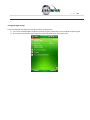
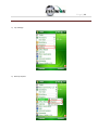
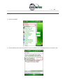
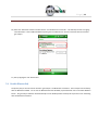
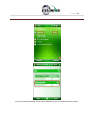
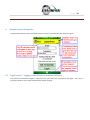
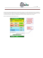
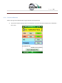
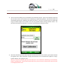
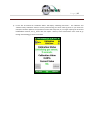
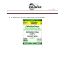
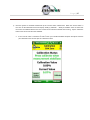
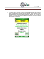
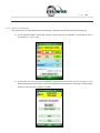
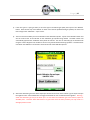
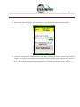
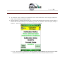
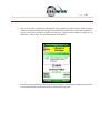
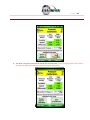
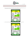
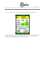
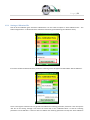
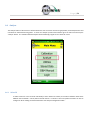
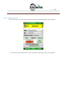
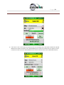
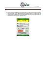
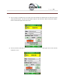
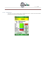
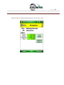
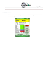
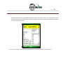
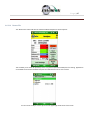
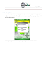
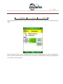
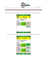
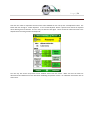
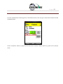
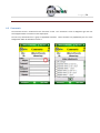
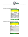
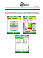
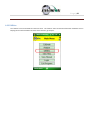
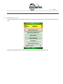
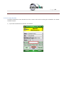
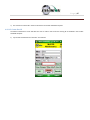
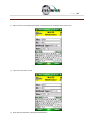
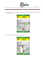
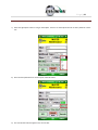
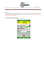
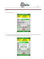
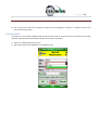
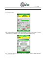
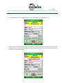
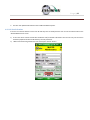
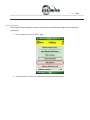
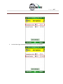
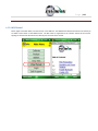
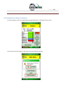
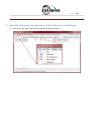
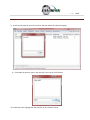
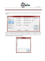
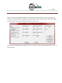
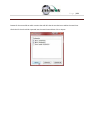
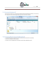
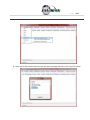
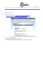
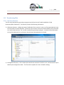
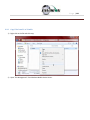
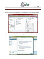
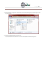
The user must click on the save button to save the changes that have been made to the ID set. The user may
use the “Save As” button to specify a custom name for the file. The program ensures that the file name has
the proper “.xml” extension.
P a g e | 128
7.9 ID set stored location on PC
The ID set file is located in the c:/My Documents/Elkins Earthworks/Configuration directory. The user may
have multiple ID set files referencing multiple sites that the instrument is used on.
7.10 Transferring ID Sets between Trimble and the PC
1) Attach the Trimble to the PC and let the unit synchronize (see section 0 for instructions)
2) Open the Configuration Editor program
3) Select “File” then “Mobile Device” and finally “Copy file from mobile device to PC”.
P a g e | 129
4) Select the file that contains the ID set that you want to manage and click on the “Copy File” button.
P a g e | 130
5) The selected ID set will then populate into the Configuration Editor.
6) Make any desired changes to the selected ID set.
P a g e | 131
7) After all changes have been made the user should send updated ID set back to the handheld.
P a g e | 132
8) Updated ID set will be sent to mobile device and changes to the ID set will be viewable once Elkins
Earthworks® Gas Analyzer program on the handheld has been exited and restarted.
P a g e | 133
7.11 Importing GEM Configuration Files
In order to import a GEM file, the user must find the location of an existing GEM .xml file on their hard drive.
Press the import button and browse to the GEM file location. Note: Information imported into the
Configuration Editor will be limited to well ID names and well configuration settings.
P a g e | 134
7.12 Print Preview
The “Print Preview” button allows the user to view the entire ID set and all of the configurations set for those
wells. The user may print the ID set from this feature.
P a g e | 135
8 Connecting the Trimble Handheld Computer to a PC
8.1 Windows Mobile Device Center
Windows computers utilize Windows Mobile Device Center to connect and synchronize with mobile devices.
Perform the following steps to synchronize files between the PC and Trimble:
1) Connect the Trimble unit to the PC with the provided USB cord
2) The Windows Mobile software will open
P a g e | 136
3) First click on Mobile Device Settings then “Set up your device”.
4) Check the items that you want to synchronize each time you connect to the Trimble. Then click on “Next”.
We recommend not selecting any boxes since this will slow your synchronize time. Do not select the Files
box as that may lead to contamination of the field data.
P a g e | 137
5) Name the Trimble
P a g e | 138
6) The Nomad will then Sync with the PC
P a g e | 139
8.2 Windows XP Machines
8.2.1
Download Active sync
1) Visit the following website: http://www.microsoft.com/windowsmobile/enus/downloads/eulas/eula_activesync45_1033.mspx?ProductID=76
2) Click on Accept and Download
3) Follow the directions for the software installation
4) Connect the Trimble handheld computer by using the provided standard USB cable
P a g e | 140
5) The Synchronizing Wizard will open during the first connection. Click next.
6) Enter the name of what you want to call the Trimble that is being connected
a. Synchronization wizard will now open. Select the tasks that you wish to synchronize each time the
Trimble is connected. We recommend not selecting any boxes since this will slow you synchronize time.
Do not select the Files box as that may lead to contamination of the field data.
P a g e | 141
7) Allow wireless connections option screen. Make sure the check box for “Allow wireless connections” is
unchecked. Click on next.
8) The connection wizard will now store the user’s settings once the “Finish” button is clicked.
P a g e | 142
9) ActiveSync will now open and sync with the Trimble. The Trimble will now perform this function each time
it is connected to the user’s PC.
10) ActiveSync will automatically make a file on the desktop
P a g e | 143
11) Once the Nomad has synchronized, the files in the desktop folder are now exactly what is on the Trimble.
The user may now disconnect the Trimble.
12) By selecting the desktop folder the user can view and modify any of the contents.
P a g e | 144
8.3 Transferring Files
8.3.1 Directory Structure
The files associated with the gas analyzer program may be found on the Trimble handheld at C:\My
Documents\Elkins Earthworks. This directory contains the following 3 directories:
1) Calibration Directory – Where two types of calibration files are stored. A new .csv file is generated each time
the user performs a field calibration. These files may be used to verify that a field calibration was performed
on a certain date and time. The .xml file is used by the gas analyzer program. It contains information about
the last field calibration for each Envision that has been calibrated with the Trimble.
2) Configuration Directory – This is where all the well ID sets are stored. The files are in .xml format and may be
edited by the configuration editor. The file must be copied to the user’s PC before editing.
P a g e | 145
3) Field Data Directory – This is where all the .csv field data files reside. A new file is generated each day and
each month that a measurement is taken. These files may be opened with Excel. If the encryption option is
enabled, .enc encrypted files are also present.
P a g e | 146
8.3.2
Copy Files from PC to Trimble
1) Right click on the file and click copy.
2) Open ”File Management” from Windows Mobile Device Center.
P a g e | 147
P a g e | 148
3) Follow the path shown to the proper folder on the Trimble. Right click in an empty space and click paste.
4) If a file with the same name already exists, then a warning message may appear. If you are sure you want to
replace the file then click on “Copy and Replace”
P a g e | 149
5) The file will now load onto the Trimble.
8.3.3
Copy File from Trimble to PC
If an ID set is modified in the field with the Trimble unit then the user will want to place the modified file back
onto the PC unit for backup and potential modification by the “Configuration Editor” software.
1) Synchronize the Trimble with the PC
2) Open ”File Management” from Windows Mobile Device Center.
P a g e | 150
3) Open the Nomad’s “Configuration” folder which can be found by following the path shown. Right click and
copy the ID set file.
4) Locate the Configuration folder on the user’s PC:
C:\Users\Owner\Documents\Documents on Envision Nomad\Elkins Earthworks\Configuration
P a g e | 151
5) Click paste. If an ID set file with the same name already exists, then a warning message will appear. If you are
sure you want to replace the file then click on “Copy and Replace”
6) The file is now located on the user’s computer.
P a g e | 152
9 Errors and Troubleshooting
9.1 Envision® Error Conditions:
Error conditions from meter are presented by a blinking red “!” next to the connect icon in the header of each screen.
The description of the error will appear in the “Meter Status” screen under error conditions. The following are error
conditions that may be displayed:
1)
“Component Failure -Error #1”
a. Explanation - The battery gauge is displaying erroneous battery data, as a result of a charging chip
failure. This will affect battery cut-offs and accurate monitoring.
b. Solution – Call technical support at Elkins Earthworks® 330-725-7766.
2) “Component Failure -Error #2"
a. Explanation- The charging chip is not shutting off the charging process.
b. Solution - Call technical support at Elkins Earthworks® 330-725-7766.
3) “Component Failure -Error #3"
a. Explanation - The Envision is charging too slowly.
b. Solution - Call technical support at Elkins Earthworks® 330-725-7766.
4) “Component Failure -Error #4"
a. Explanation- The pump, manifold pressure sensor, or either of the two IR sensors have stopped
operating correctly and are not drawing any current.
b. Solution – Power down Envision® unit and reconnect to the Trimble handheld computer. If
this does not correct the problem call technical support at Elkins Earthworks® 330-725-7766.
5)
“Component Failure -Error #5"a. Explanation- Excessive current draw. Any number of parts may have failed due to a short or
component failure. Component failure of pressure sensor
b. Solution – Power down Envision® unit and reconnect to the Trimble handheld computer. If
this does not correct the problem call technical support at Elkins Earthworks® 330-725-7766.
6)
“Component Failure -Error #6”
a. Explanation- One of the pressure sensors is reading out of spec, likely due to an overpressure situation
(blown sensor)
b. Solution – Try restoring the factory calibration on the pressure sensor calibration screen. If
this does not solve the problem then power down Envision® unit and reconnect to the
Trimble handheld computer. If this does not correct the problem call technical support at
Elkins Earthworks® 330-725-7766.
7) “Component Failure -Error #7”
a. Explanation- Low flow condition
b. Solution – Check that the sample train hoses are not pinched. Check inline filters and make
sure that they are clear and free from debris and liquids. If this does not correct the problem
call technical support at Elkins Earthworks® 330-725-7766.
8) “Component Failure -Error #8”
P a g e | 153
a.
Explanation- Oxygen sensor is out of spec. Potentially bad sensor.
b. Solution – Restore factory calibration on O2 sensor and recalibrate. If recalibration does not
solve the error then power down Envision® unit and reconnect to the Trimble handheld
computer. If this does not correct the problem call technical support at Elkins Earthworks®
330-725-7766.
9)
“Low Flow Rate”
a. Explanation- Low Flow from clogged or pinched sample train.
b. Solution – Check that the sample train hoses are not pinched. Check inline filters and make
sure that they are clear and free from debris and liquids. If this does not correct the problem
call technical support at Elkins Earthworks® 330-725-7766.
10) “Over Pressure”
a. Explanation- Pressure applied to pressure sensors are higher than sensors a specified for.
b. Solution – Disconnect hoses from measurement location and recalibrate sensors. Verify that
the pressure on the sample point is within the tolerance of the Envision® gas analyzer. If this
does not correct the problem call technical support at Elkins Earthworks® 330-725-7766.
11) “Battery low. Plug in charger”
a. Explanation- Pressure Low battery on Envision unit
b. Solution – Plug meter in to charge. If this does not correct the problem call technical support
at Elkins Earthworks® 330-725-7766.
12) “Battery level is critically low”
a. Explanation- Battery level is low.
b. Solution – Charge Envision® gas analyzer. If the unit does not charge then call technical
support at Elkins Earthworks® 330-725-7766.
13) “Unit over temperature. Cool unit”
a.
Explanation- Measurement Unit over temperature.
b. Solution – Move the Envision® unit into a cooler environment. If the error does not clear then
call technical support at Elkins Earthworks® 330-725-7766.
9.2 Other error codes
Listed below are additional error messages that may show up during operations:
1) “Unable to connect to selected meter”
a. Explanation- Connection attempt failed during meter selection
b. Solution – Make sure that the Envision® unit is on and the Bluetooth light is blinking before
tapping search on the Trimble handheld computer. Also, verify that the Trimble handheld’s
Bluetooth is turned on. If this does not solve the problem then power down Envision® unit,
close the Elkins Gas Analyzer software on the Trimble and retry to reconnect to the Trimble
handheld computer. If this does not correct the problem call technical support at Elkins
Earthworks® 330-725-7766.
2) “The Bluetooth connection to the meter has been lost”
P a g e | 154
a. Explanation- Bluetooth connection has been disrupted either due to interference or user has walked
out of range from the Envision® gas analyzer.
b. Solution – Walk back within range of the Envision® gas meter and let the Bluetooth attempt
to reconnect. If this does not solve the problem then power down Envision® unit, return the
Elkins Gas Analyzer software to the “Select Meter” screen on the Trimble. Reboot the
Envision® unit and try to connect to the Envision® gas analyzer. If this does not correct the
problem call technical support at Elkins Earthworks® 330-725-7766.
3) “Unable to initialize scanner device”
a. Explanation- The scanner function is not active on the Trimble handheld computer.
b. Solution – Verify that the Trimble unit has a barcode reader. If not the barcode feature will
not be active. If the Trimble has a barcode reader then the user needs to verify that the
correct driver is installed and the application is active. Call technical support at Elkins
Earthworks® 330-725-7766 for help in verifying drivers.
4) “GPS data not valid”
a. Explanation- the GPS function is not active on the Trimble handheld computer or the GPS has not yet
connected with the satellites.
b. Solution – Allow the Trimble unit at least four minutes outside to connect to the satellites. If
this does not solve the problem then verify that the Trimble unit that the user has purchased
has a GPS receiver. If not, the GPS feature will not be active. If the Trimble has a GPS receiver
then the user needs to verify that the GPS is correctly configured as shown in Section 5.5.
Also make sure that that there is no other application using the GPS signal (e.g. SatViewer). If
this does not correct the problem call technical support at Elkins Earthworks® 330-725-7766
for help.
5) “Failed to find GPS/barcode match”
a. Explanation- the GPS function or barcode reader is not active on the Trimble handheld computer.
b. Solution – Verify that the Trimble unit that the user purchased has a GPS receiver. If not the
GPS application will not be active. If the Trimble has a GPS receiver then the user needs to
verify that the GPS is correctly configured as shown in Section 5.5. Also make sure that that
there is no other application using the GPS signal (e.g. SatViewer). If this does not correct the
problem call technical support at Elkins Earthworks® 330-725-7766 for help.
P a g e | 155
10 Envision® Maintenance
10.1 Factory Maintenance
The Envision® gas analyzer should be returned to the factory at a minimum once per year for inspection and
factory calibration.
10.2 Field Maintenance
The Envision® gas monitor has two internal filters. Over time these filters may clog or become fowled and
may need to be changed. In order to change the filters, locate the aluminum door on the back of the
Envision® gas analyzer under the protective black boot.
Remove the aluminum filter door by loosening the screws and lifting the door off of the enclosure. Warning:
do not remove the filter door in dusty or wet atmospheres as the internal components can get damaged.
P a g e | 156
The user may now remove and replace the filters by turning the Luer filter fittings. Make sure the seal is still in
place and re-attach the filter door. Replacement Luer filters may be purchased from Elkins Earthworks®.
P a g e | 157
11 Warranty
11.1 Envision® Warranty
Elkins Earthworks®, LLC warrants its products to be free from defects in workmanship. This warranty shall be fulfilled
by Elkins Earthworks® repairing or replacing its products, as necessary, to cure any such defect, which is reported to
Elkins Earthworks® within 12 months of the ship date. All warranty work will be done at Elkins Earthworks®.
(a) This warranty shall not apply to products which have been abused, altered, misused in application, improperly
maintained or repaired.
(b) This warranty does not apply to components designed to be consumed or destroyed in normal operation.
(c) No product or part shall be returned to Elkins Earthworks® without its prior consent. Any products which Elkins
Earthworks® consents to have returned shall be shipped F.O.B. Elkins Earthworks® factory.
(d) In the event the BUYER delays shipment, the warranty period commences on the date Elkins Earthworks® is
prepared to make shipment.
(e) BUYER shall give Elkins Earthworks® written notice of the defect promptly after discovery.
(f) This warranty is exclusive and is expressly in lieu of any other express or implied warranties.
11.2 Trimble Handheld Warranty
The following wording is from the standard Trimble Warranty – For a full description please refer to the
Trimble Warranty document included in the Trimble packet in the Storm case lid when purchased.
Hardware Warranty. Commencing on the Hardware Extended Limited Warranty Commencement Date and
during the Hardware Extended Limited Warranty Term set forth on the Signature Page the Trimble Navigation
Limited Hardware Products are warranted against defects in material and workmanship. Warranty service will
be provided at a designated Trimble Service Center. Trimble will at its option either repair or replace products
that prove to be defective. If Trimble is unable to replace the products, Trimble will refund the price paid for
this agreement. The Customer shall pay all shipping charges for products returned to Trimble for warranty
service. Trimble shall pay all shipping charges for the return of products to the Customer. These are your sole
remedies, and Trimble’s sole liability, for any breach in this warranty.
Hardware Warranty Exclusions. The above warranty shall not apply to defects resulting from: (1) improper or
inadequate maintenance by you; (2) Purchaser-supplied software or interfacing; (3) unauthorized modification
or misuse; (4) operation outside of the environmental specifications of the product; (5) improper installation,
where applicable; (6) lightning or other electrical discharge; (7) fresh or salt water immersion or spray; (8)
normal wear and tear on consumable parts (for example, and without limitation, batteries).
P a g e | 158
Software/Firmware Extended Limited Warranty. Commencing on the Software/Firmware Extended Limited
Warranty Commencement Date and during the Software/Firmware Extended Limited Warranty Term set forth
on the Signature Page, Trimble Navigation Limited warrants that the Trimble Navigation Software and
Firmware Products will substantially conform to the published specifications provided it is used with the
Trimble products, computer products, and operating system for which it was designed. Trimble also warrants
that the storage media on which Software and Firmware are distributed and the accompanying
documentation are free from defects in materials and workmanship. Such warranty shall not apply in the
event or to the extent that data supplied by you contains errors or is improperly or incorrectly installed.
During the Software/Firmware Extended Limited Warranty period, Trimble will replace defective media or
documentation, or correct substantial program errors at no charge. If Trimble is unable to replace defective
media or documentation, or correct program errors, Trimble will refund the price paid for the Software or
Firmware. These are your sole remedies for any breach in warranty.
Software/Firmware Warranty Exclusions. The above warranty shall not apply to Software and Firmware
products that (1) have been altered or modified in any way without Trimble’s authorization; (2) have problems
resulting from interaction with software, firmware or hardware not supplied or supported by Trimble; (3) have
problems caused by improper or inadequate maintenance by Purchaser.
P a g e | 159
12 Problems and Potential Solutions
12.1 Problems and Potential Solutions for Envision & Trimble
Problem
Nomad will not Connect to the Envision
by Bluetooth
The Elkins Gas Analyzer software will not
turn on
Nomad will not read GPS
The lighting on the Nomad is dull
O2 reading seems high
The screen is dark
CH4 is over 1000%
Potential Solution
-Check the home screen on the Nomad to insure the WLAN is
OFF
-Check the Envision to make sure the blue light is flashing
next to the Bluetooth button
-Check the home screen on the Nomad to insure the
Bluetooth is ON
The synchronizing setting for the Nomad has the Files box is
selected for Nomad to the Computer. Unselect the files box
and remove all your Field Data files from the Nomad.
-Make sure that Sat Viewer is turned off.
-Check the settings on the Nomad to make sure they match
the settings in section 5.5 of this document for GPS
Press the green power button for just a second
-Check your filters and make sure that they are tight
-Change your O’Rings
-Make sure your hoses have no holes
Please adjust your backlight setting to match section 5.3 of
this document. Also you can just hit the power button for a
second.
It is reading CH4 LEL so click the CH4 sign and it will change
If you are experiences an issue that is not listed above, or the solution above did not solve the issue, please
contact Elkins Earthworks® for further troubleshooting.
P a g e | 160
13 Envision® Specifications
Operation Range
Unit
Minimum
Maximum
Envision®
-4° F
122° F
Comments
Heater unit option for low
temperatures
Gas Sensors
Gas
Sensors
Range
CH4
0 - 100%
Infra-red cell
CO2
0 - 100%
Infra-red cell
O2
0 - 22%
Electrochemical
Comments
Gas Sensor Accuracy
Range
CH4
CO2
O2
0-5%
±0.3%
±0.3%
±0.25%
5-30%
±1.0%
±1.0%
±<1% (Max O2 = 22%)
30 - 100%
±<2.0%
±<2.0%
NA
Resolution
0.01%
0.01%
0.01%
T90
<30s
<30s
<13s
P a g e | 161
Pressure Sensors
Range
Static
(-)5 H2O to
5" H2O
(-)130" H2O to
130" H2O
Accuracy
0.1375
+/- 2% of reading
Resolution
0.001
0.01
T90
<1 ms
<10 ms
Accuracy
0.1375
+/- 2% of reading
Resolution
0.001
0.01
T90
<1 ms
<10 ms
Accuracy
NA
+/- 2% of reading
Resolution
NA
0.01
T90
NA
<10 ms
Comments
According to sensor
manufacture specs.
Differential
Available
Pump Specifications
" H2O
-138
Flow (cc/min)
260
Battery Specifications
Battery Life
Battery
Construction
Charge Time
up to 1000 full charge
cycles
NiMH (no memory)
3 hours from
complete discharge
According to sensor
manufacture specs.
P a g e | 162
Battery Life (NiMH)
Temperature (°F)
77
50
32
14
-4
Life (hours)
13.8
13.1
10.5
6.6
2.6
P a g e | 163
14 Contact information
Service and Sales:
865 West Liberty, Suite 220
Medina, Ohio 44256
Phone: 330-725-7766
Fax: 330-725-7799