1
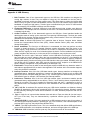
Application Report
SLAA457A – September 2013 – Revised May 2014
Starting a USB Design Using MSP430™ MCUs
Keith Quiring
...................................................................................................... MSP430 Applications
ABSTRACT
This document is a high-level starting point for those wanting to design USB devices with MSP430™
MCUs. It provides an overview of the TI MSP430 hardware and software offerings for USB, as well as
guidance in quickly getting started.
Among the topics covered:
• An overview of the MSP430 hardware USB module
• An introduction to the MSP430 USB Developer's Package
• A hardware reference design for USB devices based on the MSP430 MCU
• A guide to early decisions the developer must make
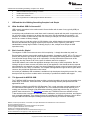
Contents
1
USB and the Art of Making Something Complex Look Simple ........................................................ 2
2
MSP430 USB Silicon ........................................................................................................ 3
3
Software ....................................................................................................................... 6
4
MSP430 USB Hardware Design ......................................................................................... 13
5
MSP430 USB Software Design .......................................................................................... 18
6
Getting Started: Evaluating MSP430 USB .............................................................................. 20
7
More Information ........................................................................................................... 24
Appendix A
USB Glossary ...................................................................................................... 25
List of Figures
1
MSP430 USB Block Diagram .............................................................................................. 4
2
USB System and USB Developers Package Components
3
USB Developers Package: Examples from TI ........................................................................... 8
4
MSP430 USB Descriptor Tool ............................................................................................ 10
5
USB Host Software
6
7
8
9
10
11
12
13
14
15
............................................................
........................................................................................................
Java HID Demo App .......................................................................................................
MSP430 USB API Documentation .......................................................................................
MSP430 Reference Design for USB-Related Pins ....................................................................
Powering the Entire System From the Internal LDO ..................................................................
MSP430 USB Clock Connections ........................................................................................
Example Process for Deciding on a USB Device Class ..............................................................
MSP430F5529 LaunchPad ...............................................................................................
MSP430F5529 Experimenter's Board ...................................................................................
MSP-TS430PN80USB FET Target Board for F552x ..................................................................
FET Tool (MSP-FET430UIF) Emulator ..................................................................................
7
11
11
12
14
15
16
19
21
22
23
23
List of Tables
1
USB-Equipped MSP430 Derivatives ...................................................................................... 3
2
MSP430 Device Test IDs (TIDs) ........................................................................................... 5
SLAA457A – September 2013 – Revised May 2014
Submit Documentation Feedback
Starting a USB Design Using MSP430™ MCUs
Copyright © 2013–2014, Texas Instruments Incorporated
1
USB and the Art of Making Something Complex Look Simple
3
4
5
6
www.ti.com
.......................................................................... 6
Possible XT2 Clock Sources.............................................................................................. 16
Device Class Tradeoffs .................................................................................................... 18
FET Target Boards for USB-Equipped MSP430 Derivatives ......................................................... 23
MSP430 USB Developers Package: Contents
1
USB and the Art of Making Something Complex Look Simple
1.1
What Has Made USB So Successful?
USB is nearly everywhere in the modern world. We are familiar with its ease of use; typically USB just
works. It is reliable.
Its simplicity and predictable user model have made it extremely popular with the public. Its popularity and
low cost have made it ubiquitous. Its ubiquity has even led to uses beyond data communication – for
example, as a means of power delivery: both out of hosts (for example, into coffee warmers) and into
devices as a means of battery charging.
But a lot is going on under the surface of USB. Making a fast, reliable data bus that automates common
behaviors and tolerates hot plugging requires layers of protocol. And it requires a great deal of
standardization among large numbers of industry players; in fact, multiple forces shape the USB
experience today.
1.2
But It Looks So Simple!
The elegance of USB is that users see none of this complexity – it simply does what they need it to.
But developers can have more trouble avoiding this complexity. Compared to UART, SPI, or I2C, layers of
protocol are required to give USB its unique capabilities. This means that sending data over USB takes
more effort than simply writing a byte to an output buffer. On-chip USB modules offset some of this
complexity, but they cannot do all of this; layers of software need to be employed.
Good USB software can insulate the application developer from many of these complexities. But like
icebergs, the tips of these concerns can still be seen by the application. How should the device respond
when attached or not attached to a host? How should software be written to ensure it keeps flowing even
when the host or bus is busy or unreliable? The simplest USB applications might be able to ignore these
concerns, but professional applications often cannot.
An industry of middleware and consultants is available to help developers through this process. But, many
developers still rely on silicon vendors and the community to provide both software and support.
1.3
TI's Approach for MSP430 USB
The TI MSP430 USB Developers Package provides a solution intended to be simple and accessible for a
broad range of customers. At the same time, it maintains the design flexibility that professional USB
applications need.
Development is aided by the MSP430 USB Descriptor Tool, a code generation tool that handles most of
the USB-related customization for your application. The Tool contains contextual help that aids you in
making your decisions. Example code and detailed reference guides help point the way. If you have a
problem these cannot solve, TI's E2E Forum and other non-TI MSP430 forums are available to help.
TI also welcomes the ecosystem of USB consultants, middleware, and community solutions, and supports
their continued contribution. They enlarge the base of possibilities for MSP430 customers, both for those
using the MSP430 USB Developers Package and for those preferring to outsource USB design.
MSP430, Code Composer Studio, LaunchPad, Launchpad BoosterPack are trademarks of Texas Instruments.
OS X is a trademark of Apple Inc.
IAR Embedded Workbench is a registered trademark of IAR Systems.
Linux is a registered trademark of Linus Torvalds.
Windows is a trademark of Microsoft Inc.
CERALOCK is a registered trademark of Murata Manufacturing Co., Ltd.
All other trademarks are the property of their respective owners.
2
Starting a USB Design Using MSP430™ MCUs
SLAA457A – September 2013 – Revised May 2014
Submit Documentation Feedback
Copyright © 2013–2014, Texas Instruments Incorporated
MSP430 USB Silicon
www.ti.com
2
MSP430 USB Silicon
MSP430 MCUs include an on-chip USB module on several subfamilies. Each family's module is exactly
the same, and each is compatible with the MSP430 USB Developers Package (MSP430USBDEVPACK).
Although bitbanging USB is possible, it cannot be done at full speed, and it is likely to consume much of
the processor's capacity. Most USB applications tend to use the on-chip USB module.
2.1
How MSP430 Devices are Documented
The MSP430 device documentation is structured differently than some of our competitors. For any given
MSP430 device derivative, the documentation is divided into two locations:
• The family user's guide: Contains all of the architectural information for the family. For example, it
contains register sets and block diagrams of all the peripheral modules. All USB-equipped MSP430
devices are described in the MSP430x5xx and MSP430x6xx Family User's Guide (SLAU208).
• The data sheet: Contains all of the parametrics and anything specific to this particular derivative.
This method reduces the number of pages the developer needs to download and read in order to
comprehend the device. All device documentation is found in the combination of these two documents.
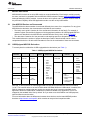
2.2
USB-Equipped MSP430 Derivatives
TI currently has four subfamilies of USB-equipped device derivatives (see Table 1).
Table 1. USB-Equipped MSP430 Derivatives
MSP430
Derivative
F550x, F5510
F551x, F552x
Flash (bytes) RAM (bytes)
8K-32K
32K-256K
16-Bit
Timers
Common
Peripherals
4K(+2K)
4
128K-256K
16K(+2K)
F565x, F665x
384K-512K
32K64K(+2K)
Additional
Features
•
•
•
•
•
•
•
•
•
•
USB
WDT
RTC
DMA (3-6)
MPY32
Comp_B
UART
SPI
I2C
PMM
(BOR, SVS,
SVM, LDO)
Packages
• 48RGZ
• 48PT
• 64RGC
10-bit SAR
4K-8K(+2K)
F563x, F663x
ADC
•
•
•
•
12-bit SAR
• EDI
• DAC12
• Backup battery
switch
• LCD (on F663x
and F665x)
80PN
64RGC
80ZQE
64YFD
(chipscale
DSBGA)
• 100PZ
• 113ZQW
Note that TI documentation for USB-equipped MSP430 derivatives expresses the amount of RAM as
"n+2K". The extra 2K refers to an area of RAM called USB RAM. When the USB module is enabled, this
RAM is mapped into registers that are used by the module and, thus, becomes unavailable to the
application. When the USB module is disabled, this RAM is available to the application, but it is not
mapped by the standard linker files by default. So if you want to use this RAM for non-USB purposes,
special measures must be taken.
For more information about the differences between these devices, see the latest MSP430 product
brochure at http://www.ti.com/msp430, which contains an easy-to-read comparison table.
SLAA457A – September 2013 – Revised May 2014
Submit Documentation Feedback
Starting a USB Design Using MSP430™ MCUs
Copyright © 2013–2014, Texas Instruments Incorporated
3
MSP430 USB Silicon
2.3
www.ti.com
MSP430 USB Module
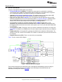
Features of the MSP430 USB module are as follows:
• Full-speed USB device (12 Mbps). Full-speed is a great match for a 16-bit MCU. It facilitates
communication with a USB host, with simplicity and low system cost. The module does not perform
low- or high-speed transfers; it also does not function as a USB host controller.
• Supports control, interrupt, and bulk transfers. This enables support of the most popular USB
device classes. (Streaming audio using isochronous transfers is not supported.)
• Eight input and eight output endpoints. The more endpoints that are supported, the more USB
interfaces (logical devices) that can be implemented within a composite USB device. MSP430 MCUs
have enough endpoints for as many as seven interfaces in composite (depending on the ones
chosen), which is more than enough for the vast majority of USB applications.
• An integrated 3.3-V LDO, for operation directly from 5-V VBUS from the host. In some
applications, this eliminates the need for an external LDO, because in addition to sourcing the MCU,
the integrated LDO can be used to source the entire system, up to 12 mA. (See the device data sheet
for parameters).
• An integrated D+ pullup. This pullup is the way in which a USB device tells the host it is ready to be
enumerated. In contrast, some USB devices from other vendors require external circuitry to enable the
pullup.
• Programmable PLL. An integrated PLL generates the 48-MHz clock needed for USB operation. The
reference for this PLL comes from the MCU's XT2 oscillator. A wide variety of sources can be used for
the reference.
• Integrated transceiver (PHY). There is no need to buy one separately.
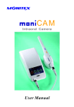
Figure 1 shows a system block diagram.
Figure 1. MSP430 USB Block Diagram
Parts of this block diagram are described as part of the MSP430 USB hardware reference design in
Section 5. The ultimate reference for the module is the USB chapter of the MSP430x5xx and
MSP430x6xx Family User's Guide (SLAU208).
4
Starting a USB Design Using MSP430™ MCUs
SLAA457A – September 2013 – Revised May 2014
Submit Documentation Feedback
Copyright © 2013–2014, Texas Instruments Incorporated
MSP430 USB Silicon
www.ti.com
2.4
USB Certification of the Silicon
To maintain a consistent user experience, it is important that USB devices adhere to compliance
standards. Much of this compliance is driven by the USB silicon and software. The MSP430 device
derivatives, running the USB API, have passed USB certification testing for all of the device classes that
they support. All certification was performed at MCCI, a test house approved by the USB Implementers
Forum (USB-IF).
An output of the USB certification process is a test ID, or TID. Table 2 shows the TIDs for all current
MSP430 silicon.
Table 2. MSP430 Device Test IDs (TIDs)
MSP430 Derivative
Package
TID
PT, RGC, RGZ (QFP, QFN)
40000973
ZQE (BGA)
40001139
MSP430F550x, MSP430F5510
PT, RGC, RGZ (QFP, QFN)
(Note: F5504 in RGZ is not included in this TID; see the next entry)
40001138
MSP430F5504
RGZ (QFN)
41001138
MSP430F552x
MSP430F563x, MSP430F663x
MSP430F565x, MSP430F665x
PZ (QFP)
40001250
ZQW (BGA)
40001442
PZ (QFP, QFN)
40001444
ZQW (BGA)
40001443
All MSP430 devices were certified under a vendor ID (VID) unique to the MSP430 MCU (0x2047),
separate from TI's main VID (0x0451).
SLAA457A – September 2013 – Revised May 2014
Submit Documentation Feedback
Starting a USB Design Using MSP430™ MCUs
Copyright © 2013–2014, Texas Instruments Incorporated
5
Software
www.ti.com
3
Software
3.1
USB Developers Package: Overview
TI provides its MSP430 USB software offering inside the MSP430 USB Developers Package.
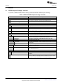
Table 3. MSP430 USB Developers Package: Contents
Item
Description
Host USB Software
Java HID Demo App
Host-side example for implementing HID. It complements the HID-Datapipe
API, simplifying creation of a general-purpose USB HID device.
Python USB Firmware Upgrader
Python-based host-side USB firmware update solution.
MSP430 USB Software
Documentation
API Functional Reference
Doxygen-generated function reference for all the USB API calls
Examples Guide
A guide for the person evaluating the USB API, using the examples
MSP430 USB API Programmer's Guide
A detailed reference for someone that's developing a USB device using the
MSP430 USB Developer's Package.
Release Notes HTML file
Contains anything unique to a particular revision, including bug fixes,
benchmarks, compiler dependencies, and migration information.
MSP430 USB API
API software library for implementing USB devices
Examples
emptyUsbProject
A project containing only a main.c populated with a suggested main loop
framework. The framework is commented with instructions.
CDC Examples
Examples for implementing virtual COM ports using the CDC class.
HID Examples
Examples using the HID class
HID-Datapipe
Examples of HID-Datapipe, a means of UART-style data exchange based on
the HID class.
HID-Traditional
Examples of ordinary HID interfaces, like mice and keyboards
MSC Examples
Examples for implementing mass storage devices, like SD card and
emulated on-chip flash drives.
Composite Examples
Examples of composite USB devices; that is, devices comprising more than
one of the interfaces above
SYS/BIOS Examples
Examples showing us of the USB API with TI's SYS/BIOS RTOS
driverlib (driver library)
Contains the standard MSP430 driverlib. It is referenced by all the examples.
USB_API
These are the actual USB API code files. It is referenced by all the
examples.
MSP430 USB Descriptor Tool
6
Automatically generates reliable descriptors for any combination of USB
interfaces. It saves the developer's time and reduces the chance for errors.
Using this tool is part of the standard recommended design flow.
Starting a USB Design Using MSP430™ MCUs
SLAA457A – September 2013 – Revised May 2014
Submit Documentation Feedback
Copyright © 2013–2014, Texas Instruments Incorporated
Software
www.ti.com
If your application will only use USB for updating the MSP430 firmware, you can jump to Section 3.6. Most
of the software components in the package, about to be described, apply to applications using USB as
part of their main function.
USB Host: Windows,
Linux, Mac, Other
Your Host Application
x
x
x
x
x
x
x
x
USB Host
Virtual
COM Port
PC, Mobile, etc.
Storage
Volume
HID
Interface
MSP430 USB
Descriptor Tool
MSP430-Based
USB Device
CDC
Interface
Mass Storage
Interface
HID
Interface
Generates your
USB interfaces...
Your MSP430 Application
MSP430's USB API
MSP430-Based
USB Device
API Functional
Reference
Functional reference
for API calls
USB API
3URJUDPPHU¶V
Guide
Describes the API, Desc
Tool, and design decisions
Software
Documentation
Provided by TI
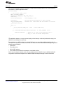
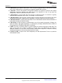
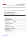
Figure 2. USB System and USB Developers Package Components
The items marked with purple text are provided by TI and correspond with items in Table 3.
The Descriptor Tool generates the USB interfaces you need. You then write an MSP430 application that
communicates with the host through these interfaces.
On the host, you can either write an application or, perhaps, use an existing one. In some cases for
example, an existing COM port or storage-based application might serve your purposes.
Examples are very useful during development. On the MSP430 MCU side, TI provides more than 25
examples of USB applications in the developers package.
On the host side, COM ports and storage are very common, and large amounts of information about these
are found online. In contrast, HID is not as common. For that reason, TI provides the Java HID Demo App
as an example and as a utility.
SLAA457A – September 2013 – Revised May 2014
Submit Documentation Feedback
Starting a USB Design Using MSP430™ MCUs
Copyright © 2013–2014, Texas Instruments Incorporated
7
Software
www.ti.com
USB Host: Windows,
Linux, Mac, Other
HID Demo App (example)
HID Demo Guide
Virtual
COM Port
Storage
Volume
HID
Interface
MSP430-Based
USB Device
CDC
Interface
Mass Storage
Interface
HID
Interface
Examples Guide
25+ USB Examples
MSP430's USB API
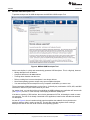
Figure 3. USB Developers Package: Examples from TI
The red-circled examples help get you started in your development. Each is supported by documentation.
All these items are in the MSP430 USB Developers Package, and described further below.
3.2
USB API Stacks: Features
The API is the foundation of the MSP430 USB Developers Package. It supports three of the most
common USB device classes:
• Communications Device Class (CDC): (ACM class) Results in a virtual COM port on the host
• Human Interface Device class (HID): The MSP430 USB Developers Package defines four subtypes:
– Datapipe (an unformatted general-purpose interface resembling CDC)
– Mouse
– Keyboard
– Custom
• Mass Storage Class (MSC): When the host sees an MSC interface, it begins mounting a storage
volume from it.
These classes provide a good selection for general-purpose use. See Section 5.1 for a discussion of how
to choose your interface.
Features of the API include:
• Small peripheral footprint (only the USB module and XT2 oscillator)
• Small memory footprint
• Can use either the DMA or CPU to move data
• Provided as source code
• BSD-licensed, providing maximum flexibility
8
Starting a USB Design Using MSP430™ MCUs
SLAA457A – September 2013 – Revised May 2014
Submit Documentation Feedback
Copyright © 2013–2014, Texas Instruments Incorporated
Software
www.ti.com
CDC and HID-Datapipe provide the developer a simple data exchange interface. As a brief example of
this interface, a simple application follows.
VOID main(VOID)
{
// Init clocks, power, ports
WDT_A_hold(WDT_A_BASE);
PMM_setVCore(PMM_BASE, PMM_CORE_LEVEL_2);
initPorts();
initClocks(8000000);
// CPU frequency, in Hz
initTimer();
USB_setup(TRUE,TRUE);
__enable_interrupt();
// Set up one-second intervals to wake from LPM0
// USB API call; initializes USB and connects to the host
while (1)
{
__bis_SR_register(LPM0_bits + GIE); // Enter LPM0 sleep
if (cdcSendDataInBackground(helloWorldStr, 12, CDC0_INTFNUM, 1000))
{
handleFailedSend(); // Might fail if cable is disconnected, bus is
// busy, or host has become unresponsive
}
}
}
This application wakes up once per second (using a timer interrupt, not shown) and sends a string over
USB to a virtual COM port on the host.
To send data over a CDC interface (to a virtual COM port), you can simply build the interface with the
Descriptor Tool, prepare your data, and call the API construct function cdcSendDataInBackground(), which
accepts these parameters:
• Data buffer
• The buffer's size
• Which CDC interface
• The number of retries before the attempt is considered a failure.
This is only one simple example; much more is possible with the USB API. See the MSP430 USB API
Programmer's Guide and examples in the MSP430 USB Developers Package for more information.
SLAA457A – September 2013 – Revised May 2014
Submit Documentation Feedback
Starting a USB Design Using MSP430™ MCUs
Copyright © 2013–2014, Texas Instruments Incorporated
9
Software
3.3
www.ti.com
MSP430 USB Descriptor Tool
TI provides a unique tool for USB development: the MSP430 USB Descriptor Tool.
Figure 4. MSP430 USB Descriptor Tool
As
•
•
•
•
•
•
the name implies, it quickly and automatically generates USB descriptors. This is a big help, because:
Writing descriptors can be tedious.
Composite devices are far more tedious.
Tracking down mistakes can take time.
Failure resulting from incorrect descriptors is not always obvious.
Not all host operating systems accept every spec-compliant descriptor.
You cannot always find an example for every composite combination you want to use.
The tool generates reliable descriptors, on the first try, for literally any combination of CDC, HID, and MSC
interfaces. It does this in just a few minutes of your time.
On another level, you can think of the tool as building the USB interfaces your application will interact with
(see Figure 2). As such, it is the first step in developing an MSP430 USB project.
If the device contains a CDC interface, the tool also generates an INF file, eliminating the need to create
one manually. The INF file is already customized to the application, based on the data that was entered
for descriptors.
As seen in Figure 4, the tool contains a help pane that explains the tradeoffs of every decision the
engineer needs to make in setting up the API. The tool also warns the engineer when creating a
descriptor set that will not work on all common host operating systems.
10
Starting a USB Design Using MSP430™ MCUs
SLAA457A – September 2013 – Revised May 2014
Submit Documentation Feedback
Copyright © 2013–2014, Texas Instruments Incorporated
Software
www.ti.com
3.4
Host Software, and the Java HID Demo App
The kernel-level host drivers for CDC, HID, and MSC are already present within the common host
operating systems (Windows™, Mac OS X™, and Linux®). But the developer must identify or create an
application on the host that interfaces with the USB device.
x
x
x
x
User Applications
?
x
x
Host OS
x
CDC
HID
MSC
Driver Driver Driver
x
Windows
Linux
MacOS
USB Host
PC, Mobile, etc.
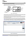
Figure 5. USB Host Software
Writing host software for CDC and MSC interfaces is very straightforward, because they present interfaces
to the host that are very commonly understood: virtual COM ports and storage volumes. These interfaces
are not specific to USB, and resources on writing code for them are very easy to find.
HID interfaces are different, because they are more specific to USB. Some HID interfaces are actually PC
peripherals that the host operating system itself interacts with it directly, like a mouse or keyboard. These
do not need additional host software.
But sometimes HID interfaces are beneficial for general communication (like the MSP430 HID-Datapipe
interface). Writing custom applications to talk with an HID interface can be slightly more complicated than
interfacing with a COM port or storage volume. For this reason, TI provides the Java HID Demo App (see
Figure 6). This application is provided as both a source code example and an executable that serves as a
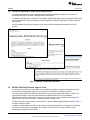
utility. Because it is written in Java, it is meant to be extendable across multiple host platforms.
Figure 6. Java HID Demo App
SLAA457A – September 2013 – Revised May 2014
Submit Documentation Feedback
Starting a USB Design Using MSP430™ MCUs
Copyright © 2013–2014, Texas Instruments Incorporated
11
Software
3.5
www.ti.com
USB API Programmer's Guide and Examples Guide
A complete programmer's guide is included in the developers package to answer your questions. It
describes every aspect of writing USB applications with the API.
A separate examples guide is provided. The MSP430 USB API Examples Guide is intended for the person
only evaluating and running the examples, while the MSP430 USB API Programmer's Guide focuses on
development.
An HTML-based API reference document set is also provided for detailed information on each API
function.
Figure 7. MSP430 USB API Documentation
3.6
MSP430 USB Field Firmware Upgrade Tools
A common use of USB is to enable end users to update the firmware. Among the advantages of this is
that bug fixes can be pushed proactively, increasing user satisfaction and reducing returns.
The vast majority of MSP430 derivative devices have an on-chip bootstrap loader (BSL). The BSL is a
program that resides in a special protected location in MSP430 flash memory and facilitates
communication with an external host. Like tools with JTAG access, it can read and write to the MCU's
flash memory. But unlike JTAG tools, it cannot be used to emulate code.
The BSL interface is often a UART, or sometimes I2C. On the USB-equipped derivatives listed in Table 1,
the BSL's interface is USB.
In addition to field updates, the BSL can be used for production programming. It also plays an important
role when JTAG access is not available. For example, it can be used to recover the device when
something has corrupted internal flash.
12
Starting a USB Design Using MSP430™ MCUs
SLAA457A – September 2013 – Revised May 2014
Submit Documentation Feedback
Copyright © 2013–2014, Texas Instruments Incorporated
MSP430 USB Hardware Design
www.ti.com
Because of potential use in the field, the BSL is password-protected to prevent unwanted access to
proprietary application software.
The BSL must be invoked, meaning that CPU execution must be transferred to it. On the USB BSL, this
can happen in one of three ways:
• The application software in main flash can jump into it
• A BOR reset while the reset vector is blank
• A BOR reset while the PUR pin is held high externally – perhaps by way of a pushbutton switch
Field applications of the USB BSL are likely to use the first method, because a main application is already
in control of the device. In this way, the developer can design a simple end user experience for the
update. However, if main software becomes corrupted, this method might not work.
The second method is used during production of a device based on the MSP430 MCU, because the reset
vector is blank when it leaves TI's factory; you can simply assemble the board and attach the device to a
USB host, and it will enumerate under BSL control. This method also plays an important role in recovering
from interrupted BSL sessions, because the reset vector is left blank throughout the update process.
The third method is the most reliable but often requires the additional cost of a pushbutton.
The BSL is designed to automatically recognize four frequencies applied to XT2:
• 4 MHz
• 8 MHz
• 12 MHz
• 24 MHz
If using BSL for production programming, you must use one of these four frequencies. If using BSL after a
JTAG session has been performed, you can use that JTAG session to program a modified version of the
BSL that can recognize your frequency.
All of this is described in the application note Field Firmware Updates on MSP430 MCUs (SLAA452).
Supporting this application note, the MSP430 USB Developers Package includes the Python-based
Firmware Updater application. This application is built on the open source package python-msp430-tools.
It can be used from a command line, or a GUI can be built on top of it.
4
MSP430 USB Hardware Design
4.1
TI Reference Design for USB Interface
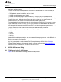
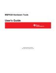
Figure 8 shows a detailed reference design, and commentary follows it.
SLAA457A – September 2013 – Revised May 2014
Submit Documentation Feedback
Starting a USB Design Using MSP430™ MCUs
Copyright © 2013–2014, Texas Instruments Incorporated
13
MSP430 USB Hardware Design
www.ti.com
If internal LDO is
enabled (default),
VUSB sources out.
Can also be sourced in.
3.3V +/-9%
VUSB
V18
System
220nF
>6V
220nF
>6V
Position
caps close to
VUSB/V18/VSSU
VSSU
5V
VBUS
VUSB
4.7uF
>10V
100, ±5%
Supports hardwareinvoked bootstrap loader
PUR
1.4k, ±1%
27, ±5%
SHIELD
VBUS
D+
DGND
D+
D-
27, ±5%
1M, ±5%
IO1
IO2
GND
VCC
VBUS
10pF
>6V, ±10%
10pF
>6V, ±10%
TPD2E001
ESD Suppressor
0.1uF
External clock
source >1.5MHz
XT2IN
>4MHz
XT2OUT
MSP430
Choose crystal, resonator,
or an external clock
source
Figure 8. MSP430 Reference Design for USB-Related Pins
14
Starting a USB Design Using MSP430™ MCUs
SLAA457A – September 2013 – Revised May 2014
Submit Documentation Feedback
Copyright © 2013–2014, Texas Instruments Incorporated
MSP430 USB Hardware Design
www.ti.com
The following sections comment on this reference design. They are not intended as a comprehensive
guide to good USB design, but rather they address issues specific to MSP430 MCUs. Many good industry
resources exist for USB layout and shielding recommendations.
4.2
Selecting a Power Configuration
The USB host provides 5-V power over the USB cable, called VBUS. A device can draw some or all of its
power from VBUS. For devices that will be permanently "tethered" to the host, this can eliminate the need
for a local power source.
For battery-powered devices – those that must be able to operate when detached from the host – VBUS
power is still very valuable, because USB attachment can keep a device active for long periods of time,
increasing the power requirements beyond what would be required otherwise. These devices can switch
their power to VBUS while attached, to avoid draining the battery.
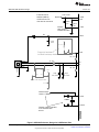
USB-equipped MSP430 devices have an integrated LDO that reduces 5-V VBUS to a nominal 3.3 V. This
rail can be used to source:
• the USB module
• the MSP430 DVCC power rail (most MSP430 devices use a 1.8-V to 3.6-V DVCC rail)
• the rest of the board
The connection between the LDO and the USB module is internal. The rail is also made available on the
VUSB pin. There is no internal connection between VUSB and DVCC; they are isolated from each other.
This preserves flexibility for the engineer designer to arrange power in a way that is best for a given
application.
The maximum current that can be drawn out of the VUSB pin, for use on DVCC and elsewhere on the
board, is approximately 12 mA (see the device data sheet for specific parametric values). In some
applications, this is sufficient for the entire system and can eliminate the need for any other LDO.
System
3.3V
DVCC
VUSB
+5V VBUS
VBUS
3.3V
LDO
1.8V
LDO
Transceiver & PLL
PMM
Transceiver
Other
USB Module MSP430
Figure 9. Powering the Entire System From the Internal LDO
Many other power arrangements are possible. For example:
• VUSB might be used only for USB, using a different source for DVCC or the rest of the system. If more
than 12 mA is needed, this is a convenient approach.
• The internal 3.3-V LDO might be disabled, and 3.3 V can be driven into VUSB from an external source.
Choosing an external LDO with ultralow quiescent current can reduce current drain on VBUS during
USB suspend.
• A switched approach can be employed: source DVCC and the system from a battery when USB is not
attached but, upon attachment to a host, switch them to VBUS and VUSB
• USB battery charging can be employed, using a device such as TI's BQ24030.
VSSU is the ground for the USB module, including the transceiver and LDOs. The capacitors on VUSB
and V18 should be kept as close as possible to VSSU, and VSSU should be tied to board ground.
SLAA457A – September 2013 – Revised May 2014
Submit Documentation Feedback
Starting a USB Design Using MSP430™ MCUs
Copyright © 2013–2014, Texas Instruments Incorporated
15
MSP430 USB Hardware Design
www.ti.com
For developers who want to source into VUSB from an external source, the Descriptor Tool includes a
checkbox for this. If checked, it causes the USB API to keep the internal 3.3-V LDO disabled. However,
you must still attach the VBUS signal from the USB cable to the VBUS pin, in the manner shown. The
presence of 5 V on VBUS is the way in which USB devices determine whether a host is available;
therefore, software needs this signal.
4.3
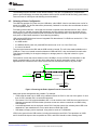
Selecting a Clock Configuration
The MSP430 USB module internally uses a 48-MHz clock, which is generated from an integrated PLL.
The PLL needs a precise reference clock, which comes from the XT2 oscillator.
USB
General
MSP430
F5xx UCS Module
USB Module
VLO
REFO
48 MHz
PLL
XIN
XOUT
XT2
XT1
MCLK
SMCLK
ACLK
Apply a crystal, or source a
clock signal into XIN
Figure 10. MSP430 USB Clock Connections
4.3.1
Choosing a Source
The biggest consideration is precision. The USB specification requires the clock have a tolerance of
±2500 ppm. Sources that do not meet this may actually work under some conditions, perhaps with
compromised performance. But choosing a source that meets the requirement will provide consistent best
performance and ensure USB compliance.
With this in mind, the engineer has three basic choices to source the PLL reference, shown in Table 4.
Table 4. Possible XT2 Clock Sources
Source
External clock source
(put XT2 in "bypass"
mode)
Frequency
Range
1.5-32 MHz
When to Use?
If a clock that is always available during USB communication is present on the board, this
is often the best choice, because it saves the cost of a crystal. However, if the USB BSL
will be used, it must be modified for bypass mode, and this might affect its use for
programming at production – see Section 3.6.
Crystal
4-32 MHz
Crystals provide great flexibility and excellent precision.
Ceramic resonator
4-32 MHz
Many resonators do not achieve the required tolerance. However, a few (for example,
some parts within the Murata CERALOCK® family) do. These might be less expensive
than crystals.
NOTE: Always verify parameters against the most recent device data sheet.
See the Unified Clock System (UCS) chapter of the MSP430x5xx and MSP430x6xx Family User's Guide
(SLAU208) for information on sourcing a clock into XT2's XIN pin in bypass mode.
The source must also not contain excessive jitter that would interfere with the PLL's ability to lock to it.
(For this reason, the MSP430 FLL output cannot be used as a reference for the PLL.) Whether using a
crystal or bypass mode, be sure the frequency is compatible with the options available for the
programmable PLL (see the MSP430x5xx and MSP430x6xx Family User's Guide).
16
Starting a USB Design Using MSP430™ MCUs
SLAA457A – September 2013 – Revised May 2014
Submit Documentation Feedback
Copyright © 2013–2014, Texas Instruments Incorporated
MSP430 USB Hardware Design
www.ti.com
If using a crystal, the load capacitors should be properly chosen, according to the crystal's specification.
This is especially true if the oscillator will be shut down during USB suspend to save power consumption,
in which case improper capacitor selection could result in a slow response to USB resume. Improper
capacitor values could cause crystal startup to take longer than it should, and the device has a total of 10
ms to become USB-ready when the host performs a USB resume on the device. If the oscillator had been
disabled during suspend for power savings, then its re-enabling is part of this 10-ms budget. (A properlytuned oscillator will easily meet the requirements.)
Note that XT2 derives its power from the DVCC pin, rather from the internal USB LDO. Also note that XT2
consumes approximately 200-400 µA, depending on the frequency. (See the device data sheet for actual
values.)
4.3.2
Choosing a Frequency
A wide range of frequencies is possible, because the USB PLL has a very flexible programmable input
divider. Each MSP430 header file contains predefined constants for 43 possible frequencies, and many
more are possible. (The pre-defined ones are of the format USBPLL_SETCLK_xx_yy, where xx_yy is
frequency-specific.)
As shown in Section 4.3.1, each clock source is subject to a frequency range.
There are two considerations in frequency selection:
• Lower-frequency crystals or resonators consume less power than higher ones. (See the device data
sheet power consumption values for XT2.)
• If using the USB BSL for factory programming of the MSP430 device, only 4, 8, 12, and 24 MHz are
auto-recognized by the BSL. See Section 3.6.
USB-equipped MSP430 boards from TI usually use a 4-MHz ceramic resonator that meets USB precision
requirements. Being the lowest-frequency crystal possible, these have the advantage of minimizing power
consumption. 4 MHz is also auto-detected by the on-chip BSL.
4.4
Other Reference Design Commentary
The circuitry within the dashed rectangle in Figure 8 is required only if the bootstrap loader (BSL) is to be
invoked using a pushbutton switch, for performing firmware updates through USB. PUR is normally an
output, but in the moments following a BOR reset, it is an input that determines whether or not the BSL
will be invoked. This pushbutton is only one way to invoke the BSL; see Section 3.6 for more information.
The weak pulldown resistor on PUR ensures that the PUR pin stays low if the pushbutton is not pressed.
(It is weak enough to not disrupt D+ during USB operation.) This pulldown should never be eliminated, as
doing so might result in unintended invocation of the BSL.
The pullup resistor is specified as 1.4k. Those with USB experience are aware that the pullup value
specified in the USB specification (parameter RPU) is 1.5k. The reason for this difference is that the
MSP430 device's PUR pin itself contributes approximately 100 Ω (shown as parameter RPUR in the
device data sheet). The sum of this amount and the external 1.4k resistor produces the complete value
RPU. To be absolutely compliant, a 1% resistor is needed. This is because the sum of the errors on RPUR
and a 5% resistor slightly exceed the 5% allowed by the USB specification on RPU. Practically speaking,
however, there is no problem using 1.4k ± 5%.
At 12 MHz, full-speed USB usually is not highly sensitive to transmission line characteristics, but it is
recommended to keep D+ and D- reasonably short.
A USB port can represent an ESD vulnerability, because it extends a conductive path to the outside of the
enclosure, which the user frequently touches. Under these conditions, the protection integrated into most
ICs is not enough to withstand the levels of discharge it might experience. Therefore, a dedicated ESD
suppressor is recommended, such as the TPD2E001 shown. It is important to follow all the design
recommendations in the TPD2E001's data sheet.
The diode on VBUS is placed there to ensure compliance with the USB 2.0 specification's requirement
that the device never source current toward the host over VBUS.
SLAA457A – September 2013 – Revised May 2014
Submit Documentation Feedback
Starting a USB Design Using MSP430™ MCUs
Copyright © 2013–2014, Texas Instruments Incorporated
17
MSP430 USB Software Design
5
www.ti.com
MSP430 USB Software Design
Most of the MSP430 USB software documentation is located in the USB API Programmer's Guide, located
in the USB Developers Package. Therefore, this section is only an introduction.
5.1
How to Choose a USB Device Class
Tradeoffs between the three device classes are shown in Table 5. (Plain text indicates advantages or
neutral comments, and italic text indicates possible disadvantages.)
Table 5. Device Class Tradeoffs
Characteristic
HID
(Human Interface Device Class)
MSC
(Mass Storage Class)
The interface
generated on
the host
• Virtual COM port
• A human interface device
Industry
expertise for this
interface
• COM ports are common in the
industry; widely-supported and
well-understood
• Unlike COM ports or storage
volumes, HID interfaces are
somewhat USB-specific, and
less known in the industry
Installation on
the host
• Windows PCs must undergo a
device installation process that
requires end user interaction. (1)
• Admin rights on this Windows
PC are required
• Despite the actual binary files
already existing in Windows,
the user must supply an INF
file
• Loads silently in most
operating systems – simply
begins working.
• No driver files required
• Loads silently in most
operating systems – simply
begins working.
• No driver files required
How the end
user interacts
with it
• An application on the host that
interfaces with COM ports
• The application might be
custom, or any existing
application that uses COM
ports
• A custom application on the
host that interfaces with HID
devices
• The device mounts a storage
volume onto the system;
applications read and write
files on the volume.
• The application might be
custom, or any application that
reads or writes files
Driver
certification
needs
• Unless the INF file is WHQL
certified (signed), Windows will
report that the driver is
'uncertified'. (2)
• No 'uncertified' message is
generated
• No 'uncertified' message is
generated
Code footprint
and complexity
• Small code footprint (4-6K)
• Simple architecture
• Small code footprint (4-6K)
• Simple architecture
• Larger code footprint (8-15K)
• Requires a file system,
increasing cost, size, and
complexity.
Throughput
• Fast (hundreds of KB/sec)
• Uses bulk USB transfers.
• Slower (64 KB/sec)
• Uses interrupt USB transfers.
• Fast (hundreds of KB/sec)
• Uses bulk USB transfers.
Good for pointto-point
communication
between host
and device
• Yes
• Yes
• No
Good for bulk
data transfer
• Yes
• No
• Yes
(1)
(2)
18
CDC
(Communications Device Class)
• Storage volume
Storage volumes are common in the
industry; widely-supported and wellunderstood
This is the process that occurs the first time the device is attached to the host. In Windows, this process may begin with a
"Found New Hardware" dialog box. The user must locate the INF file provided by the OEM.
WHQL certification refers to Microsoft's Windows Hardware Quality Labs. See http://www.microsoft.com/whdc/winlogo.
Starting a USB Design Using MSP430™ MCUs
SLAA457A – September 2013 – Revised May 2014
Submit Documentation Feedback
Copyright © 2013–2014, Texas Instruments Incorporated
MSP430 USB Software Design
www.ti.com
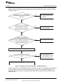
Sometimes the choice of device class is clear. In other cases, the application can be considered general
purpose, giving the developer options. Although there are many ways to approach this decision, one way
is shown in Figure 11.
Does the device need to be backwardcompatibility with an existing host PC
application?
Use the device class for which
the original host application
was designed.
YES
NO
Is the device a mouse, keyboard,
or other peripheral in which the
host operating system recognizes
and interacts with the device?
YES
Use HID. (In MSP430's API,
µ^,/-d]]}vo_)
NO
Does the device type
have a strong association with a
particular class? (PHD class for medical; CCID
class for smart card; Imaging
class for cameras; etc.)
YES
Use the expected device class.
YES
Use HID. (In MSP430's API,
µ^,/-]_, to create
an unformatted datastream.)
NO
dZo]]}vv}v]^Pvoµ}_.
Is the required bandwidth under 64KB/
sec?
NO
Decide between CDC and MSC based on criteria in Table I.
Figure 11. Example Process for Deciding on a USB Device Class
For general-purpose use, HID-Datapipe should be considered, because of its combination of silent loading
on the host (easy for the end user) and its small footprint and simplicity on the MSP430 MCUs, which
speeds development. Coding of a corresponding host application is made easier with the MSP430 Java
HID Demo App.
SLAA457A – September 2013 – Revised May 2014
Submit Documentation Feedback
Starting a USB Design Using MSP430™ MCUs
Copyright © 2013–2014, Texas Instruments Incorporated
19
MSP430 USB Software Design
5.2
www.ti.com
How to Select a Vendor ID (VID) and Product ID (PID)
A common question about USB is how to select the VID and PID.
5.2.1
What are the VID and PID?
When a USB device is attached to a host, the host asks for its USB descriptors. These tell the host the
nature of the device and its capabilities.
Included in the descriptors are the 16-bit VID and PID values. The VID is associated with a particular
vendor/OEM, and a PID is associated with a product sold by that vendor.
For example, if vendor "Vendor1" sells their first USB product ("Product1"), they will obtain a VID, which
will now be associated with their company; and they need to then choose a PID to associate with
"Product1". When they later release "Product2", they'll use the same VID, but now should use a new PID.
It's up to the vendor to ensure they do not duplicate PIDs, which could results in conflicts in the field.
Therefore, a unique combination of a VID and PID allows a USB host to discern one USB product type
from another. If the VID and PID of "Product1" and "Product2" are the same, and a host in the field
encounters both products, conflicts might result from the host confusing the two products and loading an
inappropriate driver. As a rule of thumb, if devices have any differences in their USB descriptors, they
should have different PIDs.
5.2.2
How are They Chosen (or Obtained)?
VIDs are assigned by the USB Implementers Forum (USB-IF), which is the standards body that oversees
USB. The vendor can choose to obtain the VID by joining the USB-IF or to license a VID without joining.
At the time of writing, the former costs $4000 annually, and the latter costs $3500 for a two-year license.
(See http://www.usb.org/developers/vendor/ for more information.)
Alternatively, TI will license a PID to MSP430 customers for use with the MSP430 VID (0x2047) as part of
its VID-sharing program. The license is free, with the basic stipulation that it only be used with TI USB
devices. The program is intended to ensure that all MSP430 customers have easy access to a VID when
going to market. To obtain a copy of the license, look for the link for this program at
http://www.ti.com/msp430usb.
5.2.3
Using VIDs and PIDs During Development
Having a unique VID and PID pair on a USB device is important to prevent conflicts. A given USB host
stores information about the USB device's driver requirements after its first encounter with a given VID
and PID. It must be able to assume that any subsequent devices with the same VID and PID require the
exact same host driver setup. Therefore, once released to market, a product's VID and PID should not be
changed.
During development, however, the VID and PID might sometimes need to change as the developer arrives
at the final USB descriptor set. The developer must prevent conflicts on the host machine being used. This
can be done either by using a new PID value any time the USB descriptors change; or the original PID
can be used, but the device must be uninstalled off the system and re-installed. See the USB API
Programmer's Guide in the USB Developers Package, for more information.
6
Getting Started: Evaluating MSP430 USB
6.1
Software Development Environments
The primary development environments for TI MSP430 are TI's Code Composer Studio™ IDE (CCS) and
IAR Embedded Workbench® IDE (IAR). MSP430GCC is also supported, but note that the USB Developers
Package currently does not support it.
There are free code-size-limited versions of CCS (16KB) and IAR (8KB) available for download. The USB
API examples are provided in both formats, and both are fully supported.
It is generally a good idea to download the latest versions of CCS or IAR. The Release Notes HTML file,
inside the USB Developers Package, contains the specific versions required.
20
Starting a USB Design Using MSP430™ MCUs
SLAA457A – September 2013 – Revised May 2014
Submit Documentation Feedback
Copyright © 2013–2014, Texas Instruments Incorporated
Getting Started: Evaluating MSP430 USB
www.ti.com
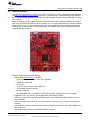
6.2
F5529 LaunchPad™
The MSP-EXP430F5529LP LaunchPad (the "F5529 LaunchPad") is a very inexpensive simple evaluation
module for the MSP430F5529 USB microcontroller. It is an easy way to start developing on the MSP430
MCU, having on-board emulation for programming and debugging, as well as buttons and LEDs for simple
user interface.
Rapid prototyping is simple, thanks to 40-pin Launchpad BoosterPack™ expansion headers, as well as a
wide range of available BoosterPack plug-in modules. You can quickly add features like wireless, displays,
sensors, and much more. You can either design your own BoosterPack or choose among many already
available from TI and elsewhere. The 40-pin interface is compatible with any 20-pin BoosterPack that is
compliant with the standard.
Figure 12. MSP430F5529 LaunchPad
Features of the F5529 LaunchPad include:
• USB-enabled MSP430F5529 16-bit MCU
– Up to 25-MHz system clock; 1.8-V to 3.6-V operation
– 128KB flash; 8KB RAM
– Five timers
– Up to four serial interfaces (SPI, UART, I2C)
– 12-bit analog-to-digital converter
– Analog comparator
– Integrated USB, with a complete set of USB tools, libraries, examples, and reference guides
• Integrated eZ-FET lite emulator, with an application ("backchannel") UART.
• Ability to emulate and develop USB applications with a single USB cable, made possible with an onboard USB hub.
• Power sourced from the USB host. The 5-V bus power is reduced to 3.3 V, using an on-board dc/dc
converter.
• Both male and female 40-pin BoosterPack headers, configured for stacking. 20-pin BoosterPacks can
also be attached.
• Compatible with the 40-pin LaunchPad BoosterPack standard.
SLAA457A – September 2013 – Revised May 2014
Submit Documentation Feedback
Starting a USB Design Using MSP430™ MCUs
Copyright © 2013–2014, Texas Instruments Incorporated
21
Getting Started: Evaluating MSP430 USB
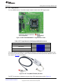
6.3
www.ti.com
MSP430F5529 USB Experimenter's Board
The MSP430F5529 USB Experimenter's Board (MSP-EXP430F5529) has more features on a single board
than any other MSP430 USB evaluation hardware from TI. It has multiple controls, ports, and power
arrangements, allowing a wide variety of applications. Like the F5529 Launchpad, it also has an on-board
emulator.
Figure 13. MSP430F5529 Experimenter's Board
22
Starting a USB Design Using MSP430™ MCUs
SLAA457A – September 2013 – Revised May 2014
Submit Documentation Feedback
Copyright © 2013–2014, Texas Instruments Incorporated
Getting Started: Evaluating MSP430 USB
www.ti.com
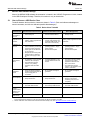
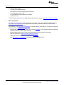
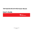
6.4
FET Target Boards
For every MSP430 device, TI provides simple evaluation boards called "FET target boards".
Figure 14. MSP-TS430PN80USB FET Target Board for F552x
Table 6. FET Target Boards for USB-Equipped MSP430 Derivatives
USB-Equipped MSP430 Family
FET Target Board
MSP430F550x, MSP430F5510
MSP-TS430RGC64USB
MSP430F552x
MSP-TS430RGC64USB
MSP-TS430PN80USB
MSP430F563x, MSP430F663x
MSP-TS430PZ100USB
MSP430F565x, MSP430F665x
MSP-TS430PZ100USB
FET target boards are available for every MSP430 derivative, not just the MSP430F5529. However, they
do not have an on-board emulator, as the F5529 LaunchPad and F5529 Experimenter's Board do; and so
they require a FET Tool for emulation.
Figure 15. FET Tool (MSP-FET430UIF) Emulator
The FET Tool interfaces to hardware using the 14-pin JTAG header shown at left in Figure 14.
SLAA457A – September 2013 – Revised May 2014
Submit Documentation Feedback
Starting a USB Design Using MSP430™ MCUs
Copyright © 2013–2014, Texas Instruments Incorporated
23
More Information
www.ti.com
FET target boards contain:
• A socket for the MSP430 device
• The minimum circuitry required for basic operation
• Two pushbuttons and an LED
• All of the MSP430 pins brought out to headers
• A USB connector
The FET target boards relevant to USB-equipped derivatives are shown at http://www.ti.com/msp430usb.
7
More Information
All of the tools and software described in this document can be found at the MSP430 USB landing page:
http://www.ti.com/msp430usb. Check periodically for updates. Information can also be found on the
product pages for individual devices.
For questions, go to http://www.ti.com/support for support options, particularly the TI Engineer-to-Engineer
(E2E) community (http://e2e.ti.com).
• MSP430x5xx and MSP430x6xx Family User's Guide (SLAU208). This document contains architectural
information common to the entire F5xx family.
• Individual device data sheets. These contain parametric and device-specific information.
• USB 2.0 specification (http://www.usb.org/developers/docs/)
• USB Field Firmware Updates on MSP430 MCUs (SLAA452)
• See http://www.ti.com/msp430usb for all things related to MSP430 USB.
24
Starting a USB Design Using MSP430™ MCUs
SLAA457A – September 2013 – Revised May 2014
Submit Documentation Feedback
Copyright © 2013–2014, Texas Instruments Incorporated
www.ti.com
Appendix A USB Glossary
1. Bulk Transfers: One of four data transfer types on the USB bus. Bulk transfers are designed for
moving high volumes of data. They are capable of using any free bandwidth on the bus (that is,
bandwidth not already used by the other transfer types). This allows them to achieve the highest data
rates; but they are given no reserved bandwidth, so on a busy bus, bulk transfers might receive small
bandwidth or experience high latency. Transfer types are determined by the choice of USB interface
type; for example, CDC and MSC interfaces use bulk transfers.
2. Composite USB Device: A physical USB device (one USB connector) that contains more than one
USB interface – for example, two CDC interfaces or CDC+HID. The host enumerates each interface as
a separate logical entity.
3. Control Transfers: One of four data transfer types on the USB bus. Control transfers handle the
administrative tasks of setting up the connection, like reporting USB descriptors. The host also sends
other USB device requests, and the device responds using control transfers. There is a USB endpoint
dedicated for these transfers: endpoint 0 (EP0).
4. Device Class: A defined USB protocol for a particular class of devices. Common device classes
include the Communications Device Class (CDC), Human Interface Device (HID) class, and Mass
Storage Class (MSC).
5. Device Installation: The first time a USB device is enumerated, the host may perform one-time
functions to install the device. For example, Windows records information about the device in the
system registry, using the device's VID and PID as an index. In subsequent enumerations, the host
draws from the registry for much of its information about the device. Device installation may be silent
(mostly invisible to the end user) or, in the case of CDC on Windows, may require user action.
6. Endpoint: The end of a pipe. It acts as a "mailbox" on the USB device for that pipe. A device usually
has more than one active endpoint. When the host communicates on the bus, it first identifies the
physical USB device, then the endpoint number within that device that it wishes to speak to. Endpoints
are assigned specific functions according to the USB interfaces that were created. HID/MSC each use
one IN and one OUT endpoint, while CDC uses two IN and one OUT endpoint. In the MSP430 API
stacks, endpoint management is fully automated by the Descriptor Tool.
7. Enumeration: The process by which a host interrogates a physical USB device to determine what it is
and loads an appropriate driver so that the host application can interface with it. Enumeration happens
every time the device is attached.
8. Interrupt Transfers: One of the four USB data transfer types. Interrupt transfers are designed for
guaranteed latency, bandwidth, and delivery. However, the bandwidth is limited to only a single USB
packet (64 bytes for full-speed USB) per frame (1 ms). Transfer types are determined by the choice of
USB interface type; for example, HID interfaces use interrupt transfers.
9. Isochronous Transfers: One of the four USB data transfer types. Isochronous transfers provide
guaranteed latency and bandwidth but not delivery. That is, if error checking shows corrupted data, the
attempt is not retried. This type is intended for streaming audio and video -- applications in which a
retry would result in an interruption and thus be more noticeable to the user than simply missing the
packet.
10. INF (*.inf) file: A text-based file required during any USB device installation on Windows, allowing
Windows to associate the device with a particular driver. For some device classes, Windows contains
the INF internally, allowing for a silent device installation. For CDC, Windows prompts the end user for
the INF file.
11. Pipe: A single line of communication between host and device. Pipes are either IN (into the host) or
OUT (out of the host). They are characterized by a particular transfer type (for example, bulk or
interrupt).
12. Product ID (PID): A unique 16-bit value assigned by a USB hardware vendor to one of its products. A
VID and PID pair uniquely identifies a product type. (As a rule of thumb, if the USB descriptors of two
products differ in any way, they should have different PIDs.)
13. USB-IF: The USB Implementers Forum. This is the standards body that defines USB specifications,
governs USB certification, runs compliance workshops, and owns the legal rights to the USB logo.
14. USB Host: USB is hierarchal, with one (and only one) host that controls all communication.
SLAA457A – September 2013 – Revised May 2014
Submit Documentation Feedback
Starting a USB Design Using MSP430™ MCUs
Copyright © 2013–2014, Texas Instruments Incorporated
25
Appendix A
www.ti.com
15. USB Device: Also called a USB function. This is a logical or physical entity on the bus that contains
one or more USB interfaces. It possesses one upstream-capable USB connector.
16. USB Hub: A device that provides communication between one upstream connector and multiple
downstream connectors, allowing more USB devices to be attached to a host. In any given bus
configuration, a device is either a host, device, or hub.
17. USB Interface: A logical USB entity that performs a particular function. An interface is typically
associated with a particular device class – for example, a "CDC interface".
18. USB Descriptors: Data structures contained within a physical USB device that describe the device
(including the interfaces it supports) and its capabilities. The host reads these during enumeration.
19. USB Serial Number: A unique string that allows a host to differentiate between devices attached to it
that contain the same VID and PID values.
20. USB speeds: A USB connection is characterized by one of four speeds: low-speed (1.5 Mbps), fullspeed (12 Mbps), high-speed (480 Mbps), or super-speed (4.8 Gbps). MSP430 MCUs are USB 2.0
full-speed devices. All MSP430 USB traffic is full-speed.
21. VBUS: The host is required to make 5-V power available to the device through the USB cable. The
name of this power rail is VBUS. In addition to sourcing power, the USB device uses VBUS to
determine whether or not an active host is present. Devices often respond to a VBUS-on event by
asserting their presence to the host by pulling up the D+ signal.
22. Vendor ID (VID): A unique 16-bit value assigned by the USB Implementers Forum to a particular
USB hardware vendor.
26
Starting a USB Design Using MSP430™ MCUs
SLAA457A – September 2013 – Revised May 2014
Submit Documentation Feedback
Copyright © 2013–2014, Texas Instruments Incorporated
Revision History
www.ti.com
Revision History
Changes from Original (September 2013) to A Revision ............................................................................................... Page
•
•
Added the paragraph that starts "The pullup resistor is specified...".............................................................. 17
Added the paragraph that starts "The diode on VBUS is placed ..." .............................................................. 17
NOTE: Page numbers for previous revisions may differ from page numbers in the current version.
SLAA457A – September 2013 – Revised May 2014
Submit Documentation Feedback
Copyright © 2013–2014, Texas Instruments Incorporated
Revision History
27
IMPORTANT NOTICE
Texas Instruments Incorporated and its subsidiaries (TI) reserve the right to make corrections, enhancements, improvements and other
changes to its semiconductor products and services per JESD46, latest issue, and to discontinue any product or service per JESD48, latest
issue. Buyers should obtain the latest relevant information before placing orders and should verify that such information is current and
complete. All semiconductor products (also referred to herein as “components”) are sold subject to TI’s terms and conditions of sale
supplied at the time of order acknowledgment.
TI warrants performance of its components to the specifications applicable at the time of sale, in accordance with the warranty in TI’s terms
and conditions of sale of semiconductor products. Testing and other quality control techniques are used to the extent TI deems necessary
to support this warranty. Except where mandated by applicable law, testing of all parameters of each component is not necessarily
performed.
TI assumes no liability for applications assistance or the design of Buyers’ products. Buyers are responsible for their products and
applications using TI components. To minimize the risks associated with Buyers’ products and applications, Buyers should provide
adequate design and operating safeguards.
TI does not warrant or represent that any license, either express or implied, is granted under any patent right, copyright, mask work right, or
other intellectual property right relating to any combination, machine, or process in which TI components or services are used. Information
published by TI regarding third-party products or services does not constitute a license to use such products or services or a warranty or
endorsement thereof. Use of such information may require a license from a third party under the patents or other intellectual property of the
third party, or a license from TI under the patents or other intellectual property of TI.
Reproduction of significant portions of TI information in TI data books or data sheets is permissible only if reproduction is without alteration
and is accompanied by all associated warranties, conditions, limitations, and notices. TI is not responsible or liable for such altered
documentation. Information of third parties may be subject to additional restrictions.
Resale of TI components or services with statements different from or beyond the parameters stated by TI for that component or service
voids all express and any implied warranties for the associated TI component or service and is an unfair and deceptive business practice.
TI is not responsible or liable for any such statements.
Buyer acknowledges and agrees that it is solely responsible for compliance with all legal, regulatory and safety-related requirements
concerning its products, and any use of TI components in its applications, notwithstanding any applications-related information or support
that may be provided by TI. Buyer represents and agrees that it has all the necessary expertise to create and implement safeguards which
anticipate dangerous consequences of failures, monitor failures and their consequences, lessen the likelihood of failures that might cause
harm and take appropriate remedial actions. Buyer will fully indemnify TI and its representatives against any damages arising out of the use
of any TI components in safety-critical applications.
In some cases, TI components may be promoted specifically to facilitate safety-related applications. With such components, TI’s goal is to
help enable customers to design and create their own end-product solutions that meet applicable functional safety standards and
requirements. Nonetheless, such components are subject to these terms.
No TI components are authorized for use in FDA Class III (or similar life-critical medical equipment) unless authorized officers of the parties
have executed a special agreement specifically governing such use.
Only those TI components which TI has specifically designated as military grade or “enhanced plastic” are designed and intended for use in
military/aerospace applications or environments. Buyer acknowledges and agrees that any military or aerospace use of TI components
which have not been so designated is solely at the Buyer's risk, and that Buyer is solely responsible for compliance with all legal and
regulatory requirements in connection with such use.
TI has specifically designated certain components as meeting ISO/TS16949 requirements, mainly for automotive use. In any case of use of
non-designated products, TI will not be responsible for any failure to meet ISO/TS16949.
Products
Applications
Audio
www.ti.com/audio
Automotive and Transportation
www.ti.com/automotive
Amplifiers
amplifier.ti.com
Communications and Telecom
www.ti.com/communications
Data Converters
dataconverter.ti.com
Computers and Peripherals
www.ti.com/computers
DLP® Products
www.dlp.com
Consumer Electronics
www.ti.com/consumer-apps
DSP
dsp.ti.com
Energy and Lighting
www.ti.com/energy
Clocks and Timers
www.ti.com/clocks
Industrial
www.ti.com/industrial
Interface
interface.ti.com
Medical
www.ti.com/medical
Logic
logic.ti.com
Security
www.ti.com/security
Power Mgmt
power.ti.com
Space, Avionics and Defense
www.ti.com/space-avionics-defense
Microcontrollers
microcontroller.ti.com
Video and Imaging
www.ti.com/video
RFID
www.ti-rfid.com
OMAP Applications Processors
www.ti.com/omap
TI E2E Community
e2e.ti.com
Wireless Connectivity
www.ti.com/wirelessconnectivity
Mailing Address: Texas Instruments, Post Office Box 655303, Dallas, Texas 75265
Copyright © 2014, Texas Instruments Incorporated