1
Firecycle 427e
January 12, 2007
firecycle® III
multi-cycle deluge
system
TECHNICAL DATA
The Viking Corporation, 210 N Industrial Park Road, Hastings MI 49058
Telephone: 269-945-9501 Technical Services 877-384-5464 Fax: 269-945-4495 Email: [email protected]
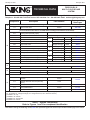
Component
A
Description
Part Numbers
Corresponding
Data Pages
Various
500 - 508
System Valve
A.1
Flow Control Valve
Firecycle® III Trim
(Trim and Flow Control Valve is included with the Package Part Numbers shown below)
B
C
B.1
Priming Valve (Normally Open)
B.2
Strainer
B.3
1/8” Restricted Orifice
Firecycle® III Valve and Trim Packages
1-1/2”
B.4
Spring Loaded Check Valve
B.5
Alarm Test Valve (Normally Closed)
B.6
Drip Check Valve
B.7
Drain Check Valve
B.8
Alarm Shut-Off Valve (Normally Open)
B.9
Pressure Operated Relief Valve (PORV)
2”
B.10
Emergency Release
B.11
Priming Pressure Water Gauge and Valve
B.12
Water Supply Pressure Gauge and Valve
B.13
Drain Cup
B.14
Flow Test Valve (Normally Closed)
C.1
Water Flow Alarm Pressure Switch
3”
4”
6”
8”
Angle
10100
Straight Through
126911
442 a-b
442 e-f
Angle
10101
445 a-b
Straight Through
126942
442 e-f
Angle
10102
448 a-b
Straight Through
126183
445 e-f
Angle
10103
448 a-b
Straight Through
123483
448 e-f
Angle
10104
448 a-b
Straight Through
123513
448 e-f
Straight Through
121004
448 e-f
Water Flow Alarm Equipment
09470
705 a-b
-
-
Riser
D
D.1
Water Supply Control Valve
D.2
System Drain (Recomended)
Sized according to NFPA 13
Release System
E
E.1
Release Solenoid Valve # 1 (Normally
Closed)
Various
E.2
Release Solenoid Valve # 2 (Normally
Open)
11595
E.3
Firecycle® III Control Panel
Various
433 a-h
E.4
Firecycle® Detector
Various
417 a-d
E.5
Firecycle® Detector Cable
Various
419 d-f
274 a-b
Footnotes: Add inlet and outlet designation to base part number for straight through style valves.
(TT - Threaded, FF - Flange X Flange, FG - Flange X Groove, GG - Groove X Groove)
1 Available in TT only
2 Available in TT and GG
3 Available in FF, FG and GG
4 Available in FF and GG
Table 1 - System Components
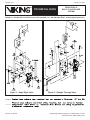
Refer to Figures 1 and 2 for component Identification
Note: When viewing this Data Page online, blue text represents hyper links and will open the desired data page when clicked.