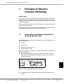
1
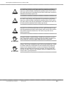
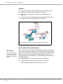
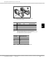
Operating Manual Small Conveyor Units Series KF and KR Operating Manual for AViTEQ Small Conveyor Units KF and KR Intended Use The AViTEQ small conveyor units are used to l remove, transport, convey, measure out, and distribute small grain bulk goods and small parts. AViTEQ small conveyor units have a large range of applications and are used in almost all branches of industry, from automation technology to the construction of packaging machines. Please observe the other instructions regarding proper usage in Chapter 1.3! ©1999 AViTEQ Vibrationstechnik GmbH Version 10/1999 0–2 Safety Notes You will find three different types of symbols in this operating manual which are intended to point out important information: DANGER! The DANGER warning describes procedures or conditions which could have dangerous or even life-threatening consequences for the person installing or using the equipment. You will find this information associated with procedures in which a danger of damage to equipment exists. This damage could also result in injury to personnel (e.g., from a fire!) ATTENTION! Notes provide information about individual procedures. Notes explain circumstances, clarify terminology or provide tips for simplifying processes or procedures. NOTE Although the conveyor devices were developed taking all safety measures into account, errors are possible. In the interest of your safety and that of your colleagues, observe the following information: DANGER! When the unit is connected to the mains, a lethal voltage is present inside the controller and the small conveyor unit. Touching electrically live components can be lethal! Before switching on mains power, ensure that no live parts can be touched. Close the controller’s lid! Inadequate installation may cause the conveyor device to fall down possibly causing injuries. Ensure that the rubber feet on the chassis are bolted on tight! DANGER! DANGER! 0–3 Non-sterile conveyors in applications of the pharmaceutical and food processing industries represent a significant health risk through the spreading of germs. For this reason, only conveyors in special paintwork with sterilizable surface may be used in such applications. Operating Manual for AViTEQ Small Conveyor Units KF and KR DANGER! Non-sterile small conveyor units in applications in the pharmaceutical industry represent a significant health risk through the spreading of germs For this reason, only small conveyor units in the pharma version, with a surface that can be decontaminated and sterilized, may be used. DANGER! Non-sterile small conveyor units in applications in the food processing industry represent a significant health risk through the spreading of germs For this reason, only small conveyor units with special paintwork, or the pharma version with a surface that can be decontaminated and sterilized, may be used. DANGER! Explosions can be life-threatening and may result in significant damage to equipment.Take appropriate precautions when using the small conveyor units in environments where an explosion hazard exists! The small conveyor units have no explosion protection! Unsuitable controllers, operation without controller, and connection to incorrect mains voltage/mains frequencies may damage the drive. Make sure that the connection values are correct and compare them with the unit’s type labels! ATTENTION! ATTENTION! ©1999 AViTEQ Vibrationstechnik GmbH Changes in the air gap, the tightening torque of the spring mounting bolts, installation without rubber feet, and deviations from the intended working weight may lead to excessive heating of the drive, to short circuits between electromagnet windings, and eventually to the destruction of the drive. Do not open the drive yourself! If in doubt, contact us! We are happy to help you in adapting the small conveyor units to your requirements! Version 10/1999 0–4 © 1999 AViTEQ Vibrationstechnik GmbH COPYRIGHT The AViTEQ small conveyor units of the KF and KR series, the VIBTRONIC controllers, and this operating manual are protected by copyright. Any reengineering of the units will result in criminal prosecution. All rights to this operating manual are reserved, including reproduction via photo mechanical, print, data or any other possible medium, as well as in translation. Reproduction of this operating manual, complete or in part, requires the written consent of AViTEQ Vibrationstechnik GmbH. VIBTRONIC is a registered and protected trademark of AViTEQ Vibrationstechnik GmbH. This operating manual supports the intended use and appropriate deployment of AViTEQ small conveyor units. For this purpose, the operating manual describes details that are significant for the product's operation. In particular, the operating manual does not assure that any properties are present, or that certain results will be achieved by the product's deployment. Prior to publication, this operating manual has been subjected to thorough verification. AViTEQ Vibrationstechnik GmbH is only liable for faulty content in the operating manual in cases of intent or gross negligence. This liability is restricted to cases where faulty content renders the product worthless or useless, or reduces its value or usability, for its usual purpose or any purpose assumed under the contract. Evidence for faulty content, the damage, and the causality regarding both cause and extent of the claim, has to be supplied by the purchaser. AViTEQ Vibrationstechnik GmbH is not liable for damage or consequential damage resulting from the use of the operating manual. This does not apply to faulty content of the operating manual. We are always grateful for suggestions and criticism! Unless otherwise stated, the relevant state of engineering is that at the time of the combined delivery of the product and the operating manual from AViTEQ Vibrationstechnik GmbH. The product is subject to technical changes without prior notice. Previous operating manuals no longer apply. The General Conditions of Delivery Domestic and Abroad of AViTEQ Vibrationstechnik GmbH apply in their current version. Do you have questions? Or problems with installation and commissioning? Give us a call! We'll be glad to help you! AViTEQ Vibrationstechnik GmbH Goldsteinstraße 238 60528 Frankfurt/Main Telephone +49 (0) 69 - 66 99 - 302 Fax +49 (0) 69 - 66 99 - 205 Frankfurt, Germany 14. Oktober 1999 0–5 9918 Operating Manual for AViTEQ Small Conveyor Units KF and KR Chapter Contents General notices regarding this Operating Manual, our Conditions of Sale, the Warranty and the Intended Use of the small conveyor units 1 Transport, Storage, Extent of Delivery and Disposal 2 Here, you’ll learn all about the mechanical installation of the unit, the installation of working units, and the attachment to the base plate 3 Basics of the controller and its selection. 4 To the point: Commissioning Step by Step 5 Not to be forgotten: Troubleshooting, improving the transport performance 6 Did you know how the conveyor works? And how it is matched to its payload? Read it here! 7 Search and find: the Index ©1999 AViTEQ Vibrationstechnik GmbH Version 10/1999 8 0–6 Contents CONTENTS 1 We are Partners. 1-1 1.1 1.2 1.3 1.4 1.5 1.6 About this operating manual ...............................................................................................1-1 Product liability and warranty..............................................................................................1-3 Field of application and intended use .................................................................................1-5 Installation and operating personnel...................................................................................1-6 Safety precautions and responsibilities of the operator ....................................................1-7 EU directive ................................................................................................................ ..........1-7 2.1 2.2 2.3 2.3.1 2.3.2 Transport and storage..........................................................................................................2-1 Contents of delivery .............................................................................................................2-2 Disposal ................................................................................................................................2-2 Packing materials .................................................................................................................2-2 Materials used in the units...................................................................................................2-3 2 Extent of Delivery, Packing, Disposal 3 Installation of the Small Conveyor Drive 3.1 3.1.1 3.1.2 3.1.3 3.1.4 3.2 3.2.1 3.2.2 3.2.3 4 5 6 7 8 7-1 Construction and principle of operation of the small conveyor units ...............................7-1 Alignment of the units .........................................................................................................7-2 Two-body resonance system ..............................................................................................7-2 Implementation in practice ..................................................................................................7-2 Tuning data for the KF and KR series ..................................................................................7-3 INDEX i 6-1 Preventative maintenance ...................................................................................................6-1 Troubleshooting ...................................................................................................................6-2 Principles of Vibration Conveyor Technology 7.1 7.2 7.2.1 7.2.2 7.3 5-1 Commissioning ....................................................................................................................5-1 24 hour test ..........................................................................................................................5-3 Cleaning................................................................................................................................5-4 Maintenance and Troubleshooting 6.1 6.2 4-1 Suitable controllers ..............................................................................................................4-1 VIBTRONIC controllers.........................................................................................................4-1 Description of functionality..................................................................................................4-1 Type designation ..................................................................................................................4-2 Combinations of small conveyor drive / controller ............................................................4-3 Connection notes for VIBTRONIC controllers.....................................................................4-4 Controllers from third party manufacturers........................................................................4-5 Cabling..................................................................................................................................4-6 Commissioning and Operation 5.1 5.2 5.3 3-1 Installation of the working unit ............................................................................................3-1 Your own working unit.........................................................................................................3-1 Before installation ................................................................................................................3-2 Notes regarding the attachment with bolts ........................................................................3-2 Flow chart - explanations.....................................................................................................3-4 Mounting the small conveyor unit on the base plate.........................................................3-7 Before installation ................................................................................................................3-7 Flow chart - explanations.....................................................................................................3-9 Sound pressure level .........................................................................................................3-10 Selection and Installation of the Controller 4.1 4.2 4.2.1 4.2.2 4.2.3 4.2.4 4.3 4.4 2-1 8-i Operating Manual for AViTEQ Small Conveyor Units KF und KR 1 We are Partners. Chapter outline Although you might want to get started immediately with our small conveyor unit/drive, we would like you to read this chapter first. It provides a summary of the contents of the operating manual and settles our legal relationship as parties to a contract. 1 1.1 About this operating manual For whom? This operating manual is intended for the l installation technician who unpacks, installs, and commissions the small conveyor unit l controller engineer who connects the unit to the controller, installs the controller in the cabinet if required, and connects the controller to the AC mains. All work on the small conveyor unit must be undertaken by qualified personnel (a trained mechanic, an electrotechnically qualified person according to IEC 364 and DIN VDE 0105 Part 1, or an electrotechnically trained person acccording to IEC 364 and DIN VDE 0105 Part 1). Electrically live components. Risk of electrocution unless the mains is disconnected. During installation and commissioning, observe the safety notes above! DANGER! Additional publications Depending on the contents shipped, this manual will be supplemented by separate brief descriptions: NOTE ©1999 AViTEQ Vibrationstechnik GmbH l controller operating manual l controller connection schematics l brief description of storage container and rattler (special accessories) l leaflet "small conveyor units" Some versions of the small conveyor systems are available as a PHARMA version for the pharmaceutical industry. For use in the pharmaceutical industry, you must use the version with special sterilizable paintwork, or the PHARMA version "CR". Version 10/1999 1–1 We are Partners. – About this operating manual Definitions l Small conveyor drive: the compact drive block with the vibration system l Working unit: the actual conveyor unit (pipe, rail, or trough) l Small conveyor unit: working unit attached to the small conveyor (see Figure 1.1). l Controller: the separately shipped controller unit associated with the small conveyor unit that is used for connection to the AC mains. Figure 1.1 Versions of small conveyor units with different working units. Special symbols in this operating manual Revision date On the bottom right hand side of this operating manual, the version number tells you the date when the page was last updated. Earlier in this manual, you should have learned how we indicate safety notes. If you have any questions about safe work practices regarding small conveyor units and their environment, you should give us a call! We do not want you to endanger yourself or others just because the possible dangers were not clear to you! For your convenience and orientation, we use the following special indicators in this operating manual: l A round bullet indicates a listing of characteristics and conditions. ã A checked box tells you to check something, or read a summary. F The pointing finger indicates steps that you have to carry out. 1–2 Operating Manual for AViTEQ Small Conveyor Units KF und KR 1.2 Product liability and warranty The small conveyor systems correspond to the current state of technology. Their specified functions have been tested prior to shipping. AViTEQ Vibrationstechnik GmbH carries out product and market research to aid further development and continuous improvement. Should malfunctions or failures occur despite these preventative measures, please contact our service department! We guarantee that appropriate measures for the repair of the defect will be taken immediately. 1 Warranty Conditions The Allgemeinen Lieferbedingungen Inland und Ausland (General Conditions of Delivery Domestic and Abroad) of AViTEQ Vibrationstechnik GmbH apply in their current version. We guarantee the functioning of the product as described in this operating manual for a period of 12 months after the date of delivery as stated on the delivery invoice. The condition for free repair is adherence to the operating manual when storing, shipping, installing, commissioning and operating the product. We guarantee that the product is free of faults according to product information published by us, and according to the relevant statements in this operating manual. Beyond that, no product properties are guaranteed. AViTEQ Vibrationstechnik GmbH accepts no responsibility for the economical use of the product or for proper operation if used for other purposes than those defined in Chapter 1.3. Warranty exclusions Customers and third parties must consult with AViTEQ Vibrationstechnik GmbH and obtain our written consent before undertaking work inside or otherwise interfering with the product subject to the contract. Otherwise, AViTEQ Vibrationstechnik GmbH does not accept liability for resulting damage to equipment, injuries and other consequential damage to the product subject to the contract or to other property. Entering into or interfering with the equipment also renders any warranty null and void. AViTEQ Vibrationstechnik GmbH does not accept liability beyond the warranty entitlements stated in our terms of business on which the contract is based. This applies in particular to claims arising from loss of profit or other damage to customer assets. This restriction does not apply if the cause of the damage results from intent or gross negligence. Neither does it apply if the customer’s claim for damages is based on the lack of a property that has been promised. If an obligation under the contract is violated by negligence, AViTEQ Vibrationstechnik GmbH’s liability is limited to the damage that was foreseeable. Warranty is excluded in particular when the units are used in environments, for purposes, or connected to power supplies that are not suitable for small conveyor units, that are faulty, or do not represent the common state of technology. In particular, we do not accept liability for damage resulting from unsuitable or improper use, incorrect installation or commissioning by the customer or third parties, natural wear and tear, incorrect or negligent handling or unsuitable consumables. The same applies to spare parts, chemical, electrochemical or electrical influences unless the damage is caused by AViTEQ Vibrationstechnik GmbH. Compensation ©1999 AViTEQ Vibrationstechnik GmbH Version 10/1999 1–3 We are Partners. – Product liability and warranty for damage other than damage to the product subject to the contract is excluded except in cases of intent, gross negligence or culpable violation of significant contract obligations by AViTEQ Vibrationstechnik GmbH. Also, we do not accept liability for damage to conveyor and automation plants caused by a malfunction of the product or by mistakes in the content of the operating manual. We do not accept liability for damage caused by accessories not supplied or certified by AViTEQ Vibrationstechnik GmbH. AViTEQ Vibrationstechnik GmbH is not responsible for the violation of patent rights or other rights of third parties outside the Federal Republic of Germany. We would like to point out that we are not liable for damage to the product subject to the contract, or for consequential damage to other property, if the damage is caused by non-observation of safety regulations and/or warning notices. When entering the contract, the customer is obliged to point out explicitly if the product is intended for private use and will be used by the customer predominantly for this purpose. 1–4 Operating Manual for AViTEQ Small Conveyor Units KF und KR 1.3 Field of application and intended use Field of application The AViTEQ small conveyor units may be used for removal, transportation, feeding, distribution, and measuring out of small grain bulk materials and small parts. The small conveyor units are not intended to be used for other purposes. Small conveyor units are used as components of conveyor and automation plants. Sample applications of AViTEQ small conveyor units of the KF and KR series as well as the CR series in the PHARMA version are: l general industry use for the transport of, e.g., corundum abrasive, chips, nuts, granules or other plastic parts l pharmaceutical industry for the conveying of pills, capsules, ampoules, and granules („CR“ version only) l food industry for the transportation of, e.g., sugar, tea, baking ingredients, cereals, milk powder, spices, muesli 1 We are happy to carry out experiments for products whose transportation properties are unkonwn. Give us a call! NOTE Under no circumstances must the small conveyor units be used for the following: DANGER! ©1999 AViTEQ Vibrationstechnik GmbH l Do not use with liquids, powder with particle diameters of less than 50 µm, sticky items, items that may jam, bulky items, soft items and fragile items (thin glass)! l Do not use for operation in environments with explosion hazards (explosives, gassy environments, dust explosion hazard)! This does not apply to the „Ex“ version of the units! l Do not use if product temperatures exceed 100 °C or in environmental temperatures below -25 and above +40 °C, or in tropical climate! The units are designed for operation in moderate climatic environments (DIN IEC 721)! l Do not use in food processing plants (except type KF with special paintwork or the PHARMA version „CR“)! l Do not use in the pharmaceutical industry or in pharmaceutical plants (except for the PHARMA version „CR“)! The surfaces of the standard versions cannot be decontaminated and therefore cannot be used in sterile environments. For applications in the pharmaceutical industry, you must only use small conveyor units in the PHARMA version „CR“! Version 10/1999 1–5 We are Partners. – Installation and operating personnel Connection to controllers The small conveyor units must only be connected to the AC mains via special VIBTRONIC controllers. A suitable controller exists for every version of the small conveyor drives and units. Other control and connection options are not included. If a small conveyor drive is connected directly to the AC mains orto an unsuitable controller, it may be destroyed. Only use the appropriate controller! ATTENTION! Service, Repair and Maintenance Neither the small conveyor unit nor the controller contain components that may be maintained or repaired by the installer or user. Do not open the units under any circumstances. In case of a fault, send them back to us if you would like to have them repaired. DANGER! If mains voltage is applied, a lethal voltage is present inside the controller and the small conveyor drive. Touching electrically live components can be lethal! Before switching on mains power, ensure that no live parts can be touched. The controller’s lid should be closed! 1.4 Prior to installation and/or commissioning, you must have acquainted yourself with all details and connection options of the small conveyor unit. Installation and operating personnel Persons involved with installation, commissioning, assembly, disassembly, adjustment or maintenance must have read and understood this operating manual in its entirety; in particular the safety notes. If you have any questions, we are happy to help you! All work on the small conveyor unit must be undertaken by qualified skilled personnel (electrotechnically qualified or trained person according to IEC 364 and DIN EN 60204-1). Maintenance on the small conveyor units may only be carried out by service personnel authorized and trained by AViTEQ Vibrationstechnik GmbH, Frankfurt. AViTEQ Vibrationstechnik GmbH, Frankfurt, is not liable for injuries or damage to property if this is not observed. 1–6 Operating Manual for AViTEQ Small Conveyor Units KF und KR 1.5 Safety precautions and responsibilities of the operator l This operating manual is part of the small conveyor unit and must be available to qualified personnel at any time. l Qualified personnel must have appropriate tools and test equipment at their disposal. l Qualified personnel must be trained in safe work practices and must be familiar with the safety notes on pages 0-3 and 0-4. l The operator must obtain a local operating permit and observe any conditions relating to it. l VDE regulations in their current version are to be observed. This applies in particular to EN 60 204-1 (VDE 0113) regarding machine safety and electrical equipment of machines, and VDE 100 regarding installation of heavy current equipment with voltage ratings of up to 1000 V. l The operator may only use the small conveyor unit if it is in perfect condition and in a proper state. 1 Please observe the following: l All work on the small conveyor unit requires that you observe the shutdown procedures described in the operating manual. l You must avoid any work practice that compromises safety in relation to the small conveyor unit. You must not disable any safety mechanisms! l Any changes relating to the small conveyor unit that could compromise safety must be reported to the operator immediately. 1.6 EU directive The small conveyor unit is not a standalone machine in the sense of the EU Machinery Directive 89/392/EEC, and intended for use together with another machine only. Operation is prohibited until it has been established that the machine that is handed to the operator complies with the regulations of the EU directive. The small conveyor unit was built in accordance with these regulations. ©1999 AViTEQ Vibrationstechnik GmbH Version 10/1999 1–7 We are Partners. – EU directive 1–8 Operating Manual for AViTEQ Small Conveyor Units KF and KR 2 Extent of Delivery, Packing, Disposal Chapter Outline For storage and transport, certain measures must be observed in order to prevent damage to the units. The contents of the delivery must be checked after unpacking. The packing material should be disposed of properly. What do you do with AViTEQ small conveyor units when you no longer need them? The return guarantee. 2.1 l NOTE 2 Transport and storage Delivery: small conveyor unit and accessories are delivered in appropriate packing so that they reach their destination without damage. If the outer packaging shows heavy damage that could indicate damage to the contents, contact the forwarding agent! In further proceedings, note the forwarding agent’s General Conditions of Business. Otherwise, formalities may jeopardize your entitlement to compensation! F Storage: unless special agreements concerning packing and storage have been made, the units, either packed or unpacked, must be stored and transported under "normal" conditions. This means: in enclosed rooms with ambient temperatures between -10 and +45 °C and a relative humidity not exceeding 80 %. When transporting the unpacked unit, it is easy to avoid damage: F Always grab the small conveyor drive from the underside if you wish to carry it! Never lift it by the working unit! F Avoid contact with pointed or sharp (metallic) objects that could damage the protective lacquer coating! F Always place the unit onto a secure support base and position, such that the unit cannot tip or fall down. ATTENTION! ©1999 AViTEQ Vibrationstechnik GmbH Transporting and storing the units under inappropriate conditions may cause permanent damage. Such damage may not be detectable from the outside. AViTEQ declines any responsibility in this case and is not liable for the consequences. Version 10/1999 2–1 Extent of Delivery, Packing, Disposal – Contents of delivery 2.2 Contents of delivery ã After unpacking, check that all parts are undamaged and complete according to the package slip and as stated on the cover sheet of the shipping documents. ã Compare the data on the type labels of the small conveyor drive and the controller with the delivery invoice and order documents! ã Check whether the small conveyor drive and controller match, by referring to the table in Chapter 4 of this operating manual! Unauthorised combinations result in destruction of the small conveyor drive and controller! Only connect compatible devices! ATTENTION! ã Verify that the small conveyor drive was delivered with special paintwork for use in the food industry, or in version „CR“ for use in the pharmaceutical industry. 2.3 NOTE Disposal AViTEQ is not responsible for the disposal of packing material, the small conveyor units, and accessories. However, we do offer to take back all small conveyor units and accessories delivered by AViTEQ since 1998 with all charges paid for delivery at AViTEQ Vibrationstechnik, Frankfurt. AViTEQ guarantees correct disposal free of charge for the sender. This offer is valid on the condition that the units are returned in clean condition, free of product residue and dirt. Prior to disposal by AViTEQ, this must be confirmed in writing by the sender. 2.3.1 Packing materials The following materials are used by AViTEQ for delivering small conveyor units, depending on the type of transport: l Polyethylene foil (PE) for device protection l Corrugated cardboard for outer and inner packing l Wooden cases for outer packing l Paper shavings as filler material l Styrofoam (Flo-Pack) as filler and cushioning material. All packing materials should be disposed of in accordance with local regulations of the delivery destination. 2–2 Operating Manual for AViTEQ Small Conveyor Units KF and KR Cardboard containers and paper packing tapes can be recycled within the RESY Disposal and Re-utilisation System. Where used, packaging foil, packing tapes, and foam foils are made from polyethylene (PE), the CFC-free cushions are usually made from polystyrene foam (PS). These packaging materials consist of pure carbohydrates and are thus recyclable. In special cases, we use steel packing bands and wooden cases free of chemical treatment. 2.3.2 Materials used in the units AViTEQ accepts used units for free disposal if they are delivered at customers’ expense to AViTEQ Vibrationstechnik GmbH, Frankfurt. In case of disposal by the customer, and when exchanging components, the current local waste and disposal regulations apply and should be observed. AViTEQ does not accept any responsibility for parts and components that have been disposed of improperly! 2 The small conveyor drive consists of, among others, the following materials: l Magnet: iron core, copper wire (isolated wire with lacquer), plastic resin l Springs: spring steel or glass fibre reinforced plastic l Housing: base from cast iron or steel, base plate made of cast aluminium and steel, brass spring washers, and other steel components ( St 37 or VA) l For the disposal of the controller, the regulations for the disposal of electronic parts and components apply. l The power semiconductors (thyristor and diode modules) used do not contain beryllium and thus may be disposed of as electronic waste. If required, AViTEQ is able to supply detailed information on the materials used. In case of doubt, take advantage of our disposal offer! NOTE ©1999 AViTEQ Vibrationstechnik GmbH Version 10/1999 2–3 Extent of Delivery, Packing, Disposal – Disposal 2–4 Operating Manual for AViTEQ Small Conveyor Units KF and KR 3 Installation of the Small Conveyor Drive Chapter Outline Unless the small conveyor unit was delivered with a working unit attached, the channel, trough, or rail must first be bolted onto the small conveyor drive. Afterwards, the entire small conveyor unit has to be positioned and bolted firmly onto the base plate or the support. 3.1 Installation of the working unit If the small conveyor unit was delivered by AViTEQ complete with the working unit assembled, you may skip ahead to Chapter 3.2 „Mounting the small conveyor unit on the base plate“ on page 7 now. NOTE 3 3.1.1 Your own working unit If you want to build your own working unit, please observe the following hints: F The body of the channel has to be stiff to avoid bending. In the case of large lengths/widths and low side walls, sideway folding of the edges or other stiffening measures may be required to achieve this. If required, ribs or rails have to be attached. However, this must not interfere with the attachment of the channel! F Operating noise: the small conveyor drive generates a sound pressure level of less than 70 dB(A) without considering the working unit or the transported material. NOTE Depending on the construction of the working unit and the acoustic properties of the material transported, the sound pressure level of the operational small conveyor unit may exceed 70 dB(A). It is the operator's responsibility to ensure adherence to the sound pressure level permitted by means of suitable noise protection measures! F The center of mass of the channel or rail should be within the front section (outlet side) of the small conveyor drive. F When placing the mounting holes, use the information in the AViTEQ leaflet "small conveyor units“. Do not drill any additional holes into the small conveyor drive! Only use the threaded holes on the small conveyor drive! ©1999 AViTEQ Vibrationstechnik GmbH Version 10/1999 3–1 Installation of the Small Conveyor Drive – Installation of the working unit F For correct alignment of the vibration system, it is best to inform AViTEQ Vibrationstechnik GmbH, Frankfurt, about the actual working weight (not including transported goods) when ordering the small conveyor drive! It is possible to run longer transport systems (channel or rail) with several successive small conveyor drives. Ask AViTEQ about it! NOTE 3.1.2 Before installation F Put the small conveyor drive onto a solid and flat surface! F Have the mounting bolts for the working unit ready. Ensure that the bolts have the correct length! F The controller must be separated from the mains if it has already been connected to the small conveyor drive. DANGER! If there is insufficient support, the conveyor may fall off the assembly table and, under the worst circumstances, may cause injuries. You should therefore ensure a safe support! F Follow the installation steps in the following diagram (see Figure 3.5 on page 5) and read the associated explanations. This procedure will simplify the assembly for you! 3.1.3 Notes regarding the attachment with bolts F Install the working unit by bolting it onto the small conveyor drive. Depending on the version of the small conveyor drive, the bolts are inserted from above, from the side, or from the face (positions no. 7, 8, and 9 in the installation diagram, Figure 3.5). The picture shows examples of KF drives for working unit attachment from above and from the side: F Only use the bolts specified for the individual small conveyor drives in table 3.2! F Please observe the tightening torques speficied in table 3.3! F Ensure that the attachment bolts are not too long! If they are, the working unit may not be able to be attached, or the bolts ends pointing to the inside restrict the movement of the upper part of the small conveyor drive. F Do not drill holes into the bottom of the channel! Protruding bolt heads obstruct the product flow. Rather, you should use joints on the side or underside of the working unit for the attachment to the small conveyor drive. 3–2 Operating Manual for AViTEQ Small Conveyor Units KF and KR Figure 3.1 Working unit attachment: holes on the side (drive on left) and on top (drive on right) Drive Attachment from above Attachment to face Attachment to side (special version R2) KF 0,3 M4 (4...10 mm) - M4 (4...8 mm) KF 0,5 M5 (4...10 mm) - M5 (4...10 mm) KF 0,7 M6 (5...14 mm) - M6 (5...14 mm) KF 0,9 M8 (6...16 mm) - M6 (5...14 mm) Table 3.2 3 Working unit attachment bolt size for small conveyor drives The maximum depth that the bolts may reach within the small conveyor unit’s attachment plate is specified in parentheses. Screw type Tightening Torque (Nm) M4 2.4 Nm M5 5 Nm M6 8 Nm M8 20 Nm Bolt quality 8.8 Table 3.3 ©1999 AViTEQ Vibrationstechnik GmbH Tightening torques for working unit attachment bolts Version 10/1999 3–3 Installation of the Small Conveyor Drive – Installation of the working unit Detuning the eigenfrequency reduces the reliability of the operation! Do not loosen the spring mounting bolts under any circumstances (see the following figure)! ATTENTION! Do not loosen the spring mounting bolts! Figure 3.4 NOTE: unit shown is the standard version 3.1.4 Flow chart - explanations 1 Weigh the channel or rail without transported goods 2 Compare the weight measured with the "Nutzg." value on the type label (cf. picture to the left). 3 If the weight of channel or rail is smaller, you will need to add additional weight (e.g., spacer plates) to reach the specified working weight. Low working weight results in low throughput! Do not commission the unit until the working weight (without transported goods) corresponds to the specification on the type label! NOTE 4 If the weight of the channel or rail exceeds the working weight specified, the small conveyor drive must be realigned at AViTEQ or on-site by AViTEQ personnel (at customer’s expense). Stopper-to-stopper operation due to excess working weight may mechanically damage the drive! Never operate the unit with excess working weight! Send the entire KF unit with the working unit to AViTEQ for alignment! ATTENTION! 3–4 Operating Manual for AViTEQ Small Conveyor Units KF and KR Installation of channel or rail weigh channel or rail attach additional weights to channel, rail, or drive unit weight too low weight without transported goods = "Nutzg." on the type label? weight too high YES! return drive to AViTEQ for re-tuning or have it re-tuned by authorized personnel on site attach channel or rail to drive unit channel, through 3 rail drive KF0,5/0,7/0,9 drive KF 1/6/12 (not as pharma version!) mount on top of the drive unit attach at the drive unit’s side (special version R2) attachment to the face of the drive unit all KF types Figure 3.5 Flow chart for the installation of the working unit ©1999 AViTEQ Vibrationstechnik GmbH Version 10/1999 attachment to drive’s side or face attaching the small conveyor unit to the base plate 3–5 Installation of the Small Conveyor Drive – Installation of the working unit 5, 6, 7, 8, 9 F Select the attachment type that suits the working unit and select suitable bolts according to Table 3.2 on page 3! Please observe the tightening torques specified in table 3.3! The following figure shows a fully assembled small conveyor unit (shown bolted onto the base plate of a storage container unit). Figure 3.6 Fully assembled small conveyor unit with working unit, on base plate 3–6 Operating Manual for AViTEQ Small Conveyor Units KF and KR 3.2 NOTE Mounting the small conveyor unit on the base plate If the small conveyor unit with storage container (optional) was delivered by AViTEQ in a pre-assembled state, the following installation steps refer to the attachment of the structure comprising small conveyor unit, working unit, storage container and possibly a rattler, to the base plate. No additional rubber feet are required. Only the complete small conveyor unit, i.e., the small conveyor drive and the working unit attached, is bolted onto the base plate or the support structure. Base plate or support resonances may impair functionality and cause damage. Ensure that the construction of the base plate or support structure is stiff enough to resist oscillation! ATTENTION! 3.2.1 Before installation 3 F Put the small conveyor drive onto a solid and flat base plate! ATTENTION! Damage to the small conveyor units or unsatisfactory throughput may result from installation with an incorrect orientation! AViTEQ small conveyor units are suitable for horizontal installation only. The deviation from horizontal position must not exceed 8°! The resting points of the feet must be on a plane, steps are not permitted. AViTEQ offers a special version for suspended operation. Use this version only! NOTE F Have the mounting bolts for the small conveyor unit ready. Ensure that the bolts have the correct length (cf. Table 3.9 on page 10)! F The controller must be separated from the mains if it has already been connected to the small conveyor drive. DANGER! If there is insufficient support, the conveyor may fall off the assembly table and, under the worst circumstances, cause injuries. You should therefore pay attention to a safe support! F Follow the installation steps shown in the diagram (cf. see Figure 3.7 on page 8) and read the explanations associated with each step. This procedure will simplify the assembly for you! ©1999 AViTEQ Vibrationstechnik GmbH Version 10/1999 3–7 Installation of the Small Conveyor Drive – Mounting the small conveyor unit on the base plate attaching the small conveyor unit to the base plate check rubber feet: damaged, porous, or missing? attach (new) rubber feet to the underside of the small conveyor unit not ok? ok! position small conveyor unit on base plate or support structure mark holes for drilling drill holes via the rubber feet, bolt the small conveyor unit to the base plate or support structure Figure 3.7 Flow chart for the assembly of the entire small conveyor unit 3–8 mechanical installation of the small conveyor unit is complete Operating Manual for AViTEQ Small Conveyor Units KF and KR 3.2.2 1 ATTENTION! Flow chart - explanations Rubber feet are part of the shipment of AViTEQ small conveyor units. They are already screwed to the underside of the small conveyor drive when the unit is shipped. However, the rubber feet may become unusable following plant modification or ageing due to environmental factors. They must be exchanged if there is visible evidence of porosity, lack of elasticity, oily surface or other damage (cf. picture to the left). Rubber feet destruction due to contact with oil! The rubber feet are not oil-resistant - avoid contamination with oil under any circumstances, ensure that the base plate is clean, and that your hands are oil-free during installation. In oily environments, the rubber feet should be checked at half-yearly intervals. 2 You may order the required number of rubber feet from AViTEQ Vibrationstechnik using the part numbers in table 3.8. Drive Number per small conveyor drive Part number KF 0,3 4 14162 KF 0,5 4 1710 KF 0,7 4 1288 KF 0,9 4 1547 Table 3.8 3 3 Part numbers for rubber feet Before you mark the drilling holes, you should take care when positioning the small conveyor unit. Later, the working unit will have to vibrate freely and should not strike against the neighbouring conveyor channels or rails. The distance depends on the vibration width, which will be adjusted later! In the case of working units with feeder or output funnels, the cuff used must not impede free vibration of the unit. Observe appropriate cuff length and flexibility! NOTE 4 5 ©1999 AViTEQ Vibrationstechnik GmbH Do not damage the rubber feet if you leave the unit on the base plate during drilling! Do not exceed the permissible tightening torques as this may result in damage to the rubber foot concerned (table 3.9). Version 10/1999 3–9 Installation of the Small Conveyor Drive – Mounting the small conveyor unit on the base plate Drive Bolt size Spring mount (quality 8.8) Minimum and maximum bolt length inside rubber foot KR-2 M6 8 Nm (M6) 3...5 mm KF 0,3 M4 2.4 Nm (M4) 3...4 mm KF 0,5 M5 5 Nm (M5) 3...5 mm KF 0,7 M6 8 Nm (M6) 3...5 mm KF 0,9 M6 8 Nm (M6) 5...8 mm KF 1 M6 8 Nm (M6) 3...5 mm KF 6 M8 20 Nm (M8) 5...8 mm KF 12 M10 40 Nm (M10) 5...8 mm Table 3.9 ATTENTION! Tightening torque for bolts Recommended tightening torques for the mounting bolts and permissible bolt length inside the rubber feet Insufficient attachment of the conveyor unit! Ensure that the attachment bolts have the correct length! The bolts must not reach the bottom of the mould in the feet, as this prevents safe attachment of the conveyor unit and results in the destruction of the rubber feet! 3.2.3 Sound pressure level The small conveyor drive generates a sound pressure level of less than 70 dB(A) without considering the working unit or the transported material. Depending on the construction of the working unit and the acoustic properties of the material transported, the sound pressure level of the operational small conveyor unit may exceed 70 dB(A). It is the operator’s responsibility to ensure adherence to the sound pressure level permitted by means of suitable noise protection measures! 3–10 Operating Manual for AViTEQ Small Conveyor Units KF and KR 4 Selection and Installation of the Controller Chapter outline The drives of the small conveyor units must always be connected to the AC mains using the appropriate controller. A suitable AViTEQ-VIBTRONIC controller is available for each version of the small conveyor units. The chapter gives an overview over the possible combinations, the technical data, and the terminology. Individual information, connection options, and wiring diagrams may be found in a separate, additional manual that is included with each controller. 4.1 Suitable controllers The small conveyor units must be operated and connected via a special controller to an AC mains with 50 or 60 Hz. The controllers are either included in the shipment from AViTEQ, or may be obtained from third party manufacturers under certain circumstances. 4.2 VIBTRONIC controllers 4 The VIBTRONIC controllers recommended by and available from AViTEQ permit an adjustment of the vibration width and thus of the conveyance rate from almost 0 to 100 %. The controllers are available in several housing versions: l version in housing (IP 55): vibration width control and mains switch are installed on the front side of the housing. l open version (IP 00 for SU... or IP 20 for SC...): vibration width control and switch are included separately. Operation without controller and connection to incorrect mains voltage/mains frequency damage the drive. Make sure that the connection values are correct and compare them with the device’s type labels! ATTENTION! 4.2.1 Description of functionality Three series of controllers with various characteristics are available: l ©1999 AViTEQ Vibrationstechnik GmbH the modern electronic controller of type SU... with radio interference suppression according to level N and soft start Version 10/1999 4–1 Selection and Installation of the Controller – VIBTRONIC controllers l the simpler controller of type SW... for the smaller conveyor units l the voltage-regulated version of type SC... with soft start and compensation for mains voltage fluctuation influence on the throughput To coordinate conveyor systems in assembly and handling applications, special components are required that control the units. You can find further information on these special applications in the brochure „Sorting and conveying equipment“, which is available from AViTEQ Vibrationstechnik. Further controllers are available on request. 4.2.2 Type designation The significance of the type designations of the VIBTRONIC controllers is shown by way of an example in the following figure, here for controllers without voltage regulation. Example for controllers without voltage regulation: SUE-B50-1/TUK . . . SU SW SC SUE 50 100 B,C TUK controller, unregulated in housing resistance controller without soft start controller with voltage regulation open version IP 00 vibration frequency: 50=3.000 min-1 ( 50 Hz) 100=6,000 min-1 (100 Hz) version designator: A=0,1 A, B=3 A, C=6 A material overflow watchdog Figure 4.1 Explanation of the type designators on VIBTRONIC controllers The material overflow watchdog, if it is part of the shipment, is described in an appendix supplied. NOTE 4–2 Operating Manual for AViTEQ Small Conveyor Units KF and KR 4.2.3 Combinations of small conveyor drive / controller Always use Table 4.2 (controllers without voltage regulation) and Table 4.3 (controllers with voltage regulation) to check prior to installation whether your controller is suitable for the existing small conveyor unit! Also check the mains speficiations as stated on the type label! Type Nominal current SU-B50-1 3.0 IP 65 0.6 3,000 KF 0,9/6/12, KR-2 4 ... 20 mA DC SUE-B50-1 3.0 IP 00 0.2 3,000 KF 0,9/6/12, KR-2 4 ... 20 mA DC SW-A100-1 0.1 IP 55 0.6 6,000 KF 0,3/0,5 without soft start SU-A100-1 0.1 IP 65 0.6 6,000 KF 0,3/0,5 4 ... 20 mA DC SUE-A100-1 0.1 IP 00 0.2 6,000 KF 0,3/0,5 4 ... 20 mA DC SU-B100-1 3.0 IP 65 0.6 6,000 KF 0,7/1 4 ... 20 mA DC SUE-B100-1 3.0 IP 00 0.2 6,000 KF 0,7/1 4 ... 20 mA DC Type Nominal current (A) SC-C50-1 5 SC-C50-1 5 ©1999 AViTEQ Vibrationstechnik GmbH (kg) (min-1) VIBTRONIC controllers without voltage regulation, with soft start, for 230 V mains at 50 Hz Protection type EN 60529 Table 4.3 Vibration frequency Remarks (A) Table 4.2 Weight Matching conveyor units Protection type EN 60529 Weight Vibration frequency -1) Matching conveyor units Remarks (kg) (min IP 55 6 3,000 KF 0,9/6/12 4 ... 20 mA DC 0...10 VDC 0 ... 20 mA DC IP 20 2 3,000 KF 0,9/6/12, KR-2 4 ... 20 mA DC 0...10 VDC 0... 20 mA DC 4 VIBTRONIC controllers with voltage regulation, with soft start, for 230 V mains at 50 Hz Version 10/1999 4–3 Selection and Installation of the Controller – VIBTRONIC controllers 4.2.4 Connection notes for VIBTRONIC controllers A separate operating manual is included with each controller. It includes: l Installation instructions l Commissioning instructions You can find further information on these special applications in the AViTEQ brochures „Sorting and conveying equipment“ and „VIBTRONIC controllers for magnetic and unbalanced drives“. DANGER! 4–4 When the unit is connected to the mains, a lethal voltage is present inside the controller and the small conveyor unit. Touching electrically live components can be lethal! Before switching on mains power, ensure that no live parts can be touched. Close the controller’s lid! Operating Manual for AViTEQ Small Conveyor Units KF and KR 4.3 Controllers from third party manufacturers Observe the following hints if you do not want to use an AViTEQ VIBTRONIC controller: Amongst other information, you can find the following specifications on the type label of an AViTEQ small conveyor unit: l Type l Vibration frequency in vibrations per minute l Drive voltage l Mains frequency l Drive current When selecting a suitable controller, the drive voltage, mains frequency, drive current, and vibration frequency stated on the type label must be observed under any circumstances! F The specified values for current, voltage, and frequency must not be exceeded as the small conveyor unit may be destroyed by stopper-to-stopper operation. F When checking the currents and voltages, use an RMS meter only. Do not use an off-the-shelf multimeter as it cannot display non-sinusoidal values correctly. F The third-party controller must generate a sinusoidal drive voltage. Operation of the small conveyor drive with square wave voltages is not permissible and may lead to the destruction of the drive! 4 Operation with an unsuitable controller or without controller, or connection to incorrect mains voltage/frequency results in drive damage. Make sure that the connection values are correct and compare them with the type labels! AViTEQ does not accept responsibility if controllers of third-party manufacturers are used! ATTENTION! ©1999 AViTEQ Vibrationstechnik GmbH Version 10/1999 4–5 Selection and Installation of the Controller – Cabling 4.4 Cabling When you install the cable between the small conveyor drive and the controller, please observe the following: F The cable length must not exceed 40 m. F Only use cable whose insulation suits the special environmental conditions. For pharmaceutical and food processing applications, you must choose sterilizable insulations. F In the proximity of the small conveyor drive, run the cable in such a way that contact with vibrating parts is impossible. DANGER! Short circuits and electric shock may result if insulation is damaged by rubbing! Connecting cables must never come in contact with vibrating parts - otherwise, the insulation may get damaged. Run the cables in a way that excludes this danger! F Avoid cable loops! Shorten cables if required. 4–6 Operating Manual for AViTEQ Small Conveyor Units KF and KR 5 Commissioning and Operation Chapter outline After the installation of working unit, small conveyor unit, and controller you may proceed to commissioning. Commissioning is carried out step by step, following a flow chart. Depending on the transported material’s properties, the working unit and the small conveyor drive may be contaminated. Depending on the application, appropriate cleaning agents will have to be used. 5.1 Commissioning Commission the small conveyor unit by following the commissioning procedure (Figure 5.1). Observe the explanations associated with each commissioning step: 1 Prerequisites: Have the following installation steps been carried out? Working unit (see Chapter 3.1), small conveyor unit (see Chapter 3.2), installation and wiring of the controller (see Chapter 4.2/4.3 and separate manual for the associated controller) It is impossibly to predict the behaviour of the small conveyor unit in this operating manual if working units or controllers from third party manufacturers are used that were not manufactured by AViTEQ. If necessary, contact the manufacturer! 5 NOTE 2 NOTE ©1999 AViTEQ Vibrationstechnik GmbH The commissioning is carried out with the smallest possible vibration width: Before switching on the controller, turn the vibration width control (potentiometer at the controller) fully anticlockwise („0“ on the scale). This corresponds to the smallest vibration width. The commissioning starts at the smallest vibration width, such that it is possible to recognize problems due to installation errors in time. This is necessary as the vibration behavior of the assembled small conveyor unit is still unkonwn. Example: collision of the working unit with an adjacent conveyor component or stopper-tostopper operation. Version 10/1999 5–1 Commissioning and Operation – Commissioning commissioning assembly and installation work is complete switch on unit with smallest vibration width hammering noises? Stopper-to-stopper operation? YES! turn the unit off! troubleshooting see Chapter 6.2 NO! NO! maximum vibration width set? (potentiometer fully clockwise) increase vibration width! YES! check vibrator voltage and current! NO! turn the unit off! measurement values ok according to Table 7.3? YES! compare to Table 7.3, AViTEQ customer service uniform and sufficient throughput? NO! YES! operation Figure 5.1 Commissioning procedure 5–2 Operating Manual for AViTEQ Small Conveyor Units KF and KR 3 Listen for hammering noises. These can occur during stopper-to-stopper operation and lead to the destruction of the drive unit. 4 Troubleshooting: see Chapter 6.2 (Troubleshooting)! 5 Increase the vibration width step-by-step by turning the vibration width control (potentiometer at the controller) clockwise. Even if the maximum setting is not used during operation later, you should test it during commissioning, just to be sure that the small conveyor unit works properly close to the limit. NOTE DANGER! Short circuit or danger of electrocution due to high voltage during the following measurements! Observe the safety regulations when measuring voltage-carrying components! Take appropriate measures to prevent contact with voltage-carrying components. 6 Measure current and voltage with a true RMS meter; compare the values with the data from table 7.3! Only use a genuine RMS meter for the measurement.Other meters display meaningless values when measuring non-sinusoidal currents. NOTE 7 The permissible values for operating current and voltage specified on the type label must not be exceeded! Otherwise there is a risk of destructive stopper-to-stopper operation! 8 Visual check with material being transported: is the material transported uniformly? Measure whether the required throughput is achieved! 5.2 5 24 hour test Check after 24 hours of continuous operation and carry out remedial measures if required: ã Has the unit’s attachment come loose? Check the attachment of the rubber feet! Are there cracks in the rubber feet? ã Is the working unit still firmly attached to the support plate of the small conveyor drive? Check the bolts! ã Turn the vibration width control (potentiometer) fully counterclockwise and repeat all commissioning steps from step 2. The run-in of the small conveyor unit may have resulted in the settling of parts and other mechanical changes. ©1999 AViTEQ Vibrationstechnik GmbH Version 10/1999 5–3 Commissioning and Operation – Cleaning 5.3 Cleaning Depending on the environmental condition and the properties of the material transported, the components of the small conveyor unit, in particular the working unit, will be subject to varying degrees of contamination. F Check the contamination level on a regular basis. Initially, check on a weekly basis, thereafter check in intervals that you determine based on the requirements. If the contamination is significant enough to impair the throughput, or there is a layer of dirt on the small conveyor drive, it must be cleaned. The cleaning may be carried out with pressurized air or steam, or with chemical cleansing agents. F Switch off the power to the drive before any cleaning operation! F Select the appropriate method. If applicable, follow the guidelines for the use of steam cleaners, water, or solvents that apply to the installation site! F Only use cleaning solvents with a pH value of 7 or less! F Do not use cleaning solvents containing chlorine! F When cleaning with compressed air, observe any in-house regulations regarding dust! F When cleaning with hot steam, there is a risk of damaging the paintwork. Take care that the type label does not become detached! DANGER! Detachment of paintwork and contamination of the transported material! Do not use agressive agents that could damage the paintwork! In the food processing industry, only permitted cleaning agents and solvents may be used. Do not use cleaning agents that may attack the plastic insulation of cables! F Remove all residues of transported material and cleaning agent after cleaning! F Establish a sensible routine interval for contamination checks and cleaning! Working units with conveying brushes or PU sheathing F Remove loose dirt, chips, and dust with a vacuum cleaner; mop up oil, grease, and emulsions with a cloth. Wash out any residue with soap water. ATTENTION! 5–4 Sheathing damage! Never use solvents or petroleum! Operating Manual for AViTEQ Small Conveyor Units KF and KR 6 Maintenance and Troubleshooting Chapter outline Even though the small conveyor units require little maintenance, it pays to check the general state of the units in regular intervals in addition to the regular cleaning of the exterior (see Chapter 5), and carry out maintenance if required. Problems usually crop up during the installation and commissioning procedures. This chapter helps you during troubleshooting and helps you avoid problems by giving preventative advice. 6.1 Preventative maintenance As a matter of principle, the AViTEQ small conveyor drives and associated equipment are maintenance-free. The units are designed to ensure that the properties of the materials are retained even under the high vibrational stress during long-time continuous operation. Check on a weekly basis: ã Does the small conveyor drive cause excessive noise? Establish the cause to prevent damage to the equipment (see below)! ã Are there any deposits of the material transported? Establish why - otherwise the throughput will be affected! Deposits are caused by condensation processes or by problems with the material’s recipe. Check after six months of operation: ã Are the spring mounting bolts on the narrow side of the small conveyor drive tight? They could have loosened due to the vibrations. In this case, thighten the bolts with the specified torque (see Table 7.3). If this affects the adjustment of the eigenfrequency or the air gap, the small conveyor unit must be realigned by AViTEQ. 6 ã What is the state of the rubber feet underneath the small conveyor drive? Is the rubber porous or cracked? If so, all rubber feet of the small conveyor drive must be exchanged. ã What is the state of the working unit? Is the surface already significantly eroded? If required, the working unit must be replaced. Ensure correct weight of the working unit, so that the vibration adjustment is not affected! ©1999 AViTEQ Vibrationstechnik GmbH Version 10/1999 6–1 Maintenance and Troubleshooting – Troubleshooting 6.2 Troubleshooting Two types of problems may occur: DANGER! l Faults during installation and commissioning l Faults during operation Disassembling the small conveyor unit and the controller carries the risk of damage and lethal injury! There are no components inside of the units which could be repaired or serviced by the user.Do not attempt any repairs! Never disassemble the small conveyor unit or the controller for repair purposes, not even if the power is disconnected! In the event of device malfunction, ship the entire unit to AEG Vibrationstechnik, Frankfurt, Germany! AViTEQ will ensure the fastest repair possible! Faults during installation and commissioning l Excessive heat-up to operating temperatures above 75°C on the magnetic system and short circuits between windings ã Check if the air gap is set too wide! An air gap that is too wide results in an increased current consumption. ã Check the working weight! Is it too large? The drive may be operating in a critical range with power loss and increased current consumption. ã Does the controller match the small conveyor unit? The small conveyor unit isn't connected directly to mains by any chance, is it? l Knocking sounds and destruction of the small conveyor unit ã Check if the air gap is set too narrow! ã Check whether the working weight is too low! ã Does the controller match the small conveyor unit? The small conveyor unit isn't connected directly to mains by any chance, is it? ã Have the spring mounting bolts been loosened? They must be tightened with a specified torque - otherwise the eigenfrequency will shift. In this case, you should send the small conveyor drive to AViTEQ for realignment! l Rattling noises ã Check whether the working unit is firmly attached to the small conveyor drive and cannot move! For example, the attachment bolts of the working unit may be too long and may hit the bottom of the threaded holes. 6–2 Operating Manual for AViTEQ Small Conveyor Units KF and KR l Insufficient throughput and low vibration width ã Check whether the working weight is too low! ã Have the spring mounting bolts been loosened? They must be tightened with a specified torque - otherwise the eigenfrequency will shift. ã Is the small conveyor unit able to vibrate freely? Does it rest on rubber feet as required? If free vibration is impeded, throughput will be impaired! ã Ensure that channel or rail are stiff against vibration and do not resonate within the small conveyor drive’s resonance band. In this case, the drive power is absorbed by the channel/rail or the attachment structure. In the worst case, something may break. Furthermore, other conveyor units mounted on the same support may also be affected. ã Check whether the attachment bolts for the working unit are too long! If the bolts reach too far inside the small conveyor drive, they may impede the free vibration of the upper part. ã Ensure that the material transported does not form deposits due to its consistency or particular environmental conditions leading to condensation! Deposits lead to decreased throughput and stopper-to-stopper operation due to the increased working weight. Faults during operation l Noise: do tone and volume change during operation? This points at unusual wear, which may have its cause in, e.g., a change in the working weight or the material transported. ã Check whether the small conveyor drive is overloaded due to deposits, a change in properties of the material transported, or due to other changes to the process. Also check the state of the connector set. ã Check whether the working weight could be increased by deposits on the transport rail or the trough. This results in stopper-to-stopper operation and eventually in a rupture of the springs. l Broken springs or bolts on leaf springs. Have the springs replaced by the manufacturer. ã Check whether the unit has operated stopper-to-stopper (see above). Are there deposits? 6 ã Has the vibration width increased? The maximum value must not be exceeded (see Table 7.3 for values). l General failure of the small conveyor drive or the control unit ã Check whether the environmental temperature at the time of failure was between -25 °C and below +40 °C. The conveyor units only operate properly within that range. l Incorrect throughput ã Check whether the height of the funnel outlet is correct and amend it if required: If the height is lower, the throughput decreases, if the height of the funnel outlet is larger, the channel may overflow. ©1999 AViTEQ Vibrationstechnik GmbH Version 10/1999 6–3 Maintenance and Troubleshooting – Troubleshooting Adjustment: the maximum height at the funnel outlet should be equal to the height of the trough. NOTE l Transported material freezes or sticks ã Condensation may occur on metallic surfaces of working unit and small conveyor unit following abrupt changes in temperature. Depending on the material transported, this may result in the formation of lumps, material sticking to the surface, or even to material freezing to the surface at low temperatures. Remedy: Encapsulate the conveyor unit. If there is sufficient insulation, temperature changes are reduced and condensation is avoided. NOTE 6–4 Operating Manual for AViTEQ Small Conveyor Units KF and KR 7 Principles of Vibration Conveyor Technology Chapter outline For the interested user, the following contains information about the principle of functionality and the working of the small conveyor units. In this respect, the small conveyor unit and its components are to be regarded as a resonant system that is sensitive to alignment. Design principles for the drive unit and the working unit are given, and framework data is listed in a tabular form. Detailed information may be found in the AViTEQ brochure „Equipment for transportation and measuring out of bulk materials (no. VIB 2.53)“. 7.1 Construction and principle of operation of the small conveyor units The AViTEQ small conveyor units are constructed in a modular fashion using the following components l drive unit l connector set l working unit: channel, pipe, rail l storage container: funnel Within a size category, it is possible to assemble a large number of combinations from these components. l The construction principle of a small conveyor unit according to the figure below shows the electromagnet (4) arranged in an angle a with respect to the conveying surface. 7 Figure 7.1 Construction principle of the small conveyor unit l ©1999 AViTEQ Vibrationstechnik GmbH The magnet causes the working unit to vibrate linearly in a sloped, upward direction. Version 10/1999 7–1 Principles of Vibration Conveyor Technology – Alignment of the units l The support plate of the drive unit is firmly bolted to the working unit. Together they form a continuous mass unit within the resonance system (1). l The counterweight is the mass of the housing below. Both masses are connected by leaf springs (3). l Rubber feet (6) support the system with respect to its environment. Smaller drives: each voltage cycle exerts a pulling force on the vibration system. On a 50Hz supply, the unit will operate with 6,000 vibrations per minute. Larger drives: For noise protection reasons, every second half cycle is suppressed (3,000 vibrations per minute at 50 Hz). By changing the voltage from the controller, the vibration width and hence the throughput may be adjusted during operation from close to 0 to 100 %. The path completed during a full vibration cycle, i.e., twice the amplitude, is called the working vibration width. 7.2 Alignment of the units 7.2.1 Two-body resonance system Vibration drives are spring-mass resonance systems that exploit the resonance of the vibration system. If the system is excited, it continues to oscillate with its eigenfrequency, with a decaying amplitude depending on its attenuation properties. If a sinusoidal force acts on this system with a frequency different from the eigenfrequency (frequency of oscillation or drive frequency), the entire system will no longer oscillate at eigenfrequency (resonance frequency), but will follow the rhythm of the force exerted on it (forced oscillation). The closer eigenfrequency and vibration frequency (drive frequency) are, the larger the vibration width. However, for magnetic vibration drives, operation in the immediate vicinity of the resonance frequency is not feasible: l Changes in the attenuation that are caused by different properties of the transported material lead to significant variations in vibration width. l Exploiting large vibration widths close to resonance requires a wide air gap. As the magnetic attraction is inversely proportional to the square of the width of the air gap, the driving force does not remain constant. Furthermore, for a stable operation of the resonant system, a well-defined distance from the resonance frequency is required. In this case, the eigenfrequency may be lower or higher than the drive frequency. 7.2.2 Implementation in practice In practice, the tuning may be accomplished by changing the working weight (adding plates for additional weight): 7–2 Operating Manual for AViTEQ Small Conveyor Units KF and KR l Sub-critical operation by increasing the working weight: the vibration width increases (eigenfrequency fe > drive frequency fa). AViTEQ small conveyor units are tuned subcritically such that the vibration behaviour is very stable and insensitive against attenuation. The eigenfrequency is at least 5 Hz above the drive frequency. l Super-critical operation by increasing the working weight: the vibration width decreases (eigenfrequency fe < drive frequency fa). The vibration width and hence the throughput are subject to larger variations. The power consumption is higher. 7.3 Tuning data for the KF and KR series Before delivery, small conveyor units without working units are factory-tuned for a specified weight that is printed as „Nutzg.“ on the type label. ã If the user installs a lower working weight, additional weights must be attached to the drive's support plate until the combined mass reaches the given tuning weight. ã If a heavier working weight is used, the original distance from the resonance frequency must be restored by changing the leaf spring arrangement. For this purpose, measurements of eigenfrequency, current consumption, vibration width, and stopper voltage are required: You change this... ...and get the following result: increase the working weight eigenfrequency decreases decrease the working weight eigenfrequency increases increase the distance from the resonance frequency vibration width decreases decrease the distance from the resonance frequency vibration width increases (stopper!) increase air gap width current consumption increases (see type label for maximum value), vibration width decreases, stopper voltage increases decrease air gap width current consumption decreases, pulling force and vibration width increase, stopper voltage decreases (stopperto-stopper operation!) more or thicker leaf springs eigenfrequency increases, see distance from resonance frequency fewer or thinner leaf springs eigenfrequency decreases Table 7.1 ©1999 AViTEQ Vibrationstechnik GmbH 7 Effect of tuning changes Version 10/1999 7–3 Principles of Vibration Conveyor Technology – Tuning data for the KF and KR series Due to the complex tuning process, this work should be undertaken at AViTEQ Vibrationstechnik’s laboratory. If the intended working weight is specified in advance, AViTEQ will be able to tune the drive unit to suit. In an ideal situation, the working unit constructed by the user should accompany the unit for the factory tuning. NOTE When constructing your own working units, you should ensure that sideway folding of the (trough) edges or other stiffening measures are used to achieve sufficient stiffness of the working unit if larger dimensions, thin metal sheets, or low side walls are used. Note the following facts when making changes to drive and working unit! Additional technical data may be found in the AViTEQ brochure „Small Conveyor Units“. Drive type KF 0,3 KF 0,5-1 KF 0,7-1 KF 0,9-1 KF 1-2 KF 6-2 KF 12-2 KR-2 Remarks working weight (ideal) 0.3 kg 0.5 kg 1.5 kg 3.0 kg 1.5 kg 3.0 kg 6.0 kg 0.8 kg standard adjustment, see type label for working weight working weight (max.) 0.5 kg 0.8 kg 2.7 kg 5.5 kg 3.5 kg 7.0 kg 15.0 kg 1.5 kg maximum value, tuning by AViTEQ for working weights other than standard (tuning best done in combination with working unit) tightening torque 5 Nm for spring mounting bolts 7 Nm 12 Nm 12 Nm 12 Nm 30 Nm 50 Nm 12 Nm air gap ~0.7 mm ~0.8 mm ~0.9 mm ~3.3 mm ~1.0 mm ~2.5 mm ~3.5 mm ~1.8 mm eigenfrequency for 50 Hz AC mains 109...110 Hz 108...109 Hz 108...109 Hz 57...60 Hz 105...106 Hz 57...58 Hz 57...58 Hz 57...58 Hz current consump- 0.06 A tion (max.) 0.07 A 0.32 A 1.20 A 0.20 A 0.85 A 2.20 A 0.27 A vibrator voltage 230 V 230 V 210 V 210 V 210 V 210 V 210 V 210 V vibration width set via associated controller 0.4...0.5 mm 0.4...0.5 mm 0.6...0.7 mm 1.4...1.6 mm 0.5...0.6 mm 1.4...1.5 mm 1.4...1.5 mm 0.7...0.8 mm type designation (cf. leaflet „Small Conveyor Units“) stopper voltage 242 V 242 V 242 V 242 V 242 V 242 V 242 V 242 V vibration fre6,000 min-1 6,000 min-1 6,000 min-1 3,000 min-1 6,000 min-1 3,000 min-1 3,000 min-1 3,000 min-1 quency at 50 Hz mains frequency Table 7.2 7–4 Tuning data for small conveyor units measured with a true RMS meter at 230 V/50 Hz via controller Operating Manual for AViTEQ Small Conveyor Units KF and KR 8 INDEX Distance from the resonance frequency7-2 Drive frequency7-2 Drive voltage4-5 Numerisch 24 hour test5-3 50Hz supply7-2 E A Eigenfrequency7-4 Electromagnet7-1 Environmental temperatures1-5 EU directive1-7 Excessive heat-up6-2 Extent of delivery2-1 Air gap7-4 Alignment of the units7-2 Attachment with bolts3-2 B Beryllium2-3 Bolt depth inside attachment plate3-3 Bolt length inside the rubber feet3-10 Broken springs6-3 F Failure of the small conveyor drive6-3 Field of application1-5 Frequency of oscillation7-2 C H Cable length4-6 Cabling4-6 Cleaning5-4 Cleaning solvents5-4 Climates1-5 Commissioning5-1 Compressed air5-4 Conditions of delivery0-51-3 Construction of the small conveyor units7-1 Contents of delivery2-2 Controller1-2 Copyright0-5 Cuff3-9 Current consumption7-4 Implementation in practice7-2 Incorrect throughput6-3 Installation and operating personnel1-6 Installation of the controller4-1 Installation of the small conveyor drive3-1 Installation of the working unit3-1 Insufficient throughput6-3 Insulation4-6 Intended use0-2 D K Definitions1-2 Detuning the eigenfrequency3-4 Disposal2-12-2 Disposal offer2-3 Knocking sounds6-2 Half cycle7-2 I 8 ©1999 AViTEQ Vibrationstechnik GmbH Version 10/1999 i Index L Leaf springs6-37-2 M Mains voltage fluctuations4-2 Maintenance1-6 Material freezes6-4 Material sticks6-4 Materials used in the units2-3 N Nominal current4-3 O Oil contamination3-9 Operating permit1-7 Operating temperature6-2 Operation without controller4-1 P Packing2-1 Packing materials2-2 Pharmaceutical industry1-5 Power semiconductor2-3 Preventative maintenance6-1 Principle of operation of the small conveyor units71 Product1-3 Product liability1-3 Product temperatures1-5 Protection type4-3 Repair1-6 Resonance7-2 Resonance frequency7-2 Revision date1-2 RMS meter4-5 Rubber feet3-97-2 Rupture of the bolts6-3 S Safety notes1-2 Service1-6 Sheathing5-4 Skilled personnel1-6 Small conveyor drive1-2 Small conveyor unit1-2 Soft start4-2 Sound pressure level3-13-10 Spring mounting bolts3-4 State of technology1-3 Steam5-4 Stopper voltage7-4 Storage2-1 Storage container3-7 Support plate7-2 Symbols1-2 T Third-party manufacturers4-5 Tightening3-3 Tightening torques3-107-4 Transport2-1 Troubleshooting6-2 Tuning data7-37-4 Two-body resonance system7-2 Type designation4-2 R Rattler3-7 Rattling noises6-2 ii U Used units2-3 Operating Manual for AViTEQ Small Conveyor Units KF and KR V Vibration frequency4-37-4 Vibration width7-4 Vibrator voltage7-4 W Warranty1-3 Warranty conditions1-3 Warranty exclusions1-3 Weight4-3 Working unit1-27-2 Working vibration width7-2 Working weight7-4 8 ©1999 AViTEQ Vibrationstechnik GmbH Version 10/1999 iii Index iv Operating Manual for AViTEQ Small Conveyor Units KF and KR EU Declaration of Conformity Manufacturer: AViTEQ Vibrationstechnik GmbH Goldsteinstraße 238 60528 Frankfurt/Main, Germany Product description: Small conveyor units Device types: - KF, KR, version „CR“, version „Ex“ The products of the specified type series are in conformance with the following European directives: 89/392/EEC Council Directive for the harmonization of legislation of the member states relating to machinery, under consideration of additions and amendments according to directives 91/368/EEC, 93/44/EEC and 93/68/EEC 73/23/EEC Council Directive for the harmonization of legislation of the member states relating to electrical equipment designed for use within certain voltage limits under consideration of the amendments according to directive 93/68/EEC The conformity of the product with the European directives is proven by the complete compliance with the following harmonized standards: ... harmonized standards ... and national standards and directives - EN 292-1, EN 292-2 - EN 294 - EN 60204-1 - VBG 4 - VBG 10 - VDE 0580 Full technical documentation is available. The operating manual for the devices is at hand. This declaration of conformity only relates to the small conveyor unit that has had the CE mark affixed. If the small conveyor unit is integrated into a machine in the sense of the machinery directive 89/392/EWG, the small conveyor unit is prohibited until it has been ensured that the machine it was integrated into conforms to the regulations of the machinery directive 89/392/EWG and all its current amendments and additions. The safety notes in the operating manual supplied must be observed! This declaration certifies conformance with the specified standards and directives. It does not, however, include a guarantee of characteristics. Frankfurt, 30 August 1999 Legally binding signature: Nickmann, AViTEQ/V22 ©1999 AViTEQ Vibrationstechnik GmbH Version 10/1999 AViTEQ Vibrationstechnik GmbH Im Gotthelf 16 D-65795 Hattersheim-Eddersheim Telefon 06145/503-0 Telefax 06145/503-200 ce VIB 12.51 /0999EN