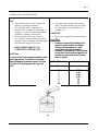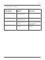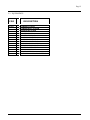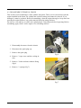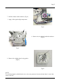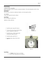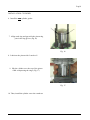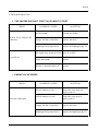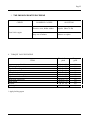
1
SNAP 100
MAINTENANCE MANUAL
All information in this publication is based the lates product information available at the time of
approval for printing.
CISCOMOTORS reserves the right to make changes at any time without notice and without
incurring any obligation.
No part of this publication may be reproduced without written permission.
Ciscomotors 2004
INDEX
Pag.2
1. OPERATING INSTRUCTIONS
Pag. 3
• 1.1 Basic operation
Pag. 4
2. SPECIFICATIONS
Pag. 6
• 2.1 Engine installation on chassis
• 2.2 Tecnicals characteristics
Pag. 6
Pag. 7
3. MAINTENANCE
Pag. 8
• 3.1 General service information
• 3.2 Routine cleaning
• 3.3 Maintenance schedule
Pag. 8
Pag. 8
Pag. 9
4. STORAGE
Pag. 10
5. SPARE PARTS & EQUIPMENT
Pag. 11
• 5.1 Spare parts
• 5.2 Equipment
Pag. 11
Pag. 12
6. ASSEMBLY/ DISASSEMBLY
Pag. 13
•
•
•
•
•
Pag. 13
Pag. 14
Pag. 20
Pag. 21
Pag. 22
6.1
6.2
6.3
6.4
6.5
Carburettor
Termical Group
Starter
Silencer
Sponge filter
7. CARBURATION REGULATIO
Pag 23
8. TROUBLESHOOTING
Pag. 24
9. TORQUE VALUES ENGINE
Pag. 25
Pag.3
1. OPERATING INSTRUCTIONS
FUEL
• Snap 100 has a two-stroke engine that
requires a gasoline-oil mixture.
• Use gasoline with a pump octane
number of 92 or higher .if “knocking” or
“pinging” occurs, try a different brand of
gasoline or a higher octane grade..
• Premix gasoline and oil in a ratio of
40:1. Prepare the fuel mixture in a clean
container fig.1 , and shake unitl throughly
mixed before filling the fuel tank.
• USE A GOOD QUALITY OF
SYNTHETIC 2-STROKE OIL
CAUTION:
To much oil will cause excessive smoking and
spark plug fouling. Too little oil will cause
engine damage or premature wear. Mix fuel
in a ratio of 40 parts gasoline to 1 part oil
(40:1)
• Vegetable oils separate from gasoline
more easily than mineral oils, especially
in cold weather. It is advisable to use
synthetic oil.
CAUTION:
• Do not mix vegetable end mineral based
oils.
WARNING
• Gasoline is extremly flamable and is
esplosive under certain conditions.
Perform this operation in a wellventilated area with the engine
stopped. Do not smoke or allow flames
or sparks in the area where gasoline is
drained or stores and where the fuel
tank is reflued.
fig.1
FUEL 92/98 octane
Sintetic oil
liters
cl
0,5
1
2
3
4
5
10
0,125
0,25
0,50
0,75
10
1,5
25
Pag. 4
1.1 BASIC OPERATION
• In the 2-stroke motors like the Snap100, is of absolute importance the corrected
carburation to avoid seizure to the piston (not covered from guarantee).
Start the Engine
WARNING
• Never run the engine in an enclosed
area. The exhaust contains poisonous
carbon monoxide gas that can cause
loss of consciousness and may lead to
death.
• Attempting to start the engine without
the riducer provokes the outbreak of
the clutch and can cause injury or
damages.
• Never run the engine in an without
propeller.
• The starter attempt can carry to the
spin of the propeller and therefore to
possible lesions.
• The motor in run emits disturbs
electromagnetic.
Warm Engine Starting:
1. To appeal the starter and to delicately
pull hardly after the harder point
2. To pull the grip with energy, without
throttle in.
Stopping The Engine
1.
Depress and hold the engine stop button
until the engine stops completely
Break-in Procedure :
Following proper break-in procedure helps
censure that some of the most important and
expensive components on your new Snap100
will provide maximum performance and service
life. (Also follow proper break-in procedure for a
newly rebuilt engine)
Cold Engine Starting:
1. Do not hold the throttle in one
position for more than a few
1. To carry in pressue the circuit of
seconds. It’s a better to roll the
the gasoline, to help itself
throttle on and off, without gain
pressing the push-button (fig.2).
too height and force too much a
2. To appeal the starter and to
motor
delicately pull hardly after the
2. Use the motor for features of 10
harder point (to try repeatedly for
minute to the time and to leave to
being sure).
cool it.
3. To pull the grip with energy,
3.
After two hours of I use or
without throttle in. .
approximately 10 liters of
4. In case of lacked starter to repeat
gasoline the motor you have
the procedure without to
ended the break.accelerate .
4.
This same procedure should be
5. Allow the engine to warm up for
followed each time
at least 2 minutes before riding
off, preferably until the side of the
• Piston is replaced
cylinder is very warm to the touch
• Cylinder is replaced
through your riding glove. Slowly
• Crankshaft or crak bearings are replaced
increase rpm and don’t blip the
trottle warning the engine is
important to prevent cold
seizures
Pag. 5
Fig.2
Pag. 6
2. SPECIFICATIONS
2.1 ENGINE INSTALLATION ON CHASSIS
Fig.3
1. Engine stop connector
2. Throttle cable
4. Support engine
5. Manual starter
CAUTION:
To use antivibrating of optimal quality not superior 70s
3. Propeller
Pag.7
2.2 TECHICALS CHARATTERISTICS
Motor SNAP 100S
Type
Disposition cylinder
Bore max
Stroke max
Displacement
Compression ratio
Maxim Power
Max Torque
Lubricating
Electrical sistem
Ignition
Rotor
Spark plug standard
Winter spark plug
Starter
Carburettor
Type
Walbro* Setting screw min
Walbro* Setting screw max
Trasmission
Clutch Type
Reduction
Reduction ratio
Exhaust
Type
Silencer
Support engine
Type
*The standard carburation
Temperature 10°c
P 1024 Mb
UR 50%
Altitude (S.L.M.) 50 m
2 times cooled to air
Monocylinder vertical
51mm
47mm
96 cc
11,2 : 1
12,5 kw (17cv) 9000 turns
14 Nm 8800 turns
20cc
Elettronic ignition
Variable Advance
Ngk br9hs
Ngk br8hs
Manual
Walbro wb32(Ciscomotors) / Dell’orto
1/4
4/5
Centrifuge 3 shoe
Gears helicoidal
1,63
Expansion Chamber
Glass wool
N.4 silent-block
Pag. 8
3. MAINTENANCE
3.1 GENERAL SERVICE INFORMATION:
• To wear gloves and glances when you make the maintenance;
• Do not perform maintenance while engine is running. Injury to your fingers, hands or head
may result ;
• Perform maintenance on firm, level ground, using hard workstand, and not directly on
chassis;
• Always install new gaskets, o-rings, piston pin clips, snap rings ect..wen riassembling
• When tightening bolts, nuts or screw, start with the larger diameter or inner fasteners, and
tighten them to the specified torque using a criss-cross pattern;
• Use genuine Ciscomotors parts when maintenance your Snap100
• Clean parts in non-flammable cleaning solvent when disassembling. Lubricate any sliding
surface, O-rings and seals before reassembling.
WARNING
Gasoline or low flash point solvents are highly flammable or explosive and must never be
used for cleaning parts . Fire or explosion could result.
• After reassembling, chek all parts for proper installation and operation
NOTE:
• Specification are listed chapter 2.
3.2 ROUTINE CLEANING
• If the SNAP100 were only little dirty to clean up it with clean dusts cloth without
dissolvents
• If the SNAP100 were much dirty to clean up it with biodegradable detergents and not with
dissolvents, lubricate where is nececessary.
Pag. 9
3.3 MAINTENANCE SCHEDULE
FREQUENCY
INSPECT
REPLACE
Before and after each use
All screw nuts, bolts correctly
tigthen, silent-block in.
Every 100 hours
Cylinder head decarbonizing
and cleaning sponge filter
Complete piston
Every 200 hours
Diameter clutch, usury of the
bell clutch, and glass wool of
the silencer
Each year
All rubber and plastic
components.
Crankshaft bearing ,bearing
reducer, oil reducer, crankshaft
seals, thermical group,
connecting rod.
Fuel diphragms of carburettor ,
spark plug.
Pag. 10
4. STORAGE
Extended storage such as for winter, requires that you take certain steps to reduce the effects of
deterioration from nonuse of your Snap100. In addition necessary repairs should be made BEFORE
storing your Snap100: otherwise these repairs and clean may be forgotten by the time your Snap100
his removed from storage.
.
Pag. 11
5. SPARE PARTS & EQUIPMENT
5.1 SPARE PARTS
COD.
DESCRIZIONE
000001.0
000002.0
000003.0
000004.0
000005.0
000006.0
000006.1
000006.2
000007.0
000008.0
000009.0
000010.0
000011.0
000012.0
000013.0
000014.0
000015.0
000016.0
000017.0
000018.0
000019.0
000020.0
000021.0
000022.0
000023.0
000024.0
000025.0
000026.0
000027.0
000028.0
000028.1
000028.2
000029.0
000030.0
000030.1
000030.2
000031.0
000032.0
000033.0
000034.0
000035.0
000036.0
000037.0
000038.0
000039.0
SPARK PLUG CUP
SHAFT SPARK PLUG
CARBON FIBER COOLING AIR DUCT
WIRE LEADS/CAP SCREW
SILENT-BLOCK MOTOR
SPARK PLUG NGK B8HS
SPARK PLUG BR8HS
SPARK PLUG NGK BR9HS
CYLINDER HEAD
CYLINDER HEAD NUTS/ WASHERS
CYLINDER HEAD SPECIAL NUTS/WASHER
NUTS/WASHERS
OR CYLINDER HEAD
CYLINDER
STUDBOLT CYLINDER
STUDBOLT EXHAUST
EXHAUST NUTS/WASHER
GLASS WOOL
PISTON COMPLETE
PISTON RING
NEEDLE BEARING
CRANKSHAFT
CONNECTING ROD
BEARING
OIL SEAL
CRANKCASE ENGINE
REED VALVE
PIPE DEPRESION CARB
THROTTLE BRACKET/CAP SCREW
MANIFOLD INTAKE WB32
MANIFOLD INTAKE TRITON
MANIFOLD INTAKE DELL’ORTO
CAP SCREW
CARBURETTOR WB32
CARBURETTOR TRITON
CARBURETTOR DELL'ORTO
FILTER BAND
CAP SCREW
FLANGE CARBURETTOR
AIRBOX
FILTER
IGNITION COIL
CAP SCREW COIL
KEY WOODRUFF
BOLT AND NUT
OPZ
OPZ
OPZ
OPZ
OPZ
OPZ
COD.
DESCRIZIONE
SCREW GRAFT STARTER
000040.0
COOLING FAN
000041.0
000042.0 OPZ PROPELLER 1250 TIPE.GT
CAP SCREW COOLING FAN
000043.0
SPRING STARTER
000044.0
GRAFT STARTER
000045.0
IGNITION COMPLETE
000046.0
IGNITION CRANKCASE COVER
000047.0
CAP SCREW
000048.0
NUT SCREW GRAFT STARTER
000049.0
MANUAL STARTER
000050.0
PULLEY STARTER
000051.0
CHORD 3,5 m/m
000052.0
HANGRIP STARTER
000053.0
SPRING MANUAL STARTER
000054.0
REDUCER
000056.0
CLUTCH
000057.0
CAP SCREW
000058.0
CAP SCREW REDUCER
000059.0
PAIR GEAR
000060.0
BEARING
000061.0
BOLT AND NUT
000062.0
CLUTCH BELL
000063.0
CRANKCASE REDUCER
000064.0
SILENT-BLOCK EXHAUST
000065.0
BOLT AND NUT
000066.0
EXAUST-PIPE EXPANSION
000067.0
SPRINGS EXHAUST
000068.0
SILENCER
000069.0
PROPELLER HUB
000070.0
RUBBER DISK
000071.0
PROPELLER FLANGE
000072.0
CAP SCREW HUB PROPELLER
000073.0
WASHERS HUB PROPELLER
000074.0
CAP SCREW
000075.0
CAP SCREWS SET CRANKCASE ENGINE
000076.0
CYLINDER GASKET
000077.0
EXHAUST GASKET
000078.0
MAINFOLD IMMISSION GASKET
000079.0
CARBURETTOR GASKET
000080.0
REDUCER GASKET
000081.0
MUFFLER BAND
000082.0
Pag.12
5.2 EQUIPMENTS
COD
100.200
100.201
100.300
100.301
100.302
100.310
100.311
100.312
100.315
100.316
100.320
100.321
100.325
100.330
DESCRIPTION
FLYWHEEL CLUTCH
FLYWHEEL BELL CLUTCH
SOCKETS HEX 17 m/m
SOCKETS HEX 11 m/m
SOCKETS HEX 10 m/m
MALE EXAGON KEY 3m/m
MALE EXAGON KEY 4m/m
MALE EXAGON KEY 5m/m
SCREWDRIVERS-BLADE 1XL
SCREWDRIVERS PHILLIPS 1-2
HUMMER PLASTIC HEAD
PLIERS FOR SPRINGS
TORQUE WRENCH
PRESSURE GAUGE CARBURETTOR
Pag.13
6. DISASSEMBLY/ASSEMBLY
WARNING
Modification of the motor, or removall of original equipment may make the motor unsafe.
6.1 DISASSEMBLY CARBURETTOR
This section covers maintenance of the carburettor.
• Repalce diaphragm fuel pump
1. Remove the 4 screw (Fig.4)
2. Remove the diaphragm
3. Clean the filter
4. To replace the diaphragm with a new
one. (Fig.5)
Fig.4
5. Install the cover and tighten the screw
to spefied torque
TORQUE: 4Nm (0.4 Kgf/m)
Fig.5
Pag.14
6.2 DISASSEMBLY TERMICAL GROUP
This section covers maintenance of the cylinder and piston. These service can be done with the
engine installed in the frame.The cylinder has a nicasil coating and cannot be rebored. If it is
demaged, it must be replaced. Before disassembling, clean the engine througly to keep dirt from
entering the engine.Remove any gasket material from the mating surfaces.
Do not use a screwdriver to remove the cylinder head. Clean all parts before inspecting. Before
assembling, apply clean 2 stroke engine oil to all sliding surfaces.
1. Disassembly the motor from the chassis
2. Disconnect the spark plug cap
3. Remove the spark plug
4. Remove 3 caps screw and the cooling air
duct
Fig.6
5. Remove 2 bolts and nuts exhausts fixing
(fig.6)
6. Remove 2 springs (Fig.7)
Fig.7
Pag.15
7. Pull the exhaust with resolution (Fig.8)
* Apply silicon gasket higt temperature.
Fig.8
8. Remove the 4 cylinder head bolts and nuts
(Fig.9)
Fig.9
9. Remove the cylinder head o-ring gasket
(Fig10)
Fig.10
NOTE
To avoid warping the cylinder head, use a criss-cross pattern to loosen each nut about ¼ turn, then
remove the nuts.
Pag.16
DISASSEMBLY PISTON
10. Remove the piston pin clips using a pair of
needle-nose pliers (Fig.11)
Fig.11
11. Press the piston pin out of the piston and
remove the piston.(Fig.12)
Fig.12
12. Spread each piston ring end remove by
lifting it up a point just oppisite the gap (Fig.13)
Fig.13
CAUTION:
do not damage the piston ring by spreading the ends too far.
Pag.17
Decarbonizing
COMBUSTION CHAMBER
Remove the carbon deposits from the combustion chamber. Clean the head gasket surface of any
gasket material
CAUTION:
Use care not to scratch the combustion chamber or the head gasket surface.
CYLINDER
Clean carbon deposits from the exhaust.
CAUTION:
Do not damage the cylinder bore.
INSTALLATION PISTON
1. Install the piston rings like (Fig.14)
2. Lubricate the piston rings and piston ring
grooves with clean 2 stroke oil
3. Install the piston with the sign turned
towards the exhaust (Fig.15)
4. Install the piston pin (Fig.12)
Fig.14
5. Install the piston rings on the piston
(Fig.11)
Fig. 15
CAUTION:
• Use new pin clips. Never use old clips
• Do not let the clips fall into the crankcase.
Pag18
INSTALLATION CYLINDER
6. Install the new cylinder gasket
7. Allign each ring and gap with the piston ring
pins in the ring groves (Fig.16)
Fig. 16
8. Lubricate the piston with 2-stroke oil
9. Slip the cylinder over the top of the piston
while compressing the rings. (Fig.17)
Fig. 17
10. Then, install the cylinder on to the crankcase
Pag. 19
INSTALLATION CYLINDER HEAD
1. Install the new cylinder head gasket o-ring (Fig.10)
2. Install the cylinder head and nuts (Fig.9 ), tighten the nuts to the specifed torque.
TORQUE : 12Nm( 1,2 kgf/m)
NOTE:
Tighten the cylinder head nuts in a criss-cross pattern in 2 or 3 steps
INSTALLATION EXHAUST
1. Insert the antivibrating pins thread in the support exhaust (Fig. 6)
2. Pull the exhaust with resolution and insert the spherical entrance on the cylinder (Fig. 8 )
3. Install the springs (Fig.7)
4. Tighten the 2 bolts and nuts to specified torque (Fig.6)
TORQUE: 10Nm( 1 kgf/m)
INSTALL COOLING AIR DUCT
1. Replace the cooling air duct on the cylinder head
2. Tighten the 2 crankcase cap screw, and then the cylinder head cap screw to the spcified
torque
TORQUE: 8Nm( 0.8 kgf/m)
INSTALLATION SPARK PLUG
1. Lubricate the sparks plug thread
2. Tigthen the spark plug to the specified torque
TORQUE : 18Nm( 1.8 kgf/m )
3. Install the spark plug cap.
Pag. 20
6.3 DISASSEMBLY/ASSEMBLY STARTER
1. Remove the air duct see the chapter 6.2
2. Remove 4 screw (Fig.18)
3. Remove the bolt (Fig.19)
4. Remove the pulley
CAUTION
NOT REMOVE THE SPRING (fig.21)
1. Install the pulley and tighten the screw
(Fig. 19) to the specified torque
TORQUE : 10Nm( 1 kgf/m)
Fig.18
2. Insert the starter into the cooling fan with
open grafts (Fig.20)
3. Tighten the screw (Fig.18) to the
specified torque
TORQUE: 6Nm( 0.6 kgf/m)
Fig.19
Fig.20
Fig.21
Pag. 21
6.4 DISASSEMBLY/ ASSEMBLY SILENCER
1. Remove the exhaust like chapter 6.2
2. Remove the 3 bolts and cap screw fixing
silencer (Fig,.22)
3. Remove the glass wool
4. Remove the carbon deposite from the
inner pipe using the wire brush
1. Repalce the glass wool
2. Install the new glass wool packing
material, opening the incision of the glass
wool
NOTE :
be carefull not to damage the glass wool
3 . Tighten the 3 bolts and cap screw to the
specified torque
TORQUE : 12Nm( 1,2 kgf/m)
Fig.22
Pag.22
6.5 DISASSEMBLY/ASSEMBLY SPONGE FILTER
1. Unscrew the filter band (fig.23)
2. Remove the airbox from the motor
3. Remove 4 screw (Fig.24)
4. Remove the sponge filter (Fig.25)
Fig.23
5. Cleaning with biodegradable detergents (don’t
use gasoline)and dry the sponge filter.
6. Lubricate the sponge filter.(Fig.25)
7. Assembly all of the airbox
CAUTION
INSTALL THE SECURITY CABLE
(fig.23)
Fig.24
Fig.25
* Foam filter , help combat the ingress of sand and dust repels water without affecting engine
breating. Only apply to clean, dry filter. Ensure complete penetration and coverage. Allow to dry
before refitting. (Fig.25)
Pag.23
7. CARBURATION REGULATION
1. Regulation throttle cable
2. Regulation Min. gasoline
3. Regulation Max gasoline
Fig.26
Standard regulation
In case of problems of wrong carburetion , repalce the originals levels.
Screw regulation of min. 1/4 turns from all closing. (Fig.26 point 2)
Screw regulation max. remove 4/5 turns from all closing. (Fig.26 point 3)
Attention the carburation regulation must be made at warm motor.
To execute in sequence the below operations:
1.
2.
3.
4.
5.
To regulate the screw of the max. to 4/5 of turn; (Fig.26 point 3)
To regulate the screw of the min. to 1/4 of turn; (Fig.26 point 2)
To fill up the circuit of feeding with the appropriate pomp;
To start the motor without accelerate (the motor must set off);
To reduce the passage holes air of the filter airbox with one hand, in order to hold the rich
carburation for some second ones;
6. To warm the motor for 4 or 5 minute to the regimen of spin of 4000 rpm;
7. To regulate the screw of the minimal jet, to put the motor to 5500 rpm, to screw or to
unscrew the screw until when the motor turns cleaned up and does not mutter;
8. To leave the motor for some second ones at minimum, to riaccelerate brusquely, now the
motor must quickly accelerate without to mumble or to come less.
Attention the turn screw is many sensitive (1/4 regulation standard)
9. To regulate the lessened motor spin de of 2000/2200 rpm. (Fig.26 point 1)
When very regulated the carburetor does not need of ulterior regulations, but in the case in
which it takes place a change of altitude (1000 meters)
Pag.24
8. TROUBLESHOOTING
1. THE ENGENE DOES NOT START OR IS HARD TO START
CHECK
Check if fuel is jetting to the
carburettor
POSSIBLE CAUSES
SOLUTION
No fuel in tank
Fill tank per fueling
Clogget fuel line or fuel filter
Replace and clean
Diaphragm fuel pomp broken
Replace the diaphragm (fig .27)
The engine stop switch is to ON Move it on OFF
Try spark test
Faulty spark plug
Replace
Broken or shorted inition coil
Replace
2. ENGINE LACHS POWER
CHECK
POSSIBLE CAUSES
SOLUTION
Fuel air mixture to lean
Tourn the screw max out
(fig.26 punto 3)
Fuel air mixture to reach
Tourn the screw max in
(fig.26 punto 3)
Clogget fuel line or fuel filter
Replace and clean
Diaphragm fuel pomp broken
Replace the diaphragm (fig.27)
Check the carburation
Pag.25
3. THE ENGINE VIBRATES EXCESSIVE
CHECK
POSSIBLE CAUSES
SOLUTION
Exessive wear, holder rubber
Repalce (Max 70 Sh)
Prop out of balance
Balance or replace
Silent-block engine
9. TORQUE VALUES ENGINE
ITEM
Cap screw propeller hub
Spark plug
Cap screw cooling air duct
Cap screw crankcase starter
Bolt cylinder head
Cap screw riducer/engine
Cap screw crankcase reducer
*Bolt Dado clutch bell
*Bolt clutch
All bolts
*Bolts ignition
* Apply locking agent
Thread diam x
pitch
Torque
gf*m
M 6 x 1,0
M14 x 1,25
M 5 x 0.8
M 5 x 0,8
M 7 x 1,0
M 6 x 1,0
M 6 x 1,0
M 10 x 1.25
M 10 x 1.25
M 6 x 1,0
M 10 x 1.25
1.2
1,8
0,6
0,6
1,2
1,1
1,2
3,8
3,8
0,9
4,0