1
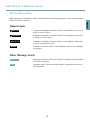
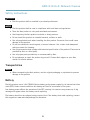
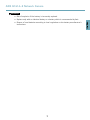
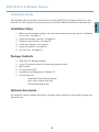
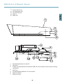
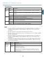
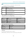
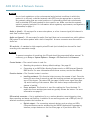
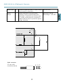
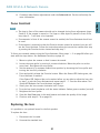
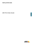
INSTALLATION GUIDE
ENGLISH
AXIS Q1614–E Network Camera
Legal Considerations
Support
Video and audio surveillance can be regulated by laws that
vary from country to country. Check the laws in your local
region before using this product for surveillance purposes.
This product includes one (1) H.264 decoder license and
one (1) AAC decoder license. To purchase further licenses,
contact your reseller.
Should you require any technical assistance, please contact
your Axis reseller. If your questions cannot be answered
immediately, your reseller will forward your queries through
the appropriate channels to ensure a rapid response. If you
are connected to the Internet, you can:
• download user documentation and software updates
• find answers to resolved problems in the FAQ database.
Search by product, category, or phrase
• report problems to Axis support staff by logging in to
your private support area
• chat with Axis support staff (selected countries only)
• visit Axis Support at www.axis.com/techsup/
Liability
Every care has been taken in the preparation of this
document. Please inform your local Axis office of any
inaccuracies or omissions. Axis Communications AB cannot
be held responsible for any technical or typographical errors
and reserves the right to make changes to the product and
manuals without prior notice. Axis Communications AB
makes no warranty of any kind with regard to the material
contained within this document, including, but not limited
to, the implied warranties of merchantability and fitness for
a particular purpose. Axis Communications AB shall not
be liable nor responsible for incidental or consequential
damages in connection with the furnishing, performance
or use of this material. This product is only to be used for
its intended purpose.
Intellectual Property Rights
Axis AB has intellectual property rights relating to
technology embodied in the product described in this
document. In particular, and without limitation, these
intellectual property rights may include one or more of the
patents listed at http://www.axis.com/patent.htm and one
or more additional patents or pending patent applications
in the US and other countries.
This product contains licensed third-party software. See
the menu item “About” in the product’s user interface for
more information.
This product contains source code copyright Apple
Computer, Inc., under the terms of Apple Public Source
License 2.0 (see http://www.opensource.apple.com/apsl).
The source code is available from
http://developer.apple.com/darwin/projects/bonjour/
Equipment Modifications
This equipment must be installed and used in
strict accordance with the instructions given in the
user documentation. This equipment contains no
user-serviceable components. Unauthorized equipment
changes or modifications will invalidate all applicable
regulatory certifications and approvals.
Trademark Acknowledgments
AXIS COMMUNICATIONS, AXIS, ETRAX, ARTPEC and VAPIX
are registered trademarks or trademark applications of Axis
AB in various jurisdictions. All other company names and
products are trademarks or registered trademarks of their
respective companies.
Apple, Boa, Apache, Bonjour, Ethernet, Internet Explorer,
Linux, Microsoft, Mozilla, Real, SMPTE, QuickTime, UNIX,
Windows, Windows Vista and WWW are registered
trademarks of the respective holders. Java and all
Java-based trademarks and logos are trademarks or
registered trademarks of Oracle and/or its affiliates.
UPnPTM is a certification mark of the UPnPTM Implementers
Corporation.
SD, SDHC and SDXC are trademarks or registered trademarks
of SD-3C, LLC in the United States, other countries or both.
Also, miniSD, microSD, miniSDHC, microSDHC, microSDXC
are all trademarks or registered trademarks of SD-3C, LLC
in the United States, other countries or both.
Learn More!
Visit Axis learning center www.axis.com/academy/ for
useful trainings, webinars, tutorials and guides.
Regulatory Information
Europe
This product complies with the applicable CE marking
directives and harmonized standards:
• Electromagnetic Compatibility (EMC) Directive
2004/108/EC. See Electromagnetic Compatibility
(EMC), on page 2 .
• Low Voltage (LVD) Directive 2006/95/EC. See Safety,
on page 3 .
• Restrictions of Hazardous Substances (RoHS) Directive
2011/65/EU. See Disposal and Recycling, on page 3 .
A copy of the original declaration of conformity may be
obtained from Axis Communications AB. See Contact
Information, on page 3 .
Electromagnetic Compatibility (EMC)
This equipment has been designed and tested to fulfill
applicable standards for:
• Radio frequency emission when installed according to
the instructions and used in its intended environment.
• Immunity to electrical and electromagnetic phenomena
when installed according to the instructions and used
in its intended environment.
USA
Using an unshielded network cable (UTP) – This
equipment has been tested using an unshielded network
cable (UTP) and found to comply with the limits for a
Class A digital device, pursuant to part 15 of the FCC Rules.
These limits are designed to provide reasonable protection
against harmful interference when the equipment is
operated in a commercial environment. This equipment
generates, uses, and can radiate radio frequency energy
and, if not installed and used in accordance with the
instruction manual, may cause harmful interference to
radio communications. Operation of this equipment in
a residential area is likely to cause harmful interference
in which case the user will be required to correct the
interference at his own expense.
Using a shielded network cable (STP) – This equipment
has also been tested using a shielded network cable (STP)
and found to comply with the limits for a Class B digital
device, pursuant to part 15 of the FCC Rules. These limits
are designed to provide reasonable protection against
harmful interference in a residential installation. This
equipment generates, uses and can radiate radio frequency
energy and, if not installed and used in accordance with
the instructions, may cause harmful interference to radio
communications. However, there is no guarantee that
interference will not occur in a particular installation. If
this equipment does cause harmful interference to radio or
television reception, which can be determined by turning
the equipment off and on, the user is encouraged to try to
correct the interference by one or more of the following
measures:
• Reorient or relocate the receiving antenna.
• Increase the separation between the equipment and
receiver.
• Connect the equipment into an outlet on a circuit
different from that to which the receiver is connected.
• Consult the dealer or an experienced radio/TV
technician for help.
Canada
This Class B digital apparatus complies with Canadian
ICES-003.
Europe
This digital equipment fulfills the requirements for RF
emission according to the Class B limit of EN 55022.
This product fulfills the requirements for emissions and
immunity according to EN 50121-4 and IEC 62236-4 railway
applications.
This product fulfills the requirements for immunity
according to EN 61000-6-1 residential, commercial and
light-industrial environments.
This product fulfills the requirements for immunity
according to EN 61000-6-2 industrial environments.
This product fulfills the requirements for immunity
according to EN 55024 office and commercial environments
Australia/New Zealand
This digital equipment fulfills the requirements for RF
emission according to the Class B limit of AS/NZS CISPR 22.
Japan
この装置は、クラスB 情報技術装置です。この装
置は、家庭環境で使用することを目 的としていま
すが、この装置がラジオやテレビジョン受信機に
近接して使用されると、 受信障害を引き起こすこ
とがあります。 取扱説明書に従って正しい取り扱
いをして下さい。
Korea
이 기기는 가정용(B급) 전자파적합기기로서 주로
가정에서 사용하는 것을 목적으로 하며, 모든 지
역에서 사용할 수 있습니다.
Safety
This product complies with IEC/EN/UL 60950-1 and
IEC/EN/UL 60950-22, Safety of Information Technology
Equipment.
Disposal and Recycling
When this product has reached the end of its useful life,
dispose of it according to local raws and regulations. For
information about your nearest designated collection point,
contact your local authority responsible for waste disposal.
In accordance with local legislation, penalties may be
applicable for incorrect disposal of this waste.
Europe
This symbol means that the product shall not be
disposed of together with household or commercial waste.
Directive 2012/19/EU on waste electrical and electronic
equipment (WEEE) is applicable in the European Union
member states. To prevent potential harm to human health
and the environment, the product must be disposed of in
an approved and environmentally safe recycling process.
For information about your nearest designated collection
point, contact your local authority responsible for waste
disposal. Businesses should contact the product supplier for
information about how to dispose of this product correctly.
This product complies with the requirements of
Directive 2011/65/EU on the restriction of the use of
certain hazardous substances in electrical and electronic
equipment (RoHS).
China
This product complies with the requirements of the
legislative act Administration on the Control of Pollution
Caused by Electronic Information Products (ACPEIP).
Contact Information
Axis Communications AB
Emdalavägen 14
223 69 Lund
Sweden
Tel: +46 46 272 18 00
Fax: +46 46 13 61 30
www.axis.com
AXIS Q1614–E Network Camera
Safety Information
Hazard Levels
DANGER
Indicates a hazardous situation which, if not avoided, will result in
death or serious injury.
WARNING
Indicates a hazardous situation which, if not avoided, could result
in death or serious injury.
CAUTION
Indicates a hazardous situation which, if not avoided, could result
in minor or moderate injury.
NOTICE
Indicates a situation which, if not avoided, could result in damage
to property.
Other Message Levels
Important
Indicates significant information which is essential for the product
to function correctly.
Note
Indicates useful information which helps in getting the most out
of the product.
5
ENGLISH
Read through this Installation Guide carefully before installing the product. Keep the Installation
Guide for future reference.
AXIS Q1614–E Network Camera
Safety Instructions
WARNING
• The Axis product shall be installed by a trained professional.
NOTICE
• The Axis product shall be used in compliance with local laws and regulations.
• Store the Axis product in a dry and ventilated environment.
• Avoid exposing the Axis product to shocks or heavy pressure.
• Do not install the product on unstable brackets, surfaces or walls.
• Use only applicable tools when installing the Axis product. Excessive force could cause
damage to the product.
• Do not use chemicals, caustic agents, or aerosol cleaners. Use a clean cloth dampened
with pure water for cleaning.
• Use only accessories that comply with technical specification of the product. These can be
provided by Axis or a third party.
• Use only spare parts provided by or recommended by Axis.
• Do not attempt to repair the product by yourself. Contact Axis support or your Axis
reseller for service matters
Transportation
NOTICE
• When transporting the Axis product, use the original packaging or equivalent to prevent
damage to the product.
Battery
The Axis product uses a 3.0 V CR2032 lithium battery as the power supply for its internal real-time
clock (RTC). Under normal conditions this battery will last for a minimum of five years.
Low battery power affects the operation of the RTC, causing it to reset at every power-up. A log
message will appear when the battery needs replacing.
The battery should not be replaced unless required, but if the battery does need replacing, contact
Axis support at www.axis.com/techsup/ for assistance.
6
AXIS Q1614–E Network Camera
WARNING
• Risk of explosion if the battery is incorrectly replaced.
• Replace only with an identical battery or a battery which is recommended by Axis.
7
ENGLISH
• Dispose of used batteries according to local regulations or the battery manufacturer's
instructions.
8
AXIS Q1614–E Network Camera
Installation Guide
Installation Steps
1. Make sure the package contents, tools and other materials necessary for the installation
are in order. See page 9 .
2. Study the hardware overview. See page 10.
3. Study the specifications. See page 16.
4. Install the hardware. See page 18.
5. Access the product. See page 20.
6. Set the focus. See page 20.
Package Contents
•
•
•
•
•
•
AXIS Q1614–E Network Camera
4–pin I/O connector block for connecting external devices
Wall bracket
Torx screwdriver T20
Installation and Management Software CD
Printed materials
Installation Guide (this document)
Extra serial number label (2x)
AVHS Authentication key
Optional Accessories
For information about available accessories, including power accessories and outdoor housings see
www.axis.com
9
ENGLISH
This Installation Guide provides instructions for installing AXIS Q1614-E Network Camera on your
network. For other aspects of using the product, see the User Manual available at www.axis.com
AXIS Q1614–E Network Camera
Hardware Overview
1
2
3
10
4
5
1.
2.
3.
4.
5.
6.
7.
8.
9.
10.
6
7
8
9
11 12 13 14 15
Status LED indicator
Zoom puller
Focus puller
I/O connector
Iris connector
Power connector
Power LED indicator
Network LED indicator
RS485/RS422 connector
Network connector (PoE)
10
AXIS Q1614–E Network Camera
Control button (1)
Function button (2)
microSD Card slot
Audio in
Audio out
ENGLISH
11.
12.
13.
14.
15.
1
2
3
4
5
6
7
15
1.
2.
3.
4.
5.
6.
7.
14
13 12
10
11
8
9
Sunshield adjustment screw (2x)
Sunshield
Product number (P/N) & Serial number (S/N). The serial number may be required during
installation.
Top Cover
De-humidifying membrane. Do not remove!
Network camera
Safety wire tab
11
AXIS Q1614–E Network Camera
8.
9.
10.
11.
12.
13.
14.
15.
Cable holes with cable gland
Bottom cover screws (4x)
Cable cover
Cable cover screws (2x)
Network connector
Bottom cover
Heater. Caution! May be hot.
Heater. Caution! May be hot.
1
2
3
4
1.
2.
3.
4.
5.
Network cable (route through wall bracket)
Bottom cover
Bottom cover screws (4x)
Bracket adjustment screw
Wall bracket
12
5
AXIS Q1614–E Network Camera
LED Indicators
Color
Indication
Network
Green
Steady for connection to a 100 MBit/s network. Flashes for network
activity.
Amber
Steady for connection to a 10 MBit/s network. Flashes for network
activity.
Unlit
No network connection.
Green
Steady green for normal operation.
Amber
Steady during startup and when restoring settings.
Red
Slow flash for failed upgrade.
Green
Normal operation.
Amber
Flashes green/amber during firmware upgrade.
Status
Power
Note
• The Status LED can be configured to be unlit during normal operation. To configure, go
to Setup > System Options > Ports & Devices > LED. See the online help for more
information.
• The Status LED can be configured to flash while an event is active.
• The Status LED can be configured to flash for identifying the unit. Go to Setup > System
Options > Maintenance .
• The Power LED can be configured to be unlit during normal operation. To configure, go
to Setup > System Options > Ports & Devices > LED. See the online help for more
information.
• The Network LED can be disabled so that it does not flash when there is network traffic.
To configure, go to Setup > System Options > Ports & Devices > LED. See the online
help for more information.
LED
Color
Indication
Housing
(fan and
heater)
Green
Normal operation.
Flashing
green
Single flash: Heater error
Double flash: Fan error
Triple flash: General error
Alarm events will be triggered through the camera’s input port.
Contact your Axis reseller for information about spare parts and
troubleshooting.
13
ENGLISH
LED
AXIS Q1614–E Network Camera
Note
This status LED referred to in the table above is located in the housing.
Status LED Behavior for Focus Assistant
Color
Indication
Green
Focus Assistant is enabled
The lens is optimally adjusted
Amber
The camera has been moved, or an object has been inserted in front of the lens.
Exit and restart the Focus Assistant.
The lens is less optimally adjusted.
Red
The camera has been moved, or an object has been inserted in front of the lens.
Exit and restart the Focus Assistant.
The lens is poorly adjusted.
Status LED Behavior for Levelling Camera
For information on the Function button used for levelling the camera, see Connectors.
Color
Buzzer
Camera position
Fixed green
Continuous beep
Level
Flashing green
Fast interval
Almost level
Flashing orange
Medium interval
Not level
Flashing red
Slow interval
Far from level
Buzzer Signal while Levelling Camera
Buzzer
Camera position
Fast interval
Almost level
Medium interval
Not level
Slow interval
Far from level
Connectors
For specifications and operating conditions, see page 16.
Network connector - RJ45 Ethernet connector. Supports Power over Ethernet (PoE).
14
AXIS Q1614–E Network Camera
NOTICE
Audio in (pink) - 3.5 mm input for a mono microphone, or a line-in mono signal (left channel is
used from a stereo signal).
Audio out (green) - 3.5 mm output for audio (line level) that can be connected to a public address
(PA) system or an active speaker with a built-in amplifier. A stereo connector must be used for
audio out.
SD card slot - A standard or high-capacity microSD card (not included) can be used for local
recording with removable storage.
NOTICE
To prevent corruption of recordings, the SD card should be unmounted before removal. To
unmount, go to Setup > System Options > Storage > SD Card and click Unmount.
Control button - The control button is used for:
•
•
Resetting the product to factory default settings. See page 22.
Connecting to an AXIS Video Hosting System service or AXIS Internet Dynamic
DNS Service. For more information about these services, see the User Manual.
Function button - The Function button is used as:
•
•
Levelling assistant : This function helps to ensure the camera is level. Press the
button for more than 2 seconds to start the levelling assistant and press again to
turn off the buzzer. The status LED (see page 14) and buzzer signal (see page
14) assist levelling of the camera. When the buzzer beeps continuously the
camera is levelled.
Focus assistant: This function is used for enabling the Focus Assistant. To
enable the focus assistant press and very quickly release the button. For more
information see page 21.
I/O terminal connector - Use in applications for e.g. motion detection, event triggering, time
lapse recording and alarm notifications. In addition to an auxiliary power and a GND pin, the I/O
terminal connector provides the interface to:
•
Digital output – For connecting external devices such as relays and LEDs.
Connected devices can be activated by the VAPIX® Application Programming
Interface, output buttons on the Live View page or by an Action Rule. The
15
ENGLISH
Due to local regulations or the environmental and electrical conditions in which the
product is to be used, a shielded network cable (STP) may be appropriate or required.
Any network cables that are routed outdoors or in demanding electrical environments
shall be shielded (STP) and intended for their specific use. Make sure that the network
switch is properly grounded. For information about regulatory requirements, see Regulatory
Information, on page 2 .
AXIS Q1614–E Network Camera
output will show as active (shown under System Options > Ports & Devices) if
the alarm device is activated.
Digital input – An alarm input for connecting devices that can toggle between
an open and closed circuit, for example: PIRs, door/window contacts, glass
break detectors, etc. When a signal is received the state changes and the input
becomes active (shown under System Options > Ports & Devices).
•
Note
The I/O connector is connected to the housing (fan/heater) on delivery, and will trigger an
input port event to indicate a fan or heater error when activated. See for information
about events.
RS485/RS422 connector - Two 2-pin terminal blocks for RS485/RS422 serial interface used to
control auxiliary equipment, e.g. PTZ devices.
Specifications
Product
Temperature
Humidity
AXIS Q1614–E
–30 °C to 50 °C
(–22 °F to 122 °F)
with PoE; down to
–40 °C (– 40 °F with
High PoE
20-85% RH (non-condensing)
Connectors
I/O terminal connector
4–pin terminal block for:
• Digital Input
• Digital Output
• Auxiliary power and ground
(GND)
Function
Pin
Notes
GND
1
Ground
12V DC
Power
2
Can be used to power auxiliary equipment.
Note: This pin can only be used as power out.
Specifications
16
Max load = 15 mA
AXIS Q1614–E Network Camera
3
Connect to GND to activate, or leave floating
(unconnected) to deactivate.
0 to +30 V DC
Digital
Output
4
Internal connection to ground when
activated, floating (unconnected) when
deactivated. If used with an inductive load,
e.g. a relay, a diode must be connected in
parallel with the load, for protection against
voltage transients.
Max load =100 mA
Max voltage = +30 V DC
1
12 V max 15 mA
2
3
4
Audio connector
3.5 mm audio
connectors (stereo)
3
17
2
1
ENGLISH
Digital Input
AXIS Q1614–E Network Camera
Audio Input
Audio Output
1 Tip
Balanced Microphone Hot (+)
In/Unbalance Microphone In/Line In
Line out (mono)
2 Ring
Balanced Microphone Cold (-) In
3 Sleeve
Ground
Ground
RS485/422 connector
Two 2-pin terminal blocks for RS485/RS422 serial
interface. The serial port can be configured to support:
•
•
•
•
Two-wire RS485 half duplex
Four-wire RS485 full duplex
Two-wire RS422 simplex
Four-wire RS422 full duplex point to point
communication
RX/TX TX
1 2
3 4
Function
Pin
Notes
RS485/RS422 RX/TX A
1
RS485/RS422 RX/TX B
2
(RX) For full duplex RS485/RS422
(RX/TX) For half duplex RS485
RS485/RS422 TX A
3
RS485/RS422 TX B
4
(TX) For full duplex RS485/RS422
Install the Hardware
Do the following to install the wall bracket:
18
AXIS Q1614–E Network Camera
Note
• The weight of the camera is 3525 g (7.7 lb). Check that the material is strong enough to
support this weight.
• Always use a shielded network cable (STP) intended for outdoor use between the
Axis product and the end point and ensure that the end point is properly grounded.
Installations of Axis products using a shielded network cable (STP) and a properly
grounded end point have been tested to comply with industry immunity standard levels
such as surge protection. Any other installation method will void the warranty and
leave the unit at a risk.
• An optional cable with a diameter of 4.0 mm - 5.5 mm should be routed through a
separate cable gland. See Hardware Overview, on page 10.
1. Use the supplied drill template to prepare a wall or pole for installation of the wall
bracket.
2. Route the network cable through the wall bracket, and through the bracket adapter.
Leave approximately 30 cm (11.8”) of cable for connecting to the camera.
3. Install the wall bracket on a wall, ceiling, or pole using screws and plugs appropriate for
the material (e.g. wood, metal, sheet rock, stone).
Do the following to route the network and other (optional) cables:
1. Loosen the cable cover screws; detach the cable cover from the bottom cover.
2. Remove the cap, the plug and the gasket from the cable gland to be used.
3. Route the network cable through the cap.
4. Slide the network cable through the slit in the gasket.
5. Route the network cable through the cable gland.
6. Press the gasket into the cable gland and screw the cap on firmly.
Do the following to attach the camera to the wall bracket
1. Place the camera with the bottom cover on the wall bracket and tighten the bracket
screws.
2. Replace the cable cover and tighten the screws.
3. Connect the cables. See Connect the Cables, on page 20.
4. Loosen the bracket adjustment screw to focus the camera; focus the camera according
to the instructions under Adjust Focus, on page 20.
5. Also see Access the Product, on page 20 to access the video stream.
6. Attach the safety wire in the top cover to the tab in the bottom cover. See image under
Hardware Overview, on page 10.
19
ENGLISH
• Using any other than the provided cable gland may cause water to seep in and damage
the product.
AXIS Q1614–E Network Camera
7. Optionally insert an SD memory card (not included) into the SDHC (Secure Digital High
Capacity) card slot. A standard or high capacity SD card is required to store images
locally in the camera.
Connect the Cables
1. Optionally connect external input/output devices. See Connectors, on page 16.
2. Connect the network cable to the network connector in the housing.
NOTICE
Due to local regulations or the environmental and electrical conditions in which the
product is to be used, a shielded network cable (STP) may be appropriate or required. Any
network cables that are routed outdoors or in demanding electrical environments shall be
shielded (STP) and intended for their specific use.
Access the Product
Use the tools provided on the Installation and Management Software CD to assign an IP address,
set the password and access the video stream. This information is also available from the support
pages on www.axis.com/techsup/
Adjust Focus
To adjust the zoom and focus follow these instructions:
Note
• Set focus as precisely as possible with the focus puller or Focus Assistant before starting
automatic fine tuning. Using the focus puller normally gives the best result.
• The iris should always be opened to its maximum while focusing. This gives the smallest
depth of field and thus the best conditions for correct focusing.
Open the product’s home page and go to Setup > Basic Setup > Focus.
Under the Basic tab, click Open iris. If the button is inactive the iris is already open.
If focus has been set before, click Reset to reset the back focus.
Loosen the zoom and focus pullers (see Hardware Overview, on page 10) on the lens by
turning them counter-clockwise. Move the pullers to set zoom and focus and check
the quality of the image in the image window. If the camera is mounted so that one
cannot look at the image and move the pullers at the same time, use the Focus Assistant
instead. See Focus Assistant, on page 21.
5. Re-tighten the zoom and focus pullers.
6. On the Focus page, click Fine-tune focus automatically and wait until automatic fine
tuning is completed.
7. Click Enable iris. If the button is inactive the iris is already enabled.
1.
2.
3.
4.
20
AXIS Q1614–E Network Camera
8. If needed, make further adjustments under the Advanced tab. See the online help for
more information.
Note
• The view in front of the camera should not be changed during focus adjustment (steps
5 and 6). If the camera is moved, or if a finger or other object is placed in front of the
lens, steps 3 - 7 will have to be repeated.
• If movements in front of the camera cannot be avoided, the Focus Assistant should not
be used.
• If the camera is mounted so that the Function button cannot be accessed, you can still
use the Focus Assistant. Follow the instructions above but mount the camera after step
4, pressing the Function button instead and skip step 7.
To focus your network camera using the Focus Assistant, follow steps 1 - 3 on page 20 before you
start with the steps below. See Hardware Overview, on page 10.
1. Mount or place the camera so that it cannot be moved.
2. Loosen the zoom puller by turning it counter-clockwise. Move the puller to set the
zoom level. Re-tighten the zoom puller.
3. Set the camera to its extreme distant-focus position by loosening the focus puller and
turning the lens fully clockwise.
4. Press and quickly release the Function button. When the Status LED flashes green, the
Focus Assistant is enabled.
If the Status LED flashes either red or amber before you are able to adjust the lens, skip
to step 7 to exit the Focus Assistant and repeat steps 3 - 7. See the notes above. See
Status LED Behavior for Focus Assistant, on page 14.
5. Gently turn the lens counter-clockwise until it stops.
6. Turn the lens slowly clockwise until the status indicator flashes green or amber (not red).
7. Retighten the focus puller.
8. Open the Live View page in the web browser and check the quality of the image.
9. Continue with steps 6 - 8 on page 20.
Replacing the lens
It is possible to use optional lenses for the Axis product.
To replace the lens:
1. Disconnect the iris cable.
2. Unscrew the standard lens.
21
ENGLISH
Focus Assistant
AXIS Q1614–E Network Camera
3. Attach and screw on the new lens.
Reset to Factory Default Settings
Important
Reset to factory default should be used with caution. A reset to factory default will reset
all settings, including the IP address, to the factory default values.
To reset the product to the factory default settings:
1. Disconnect power from the product.
2. Press and hold the control button and reconnect power. See Hardware Overview, on
page 10.
3. Keep the control button pressed for about 15–30 seconds until the status LED indicator
flashes amber.
4. Release the control button. The process is complete when the status LED indicator turns
green. The product has been reset to the factory default settings. If no DHCP server is
available on the network, the default IP address is 192.168.0.90
5. Use the tools provided on the Installation and Management Software CD to assign an IP
address, set the password and access the video stream. This information is also available
from the support pages on www.axis.com/techsup
6. Refocus the product.
It is also possible to reset parameters to factory default via the web interface. Go to Setup
> System Options > Maintenance.
Further Information
The User Manual is available at www.axis.com
Visit www.axis.com/techsup to check if there is updated firmware available for your network
product. To see the currently installed firmware version, go to Setup > About.
Visit Axis learning center www.axis.com/academy for useful trainings, webinars, tutorials and
guides.
Warranty Information
For information about Axis’ product warranty and thereto related information, see
www.axis.com/warranty/
22
23
Installation Guide
AXIS Q1614–E Network Camera
© Axis Communications AB, 2013
Ver. M2.2
Date: October 2013
Part No. 52622