1
BOSCH
Quick Reference Index
Installation
Instructions
for SHU (9900, 6800, 5300, 4300,
4000, 3300, 3030)
and SHI (6800, 4300)
and SHV (4800, 4300)
INTRODUCTION
TOOLS NEEDED FOR INSTALLATION
MATERIALS YOU WILL NEED
ACCESSORY PARTS SUPPLIED
2
2
2
2
TECHNICAL DATA
CHOOSING THE LOCATION
PREPARING
THE LOCATION
HOT WATER SUPPLY
DRAIN HOSE
ELECTRICAL
SUPPLY
4
4
4
4
INSPECTING THE DISHWASHER
PLACING THE DISHWASHER
DRAIN HOSE
CONNECTING HOT WATER SUPPLY
CONNECTING ELECTRICAL SUPPLY
GROUNDING INSTRUCTIONS
PANEL INSTALLATION, SHI MODELS
PANEL INSTALLATION, SHV MODELS
ACCESSORY PANEL INSTALLATION, SHU
I
7
8
8
8-9
9
9
DOOR TENSION ADJUSTMENT
10
FINAL CHECK LIST
10
I
IMPORTANT: Before you begin read these instructions completely and carefully.
INSTALLER:
Please leave this manual with owner for future reference.
OWNER: Save these installation instructions for local electrical
inspector's
6-7
use and for future reference.
Introduction
Please read these installation instructions completely
and carefully. They will save you time and effort and
help to ensure optimum dishwasher performance.
sure to observe all listed warnings and cautions.
Be
These installation instructions are intended for use by
qualified installers. In addition to these instructions the
dishwasher shall be installed:
* In the United States, in accordance with the
National Electric Code/State
and/or local codes.
•
and Municipal
O
codes
In Canada, in accordance with the Canadian
Code C22.1 - latest edition/Provincial
and
Electric
Municipal codes and/or local codes.
These shall be carefully followed at all times.
If the dishwasher
is a new installation
most of the work
must be done before the dishwasher is moved into place.
If the dishwasher is replacing another dishwasher the
connections for the dishwasher being replaced must be
checked for compatibility
with the new dishwasher and
replaced as necessary.
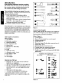
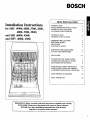
Tools Needed
Refer to Figure 1:
A. Tape Measure
B. Flat blade screwdriver
Phillips screwdriver
Torx screwdriver, #20
Electric Drill
E
G.
H.
Hole saw or 1" hole cutter
Hammer
Level
I.
Open end wrench
Figure
1.
Accessory Parts Supplied
Check to make sure that the accessory
parts supplied
your model, see Figure 2, are all there. If any parts are
missing contact your dealer immediately.
E
R.
S.
Screws (2), for terminal
Mounting brackets (2)
Wood screws (2)
box cover/toe
panel
T.
U.
V.
Drain hose clamps (2) with rubber connection
Screws, M6 x 26 (2)
Mounting brackets (4) and screws (8)
Accessory parts supplied with:
SHU models
SHI and SHV models
M. Wire stripper
_-C_
O__
You Will Need
•
Minimum 3/8" O.D. copper
length for your installation.
•
•
Shut-off valve and fittings for hot water supply line.
90 ° elbow with 3/8" N.P.T. external threads on one
tubing of sufficient
end and sized to fit your water supply line on the
other end.
•
•
•
Teflon tape or other pipe sealant.
3 twist-on wire connectors for 16 AWG wire.
UL listed conduit connector or strain relief.
Additional materials may be required to comply with
local codes.
0-44
2
hose (1)
W. Template sheet with instruction pictograms.
X. Screws, M4 x 42 (2) (SHV models only)
Y. Handle Installation Kit with Instructions
(SHU 9900
models only)
J. Adjustable wrench, 2 reqd.
K. Pipe wrench, 2 reqd.
L. Wire Cutter
Materials
for
Refer to Figure 2:
O. Cover Plugs (2)
for Installation
C.
D.
E.
)
Figure 2.
_
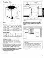
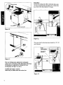
Technical Data
22-7/16'
(570 mm
I\
<
23-s/8' - 24' (600- 610 ram)
1-15/16"
(49mm)
Figure
4.
If the dishwasher
Figure 3.
is to be installed
sure there is adequate
Figure 5.
Dimensions
A
height
33-7/8" - 35"
B
width
23-9/16"
clearance
in a comer,
make
to open the door. See
(860 - 890 mm)
(598 mm)
Clearance
T
for door openingT
C
Electrical
depth
22-7/16
(570 ram)
Door in
Rating
Volts
Hertz
120
60
Dishwasher
openPosition
Amperes
12
Watts
1,450 (max)
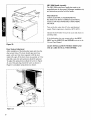
Choosing the Location
Most of the installation work is done before the
dishwasher is moved into place. Select a location as
close to the sink as possible for ready access to water
and drain lines.
Any built-in dishwasher must be fully enclosed on the
top, both sides and back. Therefore the cabinet space
below your counter is probably the best location.
For proper operation and appearance of the dishwasher,
the cabinet opening should be square and have
dimensions as shown in Figure 4.
Countertop
1
Figure 5.
CAUTION:
To protect against possible rupture of the fill valve,
water lines leading to the dishwasher, as well as
water lines in the dishwasher MUST be protected
against freezing. If the valve or water line freezes,
flooding may occur. Such ruptures are not covered
by the warranty.
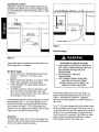
Preparing
the Location
Openings for electrical, water and drain lines must be
installed in the marked area as shown in Figures 6 and 7
to avoid interference with the dishwasher frame or other
components.
Shut-off
valve
!
I
I
I
I
/_
\
(520 ram)
23-5/8"- 24"
(600 - 610 rnm)
3-1/2'
Hot watersupplyline _
,(90 mm)
)_
1-15/16.
Figure
7.
Electrical
Supply
Figure 6.
Access holes must be rounded
and smooth.
Holes must
not be larger than I'A" diameter.
Hot Water
•
•
ELECTRICAL
•
Supply
The hot water line to the dishwasher must provide
between 5 - 120 psi (0.3 - 8.27 bars) water
pressure.
The hot water heater should be set to deliver 140°F
(60°C) water temperature
to the dishwasher.
•
A 3/8" minimum
recommended.
O.D. copper tubing inlet line is
•
All solder connections must be made before water
line is connected to the dishwasher's
inlet water
valve. Do not solder within 6 inches
the dishwasher's
inlet water valve.
(152.4 mm) of
After determining
where the water supply line will enter
the dishwasher, drill a 1" (25.4 mm) diameter access
hole and run the line to the approximate fill valve location, as shown in Figure 7. It is recommended
that a
shut-off valve (not supplied) be installed in the hot water
supply line in a readily accessible location.
•
•
SHOCK
HAZARD
DISCONNECT
ELECTRICAL
POWER AT
THE CIRCUIT BREAKER BOX OR FUSE
BOX BEFORE INSTALLING THE
DISHWASHER.
ELECTRICALLY
GROUND
DISHWASHER.
USE COPPER CONDUCTORS
ONLY.
FAILURE TO FOLLOW THESE
INSTRUCTIONS
COULD RESULT IN
SERIOUS INJURY OR DEATH.
The electrical supply must be 120 volt, 60 Hz, 12
ampere, properly grounded, positioned as shown in
Figure 7, and should be installed by a qualified
electrician. No other appliances or outlets should be on
this circuit.
Cut a I" (25.4 mm) diameter
hole in the cabinet
for the
electrical wiring to pass through. If this hole is cut in a
wood cabinet, the hole should be sanded until smooth. If
the hole is cut in a metal cabinet, the edge of the hole
must be covered by a grommet. Run flexible, as codes
Drain Hose
The dishwasher comes with a seven (7) foot drain hose.
An access hole must be made to allow the drain hose to
be run to the drain connection location.
4
permit, cable from junction through hole in cabinet.
Cable should extend 30" from back wall.
Inspecting the Dishwasher
After unpacking the dishwasher and prior to installation
thoroughly inspect the dishwasher for possible freight or
cosmetic damage. Report any damage immediately.
Cosmetic damage must be reported within 5 days of
installation.
Mounting bracket bent
lot mounting to side of cabinet
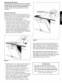
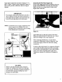
Placing the Dishwasher
The profile strips on the sides of the dishwasher allow
the dishwasher to fit into a cabinet opening with a width
of 23-5/8" (600 ram) to 24" (610 mm). Before sliding
the dishwasher
into the cabinet opening:
I. Determine how the mounting brackets will be
placed. The brackets may be placed so as to fasten to
the underside of the counter top, in Figure 8, or, the
brackets may be bent and set to fasten to the side of
the cabinet opening as, Figure 9. The dishwasher
should be mounted to the side of the cabinet if there
is a granite, marble or other hard natural surface
counter top that could be damaged by drilling. Once
decided, set the mounting brackets before sliding the
dishwasher into place, see Figure 10.
Figure 9.
Once slid into place make final leveling adjustments as
shown in Figure 1 I. Then to maintain the dishwasher
position and alignment, drive 2 wood screws through the
holes in the mounting flanges that had been placed at
each of the front comers, as shown in Figures 8 and 9.
Once the dishwasher
has been leveled
and secured
in
place proceed to the connection of the drain hose, hot
water supply line and electrical connections as described
in the following sections. Be sure to follow your
national and local codes at all times.
Figure 8.
2. Straighten the hot water supply line and the electrical
cable so that it can be easily pulled through the
channel imder the dishwasher. See Figure 10.
3. Guide the drain hose carefully as the dishwasher
is
slid into the cabinet opening so that there are
no kinks in the hose once the dishwasher is in place.
4. All necessary tinal leveling and alignment
adjustments can be made after sliding the dishwasher
into the cabinet opening. It is however recommended
that the adjustments be made before sliding the
dishwasher
into opening and then any final line
adjustments made after the dishwasher is in place.
IMPORTANT
If you wish to change the front panel of the
dishwasher this must be done before sliding the
dishwasher
into place. See section in this manual
titled Accessory Panel Installation,
SHU Models.
*Note:
Additional accessory door panels can not
be used with SHU 9900 models.
Drain Hose
Use the hose clamp and rubber connection hose, item
"T" from accessory parts (see figure 2) to connect the
drain hose to the sink, disposer or air gap.
Hotwaterline
lectric supplycable
Figure
10.
Figure
12.
The access hole for the drain hose should be 1.25" (32
mm) diameter.
Airgap
Rubberconnector
Entry mustbe
abovetrap
H_re
11.
The rear leveling leg is adjusted by turning the
center screw at the front of the dishwasher. The front
leveling
leveling
legs are adjusted by rotating
legs. See figure 11, above.
If additional height is needed:
Shims may be added under the leveler
the front
feet.
Figure 13.
6
f
Typical drain connections are shown in figures 12, 13
and 14. Figure 12 shows typical connection. Figures 13
and 14 show possible connections when an air gap is
required.
Connecting
the Hot Water
Supply Line
The hot water supply line should be flushed to clear any
foreign matefiai BEFORE connecting the dishwasher.
Make sure there are no sharp bends or kinks which
might restrict water flow.
IMPORTANT
If no air gap is used and the drain line is run into a
sink or disposer, the drain line must be elevated to a
point higher than the highest water level of the sink
to prevent back siphoning into the dishwasher.
NOTE:
If connection to an air gap is required by local
code, air gap kits are available from local
plumbing sources. Install the air gap according
to the manufacturer's
instructions.
Figure 15.
Airgap
Rubber
connector
("
Entry
must be
Apply Teflon tape or other pipe sealant to 90 ° elbow
fitting and connect directly to water inlet valve. Attach
other end of fitting to your water supply line.
When connecting threaded pipe use pipe thread
compound or Teflon tape to seal the connection. Turn
on the water supply to check for leaks after making
connections.
If using a solder joint instead of a compression
fitting be
sure to make all solder connections before connecting
the water line to the dishwasher. Do not solder within 6
inches (152.4 mm) of the dishwasher's
inlet valve.
Temperatures
required for soldering will damage the
valve.
Figure ! 4 .
CAUTION
Failure to provide the proper drain connection
height, 20" (508mm) above floor level with high
loop or air gap, will result in improper draining of
the dishwasher. Improper draining may cause
damage to the dishwasher.
Connecting
the Electrical Supply
The electrical supply must be 120 volt, 60 Hz, 12
ampere, properly grounded. Connect with copper wire
only.
•
•
•
ELECTRICAL
SHOCK HAZARD
DISCONNECT
ELECTRICAL
POWER AT
THE CIRCUIT BREAKER BOX OR FUSE
BOX BEFORE INSTALLING
THE
DISHWASHER.
ELECTRICALLY
GROUND
DISHWASHER.
USE COPPER CONDUCTORS
ONLY.
FAILURE TO FOLLOW THESE
INSTRUCTIONS
COULD RESULT
SERIOUS INJURY OR DEATH.
Grounding
IN
Instructions
This appliance must be connected to a grounded metal
permanent wiring system; or an equipment grounding
conductor must be run with the circuit conductors and
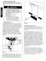
Figure
Panel
17.
Installation,
SHI Models
connected to the equipment grounding terminal or lead
on the dishwasher. The dishwasher must be properly
If you have an SHI model, an integrated model, you will
have additional mounting hardware and a folded
grounded before operating. Make sure that the
dishwasher is connected to a suitable ground in
compliance with the NATIONAL ELECTRICAL
CODE, in the United States, or the CANADIAN
ELECTRIC CODE C22. l-latest edition, in Canada
template sheet with installation
of pictograms.
well as any provincial/state
that apply.
or municipal
In North America
as
or local codes
Black wires
Green or
bare wires
U.L listed
conduit
CONR_ctor
instructions
comprised
the black, white and stainless
steel
models of the integrated series (SHI series), have a
control panel that is 5-5/16" (135 ram) tall. The black
and white models come with a standard extension piece,
dimension "A" in figure 18 and table 1, below. The
stainless steel model comes with two extension pieces,
referred to as the standard and long extension piece in
1hble 1: the standard piece is used for drawer heights
up to 6" (152ram); the long extension piece is used for
drawer heights greater than 6" (152ram) but 6-7/16"
(164ram) or less. These stainless steel extension pieces
are not installed in the control panel. Rather the stainless
steel models ship the two extension pieces loose and
must be inserted as shown in pictogram 5 on the
template sheet.
The purpose of the extension piece is to allow the
increase of the control panel height to try to match the
horizontal drawer line of the cabinets. If your drawers
are taller than the "C'" dimension shown on Table 1 it is
recommended
that the extension either be slid in as far
Figure
16.
After completing wiring and testing, be sure that wires
are pressed back into the terminal box and then securely
fasten the terminal box cover/toe panel in place using
screws from accessory package. See Figures 2 and 17.
as it will go, or removed and the door made to fit
directly below the control panel.
Panel Installation,
SHV Models
If you have an SHV model, a fully integrated model,
you will have additional mounting hardware and a folded
template sheet with installation instructions comprised
of pictograms.
Refer to the folded template sheet for information on
how to mount the panel. Please note that one side of the
template shows how to mount a one piece panel and the
other side of the template shows how to mount a two
piece panel. Be sure of what type installation you want
before proceeding with the installation.
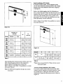
Refer to Figure 19 and Table 2 for guidelines
door panel selections.
Figure
on custom
18.
Extension
"A"
maxJmin.
"B"
Model
Standard
SHI
6802
(21 / 0 mm)
SHI
6806
(21 / 0 mm)
SHI
4302
(21 / 0 ram)
SHI
4306
SHI
6805
maxdmin
Long
13/16" / 0"
D
E
5-5/16"
6-1/8" / 5-5/16"
-
(135ram)
(156 / 135 mm
5-5/16"
6-1/8" / 5-5116"
- - -
(135mm)
5-5116"
6-1/8" / 5-5/16"
--
-
(135ram)
(156 / 135 mm
5-5/16"
6-118" / 5-5116"
(21 / 0 ram)
- - -
(135mm)
(156 / 135 mm
Model
D
11116"15116"
1-118"111116"
5-5/16"
6-7116" / 5-5/8"
SI-IV
NA
(18/8
(29/18
(135ram)
(164 / 143 mm
27-3116" - 30-5116"
(690 - 770 mm)
23-3116" - 23-3/8"
(589 - 594 mm)
SHI
20-11/16" - 25"
27-3/16" - 30-5/16"
23-3/16" - 23-3/8"
(526 - 635 mm)
(690 - 770 mm)
(589 - 594 mrn)
-
13116" / 0"
13/16" / 0"
13116" / 0"
ram)
mm)
(156/135
mm
Figure
19.
Table 1.
After deciding if the extension pieces will be used or not
refer to the pictograms printed on the template for
proper method of mounting your custom door.
Refer to Figure 19 and Table 2 for guidelines on custom
door panel selection.
Note: Do NOT Drill Completely
door panel.
through
your custom
Table
* E
F
2.
*Note: Do not exceed 30 5/16 (770mm)
front panel length.
for the overall
Accessory Panel Installation,
SHU Models
If you have an SHU model (other than the SHU 9900
models) and have ordered an accessory panel kit it must
be installed prior to sliding the dishwasher into place.
Dimensions of panel size that may be used is shown in
Figure 20.
SHU 9900 Handle Assembly
The SHU 9900 model has a handle that needs to be
1/4" max.
(6mm)
assembled onto the door panel. Reference installation
and instructions provided with the handle.
kit
Final check list
CHECK ELECTRICAL
REQUIREMENTS.
BE SURE YOU HAVE CORRECT ELECTRICAL
SUPPLY AND RECOMMENDED
GROUNDING
METHOD.
(586 mm'
Turn on the hot water shut-off
supply. Water temperature
Operate the dishwasher
plumbing leaks.
valve and electrical
should be 140°F (60°C).
through one cycle and check for
If the dishwasher does not operate refer to the SELFHELP and the SERVICE and REPAIR sections in the
Use and Care Manual.
Figure 20.
LEAVE INSTALLATION
USE & CARE MANUAL
Door Tension Adjustment
After installation of the dishwasher open and close the
door several times. The door should open and close
easily with very little force required to lift the door
when fully open. If the door closes too quickly, or if the
door falls open, the spring tension should be adjusted.
To adjust the spring tension obtain the screw in Figure
21 out of the parts bag. Insert the screw as shown in
Figure 21 and adjust spring tension as shown.
lTorxT20 ].
Figure 21.
10
INSTRUCTIONS
WITH OWNER.
AND
56 02 03 6207 (7910)