1
KEYBOARD
KLAVIATŪRA
EKB3
INSTALLATION MANUAL
EKB3 is a keyboard intended to use with GSM alarm and management system ESIM264.
Main EKB3 keyboard functions are:
•
arm and disarm security system
•
arm and disarm STAY mode
•
configure system parameters
•
display information with LED indicators
•
inform about system status via sound signaler
The keyboard uses two password levels - user and administrator. System configuration can be performed by entering administrator
password and using programing commands. ESIM264 allows to connect up to 4 EKB3 keyboards. Integrated sound signaler informs
about successful/unsuccessful functions performance, informs about entry and delay time countdowns.
CONTENT
1. Package content................................................................................................................................................................. x
2. Device installation.............................................................................................................................................................. x
3. Technical specifications...................................................................................................................................................... x.
3.1 Electrical and mechanical characteristics....................................................................................................................................................x
3.2 LED indicator functionality...............................................................................................................................................................................x
3.3 Connector functionality.....................................................................................................................................................................................x
3.4 DIP switches............................................................................................................................................................................................................x
4. Operation description........................................................................................................................................................ x
4.1 Arming-Disarming the system.........................................................................................................................................................................x
4.2 System troubles.....................................................................................................................................................................................................x
4.3 Bypassing zones....................................................................................................................................................................................................x
4.3 Configuration commands..................................................................................................................................................................................x
4.3.1 Users commands.....................................................................................................................................................................................x
4.3.2 Password commands.............................................................................................................................................................................x
4.3.3 Zones commands....................................................................................................................................................................................x
4.3.4 Monitoring station commands...........................................................................................................................................................x
4.3.5 Temperature commands.......................................................................................................................................................................x
4.3.6 Other commands.....................................................................................................................................................................................x
5. Additional Information.............................................................................................................................................................................................x
2
1. Package content
1. EKB3 keyboard........................ qty. 1
2. User manual............................. qty. 1
3. 5,6kΩ resistor........................... qty. 1
2. Device installation
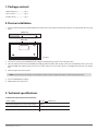
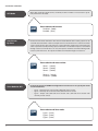
1. Detach Keyboard holder from EKB3 keyboard and fix it to the wall. Keyboard holder detach points are marked with rows (see Fig.
No. 1).
DOWN SIDE
BACK SIDE
Fig. No. 1
2. Disconnect security system ESIM264 power supply and backup battery before connecting the wires.
3. Connect keyboard connectors to ESIM264. Accordingly, AUX+ to AUX+, AUX- to AUX-, Y to Y, G to G. Keyboard Z1 zone connect to
keyboard COM with 5,6kΩ resistor. Zone Z2 is not active and there is no need to connect it. Configure DIP switches (see chapter
3.4).
4. Infix the keyboard into the holder.
NOTE: Pay attention to the tamper when fixing the keyboard to the keyboard holder. It must be properly pressed.
5. Turn on ESIM264 power supply.
4. EKB3 keyboard is ready to use.
3. Technical specifications
3.1 Electrical and mechanical characteristics
Power supply
12-14V
Maximum keyboard connection cable length
100 m.
Dimensions
140x100x18mm
Range of Operating Temperatures
0...+55ºC
USER MANUAL EKB3 V1.0
150mA max
3
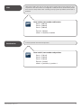
3.2 LED indicator functionality
ARMED
Armed security status indicator
READY
Indicates when all zones are inactive
SYSTEM
Administrator mode activation indicator
ACK SIDE
BYPS
Temporary zone disconnection status indicator
1-12
Indicates violated zones
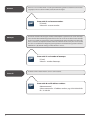
3.3 Connector functionality
AUX+
Positive supply pin 12-14V
AUX-
Negative supply pin 12-14V
connected to the main unit AUX+
G
G pin connected to the main unit G
Y
Y pin connected to the main unit Y
COM
Common contact
Z1
Security zone
Z2
Inactive zone
connected to the main unit AUX-
BACK SIDE
FRONT SIDE
A
B
ARMED
READY
SYSTEM
1
BYPS
7
2
8
3
4
5
6
9
10
11
12
1
2
3
STAY
4
5
6
BYPS
7
8
9
INST
*
0
#
CODE
TAMPER
ON
OFF
DIP SWITCH
Fig. No. 2
COM Y AUXZ2
Z1
G AUX+
Fig. No. 3
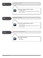
TAMPER
3.4 DIP switches
ON
OFF
Fig. No. 4
DIP SWITCH
COM Y AUXZ2
Z1
G AUX+
DIP switches are used to set keyboard address. ESIM264 allows to connect up to 4 EKB3 keyboards.
Every keyboard must have different address (two keyboards cannot be configured with the same
DIP switch combination). Possible configuration combinations are displayed in the table below.
NOTE: Third switch is not active and its position is irrelevant.
4
1
2
Address
OFF
OFF
Keyboard 1
ON
OFF
Keyboard 2
OFF
ON
Keyboard 3
ON
ON
Keyboard 4
4. Operation description
When the system is disarmed and operating normally it will display green LED called READY. When any zone is violated, the green
LED called READY turns off and the red LED with the number of violated zone shows up. System sound signaler uses two type of
signals - three short beeps and one long beep. Three short beeps stands for successful complete tasks and one long beep stands for
unsuccessful complete tasks. Star (*) button stands for cancel.
4.1 Arming-Disarming the system
To arm the security system user have to enter a valid keyboard password. The system starts to count the time dedicated to leave the
premises. The user is informed about the time countdown by a sound signal. When system is successful armed, the red LED called
ARMED displays.
To disarm the security system user have to enter a valid keyboard password. When users enters into secured premises, the system
starts to count the time dedicated to enter keyboard password. If users will no enter a valid keyboard password – the system will cause
an alarm. When system is successful disarmed, the red LED called ARMED turns off.
4.2 System troubles
Yellow LED called SYSTEM indicates system troubles. To check the specific trouble use command [CODE#], where CODE means a
button named CODE. The system for 15 seconds shows troubles with zones red LED indicators. The specific troubles are displayed in
the table below.
Zone number
Trouble
1
Tamper
2
Backup battery
3
Main power
4
Time
5
High zones*
6
GSM connection
* High zones are troubled zones above 12.
If yellow LED called SYSTEM is blinking means that there are violated zones or tampers above 12. To check which zone is violated use
command [CODE1], where CODE means a button named CODE. To check which tamper is violated use command [CODE2], where
CODE means a button named CODE. The keyboard will display a code of violated zone. To know which zone or tamper above 12 is
violated, use a formula B+A, e.g. if system displays zones 5 and 10, means that violated zone is 30+5=35.
A
B
Zone number 1 = 1
Zone number 7 = 12
Zone number 2 = 2
Zone number 8 = 18
Zone number 3 = 3
Zone number 9 = 24
Zone number 4 = 4
Zone number 10 = 30
Zone number 5 = 5
Zone number 11 = 36
Zone number 6 = 6
Zone number 12 = 42
4.3 Bypassing zones
To bypass any zone use the command [BYPSxxyyyy#], where BYPS - means a button named BYPS, xx – zone number and yyyy – keyboard password. Use the same command to enable bypassed zones. The zone can be bypassed only for temporary period and after
arming-disarming the system it will be active again.
4.3 Configuration commands
To use configuration commands user have to enter administrator code. Administrator code can be entered to the system with command [*XXXX#], where XXXX – administrator code. When administrator code is entered successfully the red LED called ARMED starts
blinking.
USER MANUAL EKB3 V1.0
5
4.3.1 Users commands
Allow Only
Preset Users
When this function is enabled, the system reacts to the SMS messages-commands that are
sent only from registered telephone numbers. If this function is disabled, the device can be
controlled by all users who know the number of the SIM card inserted in the device, control
commands and the main password. Factory default setting – enabled.
EKB3
SMS All
Enter code 21 and function:
Disabled – [210#]
Enabled - [211#]
When this function is enabled, the system sends information messages to the main user
(User1) about armed/disarmed security system. By default this function is disabled.
EKB3
6
Enabled – [120#]
Disabled - [121#]
When this function is enabled, in the case of an alarm, the system simultaneously sends
SMS messages to all entered users. By default this function is disabled. When this function
is disabled, SMS messages are delivered in a sequence starting with the first user (User1).
The message will be sent to the next user only in the case the device does not receive a
confirmation about a successful SMS message delivery to the first recipient.
EKB3
Inform about
Arming/Disarming
Enter code 12 and function:
Enter code 22 and function:
Disabled – [220#]
Enabled - [221#]
Disable Call
during Alarm
A function disabling calls to the specified users in the case of an alarm. By default, this
function is disabled.
EKB3
Disable SMS
during Alarm
Enter code 31 and function:
Disabled – [310#]
Enabled - [311#]
Indicates partition in which user is assigned.
EKB3
USER MANUAL EKB3 V1.0
Disabled – [300#]
Enabled - [301#]
A function disabling SMS message delivery to the specified users in the case of alarm. By
default, this function is disabled.
EKB3
User Partition
Enter code 30 and function:
Enter code 59, user number and partition:
User 1 – [5901x#]
User 2 – [5902x#]
User 3 – [5903x#]
User 4 – [5904x#]
User 5 – [5905x#]
where x – 0: partition 0, 1: partition 1.
7
iButton Partition
Indicates partition in which iButton key is assigned.
EKB3
Enter code 60, iButton number and partition:
iButton 1 – [6001x#]
iButton 2 – [6002x#]
iButton 3 – [6003x#]
iButton 4 – [6004x#]
iButton 5 – [6005x#]
where x – 0: partition 0, 1: partition 1.
4.3.2 Password commands
SMS Password
The main 4 digit SMS password which is used for system configurations and control via SMS
messages. By default, password is 0000, which is NECESSARY to change.
EKB3
Keyboard Password
[14xxxx#]
where xxxx – 4 digit SMS password.
The 4 digits keyboard password which is used to arm/disarm the system security with a
keyboard. By default, this password is 1111, which is recommended to change. Users can
enter up to 10 different keyboard password.
EKB3
8
Enter code 14 and new SMS password:
Enter code 15, keyboard code number and new keyboard code:
[15xxyyyy#]
where xx – keyboard code number, yyyy – 4 digits new keyboard code.
Change Keyboard
Password
This function changes entered keyboard password with new one.
EKB3
Enter code 63, old keyboard password and
new keyboard password:
[63xxxxyyyy#]
where xxxx – old keyboard password, yyyy - new keyboard password.
Add Keyboard
Password
This function adds new keyboard password.
EKB3
Delete Keyboard
Password
Enter code 65 and keyboard password:
[65xxxx#]
where xxxx – keyboard password.
The 4 digits administrator password which is used to configure system settings with a keyboard. By default, this password is 1470, which is recommended to change.
EKB3
USER MANUAL EKB3 V1.0
[64xxxx#]
where xxxx – new keyboard password.
This function deletes keyboard password.
EKB3
Admin Password
Enter code 64 and new keyboard password:
Enter code 16 and new administrator password:
[16xxxx#]
where xxxx – 4 digits new administrator password.
9
4.3.3 Zones commands
ATZ Mode
When ATZ mode (zone duplication) is enabled, the zone number is increased to 12. By default, ATZ mode is disabled.
EKB3
Arm-Disarm
By Zone
Disabled – [280#]
Enabled - [281#]
Choose the zone which will work in Arm-Disarm mode. With this zone security system can be
activated/deactivated with a “low” level impulse which is not shorter than 3 seconds. This mode
can be set only for one zone. No resistance is connected when using 6 zone connection type
and the input must be NO (normally open). If ATZ mode is enabled the impulse is transmitted
through resistance. If Z2-Z6 zones are used, the impulse should be transmitted through 5.6k
resistance, if Z7-Z12 zones - the impulse should be transmitted through 3.3k resistance.
EKB3
Zone Mode No ATZ
Enter code 28 and function:
Enter code 34 and zone number:
Zone 1 – [3401#]
Zone 2 – [3402#]
Zone 3 – [3403#]
…
Zone 12 - [3412#]
Disabled – [3400#]
In the environment of ESIM264 Configuration Tool the user must specify the mode
of connected Zones:
• Type1 – Normally open contact with 5,6KΩ end of line resistor.
• Type2 – Normally closed contact with 5,6KΩ end of line resistor.
• Type3 – Tamper and 5,6KΩ end of line resistor and 3,3KΩ end of line resistor with
normally closed contact.
EKB3
10
Enter code 38 and Zone mode:
Type1 – [381#]
Type2 – [382#]
Type3 – [383#]
Zone Mode ATZ
In the environment of ESIM264 Configuration Tool the user must specify the mode
of connected Zones:
• Type4 – 5,6KΩ end of line resistor and normally closed contact with 3,3KΩ end of line
resistor and normally closed contact. This type of connection is used for ATZ mode.
• Type5 – Tamper and 5,6KΩ end of line resistor and 5,6KΩ end of line resistor with
normally closed contact and 3,3KΩ end of line resistor with normally closed contact.
This type of connection is used for ATZ mode.
EKB3
Zone Status
Type4 - [391#]
Type5 - [392#]
Zone Status parameter is used to enable/disable zones.
EKB3
USER MANUAL EKB3 V1.0
Enter code 39 and Zone mode:
Enter code 52, zone number and function:
Zone 1 – [5201x#]
Zone 2 – [5202x#]
Zone 3 – [5203x#]
...
Zone 44 – [5244x#]
where x – 0: disabled, 1: enabled.
11
Zone Type
Follow – this zone doesn't react to violations during Delay time.
Instant - when this zone is violated, immediately cause an alarm.
Delay - doesn't react to violations in time period which is used to enter security password.
24H - this zone is active all the time, even when the system is disarmed.
Fire - this type of zone is used to connect smoke detectors.
Silent - this zone works as 24H zone and when it is violated, the system doesn't turn on
the siren.
EKB3
Entry Delay
Follow - [53xx1#]
Instant - [53xx2#]
24H - [53xx3#]
Delay - [53xx4#]
Fire - [53xx5#]
Silent - [53xx6#]
where x – zone number. Parameter range from 01 to 44
This field is used to configure the time which is dedicated to disarm the security system
when users enters in the specified Delay zone. If system will not be disarmed in time, the it
will cause an alarm. By default, this time is 15 seconds. This parameter can be adjusted on
for Delay type zones.
EKB3
12
Enter code 52, zone number and function:
Enter code 54, zone number and function:
Zone 1 – [5401x#]
Zone 2 – [5402x#]
Zone 3 – [5403x#]
...
Zone 44 – [5444x#]
where x – time in seconds.
STAY
STAY mode enables the users to arm and disarm security while staying inside the secured premises. The zones which are configured as STAY, will not be secured if the person
does not leave the premises after activating security system. By default, this function is
disabled.
EKB3
Zone Partition
Zone 1 – [5601x#]
Zone 2 – [5602x#]
Zone 3 – [5603x#]
...
Zone 44 – [5644x#]
where x – 0: disabled, 1: enabled.
Indicates partition in which zone operates.
EKB3
USER MANUAL EKB3 V1.0
Enter code 56, zone number and function:
Enter code 57, zone number and partition:
Zone 1 – [5701x#]
Zone 2 – [5702x#]
Zone 3 – [5703x#]
...
Zone 44 – [5744x#]
where x – 0: partition 0, 1: partition 1.
13
4.3.4 Monitoring station commands
CID Enable
When this function is enabled, the system generates CONTACT ID messages and delivers
them to monitoring stations. When this function is disabled, the system operates in normal
mode, i. e., delivers messages only to registered users (other configurations in MS Settings
section becomes inactive).
EKB3
CID Messages
Enter code 23 and function:
Disabled – [230#]
Enabled - [231#]
Configure which Contact ID messages will be delivered to monitoring station. By default,
all these messages are activated.
Alarm/Restore Event – the messages about system alarm and restore events.
External Power Loss/Restore Event – the messages about external power supply loss and
restore events.
Akum Status Event – the messages about backup battery flat status.
Armed Event - the messages about security system arming events.
Disarmed Event - the messages about security system disarming events.
Test Event - the messages with test information about the status of the device.
EKB3
14
Enter code 24, event number and function:
Alarm/Restore Event - [2401x#]
External Power Loss/Restore Event - [2402x#]
Akum Status Event - [2403x#]
Armed Event - [2404x#]
Disarmed Event - [2405x#]
Test Event - [2406x#]
where x – 0: disabled, 1: enabled.
User Messages
When CID Enabled
Configure which events SMS messages will be delivered to users when monitoring station
function is enabled. By default, all these messages are inactive.
Alarm Event – the messages about alarm events.
Disarmed Event – the messages about disarm events.
Armed Event – the messages about arm events.
External Power Loss Event – the messages about external power supply loss events.
External Power Restore Event – the messages about external power supply restore
events.
Akum Status Event – the messages about backup battery flat status.
Test Event - the messages with test information about the status of the device.
EKB3
Monitoring Station
Phone Numbers
Enter code 25, event number and function:
Alarm Event - [2501x#]
Disarmed Event - [2502x#]
Armed Event - [2503x#]
External Power Loss Event - [2504x#]
External Power Restore Event - [2505x#]
Akum Status Event - [2506x#]
Test Event - [2507x#]
where x – 0: disabled, 1: enabled.
Configure monitoring station phone numbers. The first phone number is the main monitoring station number and the other two are alternative. Phone numbers can contain from
7 to 15 numbers.
EKB3
Enter code 26, phone number (01-03) and monitoring station
phone number:
[26xxyyyyyyyyyyy #]
where xx – phone number, yyyyyyyyyyy – monitoring station phone number.
USER MANUAL EKB3 V1.0
15
Account
A device access number which is used by the Monitoring station to determine the monitoring object. Initial account number (9999) must be changed.
EKB3
Attempts
Enter code 37 and number of attempts:
[37xx#]
where xx – number of attempts.
IP address of the router that the server is connected to.
EKB3
16
[27xxxx#]
where xxxx – account number.
This field is used for indicating the number of attempts the system tries to call on the telephone number of the Monitoring Station if the initial call was unsuccessful. If all the attempts
were unsuccessful the system goes to the next Monitoring Station number in the hierarchy.
If the call to the last telephone number Alternate Num2 in the hierarchy was unsuccessful,
the calls are made from the beginning starting with the main Monitoring Station number (
TelNumber1 ). By default settings, number of these calls is 5.
EKB3
Server IP
Enter code 27 and account number:
Enter code 40 and IP address numbers:
{40xxxxxxxxxxxx]
where xxxxxxxxxxxx – IP address numbers, e.g. 001010100254 for
IP: 1.10.100.254
DNS1
Primary DNS server IP address.
EKB3
DNS2
Enter code 42 and DNS2 IP address numbers:
{42xxxxxxxxxxxx#]
where xxxxxxxxxxxx – DNS2 IP address numbers, e.g. 001010100254
for IP: 1.10.100.254
System can work via TCP or UDP protocol.
EKB3
USER MANUAL EKB3 V1.0
{41xxxxxxxxxxxx#]
where xxxxxxxxxxxx – DNS1 IP address numbers, e.g. 001010100254
for IP: 1.10.100.254
Primary DNS server IP address.
EKB3
Protocol
Enter code 41 and DNS1 IP address numbers:
Enter code 43 and function:
TCP - [430#]
UDP – [431#]
17
Server Port
Router port number used for communicating with the device.
EKB3
Local Port
[45x]
where x – port number.
Enter code 46 and test period:
[46x#]
where x – test period.
Identification number of device, which receives CONTACT ID protocol messages via GPRS. This
parameter is only useful when security system works with EGR100 software.
EKB3
18
Enter code 45 and port number:
Period time of sending CONTACT ID protocol messages to monitoring station. The recommended value using GPRS Network is 60 and for GSM connection – 0.
EKB3
Device ID
[44x#]
where x – port number. Parameter range from 0 to 65535.
Local port number used for communicating with the device. Parameter range from 0 to 65535.
EKB3
Test Period
Enter code 44 and port number:
Enter code 47 and device ID:
[47x#]]
where x – device ID.
Communication
Type
Communication type which is used to transfer CONTACT ID protocol and can be set to operate
via voice calls (GSM audio channel) or GPRS network.
EKB3
Enter code 48 and select communication type:
GPRS Network – [480#]
Voice Calls - [481#]
4.3.5 Temperature commands
ATTENTION: If you don‘t want to receive messages about temperature changes - temperature Min and Max parameters must be
set zeros. However, if the sensor is connected, temperature information will be sent together with INFO message.
Min
Temperature sensors minimal marginal temperature. The temperature is measured in degrees
Celsius. Type zeros if the temperature sensor is not used or if you don't want to let the system
to react to the temperature indication.
EKB3
Max
[19xx#]
where xx – number of degrees in Celcius.
Temperature sensors maximum marginal temperature. The temperature is measured in degrees Celsius. Type zeros if the temperature sensor is not used or if you don't want to let the
system to react to the temperature indication.
EKB3
USER MANUAL EKB3 V1.0
Enter code 19 and degrees in Celsius:
Enter code 20 and degrees in Celsius:
[20xx#]
where xx – number of degrees in Celcius.
19
Temperature
Limit Info SMS
When this function is enabled, system sends the information by SMS messages about temperature deviation from the set values. By default, this function is enabled.
EKB3
Enter code 50 and function:
Disabled – [500#]
Enabled - [501#]
4.3.6 Other commands
Alarm time
This parameter is used for setting the time of device alarm siren sound after the alarm is activated. The time is indicated in minutes. Factory default setting – 1 minute. Parameter range
from 00 to 10.
EKB3
Info SMS scheduler
[10xx#]
where xx – minutes.
The system ESIM264 periodically sends information messages about device status. The user
can specify the frequency and time of these continuous messages. Time – specifies the time
at which information message will be delivered. Parameter range from 01 to 23. Period – specifies after how many days repetitive information messages are delivered. Parameter range
from 01 to 255.
EKB3
20
Enter code 10 and count of minutes:
Enter code 11, time and period:
[11xxyy#]
where xx – time, yy – period .
Check External
Power Status
When this function is enabled the system informs users by SMS message about external power cut-off and restore. Factory default setting – enabled.
EKB3
Users
Enter code 17, user number and phone number:
[17xxyyyyyyyyyyy#]
where xx – user number, yyyyyyyyyyy – user phone number.
Enable this function if you want to register iButton keys to the system. After registering iButton
keys, this function must be disabled.
EKB3
USER MANUAL EKB3 V1.0
Disabled – [130#]
Enabled - [131#]
Users are authorized phone numbers for which the system ESIM264 will allow performing
configurations. It is necessary to enter only phone number of the first user and it is possible to
enter up to 5 numbers. User must type mobile number in the international format (it consist of
only those digits that overseas callers must type: 44[area code][local number]) without symbol
'+'. Users phone numbers can contain from 7 to 15 numbers.
EKB3
New iButton keys
Write Enable
Enter code 13 and function:
Enter code 18 and function:
Enabled – [180#]
Disabled - [181#]
21
Bell Squawk Enable
A short siren informs about enabled/disabled security system.
EKB3
Chime Enable
Enter code 32 and function:
Disabled – [320#]
Enabled - [321#]
Enable this function when module EPGM8 is used. The number of outputs will be increased
to 12 units.
EKB3
22
Disabled – [290#]
Enabled - [291#]
When this function is enabled, users will be informed with sound signal of the keyboard speaker about any triggered Delay zone sensors even when the system security is not activated.
By default, this function is enabled.
EKB3
Using Module
EPGM8
Enter code 29 and function:
Enter code 33 and function:
Disabled – [3302#]
Enabled - [3312#]
Language
ESIM264 communicates with on of these languages: Lithuanian, Russian, English, Estonian,
Latvian, German or Slovakian.
EKB3
Log Enable
Enter code 36 and function:
Disabled – [360#]
Enabled - [361#]
This function enables and disables automatic output control. Specific automatic output
control configuration can be done only with software “ELDES Configuration Tool”.
EKB3
USER MANUAL EKB3 V1.0
Lithuanian language - [3500#]
Russian language - [3501#]
English language - [3502#]
Estonian language - [3503#]
Latvian language - [3504#]
German language - [3505#]
Slovakian language - [3506#]
When this function is enabled, the system logs all information about system configuration,
system actions and info messages to the events log. By default, this function is disabled.
EKB3
Control Status
Enter code 35 and function:
Enter code 49 and number of attempts:
1 – [4901x#]
2 – [4902x#]
3 – [4903x#]
…
10 - [4916x#]
where x – 0: disabled, 1: enabled.
23
Keyboard Partition
Indicates partition in which operates the keyboard.
EKB3
Reset To Default
Enter code 62 and administrator password:
[62xxxx#]
where xxxx – administrator password.
This function enables to change date and time settings.
EKB3
24
Keyboard 1 – [5101x#]
Keyboard 2 – [5102x#]
Keyboard 3 – [5103x#]
Keyboard 4 – [5104x#]
where x – 0: partition 0, 1: partition 1.
This function resets all device parameters to default values.
EKB3
Time Settings
Enter code 51 and function:
Enter code 66, date and time:
[66yyyymmddhhxx#]
where yyyy – years, mm – months, dd - days, hh - hours, xx – minutes.
5. Additional Information
Limited Liability
The buyer must agree that the system will reduce the risk of fire, theft, burglary or other dangers but does not guarantee against such
events. “ELDES UAB” will not take any responsibility regarding personal or property or revenue loss while using the system. “ELDES
UAB” liability according to local laws does not exceed value of the purchased system. “ELDES UAB” is not affiliated with any of the
cellular providers therefore is not responsible for the quality of cellular service.
Manufacturer Warranty
The system carries a 24-month warranty by the manufacturer “ELDES UAB”. Warranty period starts from the day the system has been
purchased by the end user. The warranty is valid only if the system has been used as intended, following all guidelines listed in the
manual and within specified operating conditions. Receipt must be kept as a proof of purchase date. The warranty is voided if the
system has been exposed to mechanical impact, chemicals, high humidity, fluids, corrosive and hazardous environment or other
force majeure factors.
Safety instructions
Please read and follow these safety guidelines in order to maintain safety of operators and people around:
• Don’t use the system where it can be interfere with other devices and cause any potential danger.
• Don’t use the system with medical devices.
• Don’t use the system in hazardous environment.
• Don’t expose the system to high humidity, chemical environment or mechanical impacts.
• Don’t attempt to personally repair the system. Any system repairs must be done only by qualified, safety aware personnel.
Keyboard EKB3 is a device mounted in limited access areas. Any system repairs must be done only by qualified, safety aware
personnel.
The system must be powered by 12-14V
easily accessible.
150mA power supply and must be approved by LST EN 60950-1 standard and be
Mains power must be disconnected before any installation or tuning work starts. The system installation or maintenance must
not be done during stormy conditions.
The WEEE (Waste Electrical and Electronic Equipment) marking on this product (see right) or its documentation indicates that the product must not be disposed of together with household waste. To prevent possible harm to human
health and/or the environment, the product must be disposed on in an approved and environmentally safe recycling
process. For further information on how to dispose of this product correctly, contact the system supplier, or the local
authority responsible for waste disposal in your area.
Copyright © “ELDES UAB”, 2010. All rights reserved
It is not allowed to copy and distribute information in this document or pass to a third party without advanced written
authorization by “ELDES UAB”. “ELSDES UAB” reserves the right to update or modify this document and/or related products
without a warning. Hereby, “ELDES UAB” declares that this EKB3 keyboard is in compliance with the essential requirements
and other relevant provisions of Directive 1999/5/EC. The declaration of conformity may be consulted at www.eldes.lt/ce
USER MANUAL EKB3 V1.0
25
Made in Lithuania. Pagaminta Lietuvoje.
www.eldes.lt