1
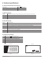
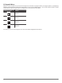
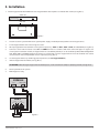
Тел: +7 495 7907870 Моб: +7 965 4429948 Skype: Discoverytelecom Mail: [email protected] www.discoverytelecom.ru LED KEYPAD EKB3 User Manual v1.4 Compatible with: • ESIM264 v07.14.02 and up. • ESIM364 v02.06.01 and up. Main features: • • • • • • • Alarm system arming & disarming; Stay mode activation & deactivation; System parameter configuration; PGM output control; Visual indication by LED indicators; Audio indication by built-in buzzer; Keypad partition switch. EKB3 is a LED keypad intended to use with ELDES alarm systems. The system configuration by EKB3 keypad is performed by activating the Configuration Mode and entering the required parameters & values. ELDES alarm systems allow to connect up to 4 EKB3 keypads. 1. Package content 1. EKB3............................................. qty. 1 2. User manual............................. qty. 1 3. 5,6kΩ resistor........................... qty. 1 2 2. Technical specifications 2.1 Electrical and mechanical characteristics Power supply 12-14V Maximum keypad connection cable length 100 m. 150mA max Dimensions 140x100x18mm Range of Operating Temperatures -30...+55ºC 2.2 LED Functionality ARMED Steady ON - alarm system is armed / exit delay in progress; flashing - Configuration mode activated READY Steady ON - system is ready – no violated zones and tampers SYSTEM Steady ON - system faults; flashing - violated high-numbered zones BYPS Steady ON - zone bypass mode 1-12 Steady ON - violated zone 2.3 Keys Functionality [BYPS] Zone bypass mode [CODE] System fault list / violated high-numbered zone indication / violated tamper indication [*] 1st character for Configuration mode activation/deactivation command (for ESIM364 up to v02.06.20 and ESIM264 all versions) / clear typed in characters / keypad partition switch (if enabled; only for ESIM264) [#] Confirm (enter) command [0] ... [9] Command typing [1] ... [4] Keypad partition switch (only for ESIM364) / steady ON - armed partition indication (only for ESIM364) / flashing - violated partition indication (only for ESIM364) [0] Simultaneous 4-partition arming (only for ESIM364) [STAY] Manual system arming in Stay mode [INST] 1st character for Configuration mode activation/deactivation command (only for ESIM364 v02.07.00 and up) 2.4 Connector functionality AUX+ Positive 12-14V AUX- Negative 12-14V power supply terminal G RS485 interface for communication (green wire) Y RS485 interface for communication (yellow wire) COM Common terminal for Z1 Z1 Security zone terminal Z2 N/A power supply terminal BACK SIDE FRONT SIDE A B ARMED READY SYSTEM 1 BYPS 7 8 2 9 3 4 5 6 10 11 12 1 2 3 STAY 4 5 6 BYPS 7 8 9 INST * 0 # CODE Fig. No. 1 USER MANUAL EKB3 V1.4 3 2 TAMPER COM Y AUXZ2 Z1 G AUX+ DIP SWITCH Fig. No. 2 3 2.5 Keypad Address Jumpers 2 and 3 located on the back side of the keypad are intended to set keypad address. The keypad address is configured by setting the jumper positions. ELDES alarm system allows to connect up to 4 EKB3 keypads - each set under different address. Jumper combinations for different keypad address configuration are indicated in the table below. Contacts Position Address 3 2 Keypad 1 3 2 Keypad 2 3 2 Keypad 3 3 2 Keypad 4 The address of each connected keypad is also indicated in ELDES Configuration Tool software. 4 3. Installation 1. Detach keypad holder from EKB3 front side . Keypad holder detach points are marked with arrows (see Fig. No. 3). DOWN SIDE BACK SIDE Fig. No. 3 2. Disconnect alarm system ELDES alarm system power supply and backup battery before connecting the wires. 3. Fix the keypad holder on the wall using the screws. 4. Wire up keypad terminals to ELDES alarm system respectively – AUX+ to AUX+, AUX- to AUX-, Y to Y, G to G (see Fig. No. 4). 5. Connect a sensor and the resistor across Z1 and COM terminals in accordance with zone connection Type 1 or Type 2 (see alarm system installation manual). As keypad zone Z1 is disabled by default, it can be enabled by SMS, ELDES Configuration Tool, EKB2, EKB3 and EKB3W keypad. Z2 terminal is permanently inactive. Keypad zone Z1 must be enabled and resistor connected even if the tamper button alone is required (see Fig. No. 4). 6. Set the keypad address by combining jumper positions (see 2.5 Keypad Address). 7. Infix the keypad into the holder (see Fig. No. 3). ATTENTION! Before fixing the keypad into the holder please , make sure that the tamper is properly pressed (see Fig. No. 2). 8. Power up ELDES alarm system. 9. EKB3 keypad is ready. ESIM364 Y G AUX- AUX+ EKB3 COM Y AUXZ2 Z1 G AUX+ 5,6kΩ USER MANUAL EKB3 V1.4 Fig. No. 4 5 4. EKB3 Zone and Tamper Keypad EKB3 has one wired zone Z1 and one tamper button. By default, the keypad zone Z1 is disabled. The keypad zone can be enabled by SMS, keypad and ELDES Configuration Tool. When Z1 is enabled, it operates like any other system zone, therefore a sensor can be connected to it. In addition, Z1 and COM terminals must be connected with resistor of 5,6kΩ nominal. The tamper button is intended for monitoring the enclosure status of EKB3, therefore the system causes alarm if the enclosure is illegally opened. Keypad zone Z1 must be enabled and resistor connected even if the tamper button alone is required. 5. Partition Control and Indications ATTENTION: The features described below are only available with the system ESIM364 and requires keypad partition switch feature. EKB3 keypad can operate in the following modes: • 2-partition mode – This parameter determines whether EKB3 keypad can operate only in one of the first two system partitions allowing to arm/disarm them and switch the keypad partition using [1]... [2] keys. This mode is set up by default. • 4-partition mode – This parameter determines whether EKB3 keypad can operate in one of the four system partitions allowing to arm/disarm them, indicate arm/disarm status, zone state on [1]... [4] keys and switch the keypad partition using [1]... [4] keys. To switch the keypad partition using EKB3 keypad, please press and hold [1]... [2] key (2-partition mode) / [1]... [4] key (4-partition mode) for 2 seconds to apply the command. Upon successful keypad partition change, the keypad buzzer will emit three short beeps. In case of an alarm: • 2-partition mode - Red zone indicator (-s) will light ON indicating the corresponding the violated zone number (Z1-Z12) or SYS TEM indicator will flash or light ON indicating the violated high-numbered zone (Z13 and up) or tamper respectively. • 4-partition mode - [1]... [4] key will flash in orange, corresponding the partition that contains violated zones/tampers. Arming/disarming To arm the partition that the keypad is switched to, please enter a valid user code, assigned to the respective partition. • 2-partition mode - The armed partition number will be indicated by illuminated indicator ARMED on indicators‘ section A or B corresponding partition 1 or 2 respectively. • 4-partition mode - The armed partition number will be indicated by illuminated [1]... [4] key in orange. To arm all 4 partitions simultaneously, please follow these steps: 1. Press and hold [0] key. 2. Keep holding the key until you hear three short beeps. 3. Release the key and enter a valid user password, assigned to all 4 partitions. Upon the successful arming process, [1], [2], [3], [4] keys will light ON in orange. NOTE: Arming/disarming all partitions simultaneously is NOT supported by 2-partition mode. 6 6. Additional Information Limited Liability The buyer must agree that the system will reduce the risk of fire, theft, burglary or other dangers but does not guarantee against such events. “ELDES UAB” will not take any responsibility regarding personal or property or revenue loss while using the system. “ELDES UAB” liability according to local laws does not exceed value of the purchased system. “ELDES UAB” is not affiliated with any of the cellular providers therefore is not responsible for the quality of cellular service. Manufacturer Warranty The system carries a 24-month warranty by the manufacturer “ELDES UAB”. Warranty period starts from the day the system has been purchased by the end user. The warranty is valid only if the system has been used as intended, following all guidelines listed in the manual and within specified operating conditions. Receipt must be kept as a proof of purchase date. The warranty is voided if the system has been exposed to mechanical impact, chemicals, high humidity, fluids, corrosive and hazardous environment or other force majeure factors. Safety instructions Please read and follow these safety guidelines in order to maintain safety of operators and people around: • DO NOT use the system where it can be interfere with other devices and cause any potential danger. • DO NOT use the system with medical devices. • DO NOT use the system in hazardous environment. • DO NOT expose the system to high humidity, chemical environment or mechanical impacts. • DO NOT attempt to personally repair the system. Keypad EKB3 is a device mounted in limited access areas. Any system repairs must be done only by qualified, safety aware personnel. Keypad EKB3 must be powered by 12-14V 150mA power supply and must be approved by LST EN 60950-1 standard and be easily accessible. Main power must be disconnected before any installation or tuning work starts. The system installation or maintenance must not be done during stormy conditions. The WEEE (Waste Electrical and Electronic Equipment) marking on this product (see left) or its documentation indicates that the product must not be disposed of together with household waste. To prevent possible harm to human health and/or the environment, the product must be disposed on in an approved and environmentally safe recycling process. For further information on how to dispose of this product correctly, contact the system supplier, or the local authority responsible for waste disposal in your area. USER MANUAL EKB3 V1.4 7