1
The
Freedom System
2
for Maxicom
Instruction Manual
Contents
List of figures . . . . . . . . . . . . . . . . . . . . . . . . . . . . . . . . . . . . . . . . . . . . . . . . . . . . . . . . . . . . . . . . .v
Chapter 1: Introduction . . . . . . . . . . . . . . . . . . . . . . . . . . . . . . . . . . . . . . . . . . . . . . . . . . . . . . . . . .1
Welcome to the Freedom System . . . . . . . . . . . . . . . . . . . . . . . . . . . . . . . . . . . . . . . . . . . . . . . . . . . . . . . . . . . . . . . . . . 1
System overview . . . . . . . . . . . . . . . . . . . . . . . . . . . . . . . . . . . . . . . . . . . . . . . . . . . . . . . . . . . . . . . . . . . . . . . . . . . . . . . 1
Chapter 2: Installing the Freedom System . . . . . . . . . . . . . . . . . . . . . . . . . . . . . . . . . . . . . . . . . . .3
Packing list
.................................................................................. 3
Configuration . . . . . . . . . . . . . . . . . . . . . . . . . . . . . . . . . . . . . . . . . . . . . . . . . . . . . . . . . . . . . . . . . . . . . . . . . . . . . . . . . . 4
Additional required equipment . . . . . . . . . . . . . . . . . . . . . . . . . . . . . . . . . . . . . . . . . . . . . . . . . . . . . . . . . . . . . . . . . 5
Installing the base unit . . . . . . . . . . . . . . . . . . . . . . . . . . . . . . . . . . . . . . . . . . . . . . . . . . . . . . . . . . . . . . . . . . . . . . . . . . . .6
Installing the central base antenna and surge arrestor . . . . . . . . . . . . . . . . . . . . . . . . . . . . . . . . . . . . . . . . . . . . . . . . . . 8
Installation of the Freedom System telephone interface . . . . . . . . . . . . . . . . . . . . . . . . . . . . . . . . . . . . . . . . . . . . . . . 10
Chapter 3: Using the Freedom System . . . . . . . . . . . . . . . . . . . . . . . . . . . . . . . . . . . . . . . . . . . . .11
System Setup . . . . . . . . . . . . . . . . . . . . . . . . . . . . . . . . . . . . . . . . . . . . . . . . . . . . . . . . . . . . . . . . . . . . . . . . . . . . . . . . . 11
Setting or changing the Freedom password . . . . . . . . . . . . . . . . . . . . . . . . . . . . . . . . . . . . . . . . . . . . . . . . . . . . . . . 11
Setting the Freedom Time Window . . . . . . . . . . . . . . . . . . . . . . . . . . . . . . . . . . . . . . . . . . . . . . . . . . . . . . . . . . . . . 11
System operation . . . . . . . . . . . . . . . . . . . . . . . . . . . . . . . . . . . . . . . . . . . . . . . . . . . . . . . . . . . . . . . . . . . . . . . . . . . . . 14
Understanding the handheld radio . . . . . . . . . . . . . . . . . . . . . . . . . . . . . . . . . . . . . . . . . . . . . . . . . . . . . . . . . . . . . . 14
Sending commands . . . . . . . . . . . . . . . . . . . . . . . . . . . . . . . . . . . . . . . . . . . . . . . . . . . . . . . . . . . . . . . . . . . . . . . . 15
Freedom System responses . . . . . . . . . . . . . . . . . . . . . . . . . . . . . . . . . . . . . . . . . . . . . . . . . . . . . . . . . . . . . . . . . . . 15
2
Interaction between a Freedom user and a local user at Maxicom
. . . . . . . . . . . . . . . . . . . . . . . . . . . . . . . . . . . . . . .15
System Commands . . . . . . . . . . . . . . . . . . . . . . . . . . . . . . . . . . . . . . . . . . . . . . . . . . . . . . . . . . . . . . . . . . . . . . . . . . . . . 16
2
Operating Maxicom from the radio or remote telephone . . . . . . . . . . . . . . . . . . . . . . . . . . . . . . . . . . . . . . . . . 16
Command format examples . . . . . . . . . . . . . . . . . . . . . . . . . . . . . . . . . . . . . . . . . . . . . . . . . . . . . . . . . . . . . 16
Entering access codes . . . . . . . . . . . . . . . . . . . . . . . . . . . . . . . . . . . . . . . . . . . . . . . . . . . . . . . . . . . . . . . . . 16
Contacting the Freedom System by telephone . . . . . . . . . . . . . . . . . . . . . . . . . . . . . . . . . . . . . . . . . . . . . . . . 17
Accessing a typical site with the Freedom System . . . . . . . . . . . . . . . . . . . . . . . . . . . . . . . . . . . . . . . . . . . . . . . 17
Contacting different sites with one phone call . . . . . . . . . . . . . . . . . . . . . . . . . . . . . . . . . . . . . . . . . . . . . . . . . . 18
Summary of Freedom System commands . . . . . . . . . . . . . . . . . . . . . . . . . . . . . . . . . . . . . . . . . . . . . . . . . . . . . . .19
Commands used while on-line with a CCU . . . . . . . . . . . . . . . . . . . . . . . . . . . . . . . . . . . . . . . . . . . . . . . . . . 19
2
Commands used to control Maxicom features . . . . . . . . . . . . . . . . . . . . . . . . . . . . . . . . . . . . . . . . . . . . . . . 23
Chapter 4: Troubleshooting . . . . . . . . . . . . . . . . . . . . . . . . . . . . . . . . . . . . . . . . . . . . . . . . . . . . . .25
Appendix
. . . . . . . . . . . . . . . . . . . . . . . . . . . . . . . . . . . . . . . . . . . . . . . . . . . . . . . . . . . . . . . . . . .29
Telephone interface with the Freedom System . . . . . . . . . . . . . . . . . . . . . . . . . . . . . . . . . . . . . . . . . . . . . . . . . . . . . . . 29
Using the handheld unit for telephone operations . . . . . . . . . . . . . . . . . . . . . . . . . . . . . . . . . . . . . . . . . . . . . . . . . . . . 30
Answering a phone call . . . . . . . . . . . . . . . . . . . . . . . . . . . . . . . . . . . . . . . . . . . . . . . . . . . . . . . . . . . . . . . . . . . . . . 30
Hanging up . . . . . . . . . . . . . . . . . . . . . . . . . . . . . . . . . . . . . . . . . . . . . . . . . . . . . . . . . . . . . . . . . . . . . . . . . . . . . . .30
Making a telephone call . . . . . . . . . . . . . . . . . . . . . . . . . . . . . . . . . . . . . . . . . . . . . . . . . . . . . . . . . . . . . . . . . . . . . 30
Setting up the base unit (6xx* commands) . . . . . . . . . . . . . . . . . . . . . . . . . . . . . . . . . . . . . . . . . . . . . . . . . . . . . . . . . . 31
Caring for the Freedom System equipment . . . . . . . . . . . . . . . . . . . . . . . . . . . . . . . . . . . . . . . . . . . . . . . . . . . . . . . . . 33
iii
Optional equipment . . . . . . . . . . . . . . . . . . . . . . . . . . . . . . . . . . . . . . . . . . . . . . . . . . . . . . . . . . . . . . . . . . . . . . . . . . . 34
Battery life and charging time . . . . . . . . . . . . . . . . . . . . . . . . . . . . . . . . . . . . . . . . . . . . . . . . . . . . . . . . . . . . . . . . . . . 35
FCC regulations . . . . . . . . . . . . . . . . . . . . . . . . . . . . . . . . . . . . . . . . . . . . . . . . . . . . . . . . . . . . . . . . . . . . . . . . . . . . . . . 36
Telephone interface information . . . . . . . . . . . . . . . . . . . . . . . . . . . . . . . . . . . . . . . . . . . . . . . . . . . . . . . . . . . . . . 36
FCC radio regulations . . . . . . . . . . . . . . . . . . . . . . . . . . . . . . . . . . . . . . . . . . . . . . . . . . . . . . . . . . . . . . . . . . . . . . . 37
Service information . . . . . . . . . . . . . . . . . . . . . . . . . . . . . . . . . . . . . . . . . . . . . . . . . . . . . . . . . . . . . . . . . . . . . . . . . . . . 38
iv
List of figures
Figure 1
Configuration of connections between the Freedom System and a serial port . . . . . . . . . . . . . . . . . . . . . . . . . . . . . . . .4
Figure 2
Freedom System base unit . . . . . . . . . . . . . . . . . . . . . . . . . . . . . . . . . . . . . . . . . . . . . . . . . . . . . . . . . . . . . . . . . . . . . . . . .7
Figure 3
Central base antenna (installation detail) . . . . . . . . . . . . . . . . . . . . . . . . . . . . . . . . . . . . . . . . . . . . . . . . . . . . . . . . . . . . .8
Figure 4
Weatherproofing the coaxial cable connections . . . . . . . . . . . . . . . . . . . . . . . . . . . . . . . . . . . . . . . . . . . . . . . . . . . . . . . .9
Figure 5
Ground wire terminal lug and ground wire installation detail of central base antenna . . . . . . . . . . . . . . . . . . . . . . . . .9
Figure 6
Exterior and/or interior mounting of surge arrestor . . . . . . . . . . . . . . . . . . . . . . . . . . . . . . . . . . . . . . . . . . . . . . . . . . . .10
Figure 7
Handheld radio and unit controls . . . . . . . . . . . . . . . . . . . . . . . . . . . . . . . . . . . . . . . . . . . . . . . . . . . . . . . . . . . . . . . . . .14
Figure 8
Configuration of telephone interface with Freedom System . . . . . . . . . . . . . . . . . . . . . . . . . . . . . . . . . . . . . . . . . . . . .29
v
1 Introduction
Welcome to Rain Bird Freedom System
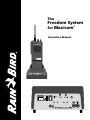
The Maxicom2 Freedom System is a radio-operated system that gives you control of
the Maxicom2 computer and provides voice communication from the field or
remote locations. The system consists of a multi-function telephone and radio
terminal located at the Maxicom2 central location. With the central terminal, you
can use a Freedom handheld radio for two-way radio communication with the
Maxicom2 computer.
System overview
Once you have connected the Freedom System to your Maxicom2 computer, you
can access a site with the handheld radio to perform the following tasks:
Turn on:
• specific station(s) of any satellite for a specific time
• a contiguous block of stations for a specific time
• a schedule
Advance:
• to the next station in the schedule
• a specific step-type schedule
Pause or Resume:
• the entire system
• a specific channel or station
• a specific step-type schedule
Turn off:
• the entire system
• a specific, channel, station, or site
• a specific schedule(s)
1
;@À
2 Installing the Freedom System
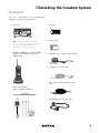
Packing list
Check to be certain that you received the following
equipment in the Freedom System box:
• Base unit
Note: A Freedom handheld radio unit
(voice only) without a keypad is also available.
Contact your local Rain Bird Maxicom
Distributor for ordering information.
• Handheld UHF radio unit with DTMF
keypad, drop-in battery charger and
UHF antenna
• Belt clip
• Battery pack
• 120 VAC power supply (battery charger)
• Computer to repeater cable
• Two 25-feet lengths of RG-8 coaxial
cable
• Base central antenna
and accompanying hardware
• 120 VAC power cord (base unit)
3
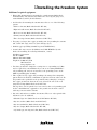
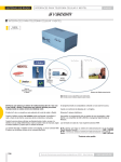
Configuration
You can configure the Freedom System by connecting the base unit to a serial port
on your Maxicom2 computer (see fig. 1). This configuration requires additional
equipment that is not included with the Freedom System. Be certain to obtain the
additional equipment that is required for the installation. (See page 5, “Additional
Equipment.”)
ÀÀ
;;
@@
;
@
À
;
@
À
;;
@@
ÀÀ
À@;
Figure 1: Configuration of connections between the Freedom System and a serial port
4
2 Installing the Freedom System
Additional required equipment
• Heavy-duty antenna mast for mounting the central antenna (Radio Shack
model #15-843). The antenna mast must be five-feet long, 16-gauge steel,
enamel finished, and 1 1/4-inch diameter.
• Steel brackets for mounting the antenna mast. Choose one of the following
options:
–Gable roof mount (Radio Shack model #15-889)
–Eight-inch wall mount (Radio Shack model #15-885)
–Roof eaves mount (Radio Shack model #15-891)
–Chimney mount (Radio Shack model #15-839)
–Three-feet tripod mount (Radio Shack model #15-516)
• Ten-gauge (or larger) bare copper grounding wire for grounding the antenna
and coaxial cable surge arrestor or static discharge device.
• Panduit copper grounding terminal lug (model #CX70-14-C).
• Coaxial cable surge arrestor (PolyPhaser model #IS-IE50LU-C1) with
bracket for mounting. For ordering information, contact:
PolyPhaser Corporation
P.O. Box 9000
Minden, NV 89423-9000
Telephone: 1-800-325-7170
702-782-2511
www.polyphaser.com
• Two brass ground wire clamps for securing wires to a grounding rod. (May
not be required for your installation if you can use an existing MAXI threerod grounding grid, and you can attach it to the grounding screws on the
MGP-1 grounding plate assembly.)
• Three eight-feet long copper clad grounding rods arranged in a triangular
pattern. Each rod should be a minimum of eight feet from any other rod. Tie
the ground rods together below the ground by using a 10-gauge (or larger)
bare copper ground wire between the rods. Connect the wire to the rods
using brass clamps (Radio Shack model #15-529).
The step above is not required if you can connect a three-rod grounding grid
for the central Maxicom2 equipment to the ground wires from the coaxial
cable surge arrestor and the antenna.
• Guy wires and anchors to stabilize the antenna. These are only required if the
antenna needs to be stabilized.
–Galvanized guy wire (Radio Shack model #15-030 or #15-031)
–Guy wire anchors (Radio Shack model #15-825)
–Guy wire turnbuckles (Radio Shack model #15-829)
–Guy wire clamps (Radio Shack model #15-850)
–1 1/4-inch guy wire ring and collar (Radio Shack model #15-835)
5
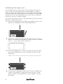
Installing the base unit
Select a suitable location for the base unit, either on a desktop or mounted on a
wall (see below). To avoid possible interference with the Maxicom2 computer
monitor, position the base unit at least six feet away from the monitor, but within
25 feet (the length of the communication cable) of the Maxicom2 computer. Make
sure that you select a location that will allow you to route a 25-feet coaxial cable
from the base unit to the central base antenna.
If you want to mount the base unit on a wall, begin with step 1, below. If you place
the unit on a desktop, skip to step 3.
1. Place the base unit against the wall. With a pencil, mark the position on the
wall where you will drill holes for the four mounting brackets.
2. Drill the holes and mount the base unit on the wall. The specific screws you
will need to mount the base unit will vary according to the type of mounting
surface (i.e., wood, cement, masonry, drywall, etc.).
3. Connect the 120 VAC power cord to the Freedom System base unit. Plug
the cord into a 120 VAC power outlet on the Maxicom2 system’s voltage
stabilizer unit.
Note: Be sure the antenna is connected prior to connecting to the power supply.
4. Connect the the communication cable’s female connector to the Maxicom2
serial port. If your Maxicom2 computer has a 9-pin serial port, you must
purchase a 9-pin to 25-pin adapter from your local computer or electrical
parts supplier.
6
;@À;@À
2 Installing the Freedom System
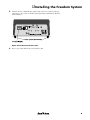
5. Connect the the communication cable’s male connector (a phone jack-type
connector) to the socket on the Freedom System base unit marked “Remote
Control Phone.”
Figure 2: Freedom System base unit
6. Post a copy of the FCC license near the base unit.
7
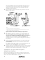
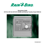
Installing the central base antenna
and surge arrestor
Select a suitable site for installing the antenna that will be both
safe and give it the best performance. Most antennas are
supported by a pipe mast that is attached to the side wall, roof,
chimney, or eaves of a building with brackets, straps, or a tripodtype mount. Antennas can also be attached to self-supporting
towers or masts and may require guying for stability.
Install the antenna directly above your equipment, if possible, so
that the antenna coaxial cable can drop straight down and enter
the building near the equipment (see fig. 6). Generally, the higher
the antenna is above ground, the better it performs. A good practice is to install the antenna about 5 to 10 feet above the roof
line, away from power lines and other obstructions. The FCC
limits your antenna to a maximum height of 20 feet above the
ground.
5
6
3
4
8
Make sure the site has proper clearance of any power lines, trees,
wires, or other obstructions. Measure the overall height of the
antenna:
Height of mast
+ Height of antenna (x 2)
Minimum recommended clearance
height of the mast
+ height of the antenna x 2 = minimum
To install the central base antenna:
7
1. Remove the antenna from the box and assemble it
according the directions included.
2. Connect one 25-feet length of coaxial cable from the
central base antenna to the antenna connection of a coaxial
cable surge arrestor.
Caution: Do not cut the coaxial cable. Lay out the excess cable in as
straight of a line as possible. Do not coil the cable; this will add resistance to data transmission and reception.
9
10
Before placing the antenna whip into the proper whip adapter, be
sure to cut the whip antenna to the proper length which depends on
your licensed frequency. See the chart included with the antenna.
Also be sure to center the U-bolt bracket between two adjacent
ground plane rods (or radials).
11
3. Secure a 1 1/4-inch diameter antenna mast, which should
be at least five-feet long, to the building location you have
selected. Use the proper mounting brackets or other equipment required.
12
2
13
4. Attach one end of one of the RG-8/U coaxial cables to the
“pigtail” coaxial cable at the antenna. Before you mount
the antenna to the antenna mast, refer to fig. 4 for proper
waterproofing of this connection.
14
Figure 3: Central base antenna
(Installation detail)
8
See fig. 6
for an
expanded
view of
installing
the surge
arrestor.
2 Installing the Freedom System
Figure 4: Weatherproofing the coaxial cable connections
5. Attach the antenna to the top of the mast using the U-bolts, nuts, and lock
washers provided with the antenna.
6. Attach a #10 GA (or larger) bare copper grounding terminal lug to one side
of the U-bolt.
Figure 5: Ground wire terminal lug and ground wire installation
detail of central base antenna
7. Route the ground wire along the mast and secure it to both the mast and the
side of the building using proper standoff insulators.
8. Route the coaxial cable along the mast on the opposite side from the ground
wire. Secure the coaxial cable to both the mast and the side of the building
using the proper standoff insulators.
9. Connect the other end of the coaxial cable to the connector marked
“Antenna” on the coaxial surge arrestor.
10. Mount the PolyPhaser coaxial cable surge arrestor to the wall of the building
near the floor. You can mount the surge arrestor on the outside of the wall
(see fig. 6), but make sure to waterproof the coaxial cables connected to it
(see fig. 4).
9
You can also mount the surge arrestor on the inside of the wall (see fig. 6).
Securely attach the surge arrestor by using the surface mounting bracket
attached to it. Place the surge arrestor as close as possible to where the
grounding rod will be grounded.
11. Form a rain drip loop in the coaxial cable at the point before it enters the
building (see figs. 3 and 6).
Notes:
• All exterior connections must be waterproof.
• Keep interior wire run to a minimum with coaxial cable because it is not fire
rated. All interior cable must be fire rated.
Figure 6: Exterior and/or interior mounting of surge arrestor
12. Run a #10 GA (or larger) bare copper wire to the ground terminal of the
surge arrestor, making it as short and as straight as possible. Connect it to
one of the rods of the three-rod grounding grid using a brass ground rod
clamp. If you have the MGP-1 grounding plate assembly, you can connect its
grounding screws to the ground wire on the existing MAXI three-rod
grounding grid. If not, use a brass ground rod clamp and attach it directly to
the ground rod.
13. Connect the ground wire from the antenna to one of the rods of the threerod grounding grid. Attach it directly to the ground rod by using a brass
ground rod clamp.
For a MGP-1 grounding plate assembly, connect its grounding screws to the
ground wire on the existing MAXI three-rod grounding grid.
14. Connect the other end of coaxial cable from the surge arrestor connection marked
“Equipment” and run it to the top (if the base unit is mounted on a wall) or the
back (if the base unit is sitting on a horizontal surface) of the base unit.
Installation of the Freedom System
telephone interface
For the details on installation of a phone line into the Freedom System and the
FCC rules regulations that apply, refer to “Telephone interface with the Freedom
System” on pg. 29, and “FCC regulations” on pg. 36.
10
3 Using the Freedom System
System setup
Setting passwords and changing them periodically protects your system from unauthorized use. You always have complete access to the Maxicom2 system from the
computer keyboard. You only need the password to gain access to the Maxicom2
system when you are using the Freedom handheld radio unit or remote telephone.
You can use one password with the Freedom System. The Freedom password
allows access to all levels of the Freedom System.
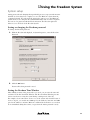
Setting or changing the Freedom password
To change the Freedom password:
1. With the Freedom tab displayed, in System Properties, enter the Freedom
Password.
2. Click the OK button.
Your new Freedom password is saved.
Setting the Freedom Time Window
After defining as many of the passwords as you need, you can enter the start and
end times for the Freedom Time Window. The Freedom Time Window prevents
remote users from accessing the system during certain periods of the day.
For example, if you want remote users to access the system only from the hours of
8 a.m. to 4 p.m., you would enter 8:00 a.m. for the window’s start time and 4:00
p.m. for the window’s end time. Maxicom2 will then block all remote accesses that
are not initialized during those times (except when the master password is used).
11
If you do not enter start and end times, both times will default to 12:00 a.m.,
meaning the window is always open.
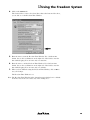
To set the Freedom Time Window:
1. Select Open from the Site menu.
The Open An Existing Site dialog box opens. If you have not set up any sites
yet in Maxicom2, see the Maxicom2 manual for instructions on setting up
sites.
2. Highlight a site for which you would like to set the Freedom Time Window,
and then select Open.
The site opens.
3. Select Properties from the Site menu.
The Site Properties Setup dialog box opens.
12
3 Using the Freedom System
4. Click on the Contact tab.
The Contact Sheet comes to the front. Note that at the bottom of the sheet,
you are able to set the Freedom Time Window.
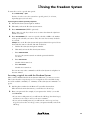
5. Enter the time to start the Freedom Time Window. Use a 12-hour time
format. Or, use the scroll buttons on the right side of the field to enter the
time without typing. You can enter only one start time.
6. Enter the time to end the Freedom Time Window. Use a 12-hour time
format. Or, use the scroll buttons on the right side of the field to enter the
time without typing. You can enter only one end time.
7. When you have finished setting the Freedom Time Window, click on OK to
save your changes.
The Freedom Time Window is set.
Note: The Freedom Time Window in the System Properties dialog box is a default
for all new sites. It does not effect any of the existing sites.
13
System operation
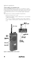
Understanding the handheld radio
The Freedom handheld radio allows you direct access to the Maxicom2 computer
from the field. By entering commands with the radio keypad, you have field control
for individual stations as well as total system control. The radio can also be used to
contact other radios at your site or to receive and make telephone calls from the
field.
While using the radio, you must keep in mind three important rules:
• Monitor the frequency before you talk.
• You must enter a complete command or a ## at least once every four minutes
or Maxicom2 will hang up.
• Once you start a command by entering ##, you must complete it within five
seconds or Maxicom2 will disregard the command and you will hear the error
beep.
Figure 7: Handheld radio and unit controls
14
3 Using the Freedom System
Sending commands
To use the radio to send commands:
1. Turn the volume control knob to the ON position.
The radio runs a quick self-test when you turn it on. If the radio works properly, you will hear a short confirmation tone to indicate the radio is ready for
use. If the radio does not work properly, consult Chapter 4, Troubleshooting
the Freedom System on pg. 25. If you still have difficulty with the radio,
contact your Rain Bird Maxicom distributor.
2. Select the proper channel with the channel select knob. See the handheld
radio manual for information on selecting channels.
3. Press and hold the PTT (push-to-talk) button to enter commands using the
touch-tone keypad or to talk into the microphone.
See “System commands” on pg. 16 for a list of available commands.
As you enter commands with the radio keypad, Maxicom2 will respond with
beeps to indicate whether or not there were any errors. See “Freedom System
responses,” below, for descriptions of the responses.
The length of a telephone call is limited to five minutes. The Freedom System will
emit two short warning beeps 20 seconds before the five minutes expire.
Freedom System responses
As you enter commands into the phone, Maxicom2 will respond with beeps from
the radio to indicate whether or not there were any errors. The following is a list of
the possible Freedom System responses:
• No response. No contact has been made with the Freedom System base unit.
• One short beep. The leading ## had been received (off-line).
• Two short beeps. The leading ## has been received (on-line).
• Four short beeps. OK; the command you entered is being executed and
Maxicom2 is ready to receive another command.
• One long beep. Error; reenter the command.
• Many short beeps. Wait; Maxicom2 is contacting the site you requested or is
hanging up.
• Many long beeps. Busy signal; Maxicom2 is already on-line with a site or a
local user at Maxicom2 terminated your contact.
• Error beep...busy signal. The Freedom Time Window is closed.
• Wait beep...error beep...busy signal. The site you requested did not respond
to the Maxicom2 system call.
Interaction between a Freedom user and a local user
at Maxicom2
The local user at Maxicom2 is always given priority over the Freedom users in the
field. If a local user is manually on-line with a site, the Freedom users are blocked
out (sent a busy signal). If a Freedom user is on-line, the local user may terminate
the Freedom contact at any time.
15
If the local user is manually on-line with a site, and a Freedom user attempts to
initiate contact, a message will appear on the Maxicom2 screen, informing the local
user that Freedom contact is being attempted. The message will ask if the local user
wants to terminate contact. The default answer is “no.”
If the local user wishes to monitor the Freedom user’s activities:
1. Open the site to be monitored.
2. From the Site menu, select Manual Contact, Monitor Site.
3. Open the Communications window. Select the COM port that Freedom is
connected to. You will see both the commands and the actual keys being
entered.
All activities initiated by the Freedom user appear in the log. Maxicom2
dynamically updates the log while the Freedom user is on-line with the site.
The local user can terminate Freedom contact at any time by selecting the
Disconnect command, which displays a warning message. The message indicates
that a Freedom user is on-line and asks if the local user wants to terminate the
Freedom contact. While the local user can then answer “yes” or “no,” the default
answer is “no.” If the local user terminates the Freedom contact, the Freedom user
receives a busy signal.
System commands
Operating Maxicom2 from the radio or remote telephone
To operate Maxicom2 from the handheld radio or a remote telephone, you must
enter commands.
Command format examples
Each command must begin with the ## sign for you to gain access to the system.
This sign is followed by the individual parameters for the group, channel, station,
time, etc., each separated by the # sign. You must enter the ## sign to terminate a
command. The handheld unit will confirm you choices with different beeps. See
“Freedom System responses” on pg. 15 for the meaning of the beeps.
Entering access codes
You can enter the access code from the Freedom radio or by remote telephone. To
enter a password (it must have four digits; in the example below, we use 4321)
from the radio or telephone, use the following example:
To turn on access:
Press ##4321#1##
You have accessed the system. The “1” in the above command opens the
system to access for the default time period, which is eight hours.
To turn off access for an indefinite time period:
Press ##4321#2##
You have closed access to the system. The “2” in the above command closes
access to the system for an indefinite time period.
16
3 Using the Freedom System
To turn off access for a specific time period:
Press ##4321#2#(1 – 9)##
You have closed access to the system for a specific period (1 – 9 hours,
depending upon your selection).
Contacting the Freedom System by telephone
1. Dial the Freedom System telephone number.
2. Wait until you hear the Freedom System answer.
3. Enter ##XXXX#1#tt## (XXXX = password)
Enter a time (tt) only if you desire an access time other than the eight-hour
default access time.
4. Enter ##71#SCHD## (71 = turn on a specific schedule; SCHD = the number
of the specific schedule you want to start). You can enter as many schedules
as you wish.
Example: Access the Freedom System with password 4321 for a period of two
hours and then turn on schedule 112 and schedule 23.
a.
Dial the Freedom System telephone number.
b.
Wait until you hear the Freedom System answer.
c.
Enter ##4321#1#2##
Access to the system is turned on with the password 4321 for
two hours.
d.
Enter ##71#112##
Schedule 112 is turned on.
e.
Enter ##71#23##
Schedule 23 is turned on.
You can enter any other commands to the Freedom System via telephone in
the same manner.
Accessing a typical site with the Freedom System
After you have initialized the Freedom System in Maxicom2, you may access a site.
This section describes a step-by-step access of a typical site. For a detailed description of the available commands, see “Summary of Freedom System commands” on
pg. 19.
1. Dial the phone number for the Maxicom2 system Freedom modem.
When the Freedom modem answers, you will hear one short beep.
2. Enter your password. For example, if your password is “1111,” you would
enter ##1111##.
• If you enter a valid password, you will hear the OK beep (four short beeps)
and then you are ready to move to the next command.
• If you enter an invalid password, you will hear the error beep (one long
beep). If you hear the error beep, reenter your password until you hear the
OK beep.
17
3. Specify the site number you would like to contact. For example, to contact
site number 5, enter ##5##.
It takes Maxicom2 approximately 30 seconds to contact a site. You will hear
wait beeps, which are short beeps occurring once every second.
• If you entered a valid site number, you will hear the OK beep.
• If you entered an invalid site number, you will hear the error beep. If you
hear the error beep, enter a valid site number.
4. Verify that you are on-line with the site by entering ##.
• If you are on-line with the site, you will hear two short beeps.
• If you are not on-line with the site, you will hear one short beep.
Repeat steps 3 and 4 to try to contact the site again.
5. Enter commands for the site. For example, if you want to turn on channel
three, station twelve, for five minutes, you would enter ##1#3#12#5##.
• If you entered the command correctly, you will hear the OK beep.
• If you entered the command incorrectly, you will hear the error beep. If
you hear the error beep, enter the command again.
6. When you have finished entering commands for the site, enter # and then
hang up the phone.
Contacting different sites with one phone call
There may be times when you want to contact a site immediately after you have
contacted a different site (i.e., if site 5 is on one side of the road and site 6 on the
other). Or you may want to send some commands to control Maxicom2, which is
site 0, and with the same phone call, send commands to one or more of the other
sites. With just one phone call, you can send commands to one site and immediately call another site.
For the example mentioned above where site 5 is on one side of the road and site 6
on the other, you would:
1. Contact site 5 and send the commands you want.
2. Use command 8 (##8##) to tell Maxicom2 to hang up with that site.
3. You will hear the “wait” beep. (It takes Maxicom2 approximately 10 seconds
to hang up with a site.)
4. After Maxicom2 has hung up, you will hear the “OK” beep.
You are then ready to select a different site, enter a new site number, then enter the
commands. This process of going from one site to another within the same phone
call can be repeated indefinitely.
18
3 Using the Freedom System
Summary of Freedom System commands
There are two sets of commands for the Maxicom2 Freedom System:
• The first set of commands are used while on-line with a CCU. These commands are the most commonly used
commands and are available to all of the passwords. See “Commands used while on-line with a CCU,” below.
• The second set of commands controls the features within Maxicom2. These commands are available only after
entering the master password. In order to use the set of commands that control Maxicom2, the user simply
specifies site number 0. See “Commands used to control Maxicom2 features,” pg. 23.
As you read through these commands, you will notice that:
• “1” always means you are turning something on (a site, a schedule,
a station, etc.).
• “2” always means you are turning something off (a site, a schedule,
a station, etc.).
Commands used while on-line with a CCU
For the commands listed in the following table:
• cc = channel
ss = station(s)
tt = minute(s)
SSSS = schedule(s)
• cc, ss, and tt can be 1 or 2 digits
• SSSS can be 1, 2, 3, or 4 digits
• Anything in brackets { } is optional and unlimited in length.
Note: If you are controlling a satellite with more than 24 stations, you can enter:the base channel number and the actual
station number (i.e., channel 1, station 31)
OR
the actual channel number and corresponding station number(i.e., channel 2, station 7).
19
Command name
Format
Description
Examples
##1#cc#ss
{#ss#ss}#tt##
Turns on stations(s) ss
on channel cc for tt
##1#3#5#11#13##
Turns on stations 5 and 11 on channel 3 for
13 minutes. If you enter more than one station,
then the time must be entered.
Command 1
Turn on station(s)
##1#5#12##
Turns on station 12 on channel 5 for
two minutes. If you enter only one station and
do not specify any time, then the default time is
two minutes.
Command 2
Turn off a channel or site
Command 3
Turn on a contiguous
block of stations
(i.e., stations 1-10)
Command 4
Advance a channel
##2##
Turns off the entire site.
##2##
Turns off the entire site. If you turn off the entire
site, all of the stations will turn off.
##2#cc##
Turns off the channel cc.
##2 #19##
Turns off channel 19. If you turn off a specific
channel, only the stations that are manually run
turn off; stations run by schedules remain on.
##3#cc#ss#ss#
tt##
Turns on stations ss through
ss on channel cc for tt minutes.
##3#8#9#21#10##
Turns on stations 9 – 21 on channel 8 for
10 minutes.
##4#cc##
Turns off all stations on channel
cc and turns on the next available
station.
##4#9##
Turns off the stations on channel 9 that are
currently on and turns on the next available
station. Use commands 3 and 4 together. For
example, to verify that each station on a
channel works properly, use command 3 to turn
on stations 1– 24 for one minute each. After a
station turns on and you verify that it is works
properly, you can advance to the next channel
without waiting the entire minute.
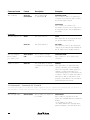
“5X Commands” – Commands 52, 55 and 56
5X commands are diagnostic tools rather than irrigation supplements. If there is a problem with a particular head, you can turn it on
with command 51, interrupt it with command 55, work on it, and then resume with command 56.
Command 51
Turn on a single station
20
##51#cc#ss##5
Turns on station ss on channel cc
for 5 minutes.
##51#21#5##
Turns on station 5 on channel 21 for five
minutes. This command differs from command 1
because:
– it only applies to one station.
– the station started by this command can be
paused, interrupted, or turned off by the other.
3 Using the Freedom System
Command name
Format
Description
Examples
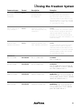
##52##
Turns off the station
previously turned on
by command 51.
##52##
The station turned on by command 51
turns off. You do not have to specify the
channel and station because Maxicom2 maintains that information. If you use this command
without first turning on a station with command
51, you hear an error beep.
Command 55
Pause the station turned
on by command 51
##55##
Interrupts the operation of a
station previously turned on by
command 51.
##55##
The station turned on by command 51 pauses.
You do not have to specify the channel and
station because Maxicom2 maintains that
information. If you use this command without
first turning on a station with command 51, you
hear an error beep.
Command 56
Resume the station
paused by command 55
##56##
Resumes the operation of the
station paused by command 55.
##56##
The station paused by command 55 resumes
operation. You do not have to specify the
channel and station because Maxicom2 maintains that information. If you use this command
without first pausing a station with command
55, you hear an error beep.
Command 71
Turn on a schedule
##71#SSSS##
Turns on schedule SSSS.
#71#105##
Turns on schedule 105.
Command 72
Turn off a schedule
##72#SSSS##
Turns off schedule SSSS.
##72#525##
Turns off schedule 525. If you omit SSSS, all
running schedules turn off, therefore, ##72##
turns off all schedules that are on.
Command 74
Advance a schedule
##74#SSSS##
Advances schedule SSSS.
##74#119##
Advances schedule 119. If you omit SSSS, all
running schedules advance, therefore, ##74##
advances all schedules that are on.
Command 75
Pause a schedule
##75#SSSS##
Interrupts the schedule SSSS.
##75#201##
Pauses schedule 201. If you omit SSSS, all
running schedules pause, therefore ##75##
pauses all schedules that are on.
Command 52
Turn off the station
turned on by
command 51
21
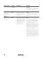
Command name
Description
Examples
Command 76
Resume a paused schedule ##76#SSSS##
Resumes an interrupted schedule.
##76#15##
Resumes schedule 15. If you omit SSSS, all
paused schedules resume, therefore ##76##
resumes all paused schedules.
Command 8
Hang up on the current
site and begin the
command sequence with
another site.
##8##
Hangs up on the site currently
on-line. Enables user to enter a
new site without re-entering
a password.
##8##
Site currently on-line is disconnected; user
enters new site for contact without re-entering
a password.
##9##
Allows Maxicom2 to stay on-line
with the current site after the user
hangs up. Maxicom2 stays on-line
with the site until the remote user
contacts it again, or until 30
minutes pass, whichever comes
first. During this time, all
passwords are locked out.
##9##
Allows the user to send commands to a site,
move to a different location in the same site,
then send more commands. For example, if
you send commands to site 8, but need to
check another part of the site before
completing the commands to site 8, enter
##9##, wait for the OK beep, then enter #
and hang up. You have 30 minutes to contact
Maxicom2 again. At the other site, call
Maxicom2 and enter your password. You will
hear the OK beep meaning you are on-line.
You can now enter commands.
Command 9
Stay on-line with the
current site after the phone
is hung up
Format
If you hear the error beep followed by a busy
signal, the window is closed. Someone at
Maxicom2 may have terminated your Freedom
contact. To determine your contact status, enter
your password and then enter ##. If you hear
one beep, you are off-line; if you hear two
beeps, you are on-line. If Maxicom2 has hung
up, contact the site in a normal way.
22
3 Using the Freedom System
2
Commands used to control Maxicom features
For the following commands listed in the table below:
• t = hour(s)
SSS = site(s)
• SSS can be 1, 2, or 3 digits.
• Anything in brackets { } is optional and unlimited in length.
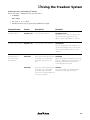
Command name
Format
Description
Examples
Command 1
Set site(s) to auto-on
##1{#SSS...}##
Sets site(s) SSS to auto-on.
##1#3#5#11#15##
Sets sites 3, 5, 11, and 15 to auto-on. If no
sites are entered, then all sites are set to
auto-on. Therefore, ##1## turns on all sites.
Sets site(s) SSS to rain shut-down.
##2#19#25##
Sets sites 19 and 25 to rain shut-down. If no
sites are entered, all sites are set to rain shutdown. Therefore, #2# sets all sites to rain
shut-down.
##6#1#t##
Opens the Freedom Time Window
for t hour(s). If t is not specified,
the window stays open for one
hour.
##6#1#5##
Opens the Freedom Time Window for the next
five hours, regardless of the closing time set in
Maxicom2. All passwords can access the
system during this time period.
##6#2#t##
Closes the Freedom Time Window ##6#2##
for t hour(s). If t is not specified,
Closes the Freedom Time Window until the
the window stays closed until
master password reopens the window.
someone uses the master password
to re-open the window.
Command 2
Set site(s) to rain shut-down ##2{#SSS...}##
Command 6
Temporarily open or
close the Freedom
Time Window
23
4 Troubleshooting
The following pages contain possible problems you may encounter and solutions.
Before calling Rain Bird, check this list. If you cannot solve the problem yourself, a
simple program called “Clemar 2” is available to confirm that the Freedom
System’s repeater, FR-200, radios, PC, cable, and telephone interface are properly
functioning. It is available by calling Rain Bird Golf Technical Services at
1.800.984.2255 and pressing 4, or faxing a request to 626.912.3616.
Problem:
The Freedom System base unit is not working correctly, not
responding properly, or not responding at all.
Solution:
• Check the power light on the base unit to be sure that the base unit
has power.
• Try to reset the base unit by entering the 676* command with the
handheld radio.
• Watch the transmit light on the base unit while resetting with the
handheld radio. It should light to indicate that it is receiving the
signal from the handheld radio.
• Check to see if you need a password to gain access to the system.
Problem:
You made service adjustments to the autopatch unit and the unit no
longer works with the Freedom System.
Solution:
While you cannot make specific adjustments to the autopatch unit
through the handheld radio or telephone, you can restore the factory
default settings:
Unplug the power cord to the base unit. The autopatch unit is factory
configured for use with the Freedom System. To return the autopatch
unit to the factory default settings, enter the 693* command from a
telephone or handheld radio. All the information in the autopatch
unit’s configuration memory will be replaced with the factory defaults
settings for a Freedom System.
Problem:
The Freedom System is locked up.
Solution:
Unplug the power cord to the base unit. Turn off both the repeater
unit and the computer completely; then turn them back on.
Problem:
Maxicom2 and the handheld radio are not communicating.
Solution:
Unplug the power cord to the base unit. Locate the switch block and
make sure that the switches are set correctly. The switch block is on the
FR-454 Repeater PC Board, the large printed circuit board. Switch 1,
3, and 5 should be in the OFF position. Switch 2, 4, and 6 should be
in the ON position. These positions enable the unit for the standard
tone of the 100 Hz CTCSS tone.
Problem:
You hear an error tone.
Solution:
• If you hear one low-pitched tone, the radio micro-controller is not
working properly.
• If you hear alternating tones (the second at a lower pitch) the
radiofrequency synthesizer is malfunctioning.
• If you get one or both of these error messages, turn off the handheld
radio and try again. If the problem still persists, send the radio in for
repair.
25
Problem:
A short warning tone sounds every 15 seconds while the handheld
radio is on.
Solution:
Recharge the battery pack. (A final longer tone means that the battery
is discharged and the radio has turned itself off.)
Problem:
The handheld radio does not work at all.
Solution:
• Make sure the battery is installed correctly.
• Change or replace the battery.
• Try the battery from a working radio. If the radio works with that
battery, the original battery may be bad.
• Try a different battery charger. The original charger could be
defective.
Problem:
The radio reception is poor.
Solution:
Move to a different location. Reception can often be improved by
moving a short distance, especially inside buildings. The radio’s range
with a standard battery pack is several miles within lines-of-sight.
Problem:
Noise or hiss sounds in the radio unit.
Solution:
Press and release the monitor button to activate the squelch function,
which will mute the noise.
Problem:
You cannot hear calls from other radios.
Solution:
• Press and release the monitor button to activate the squelch function, which will mute any noise.
• Be certain that your radio is receiving on the same frequency as the
caller is transmitting.
• Recharge the battery.
• Try the battery from a working radio. If the radio works with that
battery, the original battery may be bad.
• Change or replace the battery. If it still will not power the radio, try
a different charger. The original charger could be defective.
Problem:
Your calls cannot be heard on other radios.
Solution:
Make sure that your radio is transmitting on the receive frequency of
the radio you wish to call.
Problem:
The transmit/busy lamp does not light or is dim when you transmit.
Solution:
• Conserve the battery. Do not hold down the PTT button longer
than is necessary. Also, battery power is used while the radio is left
on to receive calls. If practical, switch off the unit.
• Make sure the battery has been fully charged.
• Change or replace the battery.
• Try the battery from a working radio. If the radio works with that
battery, the original battery may be bad.
• Try a different battery charger. The original charger could be
defective.
26
4 Troubleshooting
Problem:
You hear a busy signal when you try to contact Maxicom2.
Solution:
If you contact Maxicom2 when it is already on-line with a site, you will
hear a busy signal, which consists of many long tones, after you have
entered a site number other than 0. If you hear a busy signal, enter #*
and hang up. If someone is manually on-line, he or she will see a
message on the Maxicom2 screen indicating that a remote user wants
to get on-line and will be asked if they want to terminate their contact.
Call again in a few minutes because the manual user may have terminated contact or the automatic upload/downloads may have been
completed.
Problem:
You cannot hang up the phone.
Solution:
Before you enter #*, wait for a period of silence. The modem cannot
send a beep and listen to your commands simultaneously. Enter #
when the modem is not sending a beep. After the modem receives
the #, it will stop sending a busy signal so you can enter the * and
hang up.
Problem:
You hear a busy signal while you are already on-line.
Solution:
If you are on-line with a site and then hear the busy signal, someone at
Maxicom2 has terminated your contact. Enter #* and hang up. While
you are on-line with Maxicom2, all of the automatic uploads and
downloads will be postponed so they do not interrupt your call.
Problem:
You hear an error beep followed by a busy signal.
Solution:
If you try to contact Maxicom2 during a time that is outside the
Freedom Time Window, you will hear an error beep followed by a
busy signal after you enter your password. You are being locked out by
the Freedom Time Window, not by a manual or automatic call. Wait
until the Freedom Time Window reopens before you try to call again.
If you are already on-line and the Freedom Time Window closes, you
will not be cut off. You will be able to complete your call and hang up
as usual.
Problem:
Maxicom2 is unable to contact a site.
Solution:
If Maxicom2 is unable to contact a site, you will hear an error beep
followed by a busy signal. The modem may have been disconnected, so
do not try to call back.
27
a Appendix
Telephone interface with the Freedom System
You can contact the Freedom System and operate the Maxicom2 system from a
remote location via telephone. You may also use the handheld radio to receive and
send calls from the field through the Freedom System base unit. In order to use the
Freedom System’s full capabilities, you will need to connect a dedicated phone line
to the Freedom System base unit.
Any modem, desk telephone, answering machine, etc., should be on a separate line,
designated as telephone line “X” in fig. 8. They should not be on the same telephone line that is serving the Freedom System base unit.
A second dedicated line, designated as telephone line “Y” in fig. 8, is required for
the Freedom System base unit and to connect a telephone that you may wish to
have work with the Freedom System.
The dedicated telephone line “Y” plugs into the RJ11 socket of the Freedom
System base unit marked “Phone Line Input.” If you are also using a telephone
with the Freedom System, you will need a phone line splitter.
;ÀÀ
@;;
@@
À
;
@
À
;;À@;
@@
ÀÀ
Refer to fig. 8 for complete details on installation of the telephone line and other
related equipment.
Figure 8: Configuration of telephone interface and Freedom System
29
Using the handheld unit for telephone
operations
Answering a phone call
1. Press and hold the PTT button and press *.
2. Answer the call as you would with a normal telephone, speaking into the
microphone. Press and hold the PTT at all times when you are talking.
3. Release the PTT button in order to listen to the person on the other end of
the line.
The radio will emit a “cutover” beep when you release the PTT button. Be
sure to tell the person at the other end of the line to wait for the beep before
he or she begins to talk.
The length of a telephone call is limited to five minutes. The Freedom
System will emit two short warning beeps 20 seconds before the five minutes
expire.
Hanging up
1. Press and hold the PTT button.
2. Enter #* even though the other party has hung up.
3. If you fail to hang up, you will hear a dial tone after 10 seconds and hear a
high/low warble beep to indicate that you need to hang up.
Making a telephone call
To make a telephone call from the handheld radio unit:
1. Press and hold the PTT button.
2. Press * to get a dial tone.
3. Enter the telephone number just as you would on a normal telephone.
Remember that you must press and hold the PTT button as you enter the
number.
4. Release the PTT button, wait for the call to go through, and the other party
to answer.
5. During the phone conversation you must press and hold the PTT button on
the handheld radio unit at all times when you are talking.
6. Release the PTT button to listen to the other person when he or she is
talking.
7. The Freedom System provides a “cutover” beep when you release the PTT
button. Tell the person at the other end of the line to wait for the beep
before he or she begins to talk.
30
a Appendix
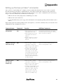
Setting up the base unit (6xx* commands)
Once you have set up the Maxicom2 computer to interact with the Freedom System, you are ready to set up the
Freedom System base unit. All the commands that are entered into the radio that control base unit operation are
know as 6xx* commands. The base unit beeps four times when it receives a 6xx* command. If you do not hear any
beeps, re-enter the command. If you still do not hear any beeps:
• Make sure the base unit is plugged into a 120 VAC power outlet.
• Make sure the radio is turned on.
• See the Troubleshooting section on pg. 25 for information on investigating possible problems with the radio’s
battery.
Begin setting up the base unit by putting it in the start-up mode (see the first command, below). You may later enter
additional base unit commands if you choose.
Command name
Command
Function
Additional comments
Base unit
start-up mode
671*
• Allows the base unit to receive
commands from the radio.
• Allows the base unit to receive
commands from a touch-tone
telephone.
• Rings the radio when incoming
telephone calls come into the
base unit.
You may place the base unit in the start-up
mode at any time by entering 671* from the
radio or a touch-tone telephone.
675*
• Allows the radio to transmit
When in this mode, the base unit will not
commands to the base unit.
answer incoming telephone calls.
• Allows the user to make outgoing
telephone calls from the radio.
• Forwards incoming telephone
calls to the radio, and the radio
will ring only once. The caller
hears multiple rings, but the radio
user will only hear the first ring.
The radio user can answer the
telephone call at any time before
the caller hangs up.
673*
• Allows the radio to transmit
When in this mode, the base unit will not
commands to the base unit.
answer incoming telephone calls.
• Allows the user to make outgoing
telephone calls from the radio.
• Forwards incoming telephone calls
to the radio and the radio rings
multiple times until the radio user
answers the call or the caller
hangs up. Both the caller and
radio user hear multiple rings.
Forward incoming
telephone calls to the
radio with one ring
Forward incoming
telephone calls to
the radio with
multiple rings
31
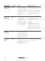
Command name
Command
Function
Additional comments
Set the base unit
to answer incoming
telephone calls
672*
• Allows the radio to transmit
commands to the base unit.
• Sets the base unit to answer
remote telephone calls which
allows the user to operate the
Maxicom2 system by remote
telephone.
• Allows outgoing calls from
the radio.
The handheld unit will not ring when the
base unit receives an incoming telephone call.
Disable remote
telephone calls
to the base unit
Reset the base unit
to its normal
(start-up) mode
674*
676*
• Allows the radio to transmit
commands to the base unit.
• Allows outgoing telephone calls
from the radio.
• Allows normal operation of the
telephone connected to the
same line as the base unit (if
applicable to your particular
base unit configuration).
If a telephone call is connected to the same line
as the base unit, the telephone will ring once,
then the base unit will answer the call. The
telephone will remain operational while the
base unit receives the call.
This command prevents the base unit from
answering incoming telephone calls, therefore
it prevents operation of the Maxicom2 by
remote telephone.
I m p o rt a n t :
To control Maxicom2 from a remote server,
enter the 672* command when you finish
with the 674* mode. If you forget to do
this, you can “call in.” Let the telephone ring
30 times and the base unit will answer the call.
This does not change the mode, however. You
still must enter the 672* command to change
the mode.
• Returns all features and options
to the default settings (the same
settings as the start-up mode).
• Terminates any action in progress
(including a telephone connection)
and reverts to the start-up mode.
Forward a call from
the base unit to
the radio.
32
679*
• Allows the base unit to forward
a call it has already answered
to the radio.
• Enables the caller and the radio
user to speak directly to each
other.
This command must be sent via telephone after
the base unit answers the call.
a Appendix
Caring for the Freedom System equipment
• The radio is not waterproof. Do not immerse it in water or expose it to
excessive moisture.
• Do not expose the radio to extreme heat such as direct sunlight in a closed
vehicle.
• Detergents, alcohol, aerosol sprays, and petroleum products can damage the
case. Clean the case using a soft cloth moistened with water.
• Fully charge the battery pack before you use the radio for the first time. Do
not fast charge a new battery; this can shorten battery life. See the handheld
radio user manual for more information.
• After the initial charge, a battery should be charged overnight after each
day of use.
• Use only the drop-in charger supplied with the Freedom System for
recharging a battery pack.
• Do not use a battery when it is not fully charged. If the battery cannot
power the radio, recharge the battery.
• Do not overcharge a battery. A standard battery should not be charged for
more than 16 hours at a time.
• If a battery does not seems to hold a charge, try to continuously charge it
for 16 hours. If it still fails, replace it.
• Once a battery has been fully charged, you may use the fast charge. Do not
fast charge a fully charged battery.
• Do not charge the battery in temperatures colder than about 45° F.
33
Optional equipment
The following optional equipment is available from your Rain Bird Distributor:
Product model No.
Description
FTX-450-01
FTX-450
5 Watt/UHF handheld radio w/DTMF pad, 11 channel
5 Watt/UHF handheld radio w/o DTMF pad, 11
channel
5 Watt/UHF handheld w/DTMF pad and w/high cap.
NiCad
5 Watt/UHF handheld w/o pad and high cap. NiCad
Watt/UHF handheld w/o pad and w/extra high cap.
NiMH
5 Watt/UHF MINI handheld radio w/DTMF pad, 11
channel
Programming charge R/B frequency per radio
Replacement 700 mAh battery for FTX
Replacement 850 mAh battery for FTX
Replacement 1100 mAh battery for FTX
Replacement 850 mAh battery for SST
Fast rate drop-in charger for handheld radio
Standard rate charger for FTX handheld radio
Cube charger for FTX and SST handheld radio
Fast rate charger for SST handheld radio
Leather holster for handheld radio
FTX-450-011K
FTX-450-0011K
FTX-450-011M 5
SST-450
RPTFP-FT
BPX-8N
BPX-8N-HC
BPX-8N-MH
BPS-6
FCP-FS
BCP-AD
BC-A
BCPS-FS
LHX-AT
LHX-A
MHX-A
CBX-A
MHS-A
RSM-3X
RHD-1X
RHD-4X
REP-2
RSM-2X
AFM-450
AFM-450S
AFS-450
AFS-450-S
RPT-PK
RPT-PCPK
34
Leather holster for standard radio w/o pad
Holster, cordura, w/nylon T-cord
Replacement belt clip (w/screws)
Holster for SST handheld radio
Speaker/microphone
Headset, single ear, in line PTT
Headset, dual ear, heavy duty
Earphone
Remote speaker microphone
Antenna, 6”, flexible, 450-470 MHz
Antenna, 3”, flexible, 450-470 MHz
Stubby antenna for SST handheld radio
Stubby antenna for SST handheld radio
Programming kit for Freedom handheld radios;
push-to-talk; programming plug
Programming kit for Freedom handheld radios;
PC compatible computer
a Appendix
Battery life and charging time
Battery life (90-5-5 duty cycle)
Model BPX-8N
Capacity
Type
BPX-8N-HC
650 mAh
NiCad
BPX-8N-MH
800 mAh
NiCad
1100 mAh
NiMH
Five watts
Battery saver enabled
Battery saver disabled
90% duty cycle
5% duty cycle
8 hrs.
4.7 hrs.
7.2 hrs.
24 mins.
9.8 hrs.
5.8 hrs.
8.8 hrs.
29 mins.
15.8 hrs.
8.7 hrs.
14.2 hrs.
47 mins.
Two watts
Battery saver enabled
Battery saver disabled
90% duty cycle
5% duty cycle
13.3 hrs.
6.2 hrs.
12 hrs.
40 mins.
16.4 hrs.
7.6 hrs.
14.8 hrs.
49 mins.
24.6 hrs.
11.4 hrs.
22.1 hrs.
1.2 hrs.
BPX-8N
650 mAh
NiCad
BPX-8N-HC
800 mAh
NiCad
BPX-8N-MH
1100 mAh
NiMH
12-14 hrs.
16-18 hrs.*
20-24 hrs.*
1.5 hrs.
1.5 hrs.
1.5 hrs.
Charging time
Model
Capacity
Type
Standard rate
charge time:
Fast rate
charge time:
*We strongly recommend the use of fast-rate chargers with these batteries.
35
FCC regulations
Telephone interface information
Specifications
Ringer equivalence: 0.7B
Universal service order code: RJ11C
DOC number: 1084 3399 A
Prohibited connections
The FP-200 autopatch unit may not be connected to
a. party telephone line
b. telephone line providing phone service
Installation requirements
All subscriber connections to the telephone system are to be made with standard
plugs and telephone company supplied jacks (or their equivalent). This set-up will
quickly disconnect in the case of a malfunction that could cause harm to the telephone network.
Customers’ responsibilities
Customers who connect this equipment directly to the public switched telephone
network (PSTN) are required to provide an approved telephone equipment coupler
between the Freedom System FP-200 autopatch unit and the PSTN.
Rights of the telephone company
When properly connected to the PSTN, the telephone company has the right to
temporarily disconnect service to any device causing harm to the system. The telephone company will, however, give prior notice if practicable. If prior notice is not
given, the company will:
1. Promptly notify you after service is disconnected.
2. Give you the opportunity to correct the situation that has caused the
disconnection.
3. Inform you of your right to file a complaint with the Federal
Communications Commission (FCC) according to the procedures set forth
in Part 68 of the FCC Rules and Regulations.
The telephone company also has the right to make changes in the facilities, equipment, operations, and procedures. If the company can foresee that the changes will
cause your equipment to be incompatible, it will give you adequate prior notice to
allow you to make the necessary changes to ensure uninterrupted service.
Further information is available in:
Part 68, Subpart B Conditions on use of terminal equipment
Part 90, Subpart O Private radio
36
Paragraph 90.476
Interconnection of fixed stations and certain mobile
stations
Paragraph 90.447
Restrictions on interconnected systems
a Appendix
If problems occur
If a problem occurs that causes interference or difficulty within the telephone
network, disconnect the Freedom System (FP-200 autopatch unit) from the telephone network by removing the modular plug from the telephone jack (Phone
Line Input) on the Freedom System base unit.
Neither you nor your distributor should attempt to repair the Freedom System base
unit, the FP-200 autopatch PC board, or the RR-454 PC board. Any unauthorized
repair may seriously affect the compliance with the rules under which the unit is
registered. Remove the unit from service and contact Rain Bird through your Rain
Bird Distributor.
FCC radio regulations
Assignment and use of 25 KHz frequency offsets
A. Frequencies separated by 25 KHz (wideband) from regularly assignable
frequencies in the 450-470 MHz band may be assigned in the land mobile
services in accordance with the following conditions:
1. All stations will be licensed as mobiles, but they may serve the functions of
base, fixed, or mobile relay stations. Such stations are limited to two watts
output power.
2. All operations should be on a secondary, non-interference basis to the
primary operations. They are not entitled to protection from such stations.
3. Where the primary channel availability is indicated in more than one service,
the frequency coordination requirements in section 90.175 apply in all
services. (See section 90.555 [a] for identification of service abbreviations.)
4. Wide area operations will not be authorized. The area of normal day-today operations is described in the application. It states the maximum
distance from a geographical center (latitude and longitude).
5. Applications for stations under this part must provide a statement of
proposed use, but are otherwise exempt from any limitation on the
number of frequencies assignable contained elsewhere in Part 90.
6. Antennas of mobile stations used as fixed stations communicating with one
or more associated stations located within 45 degrees of azimuth shall be
directional and have a front to back ratio of at least 15 dB. Except as
provided below, the height of the antenna used at any mobile station
serving as a base, fixed or mobile relay station may not exceed seven meters
(20 feet) above the ground.
•
There is no limit on the length or height above ground of any
commercially manufactured radiating transmission line when the transmission line is terminated in a non-radiating load and routed at least
seven meters (20 feet) interior to the edge of any structure or is routed
below ground level.
•
Only sea-based stations and central alarm stations operating on
frequencies allocated for central station protection operations may use
antennas mounted not more than seven meters (20 feet) above the
man-made structure, including antenna structures.
B. You can coordinate other special frequencies with Rain Bird and Cara
Enterprises (801) 278-9728.
37
Safety standards
The FCC (with its action in General Docket 79-144, March 13, 1986) has adopted
a safety standard for human exposure to radio frequency electromagnetic energy
emitted by FCC regulated equipment. We strongly recommend that you observe
these standards, especially the guidelines below:
• Do not position the radio antenna near the face, eyes, or other exposed parts
of the body while transmitting. Keep the radio vertical, two-to-three inches
away, while talking into the front panel grill.
• Do not press the PTT button unless you intend to transmit.
• Do not operate the radio equipment near electrical blasting caps or in an
explosive atmosphere.
• No repairs should be made to any of the equipment except by an authorized
repair person. Federal law prohibits you from making any internal adjustments to the transmitter or from changing transmit frequencies, unless you
are specifically designated by the licensee.
Licensing
The FCC requires you to obtain a station license for your radios before using the
equipment to transmit, but does not require you to obtain an operating license or
permit. The station licensee is responsible for ensuring that the transmitter power,
frequency, and deviation are within the limits specified by the station license.
The station licensee is also responsible for proper operation and maintenance of his
or her radio equipment. This responsibility includes checking the transmitter
frequency and deviation periodically using the appropriate methods.
In order to receive an FCC license for either VHF or UHF frequencies, you must
submit an FCC application form. An FCC license application packet is included
with the Freedom System.
License application
See the included packet.
Service information
If your Freedom System equipment (including the Freedom System base unit,
handheld radio, or other auxiliary equipment) fails to operate properly and needs to
be repaired, contact your Rain Bird Distributor from whom you purchased the
equipment. In most cases, the Rain Bird Distributor will be able to determine the
cause of the problem and take the necessary action to correct it. If he is unable to
correct the problem, he will then contact Rain Bird for assistance.
38
PN 633888