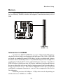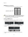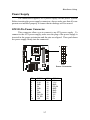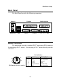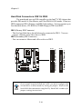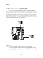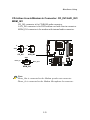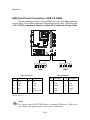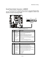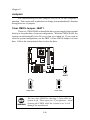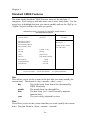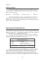
1
MSI MICRO-STAR INTERNATIONAL MS-6534 Micro ATX Mainboard Version 1.0 G52-MA00417 i Manual Rev: 1.0 Release Date: August 2001 FCC-B Radio Frequency Interference Statement This equipment has been tested and found to comply with the limits for a class B digital device, pursuant to part 15 of the FCC rules. These limits are designed to provide reasonable protection against harmful interference when the equipment is operated in a commercial environment. This equipment generates, uses and can radiate radio frequency energy and, if not installed and used in accordance with the instruction manual, may cause harmful interference to radio communications. Operation of this equipment in a residential area is likely to cause harmful interference, in which case the user will be required to correct the interference at his own expense. Notice 1 The changes or modifications not expressly approved by the party responsible for compliance could void the user's authority to operate the equipment. Notice 2 Shielded interface cables and A.C. power cord, if any, must be used in order to comply with the emission limits. VOIR LA NOTICE D'INSTALLATION AVANT DE RACCORDER AU RESEAU. Micro-Star International MS-6534 Tested to comply with FCC Standard For Home or Office Use ii Edition August 2001 Copyright Notice The material in this document is the intellectual property of MICROSTAR INTERNATIONAL. We take every care in the preparation of this document, but no guarantee is given as to the correctness of its contents. Our products are under continual improvement and we reserve the right to make changes without notice. Trademarks All trademarks used in this manual are the property of their respective owners. Intel and Pentium are registered trademarks of Intel Corporation. PS/2 and OS/2 are registered trademarks of IBM Corporation. Windows 98/2000/ME and Windows NT are registered trademarks of Microsoft. Netware is a registered trademark of Novell. Award is a registered trademark of Award Software Inc. AMI is a registered trademark of American Megatrends. Inc. Revision History Revision 1.0 Revision History First Release Date August 2001 iii Safety Instructions 1. 2. 3. 4. 5. Always read the safety instructions carefully. Keep this User’s Manual for future reference. Keep this equipment away from humidity. Lay this equipment on a reliable flat surface before setting it up. The openings on the enclosure are for air convection hence protects the equipment from overheating. DO NOT COVER THE OPENINGS. 6. Make sure the voltage of the power source and adjust properly 110/220V before connecting the equipment to the power inlet. 7. Place the power cord such a way that people can not step on it. Do not place anything over the power cord. 8. Always Unplug the Power Cord before inserting any add-on card or module. 9. All cautions and warnings on the equipment should be noted. 10. Never pour any liquid into the opening that could damage or cause electrical shock. 11. If any of the following situations arises, get the equipment checked by a service personnel: • The power cord or plug is damaged • Liquid has penetrated into the equipment • The equipment has been exposed to moisture • The equipment has not work well or you can not get it work according to User’s Manual. • The equipment has dropped and damaged • If the equipment has obvious sign of breakage 12. DO NOT LEAVE THIS EQUIPMENT IN AN ENVIRONMENT UNCONDITIONED, STORAGE TEMPERATURE ABOVE 600 C (1400F), IT MAY DAMAGE THE EQUIPMENT. CAUTION: Danger of explosion if battery is incorrectly replaced. Replace only with the same or equivalent type recommended by the manufacturer. iv Contents Chapter 1. Introduction ............................................................... 1-1 Mainboard Specification ............................................................ 1-2 Mainboard Layout ..................................................................... 1-4 Quick Components Guide ......................................................... 1-5 Key Features ............................................................................ 1-6 Chapter 2. Hardware Setup ........................................................ 2-1 Central Processing Unit: CPU ................................................... 2-2 Installing the CPU ............................................................... 2-2 Installing the CPU Fan ........................................................ 2-3 CPU Core Speed Derivation Procedure ................................ 2-4 Memory .................................................................................... 2-5 Introduction to SDRAM ....................................................... 2-5 DIMM Modules Combination ............................................... 2-6 Installing DIMM Modules ..................................................... 2-6 Power Supply ............................................................................ 2-7 ATX 20-Pin Power Connector............................................... 2-7 ATX 12V Power Connector: JPW1 ....................................... 2-8 Back Panel ............................................................................... 2-9 Mouse Connector ................................................................ 2-9 Keyboard Connector ......................................................... 2-10 USB Connectors ............................................................... 2-10 Parallel Port Connector ..................................................... 2-11 Serial Port Connectors: COM A & COM B ........................ 2-12 Joystick/Midi Connector .................................................... 2-12 Audio Port Connectors ...................................................... 2-12 Connectors ............................................................................. 2-13 Floppy Disk Drive Connector: FDD1 .................................. 2-13 Hard Disk Connectors: IDE1 & IDE2 ................................. 2-14 Case Connectors: F_P1 & F_P2 ....................................... 2-15 v Power Saving Switch Connector: JGS1 ............................. 2-19 Wake On LAN Connector: JWOL1 .................................... 2-19 Wake On Ring Connector: JMDM1 (Optional) ................... 2-20 IrDA Infrared Module Connectors: IR1 & IR2 ...................... 2-21 Fan Power Connectors: C_FAN1/S_FAN1 ......................... 2-22 CD-In/Aux Line-In/Modem-In Connector: CD_IN1/AUX_IN1/ MDM_IN1 .......................................................................... 2-23 USB Front Panel Connectors: USB1 & USB2 ................... 2-24 Front Panel Audio Connector: JAUDIO1 ............................ 2-25 Jumpers .................................................................................. 2-26 Clear CMOS Jumper: JBAT1 ............................................. 2-26 Slots ....................................................................................... 2-27 AGP (Accelerated Graphics Port) Slot .............................. 2-27 PCI Slots .......................................................................... 2-27 CNR (Communication Network Riser) Slot ........................ 2-27 PCI Interrupt Request Routing ........................................... 2-28 Chapter 3. AWARD® BIOS Setup ................................................ 3-1 Entering Setup .......................................................................... 3-2 Control Keys ............................................................................. 3-2 Getting Help .............................................................................. 3-3 The Main Menu ......................................................................... 3-4 Standard CMOS Features ......................................................... 3-6 Advanced BIOS Features .......................................................... 3-9 Advanced Chipset Features .................................................... 3-13 Integrated Peripherals ............................................................. 3-15 Power Management Setup ...................................................... 3-19 PnP/PCI Configurations ........................................................... 3-23 PC Health Status .................................................................... 3-25 Frequency/Voltage Control ...................................................... 3-26 Load Fail-Safe/Optimized Defaults .......................................... 3-28 vi Set Supervisor/User Password ................................................ 3-30 Save & Exit Setup ................................................................... 3-32 Exit Without Saving ................................................................. 3-33 Chapter 4. AMI® BIOS Setup ...................................................... 4-1 Entering Setup .......................................................................... 4-2 Selecting the First Boot Device ................................................. 4-2 Control Keys ............................................................................. 4-3 Getting Help .............................................................................. 4-4 The Main Menu ......................................................................... 4-5 Standard CMOS Setup ............................................................. 4-7 BIOS Features Setup ................................................................ 4-9 Chipset Features Setup .......................................................... 4-12 Power Management Setup ...................................................... 4-14 PNP/PCI Configuration ............................................................ 4-18 Integrated Peripherals ............................................................. 4-20 Hardware Monitor Setup .......................................................... 4-24 Load Optimal/Fail Safe Defaults .............................................. 4-26 Supervisor/User Password ...................................................... 4-28 IDE HDD AUTO Detection ....................................................... 4-30 Save & Exit Setup ................................................................... 4-31 Exit Without Saving ................................................................. 4-32 Appendix A. Using 4-/6-channel Audio Function ..................... A-1 Installing C-Media Drivers ......................................................... A-2 Hardware Configuration ............................................................ A-2 Software Configuration .............................................................. A-3 Glossary ............................................................................................ I vii Introduction 1 Chapter 1. Introduction Thank you for purchasing the MS-6534 Micro-ATX motherboard. The mainboard, based on Intel® Brookdale (82845) & 82801BA chipsets, is a high-performance computer mainboard designed for Intel® Pentium® 4 processor in the 478 pin package that provides a high-end and professional desktop platform solution. This chapter includes the following topics: Mainboard Specification Mainboard Layout Quick Components Guide Key Features 1-1 1-2 1-4 1-5 1-6 Chapter 1 Mainboard Specification CPU z Supports Socket478 for Intel® Pentium 4 (FC-PGA2) processor z Supports 1.3GHz, 1.4GHz and up to 2.xGHz Chipset z Intel® Brookdale chipset - AGP 4x/2x universal slot - Supports 100MHz FSB - Supports 400MHz Intel NetBurst micro-architecture bus z Intel® ICH2 chipset (360 BGA) - AC’97 Controller Integrated - 2 full IDE channels, up to ATA100 - Low pin count interface for Winbond SIO Main Memory z Supports two 168-pin DIMM sockets z Supports 32MB to 1GB memory using 512Mbit technology z Max. memory size: 2GB Note: As 845 chipset does not properly support the PC100 memory, it is strongly recommended to install PC133 DIMM modules for better system performance and stability. We do not guarantee the system stability when installing PC 100 DIMM modules. Slots z One AGP (Accelerated Graphics Port) 2x/4x 1.5V slot z Three PCI 2.2 32-bit Master PCI Bus slots z Supports 3.3v/5v PCI bus Interface z One CNR slot On-Board IDE z An IDE controller on the ICH2 chipset provides IDE HDD/CD-ROM with PIO, Bus Master and Ultra DMA66/100 operation modes. z Can connect up to four IDE devices. On-Board Peripherals z On-Board Peripherals include: 1-2 Introduction - 1 floppy port supports 1 FDD with 360K, 720K, 1.2M, 1.44M and 2.88Mbytes. - 2 serial ports (COMA / COMB) - 1 parallel port supports SPP/EPP/ECP mode - 4 USB ports (Rear * 2 / Front * 2) - PS/2 Keyboard/Mouse connector - 1 Line-In/Line-Out/Mic-In/Game port H/W Audio (Optional) z C-mediaCMI8738-6CH-LX z Supports 6 channel Audio z AC97 2.1 compliant S/W Audio z 2-channel Audio Codec z 4-channel Audio Codec (Optional) z AC97 2.1 compliant BIOS z The mainboard BIOS provides “Plug & Play” BIOS which detects the peripheral devices and expansion cards of the board automatically. z The mainboard provides a Desktop Management Interface (DMI) function which records your mainboard specifications. Dimension z Micro ATX Form Factor (24.4cm x 22.4cm) Mounting z 6 mounting holes 1-3 Chapter 1 Mainboard Layout USB ports FDD1 C_FAN1 ATX Power Supply Top : mouse Bottom: keyboard Bottom: Line-Out Line-In Mic IDE 2 AUX_IN1 Top : Game port CD_IN1 DIMM 1 Bottom: COM A COM B DIMM 2 Top : Parallel Port Intel Brookdale Chipset JPW1 I/O Chip IDE 1 AGP Slot MDM_IN1 BATT + JAUDIO1 CNR MS-6534 Micro-ATX Mainboard 1-4 USB2 F_P2 JGS1 FWH USB1 IR2 F_P1 PCI Slot 3 JBAT1 PCI Slot 2 JMDM1 (Optional) IR1 Audio Codec S_FAN1 ICH2 JWOL1 H/W Audio (Optional) PCI Slot 1 Introduction Quick Components Guide Component Function Reference DIMM1~2 Installing DIMM modules See p. 2-5~2-6 Socket 478 Installing CPU See p. 2-2~2-4 C_FAN1 Connecting to CPU FAN See p. 2-22 S_FAN1 Connecting to SYSTEM FAN See p. 2-22 ATX Power Supply Installing power supply See p. 2-7 JPW1 Connecting to 12V ATX power supply See p. 2-8 IDE1& IDE2 Connecting to IDE hard disk drives See p. 2-14 FDD1 Connecting to floppy disk drive See p. 2-13 USB1/2 Connecting to USB interfaces See p. 2-24 PCI Slot 1~3 Installing PCI expansion cards See p. 2-27 AGP Slot Installing AGP cards See p. 2-27 CNR Slot Installing CNR cards See p. 2-27 JMDM1 (Optional) Connecting to modem module See p. 2-20 JWOL1 Connecting to LAN module See p. 2-19 JBAT1 Clearing CMOS data See p. 2-26 F_P1/2 Connecting to case See p. 2-15 JGS1 Connecting to power saving switch See p. 2-19 IR1/2 Connecting to IR modules See p. 2-21 JAUDIO1 Connecting to front audio connectors See p. 2-25 1-5 Chapter 1 Key Features z z z z z z z z z z z Micro-ATX Form Factor CPU: Socket 478 for Intel® Pentium® 4 Processors Memory: 2 SDRAM DIMMs Slot: 1 AGP slot, 1 CNR slot, 3 PCI slots I/O: 2 serial ports, 1 parallel port, 4 USB 1.1 ports, 1 floppy port, 2 IrDA connectors, 1 Audio/Game port PC2001 Compliant LAN Wake up Function Modem (External/Internal) Ring Wake up Function (Internal Ring Wake up feature is Optional) STR (Suspend to RAM) Suspend to Disk Audio: Chip integrated 1-6 Hardware Setup Chapter 2. Hardware Setup 2 Hardware Setup This chapter provides you with the information about hardware setup procedures. While doing the installation, be careful in holding the components and follow the installation procedures. For some components, if you install in the wrong orientation, the components will not work properly. Use a grounded wrist strap before handling computer components. Static electricity may damage the components. This chapter contains the following topics: Central Processing Unit (CPU) Memory Power Supply Back Panel Connectors Jumpers Slots 2-1 2-2 2-5 2-7 2-9 2-13 2-26 2-27 Chapter 2 Central Processing Unit: CPU The mainboard supports Intel® Pentium® 4 processor. The mainboard uses a CPU socket called Socket 478 for easy CPU installation. Make sure that the CPU has a Heat Sink and a cooling fan attached to prevent overheating. If you do not find the Heat Sink and cooling fan, contact your dealer or purchase them before turning on the computer. Open Lever Installing the CPU 1. Pull the lever sideways away Sliding Plate from the socket. Then, raise the lever up to a 90-degree angle. 2. Look for the dot/cut edge. Dot / Cut edge The dot/cut edge should point towards the lever pivot. The CPU will only fit in the correct orientation. Close Lever 3. Hold the CPU down firmly, and then close the lever to complete the installation. WARNING! Overheating will seriously damage the CPU and system, always make sure the cooling fan can work properly to protect the CPU from overheating. 2-2 Hardware Setup Installing the CPU Fan As processor technology pushes to faster speeds and higher performance, thermal management becomes increasingly important. To dissipate heat, you need to attach the CPU cooling fan and heatsink on top of the CPU. Follow the instructions below to install the Heatsink/Fan: 1. Locate the CPU and its retention 2. Position the heatsink onto the mechanism on the motherboard. retention mechanism. Retention Mechanism 3. Mount the fan on top of the 4. Press the two levers down to heatsink. Press down the fan until its four clips get locked in the holes of the retention mechanism. fasten the fan. Each lever can be pressed down in only ONE direction. Levers 2-3 Chapter 2 5. Connect the fan power cable to the 3-pin fan power connector on the board. fan power cable CPU Core Speed Derivation Procedure If CPU Clock Core/Bus ratio then CPU core speed WARNING! = = = = = 100MHz 14 Host Clock x Core/Bus ratio 100MHz x 14 1.4GHz Overclocking This motherboard is designed to support overclocking. However, please make sure your components are able to tolerate such abnormal setting, while doing overclocking. Any attempt to operate beyond product specifications is not recommended. We do not guarantee the damages or risks caused by inadequate operation or beyond product specifications. 2-4 Hardware Setup Memory The mainboard provides 2 sockets for 168-pin SDRAM DIMM (Double In-Line Memory Module) modules and supports a maximum memory size of 2GB. DIMM Slots (DIMM 1~2) Introduction to SDRAM Synchronous DRAM (SDRAM) is a type of dynamic RAM memory chip that has been widely used starting in the latter part of the 1990s. SDRAMs are based on standard dynamic RAM chips, but have sophisticated features that make them considerably faster. First, SDRAM chips are fast enough to be synchronized with the CPU's clock, which eliminates wait states. Second, the SDRAM chip is divided into two cell blocks, and data is interleaved between the two so that while a bit in one block is being accessed, the bit in the other is being prepared for access. This allows SDRAM to burst the second and subsequent, contiguous characters at a rate of 10ns, compared to 60ns for the first character. SDRAM provides 800 MBps or 1 GBps data transfer depending on whether the bus is 100MHz or 133MHz. 2-5 Chapter 2 DIMM Modules Combination You can install memory modules in any combination as follows: S (Single Side): 32MB ~ 512MB D (Double Side): 64MB ~ 1GB DIMM 1 DIMM 2 S/D -- -- S/D S D D S S S D D Note: As 845 chipset does not properly support the PC100 memory, it is strongly recommended to install PC133 DIMM modules for better system performance and stability. We do not guarantee the system stability when installing PC 100 DIMM modules. Installing DIMM Modules 1. The DIMM slot has 2 Notch Keys “VOLT and DRAM”, so the DIMM memory module can only fit in one direction. Front View Rear View 2. Insert the DIMM memory module vertically into the DIMM slot. Then push it in. DRAM VOLT 3. The plastic clip at each side of the DIMM slot will automatically close. 2-6 Hardware Setup Power Supply The mainboard supports ATX power supply for the power system. Before inserting the power supply connectors, always make sure that all components are installed properly to ensure that no damage will be caused. ATX 20-Pin Power Connector This connector allows you to connect to an ATX power supply. To connect to the ATX power supply, make sure the plug of the power supply is inserted in the proper orientation and the pins are aligned. Then push down the power supply firmly into the connector. 10 20 1 11 ATX Power Connector PIN SIGNAL PIN SIGNAL 1 2 3 4 5 6 7 8 9 10 3.3V 3.3V GND 5V GND 5V GND PW_OK 5V_SB 12V 11 12 13 14 15 16 17 18 19 20 3.3V -12V GND PS_ON GND GND GND -5V 5V 5V 2-7 Chapter 2 ATX 12V Power Connector: JPW1 Attaching the ATX power supply to the connector is helpful for offering sufficient voltage to Pentium 4 CPU. 4 2 3 1 JPW1 PIN 1 2 3 4 SIGNAL GND GND 12V 12V 2-8 Hardware Setup Back Panel The Back Panel provides the following connectors: Parallel Mouse Keyboard USB COM A Midi/Joystick COM B L-out L-in MIC Mouse Connector The mainboard provides a standard PS/2® mouse mini DIN connector for attaching a PS/2® mouse. You can plug a PS/2® mouse directly into this connector. Pin Definition 6 5 4 3 2 1 PS/2 Mouse (6-pin Female) PIN SIGNAL DESCRIPTION 1 2 3 4 5 6 Mouse DATA NC GND VCC Mouse Clock NC Mouse DATA No connection Ground +5V Mouse clock No connection 2-9 Chapter 2 Keyboard Connector The mainboard provides a standard PS/2® keyboard mini DIN connector for attaching a PS/2® keyboard. You can plug a PS/2® keyboard directly into this connector. Pin Definition 6 5 4 3 2 1 PS/2 Keyboard (6-pin Female) PIN 1 2 3 4 5 6 SIGNAL Keyboard DATA NC GND VCC Keyboard Clock NC DESCRIPTION Keyboard DATA No connection Ground +5V Keyboard clock No connection USB Connectors The mainboard provides a UHCI (Universal Host Controller Interface) Universal Serial Bus root for attaching USB devices such as keyboard, mouse or other USB-compatible devices. You can plug the USB device directly into ths connector. USB Port Description 1 2 3 4 5 6 7 8 USB Ports PIN 1 2 3 4 5 6 7 8 SIGNAL VCC -Data 0 +Data0 GND VCC -Data 1 +Data 1 GND 2-10 DESCRIPTION +5V Negative Data Channel 0 Positive Data Channel 0 Ground +5V Negative Data Channel 1 Positive Data Channel 1 Ground Hardware Setup Parallel Port Connector The mainboard provides a 25-pin female centronic connector for LPT. A parallel port is a standard printer port that supports Enhanced Parallel Port (EPP) and Extended Capabilities Parallel Port (ECP) mode. 13 1 25 14 Pin Definition PIN 1 2 3 4 5 6 7 8 9 10 11 12 13 14 15 16 17 18 19 20 21 22 23 24 25 SIGNAL STROBE DATA0 DATA1 DATA2 DATA3 DATA4 DATA5 DATA6 DATA7 ACK# BUSY PE SELECT AUTO FEED# ERR# INIT# SLIN# GND GND GND GND GND GND GND GND 2-11 DESCRIPTION Strobe Data0 Data1 Data2 Data3 Data4 Data5 Data6 Data7 Acknowledge Busy Paper End Select Automatic Feed Error Initialize Printer Select In Ground Ground Ground Ground Ground Ground Ground Ground Chapter 2 Serial Port Connectors: COM A & COM B The mainboard has two 9-pin male DIN connectors for serial port COM A and COM B. You can attach a serial mouse or other serial devices. Pin Definition 1 2 3 4 5 6 7 8 9 9-Pin Male DIN Connectors PIN SIGNAL DESCRIPTION 1 2 3 4 5 6 7 8 9 DCD SIN SOUT DTR GND DSR RTS CTS RI Data Carry Detect Serial In or Receive Data Serial Out or Transmit Data Data Terminal Ready) Ground Data Set Ready Request To Send Clear To Send Ring Indicate Joystick/Midi Connector You can connect a joystick or game pad to this connector. Audio Port Connectors Line Out is to connect speakers or headphones. Line In is a connector for external CD player, Tape player or other audio devices. Mic is used to connect to a microphone. Line Out TIP Line In MIC The mainboard provides 6-channel audio support and can turn the rear audio connectors from 2-channel to 4-/6-channel audio. For more information, refer to Appendix A. Using 4-/6-channel Audio Function. 2-12 Hardware Setup Connectors The mainboard provides connectors to connect FDD, IDE HDD, case, modem, LAN, USB Ports, IR module and CPU/System FAN. Floppy Disk Drive Connector: FDD1 The mainboard provides a standard floppy disk drive connector that supports 360KB, 720KB, 1.2MB, 1.44MB and 2.88MB floppy disk types. 34 33 2 1 FDD1 2-13 Chapter 2 Hard Disk Connectors: IDE1 & IDE2 The mainboard uses an IDE controller on the Intel® ICH2 chipset that provides PIO mode 0-4, Bus Master, and Ultra DMA 66/100 modes. It has two HDD connectors IDE1 (Primary) and IDE2 (Secondary). You can connect up to four hard disk drives, CD-ROM or 120MB Floppy to IDE1 and IDE2. IDE1 (Primary IDE Connector) - The first hard disk drive should always be connected to IDE1. You can connect a Master and a Slave drive to IDE1. IDE2 (Secondary IDE Connector) - You can connect a Master and a Slave drive to IDE2. 40 39 2 1 TIP Primary IDE Connector Secondary IDE Connector 40 39 2 1 If you install two hard disks on cable, you must configure the second drive to Slave mode by setting its jumper. Refer to the hard disk documentation supplied by hard disk vendors for jumper setting instructions. 2-14 Hardware Setup Case Connectors: F_P1 & F_P2 The case connector block F_P1 allows you to connect to the Power Switch, Reset Switch, Speaker, Power LED, Keylock and HDD LED on the case. The other case connector block F_P2 is compliant to Intel Front Panel I/O Connectivity Design Guide and can connect to the the Power Switch, Reset Switch, Power LED and HDD LED on the case. 18 9 Reset Switch 15 Speaker Power Switch + Power LED 14 Buzzer (short pin) + HDD LED 1 10 Keylock F_P1 10 9 Reserved Power Switch Reset Switch Power LED HDD LED F_P1 Pin Definition 2 1 F_P2 F_P2 Pin Definition Pin Description Pin Description 1 Keylock 10 Keylock 2 NC 11 NC Pin Description Pin Description 3 HDD_LED+ 12 HDD_LED- 1 *HDD_LED+ 2 PWR_LED G 4 GND 13 CASE_SPK 3 HDD_LED- 4 PWR_LED Y 5 PWR_LED Y 14 CASE_SPK 5 RESET- 6 PWR_SW+ 6 PWR_LED G 15 CASE_SPK 7 RESET+ 8 PWR_SW- 7 PWR_SW+ 16 CASE_SPK 9 RSVD_DNU 10 NC 8 PWR_SW- 17 RESET+ 9 NC 18 RESET- * Hard disk LED pullup (330 ohm) to +5V 2-15 Chapter 2 Power Switch Connect to a 2-pin push button switch. Reset Switch Reset switch is used to reboot the system rather than turning the power ON/ OFF. Avoid rebooting while the HDD is working. You can connect the Reset switch from the system case to this pin. Power LED (F_P1) The Power LED is lit while the system power is on. There are three types of LEDs you can connect from the system case to the pin: 2-pin single color power LED: Connected to pin 5 & 6. The power LED is not able to change its color. You can only choose Blinking in the BIOS utility for the power LED to indicate the suspend/sleep mode. LED Status Description Steady Green The system is in the full-on mode. Blinking The system enters the suspend/sleep mode. 2-pin/3-pin dual color power LED: 2-pin LED is connected to pin 5 & 6. 3-pin LED is connected to pin 4, 5 & 6. The dual color power LED is able to change its color to indicate different system states. Therefore, you can select either Blinking or Dual (color) for the power LED to show the suspend/sleep mode. z When you select Blinking in the BIOS utility: LED Status Description Steady Green The system is in the full-on mode. Blinking The system enters the suspend/sleep mode. 2-16 Hardware Setup z When you select Dual (color) in the BIOS utility: LED Status Description Steady Green The system is in the full-on mode. Steady Orange The system enters the suspend/sleep mode. Power LED (F_P2) The Power LED is lit while the system power is on. There are two types of LEDs you can connect from the system case to the pin: 2-pin single color power LED: The power LED is not able to change its color. Therefore, you can only choose Blinking in the BIOS utility for the power LED to indicate the suspend/sleep mode. LED Status Description Steady Green The system is in the full-on mode. Blinking The system enters the suspend/sleep mode. 2-pin dual color power LED: The 2-pin power LED can change its color to indicate different system states. Therefore, you can select either Blinking or Dual (color) for the power LED to show the suspend/sleep mode. z z When you select Blinking: LED Status Description Steady Green The system is in the full-on mode. Blinking The system enters the suspend/sleep mode. When you select Dual (color): LED Status Description Steady Green The system is in the full-on mode. Steady Orange The system enters the suspend/sleep mode. 2-17 Chapter 2 HDD LED HDD LED shows the activity of a hard disk drive connected to the IDE1 or IDE2 connector. Avoid turning the power off while the HDD is working. You can connect the HDD LED from the system case to this pin. Speaker (F_P1 only) Speaker from the system case is connected to this pin. If on-board Buzzer is available, then: Short pin 14-15: On-board Buzzer Enabled. Open pin 14-15: On-board Buzzer Disabled. Keylock (F_P1 only) Keylock allows you to disable the keyboard for security purpose. You can connect the keylock to this connector. 2-18 Hardware Setup Power Saving Switch Connector: JGS1 Attach a power saving switch to this connector. Pressing the switch once will have the system enter the sleep/suspend state. Press any key to wake up the system. ExtSMI# GND 1 JGS1 Wake On LAN Connector: JWOL1 This connector allows you to connect to a LAN card with Wake On LAN function. You can wake up the computer via remote control through a local area network. 1 5VSB GND MP_WAKEUP JWOL1 2-19 Chapter 2 Wake On Ring Connector: JMDM1 (Optional) This connector allows you to connect to a modem card with Wake On Ring function. The connector will power up the system when a signal is received through the modem card. 5VSB NC MDM_WAKEUP GND 1 NC JMDM1 Note: Modem wake-up signal is active “low”. 2-20 Hardware Setup IrDA Infrared Module Connectors: IR1 & IR2 These connectors allow you to connect to IrDA Infrared modules. You must configure the setting through the BIOS setup to use the IR function. The difference between IR1 & IR2 is that IR2 is compliant to Intel Front Panel I/O Connectivity Design Guide. 1 IR1 6 5 2 1 IR2 IR2 Pin Definition Pin Signal 1 Not assigned 2 NC 3 VCC 4 GND 5 IRTX 6 IRRX IR1 Pin Definition Pin Signal 1 VCC 2 NC 3 IRRX 4 GND 5 IRTX 2-21 Chapter 2 Fan Power Connectors: C_FAN1/S_FAN1 The C_FAN1 (processor fan) and S_FAN1 (system fan) support system cooling fan with +12V. It supports three-pin head connector. When connecting the wire to the connectors, always take note that the red wire is the positive and should be connected to the +12V, the black wire is Ground and should be connected to GND. If the mainboard has a System Hardware Monitor chipset on-board, you must use a specially designed fan with speed sensor to take advantage of the CPU fan control. SENSOR +12V GND C_FAN1 SENSOR +12V GND S_FAN1 Note: 1. Always consult the vendor for proper CPU cooling fan. 2. CPU Fan supports the fan control. You can install the PC Alert utility that will automatically control the CPU Fan speed according to the actual CPU temperature. 2-22 Hardware Setup CD-In/Aux Line-In/Modem-In Connector: CD_IN1/AUX_IN1/ MDM_IN1 CD_IN1 connector is for CD-ROM audio connector. AUX_IN1 connector is for DVD add-on card with Line-in connector. MDM_IN1 connector is for modem with internal audio connector. R R GND GND L L CD_IN1 AUX_IN1 GND Phone_In Mono_Out MDM_IN1 Note: Mono_Out is connected to the Modem speaker-out connector. Phone_In is connected to the Modem Microphone-In connector. 2-23 Chapter 2 USB Front Panel Connectors: USB1 & USB2 The mainboard provides two Front USB (Universal Serial Bus) pin headers that allow you to connect optional USB ports for front panel. Different from USB1, USB2 is compliant to Intel Front Panel I/O Connectivity Design Guide. 2 1 10 2 9 1 10 9 USB1 USB2 USB1 Pin Definition USB2 Pin Definition Pin Description Pin Description Pin Description Pin 1 VCC 2 VCC 1 VCC 2 Description GND 3 USB3- 4 USB2- 3 USB2- 4 GND 5 USB3+ 6 USB2+ 5 USB2+ 6 USB3+ 7 GND 8 GND 7 GND 8 USB3- 9 NC 10 *USB_FP_OC0 9 GND 10 VCC *USB_FP_OC0 is Front Panel USB Overcurrent signal (Ports 2 & 3) Note: You can use only ONE USB header to connect USB ports. Make sure you choose the appropriate one for your USB ports. 2-24 Hardware Setup Front Panel Audio Connector: JAUDIO1 You can connect an optional audio connector to the Front Panel Audio Header. Pin number 1to 10 of the audio pin header is compliant to Intel Front Panel I/O Connectivity Design Guide. 2 1 10 20 9 19 JAUDIO1 JAUDIO1 Pin Definition (1~10) Pin Signal 1 AUD_MIC Description Front Panel Microphone input signal 2 3 4 5 6 7 8 9 AUD_GND AUD_MIC_BIAS AUD_VCC AUD_FPOUT_R AUD_RET_R HP_ON NC AUD_FPOUT_L Ground used by Analog Audio Circuits Microphone Power Filtered +5V used by Analog Audio Circuits Right Channel Audio signal to Front Panel Right Channel Audio signal Return from Front Panel RSVD for future use to control Headphone Amplifier No Connection Left Channel Audio signal to Front Panel 10 AUD_RET_L Left Channel Audio signal Return from Front Panel JAUDIO1 Pin Definition (11~20) Pin Signal 11 AUD_MIC Description Front Panel Microphone input signal 12 13 14 15 16 17 18 19 AUD_GND AUD_FPOUT_R AUD_RET_R AUD_FPOUT_L AUD_RET_L AUD_GND NC LINE-IN-R Ground used by Analog Audio Circuits Right Channel Audio signal to Front Panel Right Channel Audio signal Return from Front Panel Left Channel Audio signal to Front Panel Left Channel Audio signal Return from Front Panel Ground used by Analog Audio Circuits No Connection Line in Right 20 LINE-IN-L Line in Left 2-25 Chapter 2 Jumpers The motherboard provides jumpers for you to set the computer’s function. This section will explain how to change your motherboard’s function through the use of jumpers. Clear CMOS Jumper: JBAT1 There is a CMOS RAM on board that has a power supply from external battery to keep the data of system configuration. With the CMOS RAM, the system can automatically boot OS every time it is turned on. If you want to clear the system configuration, use the JBAT1 (Clear CMOS Jumper ) to clear data. Follow the instructions below to clear the data: 1 JBAT1 3 3 1 1 keep data WARNING! clear data You can clear CMOS by shorting 2-3 pin while the system is off. Then return to 1-2 pin position. Avoid clearing the CMOS while the system is on; it will damage the mainboard. 2-26 Hardware Setup Slots The motherboard provides three 32-bit Master PCI Bus Slots, one AGP and one CNR slot. AGP Slot PCI Slots CNR Slot AGP (Accelerated Graphics Port) Slot The AGP slot allows you to insert the AGP 1.5V graphics card. AGP is an interface specification designed for the throughput demands of 3D graphics. It introduces a 66MHz, 32-bit channel for the graphics controller to directly access main memory and provides three levels of throughputs: 1x (266Mbps), 2x (533Mbps) and 4x (1.07Gbps). PCI Slots Three PCI slots allow you to insert the expansion cards to meet your needs. When adding or removing expansion cards, make sure that you unplug the power supply first. Meanwhile, read the documentation for the expansion card to make any necessary hardware or software settings for the expansion card, such as jumpers, switches or BIOS configuration. CNR (Communication Network Riser) Slot The CNR slot allows you to insert the CNR expansion cards. CNR is a specially designed network, audio, or modem riser card for ATX family motherboards. Its main processing is done through software and controlled by the motherboard’s chipset. 2-27 Chapter 2 PCI Interrupt Request Routing The IRQ, abbreviation of interrupt request line and pronounced I-R-Q, are hardware lines over which devices can send interrupt signals to the microprocessor. The “AGP/PCI/USB/AC’97 codec” IRQ pins are typically connected to the PCI bus INTA#-INTH# pins as follows: Order 1 Order 2 Order 3 Order 4 AGP INT A# INT B# PCI Slot 1 INT A# INT B# INT C# INT D# PCI Slot 2 INT B# INT C# INT D# INT A# PCI Slot 3 INT C# INT D# INT A# INT B# USB-1 INT D# USB-2 INT H# AC97 INT B# AGP & PCI Slot 1 shared. PCI Slot 2 & AC97 shared. PCI Slot 1~3: Bus Master 2-28 AWARD® BIOS Setup Chapter 3. AWA R D ® B I O S Setup 3 AWARD® BIOS Setup If your motherboard comes with the AWARD® BIOS ROM, read this chapter for an overview of the Award® BIOS settings. AWARD® BIOS ROM provides a Setup utility for users to modify the basic system configuration. The information is stored in a battery-backed CMOS RAM so it retains the Setup information when the power is turned off. The chapter contains the following topics: Entering Setup Control Keys Getting Help The Main Menu Standard CMOS Features Advanced BIOS Features Advanced Chipset Features Integrated Peripherals Power Management Setup PnP/PCI Configurations PC Health Status Frequency/Voltage Control Load Fail-Safe/Optimized Defaults Set Supervisor/User Password Save & Exit Setup Exit Without Saving 3-1 3-2 3-2 3-3 3-4 3-6 3-9 3-13 3-15 3-19 3-23 3-25 3-26 3-28 3-30 3-32 3-33 Chapter 3 Entering Setup Power on the computer and the system will start POST (Power On Self Test) process. When the message below appears on the screen, press <DEL> key to enter Setup. Hit DEL if you want to run SETUP If the message disappears before you respond and you still wish to enter Setup, restart the system by turning it OFF and On or pressing the RESET button. You may also restart the system by simultaneously pressing <Ctrl>, <Alt>, and <Delete> keys. Control Keys <↑> Move to the previous item <↓> Move to the next item <←> Move to the item in the left hand <→> Move to the item in the right hand <Enter> Select the item <Esc> Jumps to the Exit menu or returns to the main menu from a submenu <+/PU> Increase the numeric value or make changes <-/PD> Decrease the numeric value or make changes <F1> General help, only for Status Page Setup Menu and Option Page Setup Menu <F5> Restore the previous CMOS value from CMOS, only for Option Page Setup Menu <F6> Load the default CMOS value from Fail-Safe default table, only for Option Page Setup Menu <F7> Load Optimized defaults, only for Option Page Setup Menu <F10> Save all the CMOS changes and exit 3-2 AWARD® BIOS Setup Getting Help After entering the Setup utility, the first screen you see is the Main Menu. Main Menu The main menu displays the setup categories the BIOS supplies. You can use the up/down arrow keys ( ↑↓ ) to select the item. The on-line description for the selected setup category is displayed on the bottom of the screen. Sub-Menu If you find a right pointer symbol appears to the left of certain fields (as shown in the right view), that means a sub-menu containing additional options for the field can be launched 8 IDE Primary Master from this field. To enter the sub-menu, highlight 8 IDE Primary Slave the field and press <Enter>. Then you can use 8 IDE Secondary Master control keys to move between and change the set8 IDE Secondary Slave tings of the sub-menu. To return to the main menu, press <Esc>. General Help <F1> The BIOS setup program provides a General Help screen. You can call up this screen from any menu by simply pressing <F1>. The Help screen lists the appropriate keys to use and the possible selections for the highlighted item. Press <Esc> to exit the Help screen. 3-3 Chapter 3 The Main Menu Once you enter AWARD® BIOS CMOS Setup Utility, the Main Menu will appear on the screen. The Main Menu displays twelve configurable functions and two exit choices. Use arrow keys to move among the items and press <Enter> to enter the sub-menu. CMOS Setup Utility - Copyright(C) 1984-2001 Award Software 8Standard CMOS Features 8Frequency/Voltage Control 8Advanced BIOS Features Load Fail-Safe Defaults 8Advanced Chipset Features Load Optimized Defaults 8Integrated Peripherals Set Supervisor Password 8Power Management Setup Set User Password 8PnP/PCI Configurations Save & Exit Setup 8PC Health Status Exit Without Saving Esc : Quit ↑ ↓ → ← : Select Item F9 : Menu in BIOS F10 : Save & Exit Setup Time, Date, Hard Disk Type… Standard CMOS Features Use this menu for basic system configurations, such as time, date etc. Advanced BIOS Features Use this menu to setup the items of Award® special enhanced features. Advanced Chipset Features Use this menu to change the values in the chipset registers and optimize your system’s performance. Integrated Peripherals Use this menu to specify your settings for integrated peripherals. Power Management Setup Use this menu to specify your settings for power management. 3-4 AWARD® BIOS Setup PnP/PCI Configurations This entry appears if your system supports PnP/PCI. PC Health Status This entry displays the current status of your PC. Frequency/Voltage Control Use this menu to specify your settings for frequency/voltage control. Load Fail-Safe Defaults Use this menu to load the BIOS default values for the minimal/stable performance of your PC. Load Optimized Defaults Use this menu to load the default factory settings for BIOS for optimal system performance. Set Supervisor Password Use this menu to set Supervisor Password. Set User Password Use this menu to set User Password. Save & Exit Setup Save changes to CMOS and exit setup. Exit Without Saving Abandon all changes and exit setup. 3-5 Chapter 3 Standard CMOS Features The items inside Standard CMOS Features menu are divided into 13 categories. Each category includes none, one or more setup items. Use the arrow keys to highlight the item you want to modify and use the <PgUp> or <PgDn> keys to switch to the value you prefer. CMOS Setup Utility - Copyright (C) 1984-2001 Award Software Standard CMOS Features Date (mm:dd:yy) Time (hh:mm:ss) Wed, Aug 1 2001 00:00:00 8 IDE Primary Master 8 IDE Primary Slave 8 IDE Secondary Master 8 IDE Secondary Slave Menu Level 8 Change the day, month, year and century Drive A Drive B [1.44M, 3.5 in.] [None] Video Halt On [EGA/VGA] [All, But Keyboard] Base Memory Extended Memory Total Memory Item Help 640K 65472K 66112K ↑↓→←:Move Enter:Select +/-/PU/PD:Value F10:Save ESC:Exit F1:General Help F5:Previous Values F6:Fail-Safe Defaults F7:Optimized Defaults Date This allows you to set the system to the date that you want (usually the current date). The format is <day><month> <date> <year>. day Day of the week, from Sun to Sat, determined by BIOS. Read-only. month The month from Jan. through Dec. date The date from 1 to 31 can be keyed by numeric function keys. year The year can by adjusted by users. Time This allows you to set the system time that you want (usually the current time). The time format is <hour> <minute> <second>. 3-6 AWARD® BIOS Setup IDE Primary Master/Primary Slave/Secondary Master/Secondary Slave Press PgUp/<+> or PgDn/<-> to select the hard disk drive type. The specification of hard disk drive will show up on the right hand according to your selection. IDE Primary Master IDE HDD Auto-Detection Press Enter IDE Primary Master Access Mode [Auto] [Auto] Capacity 15021MB Cylinder Head Precomp Landing Zone Sector 291024 16 0 29103 63 Access Mode Capacity Cylinder Head Precomp Landing Zone Sector Item Help Menu Level 88 To auto-detect the HDD’s size, head...on this channel The settings are Auto, CHS, LBA and Large. The formatted size of the storage device. Number of cylinders. Number of heads. Write precompensation cylinder. Cylinder location of the landing zone. Number of sectors. Drive A/B This item allows you to set the type of floppy drives installed. Available options are None, 360K, 5.25 in., 1.2M, 5.25 in., 720K, 3.5 in., 1.44M, 3.5 in., 2.88M, 3.5 in.. Video The item sets the type of video adapter used for the primary monitor of the system . Available options are EGA/VGA , CGA 40, CGA 80 and MONO. 3-7 Chapter 3 Halt On The item determines whether the system will stop if an error is detected at boot. Available options are: All Errors No Errors All, But Keyboard All, But Diskette All, But Disk/Key The system stops when any error is detected. The system doesn’t stop for any detected error. The system doesn’t stop for a keyboard error. The system doesn’t stop for a disk error. The system doesn’t stop for either a disk or a keyboard error. 3-8 AWARD® BIOS Setup Advanced BIOS Features CMOS Setup Utility - Copyright (C) 1984-2001 Award Software Advanced BIOS Features Anti-Virus Protection CPU L1 & L2 Cache Quick Boot 1st Boot Device 2nd Boot Device 3rd Boot Device Boot Other Device Swap Floppy Seek Floppy Boot Up Num-Lock LED Gate A20 Option Typematic Rate Setting x Typematic Rate (Chars/Sec) x Typematic Delay (Msec) Security Option APIC Mode MPS Version Control For OS Boot OS/2 for DRAM > 64MB Hard Disk S.M.A.R.T [Disabled] [Enabled] [Disabled] [Floppy] [HDD-0] [CDROM] [Enabled] [Disabled] [Disabled] [On] [Fast] [Disabled] 6 250 [Setup] [Enabled] [1.1] [No] [Disabled] Item Help Menu Level 8 Allows you to choose the VIRUS warning feature for IDE Hard Disk boot sector protection. If this function is enabled and someone attempt to write data into this area, BIOS will show a warning message on screen and alarm beep - Next Page Full Screen LOGO Show [Disabled] Item Help Menu Level 8 ↑↓→←:Move Enter:Select +/-/PU/PD:Value F10:Save ESC:Exit F1:General Help F5:Previous Values F6:Fail-Safe Defaults F7:Optimized Defaults Anti-Virus Protection The item is to set the Virus Warning feature for IDE Hard Disk boot sector protection. If the function is enabled and any attempt to write data into this area is made, BIOS will display a warning message on screen and beep. Settings: Disabled and Enabled. CPU L1 & L2 Cache The item allows you to turn on or off CPU’s L1 and L2 cache. Settings: Enabled and Disabled. 3-9 Chapter 3 Quick Boot The option speeds up Power On Self Test (POST) after you power on the computer. When setting the item to Enabled, BIOS will shorten or skip some check items during POST. Settings: Enabled and Disabled. 1st/2nd/3rd Boot Device The items allow you to set the sequence of boot devices where BIOS attempts to load the disk operating system. The settings are: Floppy The system will boot from floppy drive. LS120 The system will boot from LS-120 drive. HDD-0 The system will boot from the first HDD. SCSI The system will boot from the SCSI. CDROM The system will boot from the CD-ROM. HDD-1 The system will boot from the second HDD. HDD-2 The system will boot from the third HDD. HDD-3 The system will boot from the fourth HDD. ZIP100 The system will boot from ATAPI ZIP drive. LAN The system will boot from the Network drive. Disabled Disable this sequence. Boot Other Device Setting the option to Enabled allows the system to try to boot from other device if the system fails to boot from the 1st/2nd/3rd boot device. SwapFloppy Setting to Enabled will swap floppy drives A: and B:. Seek Floppy Setting to Enabled will make BIOS seek floppy drive A: before booting the system. Settings: Disabled and Enabled. Boot Up Num-Lock LED This item is to set the Num Lock status when the system is powered on. Setting to On will turn on the Num Lock key when the system is powered on. Setting to Off will allow end users to use the arrow keys on the numeric keypad. Settings: On and Off. 3-10 AWARD® BIOS Setup Gate A20 Option This item is to set the Gate A20 status. A20 refers to the first 64KB of extended memory. When Fast is selected, the Gate A20 is controlled by Port92 or chipset specific method resulting in faster system performance. When Normal is selected, A20 is controlled by a keyboard controller or chipset hardware. Typematic Rate Setting This item is used to enable or disable the typematic rate setting including Typematic Rate & Typematic Delay. Typematic Rate (Chars/Sec) After Typematic Rate Setting is enabled, this item allows you to set the rate (characters/second) at which the keys are accelerated. Settings: 6, 8, 10, 12, 15, 20, 24 and 30. Typematic Delay (Msec) This item allows you to select the delay between when the key was first pressed and when the acceleration begins. Settings: 250, 500, 750 and 1000. Security Option This specifies the type of BIOS password protection that is implemented. Settings are described below: Option Setup System Description The password prompt appears only when end users try to run Setup. A password prompt appears every time when the computer is powered on or when end users try to run Setup. APICMode This field is used to enable or disable the APIC (Advanced Programmable Interrupt Controller). Due to compliance to PC2001 design guide, the system is able to run in APIC mode. Enabling APIC mode will expand available IRQs resources for the system. Settings: Enabled and Disabled. 3-11 Chapter 3 MPS Version Control For OS This field allows you to select which MPS (Multi-Processor Specification) version to be used for the operating system. You need to select the MPS version supported by your operating system. To find out which version to use, consult the vendor of your operating system. Settings: 1.4 and 1.1. Boot OS/2 for DRAM > 64MB This allows you to run the OS/2® operating system with more than 64MB DRAM. When you choose No, you cannot run the OS/2® operating system with more than 64MB DRAM. But it is possible if you choose Yes. Hard Disk S.M.A.R.T. This allows you to activate the S.M.A.R.T. (Self-Monitoring Analysis & Reporting Technology) capability for the hard disks. S.M.A.R.T is a utility that monitors your disk status to predict hard disk failure. This gives you an opportunity to move data from a hard disk that is going to fail to a safe place before the hard disk becomes offline. Settings: Enabled and Disabled. Full Screen LOGO Show This item enables you to show the company logo on the bootup screen. Settings are: Disabled Shows the POST messages at boot. Enabled Shows a still image (logo) on the full screen at boot. 3-12 AWARD® BIOS Setup Advanced Chipset Features CMOS Setup Utility - Copyright (C) 1984-2001 Award Software Advanced Chipset Features Configure DRAM Timing CAS# Latency Precharge Delay RAS# to CAS# Delay RAS# Precharge DRAM Data Integrity Mode Memory Hole At 15M-16M Delayed Transaction AGP Aperture Size (MB) [By SPD] [1.5] [7] [3] [3] [Non-ECC] [Disabled] [Enabled] [64] Item Help Menu Level 8 ↑↓→←:Move Enter:Select +/-/PU/PD:Value F10:Save ESC:Exit F1:General Help F5:Previous Values F6:Fail-Safe Defaults F7:Optimized Defaults Note: Change these settings only if you are familiar with the chipset. Configure SDRAM Timing Selects whether DRAM timing is controlled by the SPD (Serial Presence Detect) EEPROM on the DRAM module. Setting to By SPD enables CAS# Latency, RAS# Precharge, RAS# to CAS# Delay and RAS# Precharge automatically to be determined by BIOS based on the configurations on the SPD. Selecting By Manual allows users to configure these fields manually. CAS# Latency This controls the timing delay (in clock cycles) before SDRAM starts a read command after receiving it. Settings: 1.5, 2, 2.5 and 3 (clocks). 1.5 (clocks) increases the system performance the most while 3 (clocks) provides the most stable performance. Precharge Delay The field specifies the idle cycles before precharging an idle bank. Settings: 7, 6 and 5 (clocks). 3-13 Chapter 3 RAS# to CAS# Delay This field allows you to set the number of cycles for a timing delay between the CAS and RAS strobe signals, used when DRAM is written to, read from or refreshed. Fast speed offers faster performance while slow speed offers more stable performance. Settings: 3 and 2 (clocks). RAS# Precharge This item controls the number of cycles for Row Address Strobe (RAS) to be allowed to precharge. If insufficient time is allowed for the RAS to accumulate its charge before DRAM refresh, refresh may be incomplete and DRAM may fail to retain data. This item applies only when synchronous DRAM is installed in the system. Available settings: 3 and 2 (clocks). DRAM Data Integrity Mode Select ECC (Error-Correcting Code) or Non-ECC according to the type of installed DRAM. Memory Hole At 15M-16M In order to improve performance, certain space in memory can be reserved for ISA peripherals. This memory must be mapped into the memory space below 16MB. When this area is reserved, it cannot be cached. Settings: Enabled and Disabled. Delayed Transaction The chipset has an embedded 32-bit posted write buffer to support delayed transactions cycles so that transactions to and from the ISA bus are buffered and PCI bus can perform other transactions while the ISA transaction is underway. Select Enabled to support compliance with PCI specification version 2.1. Settings: Enabled and Disabled. AGP Aperture Size (MB) The item is used to select the size of Accelerated Graphics Port (AGP) aperture. Aperture is a portion of PCI memory address range dedicated for graphics memory address space. Host cycles that hit the aperture range are forwarded to AGP without any translation. Settings: 4, 8, 16, 32, 64, 128 and 256. 3-14 AWARD® BIOS Setup Integrated Peripherals CMOS Setup Utility - Copyright (C) 1984-2001 Award Software Integrated Peripherals On-Chip Primary PCI IDE On-Chip Secondary PCI IDE IDE Primary Master PIO IDE Primary Slave PIO IDE Secondary Master PIO IDE Secondary Slave PIO IDE Primary Master UDMA IDE Primary Slave UDMA IDE Secondary Master UDMA IDE Secondary Slave UDMA USB Controller USB Mouse Support USB Keyboard Support Init Display First AC’97 Audio AC’97 Modem Onboard/CNR LAN selection IDE HDD Block Mode Floppy Controller [Enabled] [Enabled] [Auto] [Auto] [Auto] [Auto] [Auto] [Auto] [Auto] [Auto] [Enabled] [Disabled] [Disabled] [AGP] [Auto] [Auto] [Auto] [Enabled] [Enabled] Item Help Menu Level 8 - Next Page Serial Port A Serial Port B Serial Port B Mode RxD, TxD Active IR Transmission Delay IR Duplex Mode IR Pin Select Parallel Port Parallel Port Mode EPP Version ECP Mode Use DMA Onboard Game Port Onboard Midi Port Midi IRQ Select [3F8/IRQ4] [2F8/IRQ3] [Normal] [Hi, Lo] [Enabled] [Half] [IR-Rx2Tx2] [378/IRQ7] [ECP] [1.7] [3] [201] [330] [10] Item Help Menu Level 8 ↑↓→←:Move Enter:Select +/-/PU/PD:Value F10:Save ESC:Exit F1:General Help F5:Previous Values F6:Fail-Safe Defaults F7:Optimized Defaults 3-15 Chapter 3 On-Chip Primary/Secondary PCI IDE The integrated peripheral controller contains an IDE interface with support for two IDE channels. Choose Enabled to activate each channel separately. IDE Primary/Secondary Master/Slave PIO The four items allow you to set a PIO (Programmed Input/Output) mode for each of the four IDE devices that the onboard IDE interface supports. Modes 0~4 provide increased performance. In Auto mode, BIOS automatically determines the best mode for each IDE device. IDE Primary/Secondary Master/Slave UDMA Ultra DMA implementation is possible only if your IDE device supports it and your operating environment contains a DMA driver. If both your hard drive and software support Ultra DMA 66/100, select Auto to enable BIOS support. USB Controller The item enables or disables the USB (Universal Serial Bus) Ports. Settings: Enabled and Disabled. USB Mouse/Keyboard Support Set to Enabled if your need to use an USB mouse/keyboard in the operating system that does not support or have any USB driver installed, such as DOS and SCO Unix. Init Display First This item specifies which VGA card is your primary graphics adapter. Settings: PCI Slot and AGP. AC’97 Audio Auto allows the mainboard to detect whether an audio device is used. If the device is detected, the onboard AC’97 (Audio Codec’97) controller will be enabled; if not, it is disabled. Disable the controller if you want to use other controller cards to connect an audio device. Settings: Auto and Disabled. AC’97 Modem Auto allows the mainboard to detect whether a modem is used. If a modem is used, the onboard MC’97 (Modem Codec’97) controller will be enabled; if 3-16 AWARD® BIOS Setup not, it is disabled. Disable the controller if you want to use other controller cards to connect to a modem. Settings: Auto and Disabled. Onboard/CNR LAN selection Use the item to enable or disable the onboard or external CNR LAN device. Settings:Auto, Onboard and Ext. CNR. IDE HDD Block Mode This allows your hard disk controller to use the fast block mode to transfer data to and from the hard disk drive. Block mode is also called block transfer, multiple commands or multiple sector read/write. Enabled enables IDE controller to use block mode; Disabled allows the controller to use standard mode. Floppy Controller The item is used to enable or disable the onboard Floppy controller. Select Enabled when you have installed a floppy disk drive and want to use it. Serial Port A/B The items specify the base I/O port address and IRQ for the onboard Serial Port A (COM A)/Serial Port B (COM B). Selecting Auto allows BIOS to automatically determine the correct base I/O port address. Settings: Disabled, 3F8/ IRQ4, 2F8/IRQ3, 3E8/IRQ4, 2E8/IRQ3 and Auto. Serial Port B Mode The field allows you to specify the operation mode for serial port “COM B”. Settings are: IrDA : IrDA-compliant Serial Infrared Port ASKIR : Amplitude Shift Keyed Infrared Port Normal: RS-232C Serial Port RxD, TxD Active The item determines the active of RxD, TxD. Settings are “Hi, Hi”, “Hi, Lo”, “Lo, Hi” and “Lo, Lo”. IR Transmission Delay The field enables or disables IR transmission delay function. Settings: En3-17 Chapter 3 abled and Disabled. IR Duplex Mode The field specifies a duplex value for the IR device connected to COM B. Full Duplex mode permits silmutaneous two-direction transmission. Half Duplex mode permits transmission in one direction only at a time. Settings: Half and Full. IR Pin Select Consult your IR peripheral documentation to select the correct setting of TxD and RxD signals. Settings: IR-Rx2Tx2 and RxD2, TxD2. Parallel Port This specifies the I/O port address and IRQ of the onboard parallel port. Settings: 378/IRQ7, 278/IRQ5, 3BC/IRQ7 and Disabled. Parallel Port Mode This item selects the operating mode for the parallel port: SPP, EPP, ECP or ECP+EPP. EPP Version The item selects the EPP version used by the parallel port if it is set to EPP or ECP+EPP mode. Settings: 1.7 and 1.9. ECP Mode Use DMA The item specifies the DMA channel 1 or 3 for the parallel port when it is set to ECP or ECP+EPP mode. Onboard Game/Midi Port Address The items disable or assign the address of the onboard Game/Midi port. Midi IRQ Select The item specifies an IRQ for the Midi port. 3-18 AWARD® BIOS Setup Power Management Setup CMOS Setup Utility - Copyright (C) 1984-2001 Award Software Power Management Setup IPCA Function ACPI Standby State Power Management/APM MODEM Use IRQ Suspend Time Out Power Button Function Wake Up On PME Wake Up On Ring Wake Up On LAN USB Wakeup From S3 CPU THRM-Throttling Resume By RTC Alarm x Date(of Month) Alarm x Time(hh:mm:ss) Alarm POWER ON Function KB Power ON Password Hot Key Power ON Power Again Sleep State LED [Enabled] [S1/POS] [User Define] [3] [Disabled] [Power Off] [Disabled] [Enabled] [Enabled] [Disabled] [50.0%] [Disabled] 0 0 : 0 : 0 [BUTTON ONLY] [Enter] [Ctrl-F1] [Power Off] [Blinking] Item Help Menu Level 8 - Next Page ** Reload Global Timer Events ** Primary Master IDE Primary Slave IDE Secondary Master IDE Secondary Slave IDE FDC/LPT/COM Ports Item Help [Disabled] [Disabled] [Disabled] [Disabled] [Disabled] Menu Level 8 ↑↓→←:Move Enter:Select +/-/PU/PD:Value F10:Save ESC:Exit F1:General Help F5:Previous Values F6:Fail-Safe Defaults F7:Optimized Defaults IPCA Function This item is to activate the ACPI (Advanced Configuration and Power Management Interface) Function. If your operating system is ACPI-aware, such as Windows 98SE/2000/ME, select Enabled. Settings: Enabled and Disabled. ACPI Standby State This item specifies the power saving modes for ACPI function. Options are: 3-19 Chapter 3 S1/POS S3/STR The S1 sleep mode is a low power state. In this state, no system context (CPU or chipset) is lost and hardware maintains all system context. The S3 sleep mode is a power-down state in which power is supplied only to essential components such as main memory and wake-capable devices and all system context is saved to main memory. The information stored in memory will be used to restore the PC to the previous state when an “wake up” event occurs. Power Management/APM This item is used to select the degree (or type) of power saving and is related to the mode: Suspend Time Out. There are three options for power management: Min Saving Minimum Power Management. Suspend Time Out = 1 Hour. Max Saving Maximum Power Management. Suspend Time Out = 1 Min. User Define Allows end users to configure each mode separately. MODEM Use IRQ Name the interrupt request (IRQ) line assigned to the modem (if any) on your system. Activity of the selected IRQ always awakens the system. Settings: 3, 4, 5, 7, 9, 10, 11 and NA. Suspend Time Out If system activity is not detected for the length of time specified in this field, all devices except CPU will be shut off. Settings are Disabled, 1 Min, 2 Min, 4 Min, 8 Min, 12 Min, 20 Min, 30 Min, 40 Min and 1 Hour. Power Button Function This feature allows users to configure the power button function. Settings are: Power Off The power button functions as a normal power-on/off button. Suspend When you press the power button, the computer 3-20 AWARD® BIOS Setup enters the suspend/sleep mode, but if the button is pressed for more than four seconds, the computer is turned off. Wake Up On PME/Ring/LAN, USB Wakeup From S3 These fields specify whether the system will be awakened from power saving modes when activity or input signal of the specified hardware peripheral or component is detected. Note: To use the function of “Wake Up On Ring” and “Wake Up On LAN”, you need to install a modem/LAN card supporting power on function. CPU THRM-Throttling The item allows you to specify the percentage of CPU speed which it will slow down to when the CPU temperature reaches the predetermined overheat limit. Settings range from 12.5% to 87.5% at 12.5% increment. Resume By RTC Alarm The field is used to enable or disable the feature of booting up the system on a scheduled time/date. Date(of Month) Alarm The field specifies the date for Resume By RTC Alarm. Settings: 0~31. Time(hh:mm:ss) Alarm The field specifies the time for Resume by Alarm. Format is <hour><minute> <second>. POWER ON Function This controls which part and how the PS/2 mouse or keyboard can power on the system. Settings: Password, Hot KEY, Mouse Left, Mouse Right, BUTTON ONLY and Keyboard 98. KB Power ON Password If POWER ON Function is set to Password, then you can set a password in the field for the PS/2 keyboard to power on the system. 3-21 Chapter 3 Hot Key Power ON If POWER ON Function is set to Hot KEY, you can assign a hot key combination in the field for the PS/2 keyboard to power on the system. Settings: CtrlF1 through Ctrl-F12. Power Again This item specifies whether your system will reboot after a power failure or interrupt occurs. Available settings are: Power Off Leaves the computer in the power off state. Power On Reboots the computer. Last State Restores the system to the status before power failure or interrupt occured. Sleep State LED This item sets how the system uses Power LED on the case to indicate the suspend state. Settings are: Dual The Power LED changes its color to indicate the suspend state. Blinking The Power LED blinks to indicate the suspend state. ** Reload Global Timer Events ** Primary/Secondary Master/Slave IDE, FDC/LPT/COM Ports The global timer is the hardware timer that counts down to the power saving modes. If the monitoring of the listed hardware peripheral or component is enabled, they will awaken the system or reload the original count of global timer when they are accessed. 3-22 AWARD® BIOS Setup PnP/PCI Configurations CMOS Setup Utility - Copyright(C) 1984-2001 Award Software PnP/PCI Configurations PNP OS Installed Reset Configuration Data Resources Controlled By x IRQ Resources x DMA Resources PCI/VGA Palette Snoop [No] [Disabled] [Auto(ESCD)] Press Enter Press Enter [Disabled] Item Help Menu Level 8 Select Yes if you are using a Plug and Play capable operating system Select No if you need to BIOS to configure non-boot devices ↑↓→←:Move Enter:Select +/-/PU/PD:Value F10:Save ESC:Exit F1:General Help F5:Previous Values F6:Fail-Safe Defaults F7:Optimized Defaults PNP OS Installed When set to YES, BIOS will only initialize the PnP cards used for booting (VGA, IDE, SCSI). The rest of the cards will be initialized by the PnP operating system like Windows® 98. When set to NO, BIOS will initialize all the PnP cards. So, select Yes if the operating system is Plug & Play aware. Reset Configuration Data The ESCD (Extended System Configuration Data) is a method that the BIOS uses to store resource information for both PNP and non PNP devices in a bit string format. When Enabled, the system will rebuild ESCD and you will see the message “ESCD Update Successfully” on boot up. Resources Controlled By When selecting Auto(ESCD), BIOS will automatically configure all the boot and PnP (Plug & Play) compatible devices and assigns system resources like IRQ to these devices. However, this feature means absolutely nothing unless you are using a Plug and Play operating system such as Windows 3-23 Chapter 3 98. If you want to configure the system by yourself, select Manaul. IRQ Resources This item is adjustable only when Resources Controlled By is set to Manual. Press <Enter> and you will enter the sub-menu of this item. The item lists IRQ resources and allows you to set each IRQ a type depending on the type of device using the IRQ. Settings: PCI/ISA PnP and Legacy ISA. Note: IRQ (Interrupt Request) lines are system resources allocated to I/O devices. When an I/O device needs to gain attention of the operating system, it signals this by causing an IRQ to occur. After receiving the signal, when the operating system is ready, the system will interrupt itself and perform the service required by the I/O device. PCI/VGA Palette Snoop PCI VGA palette is the set of colors currently used by the video device. Some special VGA cards may not show colors correctly and need to look into the video device’s VGA palette to determine what colors are in use. Then you have to turn on the palette “snoop”, permitting the palette registers of both VGA devices to be identical. The setting must be set to Enabled if any non-standard VGA adapter card, such as MPEG card, installed in the system requires VGA palette snooping. 3-24 AWARD® BIOS Setup PC Health Status This section is to monitor the current hardware status including CPU temperature, CPU Fan speed, Vcore etc. This is available only if there is hardware monitoring mechanism onboard. CMOS Setup Utility - Copyright(C) 1984-2001 Award Software PC Health Status Current System Temp. Current CPU Temperature POWER fan SYSTEM fan CPU fan Vcore VTT 3.3 V + 5V +12V -12V - 5V VBAT(V) 5VSB(V) CPU Critical Temperature 32°C/89°F 58°C/132°F 0RPM 0RPM 4560RPM 1.66V 1.47V 3.33V 5.02V 12.05V -11.56V -4.99V 3.22V 4.87V [Disabled] Item Help Menu Level 8 ↑↓→←:Move Enter:Select +/-/PU/PD:Value F10:Save ESC:Exit F1:General Help F5:Previous Values F6:Fail-Safe Defaults F7:Optimized Defaults Current System Temp., Current CPU Temperature, POWER/SYSTEM/CPU fan, Vcore, VTT, 3.3 V/+ 5V/+12V/-12V/- 5V, VBAT(V), 5VSB(V) These items display the current status of all monitored hardware devices/ components such as CPU voltages, temperatures and all fans’ speeds. CPU Critical Temperature This item is used to specify a thermal limit for CPU. If CPU temperature reaches the specified limit, the system will issue a warning and allows you to prevent the CPU overheat problem. Settings: Disabled, 80°C/176°F, 85°C/ 185°F and 90°C/194°F. 3-25 Chapter 3 Frequency/Voltage Control CMOS Setup Utility - Copyright(C) 1984-2001 Award Software Frequency/Voltage Control CPU Ratio Selection Auto Detect PCI Clock Spread Spectrum CPU Host/PCI Clock [X 8(Safe)] [Enabled] [+/-0.25%] [Default] Item Help Menu Level 8 ↑↓→←:Move Enter:Select +/-/PU/PD:Value F10:Save ESC:Exit F1:General Help F5:Previous Values F6:Fail-Safe Defaults F7:Optimized Defaults CPU Ratio Selection End users can overclock the processor by specifying the CPU ratio (clock multiplier) in this field. Settings: x 8(Safe) to x 23. Auto Detect PCI Clock This item is used to auto detect the PCI slots. When set to Enabled, the system will remove (turn off) clocks from empty PCI slots to minimize the electromagnetic interference (EMI). Settings: Enabled and Disabled. Spread Spectrum This item is used to configure the clock generator’s Spread Spectrum feature. Settings: Disabled, +/-0.25%, -0.5%, +/-0.5%, and +/-0.38%. Always disable the feature when overclocking the processor. CPU Host/PCI Clock This item specifies the combination of CPU host bus (FSB) and PCI bus 3-26 AWARD® BIOS Setup frequency. It provides end users an overclocking method. Settings: 100/ 33Mhz and higher frequency combination. 3-27 Chapter 3 Load Fail-Safe/Optimized Defaults The two options on the main menu allow users to restore all of the BIOS settings to the default Fail-Safe or Optimized values. The Optimized Defaults are the default values set by the mainboard manufacturer specifically for the optimal performance of the mainboard. The Fail-Safe Defaults are the default values set by the BIOS vendor for the stable system performance. When you select Load Fail-Safe Defaults, a message as below appears: CMOS Setup Utility - Copyright(C) 1984-2001 Award Software 8Standard CMOS Features 8Frequency/Voltage Control 8Advanced BIOS Features Load Fail-Safe Defaults 8Advanced Chipset Features Load Optimized Defaults 8Integrated Peripherals Set Supervisor Password Fail-Safe Defaults (Y/N)? N Set User Password 8Power ManagementLoad Setup 8PnP/PCI Configurations Save & Exit Setup 8PC Health Status Exit Without Saving Esc : Quit ↑ ↓ → ← : Select Item F9 : Menu in BIOS F10 : Save & Exit Setup Load Fail-Safe Defaults Pressing Y loads the BIOS default values for the most stable, minimal system performance. 3-28 AWARD® BIOS Setup When you select Load Optimized Defaults, a message as below appears: CMOS Setup Utility - Copyright(C) 1984-2001 Award Software 8Standard CMOS Features 8Frequency/Voltage Control 8Advanced BIOS Features Load Fail-Safe Defaults 8Advanced Chipset Features Load Optimized Defaults 8Integrated Peripherals Set Supervisor Password Optimized Defaults (Y/N)? N Set User Password 8Power ManagementLoad Setup 8PnP/PCI Configurations Save & Exit Setup 8PC Health Status Exit Without Saving Esc : Quit ↑ ↓ → ← : Select Item F9 : Menu in BIOS F10 : Save & Exit Setup Load Optimized Defaults Pressing Y loads the default factory settings for optimal system performance. 3-29 Chapter 3 Set Supervisor/User Password When you select this function, a message as below will appear on the screen: CMOS Setup Utility - Copyright(C) 1984-2001 Award Software 8Standard CMOS Features 8Frequency/Voltage Control 8Advanced BIOS Features Load Fail-Safe Defaults 8Advanced Chipset Features Load Optimized Defaults 8Integrated Peripherals Set Supervisor Password 8Power Management Setup Enter Password: Set User Password 8PnP/PCI Configurations Save & Exit Setup 8PC Health Status Exit Without Saving Esc : Quit ↑ ↓ → ← : Select Item F9 : Menu in BIOS F10 : Save & Exit Setup Change/Set/Disable Password Type the password, up to eight characters in length, and press <Enter>. The password typed now will replace any previously set password from CMOS memory. You will be prompted to confirm the password. Re-type the password and press <Enter>. You may also press <Esc> to abort the selection and not enter a password. To clear a set password, just press <Enter> when you are prompted to enter the password. A message will show up confirming the password will be disabled. Once the password is disabled, the system will boot and you can enter Setup without entering any password. When a password has been set, you will be prompted to enter it every time you try to enter Setup. This prevents an unauthorized person from changing any part of your system configuration. Additionally, when a password is enabled, you can also have BIOS to request a password each time the system is booted. This would prevent unauthorized 3-30 AWARD® BIOS Setup use of your computer. The setting to determine when the password prompt is required is the Security Option in the Advanced BIOS Features menu. If the Security Option is set to System, the password is required both at boot and at entry to Setup. If set to Setup, password prompt only occurs when trying to enter Setup. About Supervisor Password & User Password: Supervisor password : Can enter and change the settings of the setup menu. User password: Can only enter but do not have the right to change the settings of the setup menu. 3-31 Chapter 3 Save & Exit Setup When you want to quit the Setup menu, you can select this option to save the changes and quit. A message as below will appear on the screen: CMOS Setup Utility - Copyright(C) 1984-2001 Award Software 8Standard CMOS Features 8Frequency/Voltage Control 8Advanced BIOS Features Load Fail-Safe Defaults 8Advanced Chipset Features Load Optimized Defaults 8Integrated Peripherals Set Supervisor Password to CMOS and EXIT Y Set(Y/N)? User Password 8Power ManagementSAVE Setup 8PnP/PCI Configurations Save & Exit Setup 8PC Health Status Exit Without Saving Esc : Quit ↑ ↓ → ← : Select Item F9 : Menu in BIOS F10 : Save & Exit Setup Save Data to CMOS Typing Y will allow you to quit the Setup Utility and save the user setup changes to RTC CMOS. Typing N will return to the Setup Utility. 3-32 AWARD® BIOS Setup Exit Without Saving When you want to quit the Setup menu, you can select this option to abandon the changes. A message as below will appear on the screen: CMOS Setup Utility - Copyright(C) 1984-2001 Award Software 8Standard CMOS Features 8Frequency/Voltage Control 8Advanced BIOS Features Load Fail-Safe Defaults 8Advanced Chipset Features Load Optimized Defaults 8Integrated Peripherals Set Supervisor Password Quit Without Saving N Set (Y/N)? User Password 8Power Management Setup 8PnP/PCI Configurations Save & Exit Setup 8PC Health Status Exit Without Saving Esc : Quit ↑ ↓ → ← : Select Item F9 : Menu in BIOS F10 : Save & Exit Setup Abandon All Datas Typing Y will allow you to quit the Setup Utility without saving any changes to RTC CMOS. Typing N will return to the Setup Utility. 3-33 AMI® BIOS Setup Chapter 4. AMI ® BIOS Setup 4 AMI® BIOS Setup If your motherboard comes with the AMI® BIOS ROM, read this chapter for an overview of the AMI® BIOS settings. AMI® BIOS ROM provides a Setup utility for users to modify the basic system configuration. The information is stored in a battery-backed CMOS RAM so it retains the Setup information when the power is turned off. The chapter contains the following topics: Entering Setup Selecting the First Boot Device Control Keys Getting Help The Main Menu Standard CMOS Setup BIOS Features Setup Chipset Features Setup Power Management Setup PNP/PCI Configurations Integrated Peripherals Hardware Monitor Setup Load Optimal/Fail Safe Defaults Supervisor/User Password IDE HDD AUTO Detection Save & Exit Setup Exit Without Saving 4-1 4-2 4-2 4-3 4-4 4-5 4-7 4-9 4-12 4-14 4-18 4-20 4-24 4-26 4-28 4-30 4-31 4-32 Chapter 4 Entering Setup Power on the computer and the system will start POST (Power On Self Test) process. When the message below appears on the screen, press <DEL> key to enter Setup. DEL:Setup F11:Boot Menu F12:Network boot TAB:Logo If the message disappears before you respond and you still wish to enter Setup, restart the system by turning it OFF and On or pressing the RESET button. You may also restart the system by simultaneously pressing <Ctrl>, <Alt>, and <Delete> keys. Selecting the First Boot Device You are allowed to select the 1st boot device without entering the BIOS setup utility by pressing <F11>. When the same message as listed above appears on the screen, press <F11> to trigger the boot menu. The POST messages might pass too quickly for you to respond in time. If so, restart the system and press <F11> after around 2 or 3 seconds to activate the boot menu similar to the following. Select First Boot Device Floppy IDE-0 CDROM : 1st Floppy : IBM-DTLA-307038 : ATAPI CD-ROM DRIVE 40X M [Up/Dn] Select [RETURN] Boot [ESC] cancel The boot menu will list all the bootable devices. Select the one you want to boot from by using arrow keys and then pressing <Enter>. The system will boot from the selected device. The selection will not make changes to the settings in the BIOS setup utility, so next time when you power on the system, it will still use the original first boot device to boot up. 4-2 AMI® BIOS Setup Control Keys <↑> Move to the previous item <↓> Move to the next item <←> Move to the item in the left hand <→> Move to the item in the right hand <Enter> Select the item <Esc> Jumps to the Exit menu or returns to the main menu from a submenu <+/PU> Increase the numeric value or make changes <-/PD> Decrease the numeric value or make changes <F5> Restore the previous CMOS value from CMOS, only for Option Page Setup Menu <F6> Load the default CMOS value from Fail-Safe default table, only for <F7> Load BIOS Setup defaults <F10> Save all the CMOS changes and exit Option Page Setup Menu 4-3 Chapter 4 Getting Help After entering the Setup utility, the first screen you see is the Main Menu. Main Menu The main menu displays the setup categories the BIOS supplies. You can use the arrow keys ( ↑↓ ) to select the item. The on-line description for the selected setup category is displayed on the bottom of the screen. General Help <F1> The BIOS setup program provides a General Help screen. You can call up this screen by simply pressing <F1>. The Help screen lists the appropriate keys to use. To exit the Help screen, press <Esc>. Default Settings The BIOS setup program contains two kinds of default settings: the Optimal and Fail Safe defaults. Optimal defaults provide optimum performance settings for all devices and the system. Fail Safe defaults provide stable but minimal system performance. 4-4 AMI® BIOS Setup The Main Menu Once you enter AMIBIOS SIMPLE SETUP UTILITY, the Main Menu will appear on the screen. The Main Menu displays twelve configurable functions and two exit choices. Use arrow keys to move among the items and press <Enter> to enter the sub-menu. AMIBIOS SIMPLE SETUP UTILITY - VERSION 1.41 (C)1999 American Megatrends, Inc. All Rights Reserved STANDARD CMOS SETUP LOAD OPTIMAL DEFAULTS BIOS FEATURES SETUP LOAD FAIL SAFE DEFAULTS CHIPSET FEATURES SETUP SUPERVISOR PASSWORD POWER MANAGEMENT SETUP USER PASSWORD PNP/PCI CONFIGURATION IDE HDD AUTO DETECTION INTEGRATED PERIPHERALS SAVE & EXIT SETUP HARDWARE MONITOR SETUP EXIT WITHOUT SAVING ESC : Quit ↑ ↓ ← → : Select Item (Shift)F2 : Change Color F5 : Old Values F7 : Load Fail Safe Defaults F10 : Save & Exit Time, Date, Hard Disk Type,… Standard CMOS Setup Use this menu for basic system configurations, such as time, date etc. BIOS Features Setup Use this menu to setup the items of AMI® special enhanced features. Chipset Features Setup Use this menu to change the values in the chipset registers and optimize your system’s performance. Power Management Setup Use this menu to specify your settings for power management. 4-5 Chapter 4 PNP/PCI Configuration This entry appears if your system supports PnP/PCI. Integrated Peripherals Use this menu to specify your settings for integrated peripherals. Hardware Monitor Setup This entry shows your PC’s current status, and allows you to adjust CPU clock etc. The hardware monitoring data appears only if your motherboard comes with the Hardware Monitor chipset installed. Load Optimal Defaults Use this menu to load the default factory settings for BIOS for optimal system performance. Load Fail Safe Defaults Use this menu to load the BIOS default values for the minimal/stable performance of your PC. Supervisor Password Use this menu to set Supervisor Password. User Password Use this menu to set User Password. Save & Exit Setup Save changes to CMOS and exit setup. Exit Without Saving Abandon all changes and exit setup. 4-6 AMI® BIOS Setup Standard CMOS Setup The items inside STANDARD CMOS SETUP menu are divided into 9 categories. Each category includes none, one or more setup items. Use the arrow keys to highlight the item you want to modify and use the <PgUp> or <PgDn> key to switch to the value you prefer. AMIBIOS SETUP - STANDARD CMOS SETUP (C)1999 American Megatrends, Inc. All Rights Reserved Date (mm/dd/yyyy) : Thu Aug 02, 2001 Time (hh/mm/ss) : 00:00:00 TYPE Pri Master Pri Slave Sec Master Sec Slave SIZE CYLS HEAD PRECOMP LANDZ SECTOR MODE : AUTO : AUTO : AUTO : AUTO Floppy Drive A : 1.44 MB 3½ Floppy Drive B : Not Installed Base Memory : 640 Kb Other Memory : 384 Kb Extended Memory : 127 Mb Total Memory : 128 Mb Boot Sector Virus Protection Disabled ESC : Exit ↑ ↓ : Select Item PU/PD/+/- : Modify (Shift) F2 : Color Month: Jan - Dec Day: 01 - 31 Year: 1901 - 2099 Date This allows you to set the system to the date that you want (usually the current date). The format is <day><month> <date> <year>. day Day of the week, from Sun to Sat, determined by BIOS. Read-only. month The month from Jan. through Dec. date The date from 1 to 31 can be keyed by numeric function keys. year The year can be adjusted by users. Time This allows you to set the system time that you want (usually the current time). The time format is <hour> <minute> <second>. 4-7 Chapter 4 Pri Master/Pri Slave/Sec Master/Sec Slave Press PgUp/<+> or PgDn/<-> to select the hard disk drive type. The specification of hard disk drive will show up on the right hand according to your selection. TYPE SIZE CYLS HEAD PRECOMP LANDZ SECTOR MODE Type of the device. Capacity of the device. Number of cylinders. Number of heads. Write precompensation cylinder. Cylinder location of Landing zone. Number of sectors. Access mode. Floppy Drive A/B This item allows you to set the type of floppy drives installed. Available options: Not Installed, 360 KB 5¼, 1.2 MB 5¼, 720 KB 3½, 1.44 MB 3½ and 2.88MB 3½. Boot Sector Virus Protection The item is to set the Virus Warning feature for IDE Hard Disk boot sector protection. When Enabled, BIOS will issue a virus warning message and beep if a write to the boot sector or the partition table of the HDD is attempted. Setting options: Disabled and Enabled. Note: This feature only protects the boot sector, not the whole hard disk. 4-8 AMI® BIOS Setup BIOS Features Setup AMIBIOS SETUP - BIOS FEATURES SETUP (C)1999 American Megatrends, Inc. All Rights Reserved Quick Boot 1st Boot Device 2nd Boot Device 3rd Boot Device Try Other Boot Devices Full Screen LOGO Show S.M.A.R.T. for Hard Disks BootUp Num-Lock Swap Floppy Seek Floppy Password Check Boot OS/2 for DRAM > 64MB L1 Cache Flash Protection System BIOS Cacheable :Enabled :Floppy :IDE-0 :CDROM :Yes :Disabled :Disabled :On :Disabled :Disabled :Setup :No :Enabled :Enabled :Enabled ESC : Quit ↑↓←→ : Select Item F1 : Help PU/PD/+/- : Modify F5 : Old Values (Shift)F2 : Color F6 : Load BIOS Defaults F7 : Load Setup Defaults Quick Boot Setting the item to Enabled allows the system to boot within 5 seconds by skiping some check items. Settings: Enabled and Disabled. 1st/2nd/3rd Boot Device The items allow you to set the sequence of boot devices where AMIBIOS attempts to load the operating system. Possible settings are: IDE-0 The system will boot from the first HDD. IDE-1 The system will boot from the second HDD. IDE-2 The system will boot from the third HDD. IDE-3 The system will boot from the fourth HDD. Floppy The system will boot from floppy drive. ARMD-FDD The system will boot from any ARMD device, such as LS-120 or ZIP drive, that functions as a floppy drive. ARMD-HDD The system will boot from ARMD device, such as MO or ZIP drive, that functions as hard disk drive. 4-9 Chapter 4 CDROM SCSI NETWORK BBS-0 BBS-1 BBS-2 BBS-3 Disabled The system will boot from the CD-ROM. The system will boot from the SCSI. The system will boot from the Network drive. The system will boot from the first BBS (BIOS Boot Specification) compliant device. The system will boot from the second BBS (BIOS Boot Specification) compliant device. The system will boot from the third BBS (BIOS Boot Specification) compliant device. The system will boot from the fourth BBS (BIOS Boot Specification) compliant device. Disable this sequence. Note: Available settings for “1st/2nd/3rd Boot Device” vary depending on the bootable devices you have installed. For example, if you did not install a floppy drive, the setting “Floppy” does not show up. Try Other Boot Devices Setting the option to Yes allows the system to try to boot from other devices if the system fails to boot from the 1st/2nd/3rd boot device. Full Screen LOGO Show This item enables you to show the company logo on the bootup screen. Settings are: Disabled Shows the POST messages at boot. Enabled Shows a still image (logo) on the full screen at boot. S.M.A.R.T. for Hard Disks This allows you to activate the S.M.A.R.T. (Self-Monitoring Analysis & Reporting Technology) capability for the hard disks. S.M.A.R.T is a utility that monitors your disk status to predict hard disk failure. This gives you an opportunity to move data to a safe place before the hard disk becomes offline. Settings: Enabled and Disabled. BootUp Num-Lock This item is to set the Num Lock status when the system is powered on. Setting to On will turn on the Num Lock key when the system is powered on. 4-10 AMI® BIOS Setup Setting to Off will allow end users to use the arrow keys on the numeric keypad. Settings: On and Off. SwapFloppy Setting to Enabled will swap floppy drives A: and B:. Seek Floppy Setting to Enabled will make BIOS seek floppy drive A: before booting the system. Settings: Disabled and Enabled. Password Check This specifies the type of AMIBIOS password protection that is implemented. Setting options are described below. Option Setup Always Description The password prompt appears only when end users try to run Setup. A password prompt appears every time when the computer is powered on or when end users try to run Setup. Boot OS/2 for DRAM > 64MB This allows you to run the OS/2® operating system with more than 64MB DRAM. When you choose No, you cannot run the OS/2® operating system with more than 64MB DRAM. But it is possible if you choose Yes. L1 Cache The item enables or disables the L1 cache memory for CPU. Setting to Enabled will speed up the system performance. Flash Protection The item is used to enable or disable the BIOS Flash Protection function. Select Disabled when performing BIOS update with the flash utility. System BIOS Cacheable AMIBIOS always copies the system BIOS from ROM to RAM for faster execution. Selecting Enabled allows the contents of F0000h RAM memory segment to be written to and read from cache memory. Settings: Enabled and Disabled. 4-11 Chapter 4 Chipset Features Setup AMIBIOS SETUP - CHIPSET FEATURES SETUP (C)1999 American Megatrends, Inc. All Rights Reserved ******** DRAM Timing ***** Configure DRAM Timing by :SPD CAS# Latency :3 Clocks RAS# Precharge :3 Clocks RAS# to CAS# Delay :3 Clocks Precharge Delay :7 Clocks DRAM Integrity Mode :Non-ECC AGP Aperture Size :64MB Delayed Transaction :Enabled ESC : Quit ↑↓←→ : Select Item F1 : Help PU/PD/+/- : Modify F5 : Old Values (Shift)F2 : Color F6 : Load BIOS Defaults F7 : Load Setup Defaults Note: Change these settings only if you are familiar with the chipset. Configure DRAM Timing by Selects whether DRAM timing is controlled by the SPD (Serial Presence Detect) EEPROM on the DRAM module. Setting to SPD enables CAS# Latency, RAS# Precharge, RAS# to CAS# Delay and Precharge Delay automatically to be determined by BIOS based on the configurations on the SPD. Selecting Manual allows users to configure these fields manually. CAS# Latency This controls the timing delay (in clock cycles) before SDRAM starts a read command after receiving it. Settings: 3 Clocks and 2 Clocks. 2 Clocks increases the system performance while 3 Clocks provides more stable performance. RAS# Precharge This item controls the number of cycles for Row Address Strobe (RAS) to be 4-12 AMI® BIOS Setup allowed to precharge. If insufficient time is allowed for the RAS to accumulate its charge before DRAM refresh, refresh may be incomplete and DRAM may fail to retain data. This item applies only when synchronous DRAM is installed in the system. Available settings: 3 Clocks and 2 Clocks. RAS# to CAS# Delay This field allows you to set the number of cycles for a timing delay between the CAS and RAS strobe signals, used when DRAM is written to, read from or refreshed. Fast speed offers faster performance while slow speed offers more stable performance. Settings: 3 Clocks and 2 Clocks. Precharge Delay The field specifies the idle cycles before precharging an idle bank. Settings: 7 Clocks, 6 Clocks and 5 Clocks. DRAM Integrity Mode Select ECC (Error-Correcting Code) or Non-ECC according to the type of installed DRAM. AGP Aperture Size The field selects the size of the Accelerated Graphics Port (AGP) aperture. Aperture is a portion of the PCI memory address range dedicated for graphics memory address space. Host cycles that hit the aperture range are forwarded to the AGP without any translation. Settings: 4MB, 8MB, 16MB, 32MB, 64MB, 128MB and 256MB. Delayed Transaction The chipset has an embedded 32-bit posted write buffer to support delayed transactions cycles so that transactions to and from the ISA bus are buffered and PCI bus can perform other transactions while the ISA transaction is underway. Select Enabled to support compliance with PCI specification version 2.1. Settings: Enabled and Disabled. 4-13 Chapter 4 Power Management Setup AMIBIOS SETUP - POWER MANAGEMENT SETUP (C)1999 American Megatrends, Inc. All Rights Reserved IPCA Function ACPI Standby State USB Wakeup From S3 Mouse Wakeup From S3 Keyboard Wakeup From S3 Specific Key for Wakeup Power Management/APM Sleep State LED Suspend Time Out (Minute) FDC/LPT/COM Ports Primary Master IDE Primary Slave IDE Secondary Master IDE Secondary Slave IDE Power Button Function Wake Up On Ring Wake Up On LAN Wake Up On PME Resume By RTC Alarm RTC Alarm Date :Yes :S1/POS :Disabled :Disabled :Disabled :N/A :Enabled :Blinking :Disabled :Monitor :Monitor :Ignore :Monitor :Ignore :Suspend :Enabled :Disabled :Enabled :Disabled :15 RTC Alarm Hour RTC Alarm Minute RTC Alarm Second Power Again :12 :30 :30 :Last State ESC : Quit ↑↓←→ : Select Item F1 : Help PU/PD/+/- : Modify F5 : Old Values (Shift)F2 : Color F6 : Load BIOS Defaults F7 : Load Setup Defaults IPCA Function This item is to activate the ACPI (Advanced Configuration and Power Management Interface) Function. If your operating system is ACPI-aware, such as Windows 98SE/2000/ME, select Yes. Settings: Yes and No. ACPI Standby State This item specifies the power saving modes for ACPI function. Options are: S1/POS S3/STR The S1 sleep mode is a low power state. In this state, no system context is lost (CPU or chipset) and hardware maintains all system context. The S3 sleep mode is a lower power state where the information of system cofiguration and open applications/files is saved to main memory that remains powered while most other hardware components turn off to save energy. The information stored in memory will be used to restore the system when an “wake up” event occurs. 4-14 AMI® BIOS Setup USB Wakeup From S3 This item allows the activity of the USB device to wake up the system from S3 sleep state. S3 is the STR (Suspend to RAM) mode. Available settings: Enabled and Disabled. Mouse Wakeup From S3 The item controls which button on the PS/2 mouse can wake up the system from S3 mode. Settings: Disabled, Left-button and Right-button. Keyboard Wakeup From S3 The item controls which button on the PS/2 keyboard can wake up the system from S3 mode. Settings: Disabled, PowerKey, Any Key and Specific Key. Specific Key for Wakeup If Keyboard Wakeup From S3 is set to Specific Key, you can assign a password for the keyboard to awaken the system in the field. Power Management/APM Setting to Enabled will activate the Advanced Power Management (APM) features to enhance power saving modes. Settings: Enabled and Disabled. Sleep State LED This item sets how the system uses Power LED on the case to indicate the suspend/sleep state. Settings are: Blinking The Power LED blinks to indicate the suspend/sleep state. Dual Color The Power LED changes its color to indicate the suspend/sleep state. Suspend Time Out (Minute) The item specifies the length of the period of system inactivity before the system enters the suspend mode from the standby mode. Nearly all power use is reduced in the suspend mode. Settings: Disabled, 1, 2, 4, 8, 10, 20, 30, 40, 50 and 60 (Minutes). 4-15 Chapter 4 FDC/LPT/COM Ports, Primary Master IDE, Primary Slave IDE, Secondary Master IDE, Secondary Slave IDE These items specify if the BIOS will monitor the activity of the listed hardware peripheral or component. If set to Monitor, any activity detected on the specified hardware peripheral or component will wake up the system or prevent the system from entering the power saving modes. Settings: Monitor and Ignore. Power Button Function This feature sets the function of the power button. Settings: On/Off The power button functions as normal on/off button. Suspend When you press the power button, the computer enters the suspend/sleep mode, but if the button is pressed for more than four seconds, the computer is turned off. Wake Up On Ring/LAN/PME When setting to Enabled, these features allow your system to be awakened from the power saving modes through an incoming call from the modem, a signal from the LAN, or any event on PME (Power Management Event). Settings: Enabled and Disabled. Note: You need to install a modem/LAN card supporting power on function for Wake Up On Ring/LAN function. Resume By RTC Alarm This is used to enable or disable the feature of booting up the system on a scheduled time/date. Settings: Enabled and Disabled. RTC Alarm Date/Hour/Minute/Second If Resume By RTC Alarm is set to Enabled, the system will automatically resume (boot up) on a specific date/hour/minute/second specified in these fields. Available settings for each item are: RTC Alarm Date 01 ~ 31, Every Day RTC Alarm Hour 00 ~ 23 RTC Alarm Minute 00 ~ 59 RTC Alarm Second 00 ~ 59 4-16 AMI® BIOS Setup Note: If you change these settings, you must reboot the system until it enters the operating system and then power off the system. By doing so, the changed settings will come into effect next time you power on the system. Power Again This item specifies whether you system will reboot after a power failure or interrupt occurs. Available options: Power Off Leaves the computer in the power off state. Power On Reboots the computer. Last State Restores the system to the previous status before the power failure or interrupt occurred. 4-17 Chapter 4 PNP/PCI Configuration This section describes configuring the PCI bus system and PnP (Plug & Play) feature. PCI, or Personal Computer Interconnect, is a system which allows I/O devices to operate at speeds nearing the speed the CPU itself uses when communicating with its special components. This section covers some very technical items and it is strongly recommended that only experienced users should make any changes to the default settings. AMIBIOS SETUP - PNP/PCI CONFIGURATION (C)1999 American Megatrends, Inc. All Rights Reserved Clear ESCD PCI VGA Palette Snoop DMA Channel 0 DMA Channel 1 DMA Channel 3 DMA Channel 5 DMA Channel 6 DMA Channel 7 IRQ3 IRQ4 IRQ5 IRQ7 IRQ9 IRQ10 IRQ11 :No :Disabled :PnP :ISA/EISA :PnP :PnP :PnP :PnP :PCI/PnP :PCI/PnP :ISA/EISA :PCI/PnP :PCI/PnP :PCI/PnP :PCI/PnP ESC : Quit ↑↓←→ : Select Item F1 : Help PU/PD/+/- : Modify F5 : Old Values (Shift)F2 : Color F6 : Load BIOS Defaults F7 : Load Setup Defaults Clear ESCD The ESCD (Extended System Configuration Data) NVRAM (Non-volatile Random Access Memory) is where the BIOS stores resource information for both PNP and non-PNP devices in a bit string format. When the item is set to Yes, the system will reset ESCD NVRAM right after the system is booted up and then set the setting of the item back to No automatically. PCI VGA Palette Snoop PCI VGA palette is the set of colors currently used by the video device. Some special VGA cards may not show colors correctly and need to look into the video device’s VGA palette to determine what colors are in use. Then you have to turn on the palette “snoop”, permitting the palette 4-18 AMI® BIOS Setup registers of both VGA devices to be identical. The setting must be set to Enabled if any non-standard VGA adapter card, such as MPEG card, installed in the system requires VGA palette snooping. DMA Channel 0/1/3/5/6/7 These items specify the bus that the system DMA (Direct Memory Access) channel is used. The settings determine if AMIBIOS should remove a DMA from the available DMAs passed to devices that are configurable by the system BIOS. The available DMA pool is determined by reading the ESCD NVRAM. If more DMAs must be removed from the pool, the end user can reserve the DMA by assigning an ISA/EISA setting to it. IRQ 3/4/5/7/9/10/11 These items specify the bus where the specified IRQ line is used. The settings determine if AMIBIOS should remove an IRQ from the pool of available IRQs passed to devices that are configurable by the system BIOS. The available IRQ pool is determined by reading the ESCD NVRAM. If more IRQs must be removed from the IRQ pool, the end user can use these settings to reserve the IRQ by assigning an ISA/EISA setting to it. Onboard I/O is configured by AMIBIOS. All IRQs used by onboard I/O are configured as PCI/PnP. If all IRQs are set to ISA/EISA, and IRQ 14/15 are allocated to the onboard PCI IDE, IRQ 9 will still be available for PCI and PnP devices. Settings: ISA/EISA and PCI/PnP. 4-19 Chapter 4 Integrated Peripherals AMIBIOS SETUP - INTEGRATED PERIPHERALS (C)1999 American Megatrends, Inc. All Rights Reserved USB Controller USB Legacy Support On-Chip IDE Onboard Audio Chip AC’97 Audio AC’97 Modem Floppy Controller Serial Port A Serial Port B Serial Port B Mode IR Duplex Mode IR Pin Select Parallel Port Parallel Port Mode EPP Version IRQ DMA Channel OnBoard Midi Port Midi IRQ Select OnBoard Game Port :All USB Port :Disabled :Both :Enabled :Auto :Auto :Enabled :Auto :Auto :Normal :Half Duplex :IRRX/IRTX :Auto :ECP :N/A :Auto :Auto :330 :5 :200 ESC : Quit ↑↓←→ : Select Item F1 : Help PU/PD/+/- : Modify F5 : Old Values (Shift)F2 : Color F6 : Load BIOS Defaults F7 : Load Setup Defaults USB Controller This is used to enable or disable the USB ports. Settings: Disabled, USB Port 0&1, USB Port 2&3 and All USB Port. USB Legacy Support Set to All Device if you need to use any USB device in the operating system that does not support or have any USB driver installed, such as DOS and SCO Unix. Set to No Mice if your need to use any USB device except for the USB mouse. On-ChipIDE This allows you to enable or disable on-chip IDE controller. Settings: Disabled, Primary, Secondary and Both. Onboard Audio Chip (Optional) Use the item to enable or disable the OPTIONAL onboard hardware audio controller. 4-20 AMI® BIOS Setup AC’97 Audio This item is used to enable or disable the onboard AC’97 (Audio Codec’97) feature. Selecting Auto allows the mainboard to detect whether an audio device is used. If an audio device is detected, the onboard AC’97 controller will be enabled; if not, the controller is disabled. Disable the function if you want to use other controller cards to connect an audio device. Settings: Disabled and Auto. AC’97 Modem This item is used to enable or disable the onboard MC’97 (Modem Codec’97) feature. Selecting Auto allows the mainboard to detect whether a modem is used. If a modem is detected, the onboard MC’97 controller will be enabled; if not, the controller is disabled. Disable the controller if you want to use other controller cards to connect modems. Settings: Auto and Disabled. Floppy Controller This is used to enable or disable the onboard Floppy controller. Option Description Auto BIOS will automatically determine whether to enable the onboard Floppy controller or not. Enables the onboard Floppy controller. Disables the onboard Floppy controller. Enabled Disabled Serial Port A/B These items specify the base I/O port addresses of the onboard Serial Port A (COM A)/Serial Port B (COM B). Selecting Auto allows AMIBIOS to automatically determine the correct base I/O port address. Settings: Auto, Disabled, 3F8/COM1, 2F8/COM2, 3E8/COM3 and 2E8/COM4. Serial Port B Mode This item sets the operation mode for Serial Port B (COM B). Settings: Normal, 1.6 uS, 3/16 Baud and ASKIR. IR Duplex Mode This field specifies a duplex value for the IR device connected to COM B. 4-21 Chapter 4 Full-Duplex mode permits simultaneous two-direction transmission. HalfDuplex mode permits transmission in one direction only at a time. Settings: Half Duplex and Full Duplex. IR Pin Select Set to IRRX/IRTX when using an internal IR module connected to the IR (IR1 or IR2) connector. Set to SINB/SOUTB. when connecting an IR adapter to COM B. Parallel Port This field specifies the base I/O port address of the onboard parallel port. Selecting Auto allows AMIBIOS to automatically determine the correct base I/O port address. Settings: Auto, Disabled, 378, 278 and 3BC. Parallel Port Mode This item selects the operation mode for the onboard parallel port: Normal, Bi-Dir, EPP (Enhanced Parallel Port) or ECP (Extended Capability Port). EPP Version The item selects the EPP version used by the parallel port if the port is set to EPP mode. Settings: 1.7 and 1.9. IRQ The item shows Auto indicating that BIOS determines the IRQ for the parallel port automatically. DMA Channel This feature is configured only when Parallel Port Mode is set to the ECP mode. When Parallel Port is set to ECP, the field will show Auto indicating that BIOS automatically determines the DMA channel for the parallel port. OnBoard Midi Port The item specifies I/O port address for the onboard Midi port. Settings: Disabled, 300, 330, 290 and 292. Midi IRQ Select The item specifies the IRQ channel for the onboard Midi port. Settings: 5, 7, 4-22 AMI® BIOS Setup 9, 10 and 11. OnBoard Game Port The item specifies I/O port address for the onboard Joystick/Game port. Settings: Disabled, 200 and 208. 4-23 Chapter 4 Hardware Monitor Setup This section describes how to set the CPU FSB frequency, monitor the current hardware status including CPU/system temperatures, CPU/System Fan speeds, Vcore etc. Monitor function, such as “Chassis Intrusion” and “CPU Temperature”, is available only if there is hardware monitoring mechanism onboard. AMIBIOS SETUP - Hardware Monitor Setup (C)1999 American Megatrends, Inc. All Rights Reserved CPU Ratio Selection CPU FSB Clock (Mhz) Spread Spectrum Chassis Intrusion CPU Temperature System Temperature CPU Fan Speed System Fan Speed Vcore Vio + 5.0V +12.0V –12.0V – 5.0V Battery +5V SB 8.0x 100 ±0.38% Disabled 29°C/84°F 39°C/102°F 6124 RPM 0 RPM 1.71V 3.26V 4.92V 11.40V –11.56V – 4.99V 3.22V 4.87V ESC : Quit ↑↓←→ : Select Item F1 : Help PU/PD/+/- : Modify F5 : Old Values (Shift)F2 : Color F6 : Load BIOS Defaults F7 : Load Setup Defaults CPU Ratio Selection The item is used to adjust the CPU clock multiplier (ratio). The item enables you to overclock the processor. CPU FSB Clock (Mhz) This item is used to set clock frequencies (in MHz) for CPU FSB (Front Side Bus). The field provides you an overclocking method. Settings include 100 (MHz) and above . Spread Spectrum This item is used to configure the clock generator’s Spread Spectrum feature. Always disable the feature when overclocking the processor. 4-24 AMI® BIOS Setup Chassis Intrusion (Optional) The field enables or disables the feature of recording the chassis intrusion status and issuing a warning message if the chassis is once opened. To clear the warning message, set the field to Reset. The setting of the field will automatically return to Enabled later. Settings: Enabled, Reset and Disabled. CPU Temperature, System Temperature, CPU Fan Speed, System Fan Speed, Vcore, Vio, + 5.0V, +12.0V, –12.0V, – 5.0V, Battery, +5V SB (All Optional) These OPTIONAL items display the current status of all monitored hardware devices/components such as system voltages, temperatures and fan speeds. 4-25 Chapter 4 Load Optimal/Fail Safe Defaults The two options on the main menu allow users to restore all of the BIOS settings to the default Fail Safe or Optimal values. The Optimal Defaults are the default values set by the mainboard manufacturer specifically for the optimal performance of the mainboard. The Fail Safe Defaults are the default values set by the BIOS vendor for the stable system performance. When you select Load Optimal Defaults, a message as below appears: AMIBIOS SIMPLE SETUP UTILITY - VERSION 1.41 (C)1999 American Megatrends, Inc. All Rights Reserved STANDARD CMOS SETUP LOAD OPTIMAL DEFAULTS BIOS FEATURES SETUP LOAD FAIL SAFE DEFAULTS CHIPSET FEATURES SETUP SUPERVISOR PASSWORD POWER MANAGEMENT SETUP USER PASSWORD Load Optimal Defaults(Y/N)? N PNP/PCI CONFIGURATION IDE HDD AUTO DETECTION INTEGRATED PERIPHERALS SAVE & EXIT SETUP HARDWARE MONITOR SETUP EXIT WITHOUT SAVING ESC : Quit ↑ ↓ ← → : Select Item (Shift)F2 : Change Color F5 : Old Values F7 : Load Fail Safe Defaults F10 : Save & Exit Load Optimal Defaults except Standard CMOS SETUP Pressing Y loads the default factory settings for optimal system performance. 4-26 AMI® BIOS Setup When you select Load Fail Safe Defaults, a message as below appears: AMIBIOS SIMPLE SETUP UTILITY - VERSION 1.41 (C)1999 American Megatrends, Inc. All Rights Reserved STANDARD CMOS SETUP LOAD OPTIMAL DEFAULTS BIOS FEATURES SETUP LOAD FAIL SAFE DEFAULTS CHIPSET FEATURES SETUP SUPERVISOR PASSWORD POWER MANAGEMENT SETUP USER PASSWORD Load Fail Safe Defaults(Y/N)? N PNP/PCI CONFIGURATION IDE HDD AUTO DETECTION INTEGRATED PERIPHERALS SAVE & EXIT SETUP HARDWARE MONITOR SETUP EXIT WITHOUT SAVING ESC : Quit ↑ ↓ ← → : Select Item (Shift)F2 : Change Color F5 : Old Values F7 : Load Fail Safe Defaults F10 : Save & Exit Load Fail Safe Defaults except Standard CMOS SETUP Pressing Y loads the BIOS default values for the most stable, minimal system performance. 4-27 Chapter 4 Supervisor/User Password When you select this function, a message as below will appear on the screen: AMIBIOS SIMPLE SETUP UTILITY - VERSION 1.41 (C)1999 American Megatrends, Inc. All Rights Reserved STANDARD CMOS SETUP LOAD OPTIMAL DEFAULTS BIOS FEATURES SETUP LOAD FAIL SAFE DEFAULTS CHIPSET FEATURES SETUP SUPERVISOR PASSWORD POWER MANAGEMENT SETUP USER PASSWORD PNP/PCI CONFIGURATION IDE HDD AUTO DETECTION Enter new supervisor password: INTEGRATED PERIPHERALS SAVE & EXIT SETUP HARDWARE MONITOR SETUP EXIT WITHOUT SAVING ESC : Quit ↑ ↓ ← → : Select Item (Shift)F2 : Change Color F5 : Old Values F7 : Load Fail Safe Defaults F10 : Save & Exit Change/Set/Disable Password Type the password, up to six characters in length, and press <Enter>. The password typed now will replace any previously set password from CMOS memory. You will be prompted to confirm the password. Retype the password and press <Enter>. You may also press <Esc> to abort the selection and not enter a password. To clear a set password, just press <Enter> when you are prompted to enter the password. A message will show up confirming the password will be disabled. Once the password is disabled, the system will boot and you can enter Setup without entering any password. When a password has been set, you will be prompted to enter it every time you try to enter Setup. This prevents an unauthorized person from changing any part of your system configuration. 4-28 AMI® BIOS Setup Additionally, when a password is enabled, you can also have AMIBIOS to request a password each time the system is booted. This would prevent unauthorized use of your computer. The setting to determine when the password prompt is required is the PASSWORD CHECK option of the BIOS FEATURES SETUP menu. If the PASSWORD CHECK option is set to Always, the password is required both at boot and at entry to Setup. If set to Setup, password prompt only occurs when you try to enter Setup. About Supervisor Password & User Password: Supervisor password: User password: Can enter and change the settings of the setup menu. Can only enter but do not have the right to change the settings of the setup menu. 4-29 Chapter 4 IDE HDD AUTO Detection You can use this utility to AUTOMATICALLY detect the characteristics of most hard drives. AMIBIOS SETUP - STANDARD CMOS SETUP (C)1999 American Megatrends, Inc. All Rights Reserved Date (mm/dd/yyyy) : Thu Aug 02, 2001 Time (hh/mm/ss) : 00:00:00 TYPE Pri Master Pri Slave Sec Master Sec Slave SIZE CYLS HEAD PRECOMP LANDZ SECTOR MODE : AUTO : AUTO : AUTO : AUTO Floppy Drive A : 1.44 MB 3½ Floppy Drive B : Not Installed Base Memory : 640 Kb Other Memory : 384 Kb Extended Memory : 127 Mb Total Memory : 128 Mb Boot Sector Virus Protection Disabled ESC : Exit ↑ ↓ : Select Item PU/PD/+/- : Modify (Shift) F2 : Color Month: Jan - Dec Day: 01 - 31 Year: 1901 - 2099 4-30 AMI® BIOS Setup Save & Exit Setup When you want to quit the Setup menu, you can select this option to save the changes and quit. A message as below will appear on the screen. AMIBIOS SIMPLE SETUP UTILITY - VERSION 1.41 (C)1999 American Megatrends, Inc. All Rights Reserved STANDARD CMOS SETUP LOAD OPTIMAL DEFAULTS BIOS FEATURES SETUP LOAD FAIL SAFE DEFAULTS CHIPSET FEATURES SETUP SUPERVISOR PASSWORD POWER MANAGEMENT SETUP USER PASSWORD SAVE to CMOS and EXIT(Y/N)? Y PNP/PCI CONFIGURATION IDE HDD AUTO DETECTION INTEGRATED PERIPHERALS SAVE & EXIT SETUP HARDWARE MONITOR SETUP EXIT WITHOUT SAVING ESC : Quit ↑ ↓ ← → : Select Item (Shift)F2 : Change Color F5 : Old Values F7 : Load Fail Safe Defaults F10 : Save & Exit Save Data to CMOS & Exit SETUP Typing Y will allow you to quit the Setup Utility and save the user setup changes to RTC CMOS. Typing N will return to the Setup Utility. 4-31 Chapter 4 Exit Without Saving When you want to quit the Setup menu, you can select this option to abandon the changes. A message as below will appear on the screen. AMIBIOS SIMPLE SETUP UTILITY - VERSION 1.41 (C)1999 American Megatrends, Inc. All Rights Reserved STANDARD CMOS SETUP LOAD OPTIMAL DEFAULTS BIOS FEATURES SETUP LOAD FAIL SAFE DEFAULTS CHIPSET FEATURES SETUP SUPERVISOR PASSWORD POWER MANAGEMENT SETUP USER PASSWORD PNP/PCI CONFIGURATION IDE HDD AUTO DETECTION INTEGRATED PERIPHERALS SAVE & EXIT SETUP HARDWARE MONITOR SETUP EXIT WITHOUT SAVING Quit without saving(Y/N)? N ESC : Quit ↑ ↓ ← → : Select Item (Shift)F2 : Change Color F5 : Old Values F7 : Load Fail Safe Defaults F10 : Save & Exit Abandon all Datas & Exit SETUP Typing Y will allow you to quit the Setup Utility without saving any changes to RTC CMOS. Typing N will return to the Setup Utility. 4-32 Using 4-/6-channel Audio Function Appendix A. Using 4-/6-channel Audio Function Using 4-/6-channel Audio Function A The mainboard comes with C-Media 6-channel audio function, which allows you to attach 4 or 6 speakers for better space sound effect. The section will tell you how to activate 4-/6-channel audio function. This section includes the following topics: Installing C-Media Drivers Hardware Configuration Software Configuration A-1 A-2 A-2 A-3 Appendix A Installing C-Media Drivers The mainboard is able to transform the audio connectors on the back panel from 2-channel to 4-/6-channel. To use the function, you need to install the C-Media drivers. To install C-Media drivers: 1. Insert the companion CD into the CD-ROM drive. The setup screen will automatically appear. 2. Click on C-Media Sound Drivers. 3. Follow the on-screen instructions to complete installation. 4. Restart the system. Note: For Windows NT4.0, you need to install the C-Media Sound Drivers manually. Hardware Configuration After installing the C-Media drivers, you can attach the speakers for 4-/6channel audio output. Always connect the speakers to the LINE OUT connectors. Different connector configurations for 2-/4-/6-channel operations are listed below: In 2-channel configuration, Line Out, Line In and MIC functions all exist. 2-Channel LINE OUT Line In MIC When set to 4-channel configuration, LINE IN function DOES NOT WORK any more. 4-Channel LINE OUT LINE OUT MIC 6-Channel LINE OUT LINE OUT LINE OUT A-2 When set to 6-channel configuration, LINE IN and MIC functions DO NOT WORK anymore. Using 4-/6-channel Audio Function Software Configuration To have 4-/6-channel audio work, you must set appropriate configuration in the C-Media software application. To set the multi-channel configuration: 1. Click the C-Media Mixer icon from the window tray on the bottom. 2. The following screen appears. Click the indicated button. Click here 3. The “Advanced” window appears. 4. Select 5.1 for 6-channel or 4 for 4-channel audio output. 5. Click OK. A-3