1
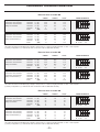
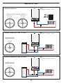
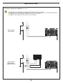
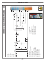
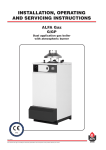
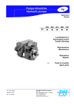
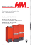
Installation, operating and
maintenance instructions
E-Tech 09 - 15
Single phase
E-Tech 22 - 28 - 36
Tri phase
excellence in hot water
09/09/2004 - 66402800
INDEX
WARNINGS
2
Who should read these instructions
Symbols
Recommendations
Applicable standards
Importants notes
Manual handling instructions
Removing the boiler from the packaging
2
2
2
2
2
2
2
INTRODUCTION
3
Description of the specifications
Lining
Heating body
Heating elements
Equipment
Connection
Dual stage thermostat
Certification
Legend
3
3
3
3
3
3
3
3
3
INSTRUCTIONS
5
User data
Setting up
Optional internal timeclock
Pressure in the heating system
5
5
5
5
TECHNICAL CHARACTERISTICS
6
Electrical data of model 09
Electrical data of model 15
Power variation (kW) relative to voltage
Electrical data of model 22 - 28 - 36
7
8
8
9
MOUNTING
10
Dimensions
Wall mounting
Installation room
10
10
10
INSTALLATION
11
Disassembling
Heating connection
Heating connection + DHW : “Y” plan
Heating connection + DHW : “S” plan
Electric connection / Models : 09 - 15
Electric connection / Models : 22 - 28 - 36
Sizing of supply wires
Wiring diagrams / Models : 09 - 15 - 22
Wiring diagrams / Model : 28
Wiring diagrams / Model: 36
Power wiring / Models : 09 - 15
Power wiring / Model : 22
Power wiring / Model : 28
Power wiring / Model : 36
11
12
12
12
13
14
14
15
16
17
18
19
20
21
HONEYWELL SUNDIAL WIRING DIAGRAMS
22
Honeywell Sundial Wiring Centre ‘S’ plan
Honeywell Sundial Wiring Centre ‘Y’ plan
22
23
COMMISSIONING AND MAINTENANCE
24
Commissioning - Water
Commissioning - Electrical
Starting the boiler
Maintenance
24
24
24
24
REMOVAL THE HEATING ELEMENTS
25
SPARE PARTS
26
-1-
WARNINGS
WHO SHOULD READ THESE INSTRUCTIONS
IMPORTANTS NOTES
These instructions should be read by:
- the specifying engineer
- the installer
- the user
- the service engineer
These instructions are an integral part of the equipment to which
they relate and must be handed to the user.
The product must be installed and serviced by qualified engineers in
accordance with the regulations in force.
The manufacturer declines all liability for any damage caused as a
result of incorrect installation or in the event of the use of appliances
or accessories that are not specified by the manufacturer.
SYMBOLS
Essential instruction for
the correct operation
of the installation.
The manufacturer reserves the right to change the
technical characteristics and specification of its
products without notice.
the availability of certain versions and their accessories
can vary following the market
Essential instruction for
the safety of persons
and the environment.
MANUAL HANDLING INSTRUCTIONS
Danger of electrocution
The weight of this boiler is 36Kg, which could
present a risk of injury.
RISK OF INJURY
LIFT WITH CARE
HEAVY
APPLIANCE
Danger of burns
Care should be taken when loading and unloading the boiler to and from vehicles.
GET HELP
RECOMMENDATIONS
We recommend that the boiler be handled by two
people until it is securely fixed to a wall.
• These instructions are an integral part of the equipment to
which they refer and the user must be provided with a copy.
• The product must be installed and serviced by qualified
engineers, in compliance with current standards.
The safest route from the vehicle to the point of
installation should be carefully assessed before
unloading the boiler.
• The manufacturer cannot accept liability for any damage
resulting from incorrect installation or from the use of
components or fittings not specified by the manufacturer.
• Any failure to follow instructions relating to tests and test
procedures may result in personal injury or risks of pollution.
It is important to switch the boiler
off before carrying out any work.
Mechanical lifting aids should be utilised
whenever possible.
REMOVING THE BOILER FROM THE PACKAGING
APPLICABLE STANDARDS
The Boilers have been manufactured to comply with
the following standards BS EN60335-2-35: 1998,
BS EN55014-2:1997 and BS EN50081-1-1: 1992.
• Before lifting the boiler from the packaging, ensure that the
installation area is clear and that there are no obstacles making
installation difficult or unsafe.
• Lay the boiler on its back (as shown on the box side), open the
box and remove the cardboard packaging.
• Remove the polythene cover and the polystyrene corner protection
pieces.
• With help from another person, lift the boiler from the packaging
holding the lipped front edges of the side panels.
• Do not lift or carry the boiler using the top automatic air vent and
bottom pump.
-2-
INTRODUCTION
DESCRIPTION OF THE SPECIFICATIONS
CERTIFICATION
This wall hung electric boiler is available in 5 models :
• models 09 and 15 are supplied with 230 Volt single phase
• models 22, 28 and 36 are only supplied with 400 V triphase + N
The boilers have been manufactured to comply with the following
standards BS EN60335-2-35: 1998, BS EN55014-2:1997 and
BS EN50081-1-1: 1992.
LEGEND
The maximum power can be adjusted for all models by acting on the
terminals bridges.
-
Model
Model
Model
Model
Model
09:
15:
22:
28:
36:
Adjustable
Adjustable
Adjustable
Adjustable
Adjustable
power
power
power
power
power
from
from
from
from
from
4.2 to 8.4 kW
7.2 to 14.4 kW
14.4 to 21.6 kW
21.6 to 28.8 kW
30 to 36 kW
1.
2.
3.
4.
5.
6.
Base for relay of DWL priority
Control circuit
Relay
Timer
Control terminals
Power terminals
LINING
The boiler is protected by a steel lining that first of all undergoes a
degreasing and phosphation process before being lacquered and
burnt at 220°C.
1
2
3
4
3
HEATING BODY
The boiler heat exchanger is constructed from mild steel with
welded joints. It is hydraulic tested under a pressure of 4.5 bar
(maximum working pressure = 3 bar).
HEATING ELEMENTS
Immersion heaters, constructed from stainless steel Incoloy 800
and mounted in the top of the boiler, provide the power source for
the Boiler.
EQUIPMENT
The boiler is equipped with all the necessary components to allow
direct connection to a heating system without the need for a feed
and expansion cistern.
These components include; primary 10 litre expansion vessel
(suitable for a system water content of up to 160 litres), pressure
and temperature gauge, safety valve, circulating pump, low water
pressure switch, control and high limit thermostats, on/off and
power level switches.
CONNECTION
The boiler is suitable for connection to most heating and hot water
systems, with a maximum working pressure of 3bar and a maximum
temperature of 85°C. It can also be used in multiple boiler installations
allowing greater outputs to be achieved.
The boiler, and connection glands for both the main power supply
and optional external controls are provided, suitable for single or
three phase electrical supply depending upon boiler output required.
An internal 3 amp MCB is linked to the incoming electrical supply to
provide the internal control circuit, from which optional controls can
be connected e.g. internal or external timeclock, room thermostat
or Honeywell Sundial controls.
DUAL STAGE THERMOSTAT
The temperature of the boiler is controlled by a dual stage thermostat
which is set by the user to give the desired boiler temperature.
When the boiler has heated up to within 7°C of the set temperature,
the thermostat switches off one power stage and therefore reduces
the heat input. Thanks to this simple but effective form of modulation,
the boiler has longer working cycles and requires less stops and
starts, thus resulting in a more even temperature across the boiler.
It also means less wear and tear on components and, importantly
it uses less power once it has reached working temperature.
-3-
5
6
INTRODUCTION
Top cover
Automatic air vent
Brass pocket
Heating elements
Heating body
Hand side panel
Cable glands
Control panel
Pressure safety valve
Expansion vessel
Rear panel
Valve of expansion vessel
Water pressure switch
Expansion vessel connection
Supplementary heating return (not used)
Circulating pump
Expansion vessel connection
Heating out
Heating return
Manual reset high limit pressure gauge
-4-
INSTRUCTIONS
USER DATA
• As with most boilers and heating appliances the casing and
pipework can get hot during normal running so the boiler must
not be covered and the surrounding area must be kept clear.
All user controls are situated on the front panel of the boiler, there
are no user controls inside the boiler casing.
The following instructions assume that the boiler has been
commissioned, and that the system is filled with water and has
been fully vented.
OPTIONAL INTERNAL TIMECLOCK
• This operates on a 24-hour sequence. Around- the outside of the
clock there are a number of white tabs - these allow 15 minute
switching times.To set a boiler cycle simply push outwards the
number of tabs required for your heating period.
SETTING UP
• Before switching on any electrical supplies to the boiler ensure
that the combined temperature and pressure gauge reads at
least 1 bar and the control thermostat is set to the desired
temperature.
• If an internal time clock is fitted ensure that this is switched on
(see “Optional Internal Time Clock”) and if any other auxiliary
controls are fitted e.g. programmer, room thermostats, cylinder
thermostats etc, consult appropriate manufacturers' instructions
to switch these on.
• Switch on any local means of isolation to boiler.
Remember : tab OUT = BOILER ON
tab IN = BOILER OFF
The time of day is marked by an arrow on the inner part of the clock
- set the outer time to coincide with this arrow.
On the centre part of the clock there is a switch.
This has three positions :
• Switch down - timeclock off
• Switch middle - timeclock timed (normal position)
• Switch up - timeclock on constant.
• Switch the boiler on using the ON/OFF switch (the neon light on
the switch should now glow).
PRESSURE IN THE HEATING SYSTEM
• Turn on both power level switches - after a short period of time
the boiler temperature should start to rise, indicated by the
combined temperature and pressure gauge. If the boiler fails to
operate, the overheat safety thermostat should be checked.
Access to the thermostat reset button is obtained by unscrewing
(anti-clockwise) the domed button cover on the front panel
(a screwdriver is not required).The reset button can then be
seen - press the button, a click should be heard and the button
is reset. If no click was heard the device is not at fault and
further investigation is required by a suitably qualified engineer.
• The internal clock or external programmer can now be set to
allow on/off periods as desired. The ON/OFF switch and 2 power
level switches should be left in the ON position during normal use.
The CH pressure must be a minimum of 1 bar and must be checked
by the end user on a regular basis. If the pressure drops under 0.5
bar, the integrated water pressure switch blocks the appliance until
the pressure in the system returns to a level above 0.8 bar.
The installer fits the system with a separate fill valve underneath the
appliance. Make sure that the appliance is powered off when filling
the system. To do this, turn the on/off switch.
For more information, please ask your installer when the system is
delivered.
A safety valve is provided underneath the appliance. If the system
pressure exceeds 3 bars, this valve opens and drains the water
from the system. In this case, please contact your installer.
the power level switches will automatically switch on and
off during normal boiler operation, depending on boiler
temperature.
• If the boiler is not in regular daily use during cold periods, it is
recommended that it be fitted with a frost sensing thermostat to
override the timeclock and prevent the system from freezing.
LEGEND
1. ON/OFF switch
2. Power levels switch
3. Optional internal
clock or controler
4. Combined temperature
and pressure gauge
5. Boiler shutdown
indicator light
6. Manual reset high
limit thermostat
1
2
3
4
-5-
5
6
7
7. Control thermostat :
1 = 40°C
2 = 50°C
3 = 60°C
4 = 70°C
5 = 80°C
TECHNICAL CHARACTERISTICS
Model
09
15
22
28
36
Power
4.2 to
8.4 kW
7.2 to
14.4 kW
14.4 to
21.6 kW
21.6 to
28.8 kW
30 to
36 kW
Nominal supply voltage
1 x 230 V
1 x 230 V
3 x 400 V + N
3 x 400 V + N
3 x 400 V + N
Ohmic esistance
of element
37.8 Ohm
22 Ohm
22 Ohm
22 Ohm
26.45 Ohm
Heating element type
2 x 1.4 kW
2 x 2.4 kW
2 x 2.4 kW
2 x 2.4 kW
3 x 2 kW
Number of elements
3
3
5
6
6
Water capacity
(Litres)
13
13
13
13
13
Expansion vessel capacity
(Litres)
10
10
10
10
10
Max. working pressure
(bars)
3
3
3
3
3
Min. working pressure
(bars)
0.8
0.8
0.8
0.8
0.8
Max. working temperature
(°C)
85
85
85
85
85
Hydraulic presure drop
(mbar)
10
20
45
85
125
Heating connection
3/4”
3/4”
3/4”
3/4”
3/4”
Height (mm)
763
763
763
763
763
Width (mm)
442
442
442
442
442
Depth (mm)
332
332
332
332
332
Weight empty (kg)
45
45
45
45
45
-6-
TECHNICAL CHARACTERISTICS
Electrical data of model 09
Single phase 8.4 kW (*)
Terminals 1 and 2 shunted
Terminals 3, 4, 5 and 6 shunted
Relay K3 activated
Terminal 3
Terminal 1
Power
L1 (A)
N (A)
(kW)
STAGE 1
STAGE 2
TOTAL
24
24
5.6
12
12
2.8
36
36
8.4
POWER TERMINALS
1
2
N
Single phase 7 kW
Terminals 1 and 2 shunted
Terminals 3, 4 and 5 shunted
Relay K3 activated
Single phase 5.6 kW
Terminals 1 and 2 shunted
Terminals 3, 4, 5 and 6 shunted
Relay K3 disactivated (**)
Single phase 4.2 kW
Terminals 1 and 2 shunted
Terminals 3, 4 and 5 shunted
Relay K3 disactivated (**)
Terminal 3
Terminal 1
Power
Terminal 3
Terminal 1
Power
Terminal 3
Terminal 1
Power
L1 (A)
N (A)
(kW)
L1 (A)
N (A)
(kW)
L1 (A)
N (A)
(kW)
24
24
5.6
6
6
1.4
12
12
2.8
12
12
2.8
12
12
2.8
6
6
1.4
4
5
6
L
30
30
7
1
N
2
3
L
4
5
6
1
N
2
3
L
4
5
6
1
N
2
3
L
4
5
6
24
24
5.6
31.2
31.2
4.2
This values are based on standard supply voltage in Europe, that is 1 x 230V for single phase and 3 x 400V + N for tri phase.
(*) Factory configuration / (**) Remove the shunt 17 and 18 in order to desactivate the relay.
-7-
3
TECHNICAL CHARACTERISTICS
Electrical data of model 15
Single phase 14.4 kW (*)
Terminals 1 and 2 shunted
Terminals 3, 4, 5 and 6 shunted
Relay K3 activated
Terminal 3
Terminal 1
Power
STAGE 1
STAGE 2
TOTAL
41.6
41.6
9.6
20.8
20.8
4.8
62.4
62.4
14.4
L1 (A)
N (A)
(kW)
POWER TERMINALS
1
2
N
Single phase 12 kW
Terminals 1 and 2 shunted
Terminals 3, 4 and 5 shunted
Relay K3 activated
Single phase 9.6 kW
Terminals 1 and 2 shunted
Terminals 3, 4, 5 and 6 shunted
Relay K3 disactivated (**)
Single phase 7.2 kW
Terminals 1 and 2 shunted
Terminals 3, 4 and 5 shunted
Relay K3 disactivated (**)
Terminal 3
Terminal 1
Power
Terminal 3
Terminal 1
Power
Terminal 3
Terminal 1
Power
L1 (A)
N (A)
(kW)
L1 (A)
N (A)
(kW)
L1 (A)
N (A)
(kW)
41.6
41.6
9.6
10.4
10.4
2.4
20.8
20.8
4.8
20.8
20.8
4.8
20.8
20.8
4.8
10.4
10.4
2.4
3
4
5
6
L
52
52
12
1
N
2
3
L
4
5
6
1
N
2
3
L
4
5
6
1
N
2
3
L
4
5
6
41.6
41.6
9.6
31.2
31.2
7.2
This values are based on standard supply voltage in Europe, that is 1 x 230V for single phase and 3 x 400V + N for tri phase.
(*) Factory configuration / (**) Remove the shunt 17 and 18 in order to desactivate the relay.
Power variation (kW) relative to voltage
220 V
230 V
240 V
3 x 380 V
3 x 400 V
3 x 415 V
E-Tech W 09
7.7
8.4
9.1
E-Tech W 15
13.2
14.4
15.7
E-Tech W 22
19.5
21.6
23.3
E-Tech W 28
26.0
28.8
31.0
E-Tech W 36
32.5
36.0
38.8
-8-
TECHNICAL CHARACTERISTICS
Electrical data of model 22
Tri phase 21.6 kW (*)
Terminals 3 and 4 shunted
Terminals 5 and 6 shunted
Relay K43 activated
Tri phase 14.4 kW
Terminals 3 and 4 shunted
Terminals 5 and 6 shunted
Relay K3 disactivated (**)
Terminal
Terminal
Terminal
Terminal
Power
2
3
5
1
Terminal
Terminal
Terminal
Terminal
Power
2
3
5
1
L1
L2
L3
N
L1
L2
L3
N
STAGE 1
STAGE 2
TOTAL
POWER TERMINALS
(A)
(A)
(A)
(A)
(kW)
20.8
20.8
20.8
0
14.4
10.4
10.4
10.4
0
7.2
31.2
31.2
31.2
0
21.6
N L1 L2
(A)
(A)
(A)
(A)
(kW)
10.4
10.4
10.4
0
7.2
10.4
10.4
10.4
0
7.2
20.8
20.8
20.8
0
14.4
1 2 3
N L1 L2
1
2
3
4
5
6
L3
4
5
L3
6
This values are based on standard supply voltage in Europe, that is 1 x 230V for single phase and 3 x 400V + N for tri phase.
(*) Factory configuration / (**) Remove the shunt 17 and 18 in order to desactivate the relay.
Electrical data of model 28
Tri phase 28.8 kW (*)
Terminals 3 and 4 shunted
Terminals 5 and 6 shunted
Relay K4 activated
Tri phase 21.6 kW
Terminals 3 and 4 shunted
Terminals 5 and 6 shunted
Relay K4 disactivated (**)
STAGE 1
STAGE 2
TOTAL
POWER TERMINALS
Terminal
Terminal
Terminal
Terminal
Power
2
3
5
1
L1
L2
L3
N
(A)
(A)
(A)
(A)
(kW)
20.8
20.8
20.8
0
14.4
20.8
20.8
20.8
0
14.4
41.6
41.6
41.6
0
28.8
1 2 3
N L1 L2
4
5
L3
6
Terminal
Terminal
Terminal
Terminal
Power
2
3
5
1
L1
L2
L3
N
(A)
(A)
(A)
(A)
(kW)
20.8
20.8
20.8
0
14.4
10.4
10.4
10.4
0
7.2
31.2
31.2
31.2
0
21.6
1 2 3
N L1 L2
4
5
L3
6
This values are based on standard supply voltage in Europe, that is 1 x 230V for single phase and 3 x 400V + N for tri phase.
(*) Factory configuration / (**) Remove the shunt 19 and 20 in order to desactivate the relay.
Electrical data of model 36
Tri phase 36 kW (*)
Terminals 3 and 4 shunted
Terminals 5 and 6 shunted
Relay K4 activated
Tri phase 30 kW
Terminals 3 and 4 shunted
Terminals 5 and 6 shunted
Relay K4 disactivated (**)
STAGE 1
STAGE 2
TOTAL
POWER TERMINALS
Terminal
Terminal
Terminal
Terminal
Power
2
3
5
1
L1
L2
L3
N
(A)
(A)
(A)
(A)
(kW)
26
26
26
0
18
26
26
26
0
18
52
52
52
0
36
1 2 3
N L1 L2
4
5
L3
6
Terminal
Terminal
Terminal
Terminal
Power
2
3
5
1
L1
L2
L3
N
(A)
(A)
(A)
(A)
(kW)
26
26
26
0
18
17
17
17
0
12
43
43
43
0
30
1 2 3
N L1 L2
4
5
L3
6
This values are based on standard supply voltage in Europe, that is 1 x 230V for single phase and 3 x 400V + N for tri phase.
(*) Factory configuration / (**) Remove the shunt 19 and 20 in order to desactivate the relay.
-9-
MOUNTING
332 mm
763 mm
763 mm
442 mm
DIMENSIONS
178 mm
90 mm
379 mm
WALL MOUNTING
INSTALLATION ROOM
The appliance must be positioned in such a way as to be easily accessible
at all times. In addition, the following minimum distances around the
appliance must be complied with
53,2 mm
48,4 mm
101,6 mm
101,6 mm
48,4 mm
53,2 mm
Min.
25 mm
• The boiler must be fixed to a non flammable wall.
• Observing the clearances shown below, drill 2 off
14mm x 100mm holes.
• Fit the 2 bolts supplied and hang the wall bracket.
• Fit washers and nuts
• Hang the boiler
Min.
400 mm
FROST PROTECTION
The boiler is NOT fitted with frost protection. If the
boiler is being installed in a position where freezing
could take place, then a suitable external frost
thermostat should be fitted.
CONNECTING TO THE SYSTEM
The boiler is designed to operate on a sealed system
(ie. no open vent or feed and expansion cistern). Hot
water expansion within the system is taken up by the
internal 10 litre expansion vessel.This is suitable for
systems up to 160 litres capacity. If the system
capacity is more than this then an additional expansion
vessel may be required.This can be fitted external to
the boiler at a convenient place on the pipework.
Please note that the circulation pump is fitted to the
flow connection.
Min.
200 mm
- 10 -
INSTALLATION
DISASSEMBLING
1
A
Panel removal and access to hydraulic connections
1. undo screws
2. tilt panel towards you and lift clear remove the top cover
3. loosen screws of the control panel
4. turn up the control panel
5. block the control panel with the screw
2
2
B
3
C
4
5
- 11 -
INSTALLATION
NOTE:
• controller not supplied in standard
HEATING CONNECTION
4
36
39
1 2
3
4
5
6
6
31 32
29
11 12
26
25
16
18
17
16
4
19
21 22
26
41
5
41
5
25
13
1
13
1
28
27
31 32
8 9
11 12
28
27
8 9
29
7
7
33
3
5
33
3
38
37
43
5
1 2
3
43
5
39
15
38
37
11 12 13 14
36
Floor heating
30 - 50°C
15
Factory setting
30 - 85°C
11 12 13 14
Limiting the maximum adjustable temperature
23
2
18
17
4
19
21 22
23
2
HEATING CONNECTION + DHW : “Y” PLAN
NOTE:
• controller not supplied in standard
Limiting the minimum
adjustable temperature
60 - 85°C
38
37
39
1 2
3
4
31 32
11 12
5
25
41
26
13
1
28
27
8 9
29
7
33
3
6
43
5
5
36
16
18
17
4
19
21 22
23
2
HEATING CONNECTION + DHW : “S” PLAN
NOTE:
• controller not supplied in standard
Limiting the minimum
adjustable temperature
60 - 85°C
38
37
39
1 2
3
4
31 32
11 12
M
5
25
13
14
1
28
27
26
8 9
29
7
33
3
6
43
5
5
36
16
- 12 -
M
18
17
4
19
21 22
23
2
INSTALLATION
ELECTRIC CONNECTION / MODELS : 09 - 15
•
•
•
•
This appliance must be permanently connected to fixed wiring and must be earthed.
The wiring must be carried out by a competent person and be in accordance with the current IEE Wiring Regulations.
Isolation device must be provided with a minimum contact clearance of 3mm.
The MCB must be readily accessible and adjacent to the appliance.
L1
N
N
L1
Power supply
230 V mono
1
L1
N
1
2
3
4
5
6
7
8
1
2
3
4
5
6
7
8
2
N
Power supply
230 V mono +
Safety contactor
1
- 13 -
3
4
5
6
4
5
6
L1
2
3
INSTALLATION
ELECTRIC CONNECTION / MODELS : 22 - 28 - 36
•
•
•
•
This appliance must be permanently connected to fixed wiring and must be earthed.
The wiring must be carried out by a competent person and be in accordance with the current IEE Wiring Regulations.
Isolation device must be provided with a minimum contact clearance of 3mm.
The MCB must be readily accessible and adjacent to the appliance.
L3 L2 L1
N
N L1 L2
L3
Power supply
3 x 400 V + Neutral
1
L3 L2 L1
N
1
2
3
4
5
6
7
8
1
2
3
4
5
6
7
8
2
3
4
N L1 L2
Power supply
3 x 400 V + Neutral +
Safety contactor
1
2
3
5
6
L3
4
5
6
SIZING OF SUPPLY WIRES
the supply wires are sized depending of the type and current of the MCB, this last is firstly sized depending of the nominal current of the boiler.
The admissible current of the supply wires depends of the ambient temperature, the section and the length of the wires, the wires insulation,
the wires canalisation, the mounting type and the environment.
The following values are given for information for an ambient temperature of 30°C and a maximal length of 5 meters. In all the cases, the
installation must be in accordance with the current IEE Wiring Regulations.
Nominal section
(mm2)
Nominal current of the MCB
(A)
1.5
2.5
4
6
10
16
16
25
32
40
63
80
- 14 -
- 15 -
A
B
C
D
E
F
G
H
I
J
K1
K2
K3
L
N
L1
b
bk
br
g
or
pk
r
v
w
y
b
3
1
b
br
4
2
b
br
3 amp
MCB
b
br
A
b
E
bk
b
bk
b
6
5
bk
C
2
t 1
B
ON/OFF switch
Manual reset high limit thermostat
Water pressure switch
Alarm indicator
Switch indicator
Optional room thermostat
Cirluating pump
Boiler thermostat 60 - 85°C
Boiler thermostat 53 - 78°C
Power level switch
Power relay 1 - level 1
Power relay 1 - level 2
Power relay 2 - level 1
Timer
or
Blue
Black
Brown
Grey
Orange
Pink
Red
Violet
White
Yellow
g
r
b
r
C
D
p
C
b
2
1
or
b
or
8
7
10
b
y
b
9
11
b
y
12
or
13
1-2:
3-4:
5-6:
7-8:
10-11:
12-13:
14-15:
17-18:
or
t
F
2.1.
g
2.1.
g
I
t
or
2.2.
pk
2.2.
L
J
Life (230V ~ 50Hz)
Neutral
Time clock (optional)
Master Relay (optional)
Stop Bridge
Room thermostat (optional)
Boiler pump
Relay K3 disactivated
g
H
r
g
w
J
r
17
w
14
18
G
pk
w
r
M
b
b
b
16
15
b
K2
K3
K1
WIRING DIAGRAMS / MODELS : 09 - 15 - 22
INSTALLATION
- 16 -
A
B
C
D
E
F
G
H
I
J
K1
K2
K3
K4
L
N
L1
b
bk
br
g
or
pk
r
v
w
y
b
3
1
b
br
4
2
b
br
3 amp
MCB
b
br
A
b
E
bk
b
bk
b
6
5
bk
C
2
t 1
B
ON/OFF switch
Manual reset high limit thermostat
Water pressure switch
Alarm indicator
Switch indicator
Optional room thermostat
Cirluating pump
Boiler thermostat 60 - 85°C
Boiler thermostat 53 - 78°C
Power level switch
Power relay 1 - level 1
Power relay 1 - level 2
Power relay 2 - level 1
Power relay 2 - level 2
Timer
or
Blue
Black
Brown
Grey
Orange
Pink
Red
Violet
White
Yellow
r
g
b
r
C
D
p
C
b
2
1
or
b
or
8
7
10
b
y
b
9
11
b
y
12
or
13
1-2:
3-4:
5-6:
7-8:
10-11:
12-13:
14-15:
17-18:
19-20:
or
t
F
2.1.
g
2.1.
g
t
I
or
2.2.
pk
2.2.
L
J
Life (230V ~ 50Hz)
Neutral
Time clock (optional)
Master Relay (optional)
Stop Bridge
Room thermostat (optional)
Boiler pump
Relay K3 disactivated
Relay K4 disactivated
g
H
r
g
w
J
pk
pk
r
19
17
w
w
14
20
18
G
w
pk
w
r
M
b
b
b
b
16
15
b
K4
K2
K3
K1
WIRING DIAGRAMS / MODEL : 28
INSTALLATION
- 17 -
A
B
C
D
E
F
G
H
I
J
K1
K2
K3
K4
K5
K6
L
N
L1
b
bk
br
g
or
pk
r
v
w
y
b
3
1
b
br
4
2
b
br
3 amp
MCB
b
br
A
b
E
bk
b
bk
b
6
5
bk
C
2
t 1
B
ON/OFF switch
Manual reset high limit thermostat
Water pressure switch
Alarm indicator
Switch indicator
Optional room thermostat
Cirluating pump
Boiler thermostat 60 - 85°C
Boiler thermostat 53 - 78°C
Power level switch
Power relay 1 - level 1
Power relay 1 - level 2
Power relay 2 - level 1
Power relay 2 - level 2
Power relay 3 - level 1
Power relay 3 - level 2
Timer
or
Blue
Black
Brown
Grey
Orange
Pink
Red
Violet
White
Yellow
r
g
b
r
C
D
p
C
b
2
1
or
b
or
8
7
10
b
y
b
9
11
b
y
12
or
13
1-2:
3-4:
5-6:
7-8:
10-11:
12-13:
14-15:
17-18:
19-20:
21-22:
23-24:
or
t
F
2.1.
g
2.1.
g
t
I
or
2.2.
pk
2.2.
L
J
Life (230V ~ 50Hz)
Neutral
Time clock (optional)
Master Relay (optional)
Stop Bridge
Room thermostat (optional)
Boiler pump
Relay K3 disactivated
Relay K4 disactivated
Relay K5 disactivated
Relay K6 disactivated
g
H
r
g
w
J
pk
pk
pk
r
r
23
19
21
17
w
w
w
w
14
24
20
22
18
G
w
w
pk
w
w
r
M
b
b
b
b
b
b
16
15
b
K6
K4
K2
K5
K3
K1
WIRING DIAGRAMS / MODEL : 36
INSTALLATION
K1
b
b
bk
bk
2 x bk
K2
b
b
r
r
b
b
or
or
r
r
b
b
or
or
2 x or
3xb
3xb
b
b
bk
bk
b
b
r
r
K3
2
4
5
17 18
17 18
- 18 5
6
1
N
3
L
4
5
2
L
3
4
5
12 kW
17 18
4
2
17 18
L
1
N
6
6
N
1
1
N
2
3
L
4
5
2
L
3
4
5
9.6 kW
17 18
3
6
5.6 kW
17 18
2
14.4 kW
3
L
7 kW
6
6
N
1
1
N
2
4
5
2
L
3
4
5
7.2 kW
3
L
4.2 kW
17 18
N
1
1
N
8.4 kW
17 18
MONO
PHASE
Type 15
MONO
PHASE
Type 9
6
6
POWER WIRING / MODELS : 09-15
INSTALLATION
17 18
17 18
17 18
17 18
17 18
17 18
17 18
17 18
K1
K2
1 x bk
or
Or
3xb
- 19 -
b
b
2 x bk
K3
TRI
PHASE
Type 22
1 2 3
N L1 L2
4
5
L3
21.6 kW
6
1 2 3
N L1 L2
4
5
L3
14.4 kW
6
POWER WIRING / MODEL : 22
INSTALLATION
17 18
17 18
17 18
17 18
b
b
r
r
bk
bk
1xr
or
or
2xr
r
r
3 x or
bk
Bk
or
or
bk
bk
r
r
b
b
or
Or
4xb
- 20 -
b
b
3 x bk
K1
K2
1 x bk
K3
b
r
bk
or
b
b
r
r
bk
bk
1xr
or
or
3xr
r
r
4 x or
bk
Bk
b
r
bk
or
or
or
bk
bk
r
r
b
b
K4
TRI
PHASE
Type 28
1 2 3
N L1 L2
4
5
L3
28.8 kW
6
1 2 3
N L1 L2
4
5
L3
21.6 kW
6
POWER WIRING / MODEL : 28
INSTALLATION
19 20
19 20
19 20
19 20
- 21 b
b
r
r
bk
bk
or
or
K1
6xb
r
r
bk
Bk
or
Or
6 x or
5 x bk
b
b
K2
1 x bk
5xr
1xr
r
r
bk
bk
or
or
b
b
K3
r
r
bk
bk
or
or
b
b
K4
TRI
PHASE
Type 36
b
b
r
r
bk
bk
or
or
K5
1 2 3
N L1 L2
4
5
L3
36 kW
6
1 2 3
N L1 L2
r
r
bk
bk
or
or
4
5
L3
K6
30 kW
b
b
6
POWER WIRING / MODEL : 36
19 20
19 20
19 20
19 20
INSTALLATION
HONEYWELL SUNDIAL WIRING DIAGRAMS
gr
gr
b
b
MOTOR
MOTOR
br
br
o
o
Honeywell
Sundial Wiring Centre
`S ` Plan
V4043H
HTG ZONE VALVE
b
T6306B
ROOM STAT
1
CYLINDER
STAT
3
gr
C
o
o
br
b
b
Note: Earth wires not shown for clarity
During installation the earth wires from each
component connect to terminal 3 in the wiring centre
br
gr
2
V4043H
DHW ZONE VALVE
1
2
3
4
5
6
7
8
9
10
E
CABLE COLOUR CODES
HW
bk- black
br- brown
r-red
w-white
y- yellow
o - orange
b - blue
v - violet
p - pink
gr - grey
HTG
N
L
Note: All bold numbers indicate a DIN rail terminal connection
g
3 amp
MCB
L1
or
1
br
2
br
A
br
B
bk
2
bk
C
r
t
F
1
or
C
1
10
2
y
11
y
12
or
13
g
t
p
bk
g
H
2.1.
r
r
or
r
L
g
pk
2.1.
I
6
8
b
b
3
b
4
b
b
b
9
b
b
b
b
b
b
Note: Illustrated model = 36 kW Tri Phase
- 22 -
b
21
w
18
w
b
22
w
w
b
J
w
pk
pk
b
2.2.
t
b
N
17
7
D
r
2.2.
5
r
16
J
or
or
E
15
M
G
g
C
14
pk
pk
19
23
w
w
20
w
b
24
w
b
b
HONEYWELL SUNDIAL WIRING DIAGRAMS
b
V4073A
MID POSITION
ZONE VALVE
w
T6306B
ROOM STAT
1
C
2
6
7
1
w
b
o
Note: Earth wires not shown for clarity
During installation the earth wires from each
component connect to terminal 3 in the wiring centre
CYLINDER
STAT
3
1
2
gr
b
Honeywell
Sundial Wiring Centre
`Y ` Plan
2
3
4
5
8
9
10
HW ON
HW OFF
E
HTG
CABLE COLOUR CODES
bk- black
br- brown
r-red
w-white
y- yellow
o - orange
b - blue
v - violet
p - pink
gr - grey
N L
Note: All bold numbers indicate a DIN rail terminal connection
g
3 amp
MCB
L1
or
1
br
2
br
A
br
B
bk
2
bk
C
r
t
F
1
or
C
1
10
2
y
11
y
12
or
13
g
t
p
bk
g
H
r
r
or
r
L
g
pk
2.1.
I
6
8
b
b
3
b
4
b
b
b
9
b
b
b
b
b
b
Note: Illustrated model = 36 kW Tri Phase
- 23 -
b
21
w
18
w
b
22
w
w
b
J
w
pk
pk
b
2.2.
t
b
N
17
7
D
r
2.2.
or
r
16
J
or
2.1.
5
E
15
M
G
g
C
14
pk
pk
19
23
w
w
20
w
b
24
w
b
b
COMMISSIONING AND MAINTENANCE
COMMISSIONING - WATER
STARTING THE BOILER
1. The system must be thoroughly cleansed prior to connection
of the boiler. The system water should be treated to prevent
general corrosion and deposition of scale or sludge in the
boiler, please refer to BS7593. If installing the boiler onto an
existing system, ACV recommend that an approved system
cleaner is used.
1.
2.
3.
4.
5.
2. Fill and pressurise the boiler and system to 1.5 bar, making
sure to vent the boiler via the automatic air vent on top of the
boiler. Note that the black dust cap on the air vent should be
left loose to allow the auto vent to function.
3. Check for leaks.
For specialist advice on water treatment products, contact:
Fernox, Britannia Works
Clavering, Essex CB11 4QZ
Tel 01799 550811
Switch on the internal or external timeclock (if fitted)
Switch on internal MCB
Switch on local isolator to boiler
Turn the boiler on using the ON/OFF switch
Switch on the power levels switch stage 1, the first stage
contactors will energise
6. Switch on the power levels switch stage 2, after a short delay
the second stage contactors will energise. Note: the power
stage delay timer settings should be verified as shown in item
4 under "Commissioning - Electrical"
7. The boiler temperature will now rise as indicated by the combined
temperature and pressure gauge
8. The temperature will continue to rise until the control thermostat
temperature setting is reached then the boiler will switch off.
Once these procedures have been followed the system can be left
to operate normally by the following method.
COMMISSIONING - ELECTRICAL
The Electrical installation supplying this boiler must conform to the
current IEE Regulations.
1. Remove the front panel and check all electrical connections for
tightness.
2. Ensure all internal relays, contactors etc are secure on the DIN
rails.
3. Set all panel control switches to off.
4. Check the power stage delay timer settings - Adjuster (A) is
factory set to the 1 to 10 minute position which is the optimum
setting for the boiler and should be verified during commissioning.
- Adjuster (B) is used to set the DELAY ON time of the following
stage contactors, the available settings are in 1 minute
increments if A is set to 1 to 10 minutes.
This function is particularly useful in areas where gradual
switching of electrical load is required and the resulting
maximum demand kept to a minimum.The timers add to the
flexibility of the installation but must be optimised by a qualified
engineer.The normal setting is 1.
5. Set internal MCB to off position.
6. Set the control thermostat to desired temperature.
A
1.
2.
3.
4.
5.
Ensure that boiler thermostat is set to the desired temperature
Turn the boiler on using the ON/OFF switch
Turn on power level switch 1
Turn on power level switch 2
Set timeclock (if fitted) and/or external controls to desired boiler
operating on/off times.
After one week of operation all electrical
connections should be re-checked for tightness and
the boiler water system checked for leaks and air
and rectified if necessary.
MAINTENANCE
For safety reasons it is recommended that the boiler is serviced
annually and that servicing is carried out by a qualified service
engineer.
Before carrying out any work on the system ensure that
the boiler is cool and all electrical supplies are isolated.
1. After removing front cover undo the four screws retaining the
front control panel and gently let the panel suspend on the
wiring to the rear of the panel. Undertake a visual inspection of
the boiler looking out for signs of water leakage from joints,
expansion vessel, and the area around the elements on top of
the boiler.
2. Undertake a visual inspection of all cabling in the boiler casing
checking for signs of overheating or burning.
3. Check all push-on electrical connectors for tightness and good
connection to the relative components.
4. Using a correct fitting screwdriver check all electrical terminals
on DIN rails and on all components for tightness.
5. Check the settings on the internal timers in accordance with
the "Commissioning - Electrical" section.
6. Replace the control panel and the boiler front cover and refit
screws.
7. Reinstate the electrical supply and follow the procedures set
out in the commissioning section.
B
- 24 -
REMOVAL THE HEATING ELEMENTS
1
3
2
- 25 -
SPARE PARTS
N° Casing
09
15
22
28
36
A01 Side panel
21471421
21471421
21471421
21471421
21471421
A02 Front panel
21473421
21473421
21473421
21473421
21473421
A03 Top cover
21475421
21475421
21475421
21475421
21475421
A04 Rear panel
21474421
21474421
21474421
21474421
21474421
A05 Control panel ABS
497B1025
497B1025
497B1025
497B1025
497B1025
A06 Wall mounting
21480069
21480069
21480069
21480069
21480069
A07 Body heating
30537482
30537482
30537482
30537482
30537482
A08 Control panel
21477421
21477421
21477421
21477421
21477421
A09
21479421
21479421
21479421
21479421
21479421
Electric support
A03
A01
A06
A04
A07
A02
A09
A01
A05
A08
- 26 -
SPARE PARTS
N°
09
15
22
28
36
B01 Base for relay
Accessories
54428195
54428195
54428195
54428195
54428195
B02 Control circuit “Siemens”
54766015
54766015
54766015
54766015
54766015
B03 Relay Siemens 3TG
54452082
54452082
54452082
54452082
54452082
B04 Timer “Crouset”
54428192
54428192
54428192
54428192
54428192
B05 Blocking
54452092
54452092
54452092
54452092
54452092
54767014
54767014
54767014
54767014
54767014
B06 Terminal WKN 16/U blue
B07 Terminal 16 mm WKN 16/U
54428179
54428179
54428179
54428179
54428179
B08 Terminal end APN 16 mm2
54428091
54428091
54428091
54428091
54428091
2
B09 Terminal WKN10 sl/u
54428155
54428155
54428155
54428155
54428155
B10 Shunt IVBWKN 16-2
54428278
54428278
54428278
54428278
54428278
B11 Control terminal block
54767015
54767015
54767015
54767015
54767015
B12 Green switch
54766016
54766016
54766016
54766016
54766016
B13 Yellow switch
54766017
54766017
54766017
54766017
54766017
B14 Combined T° and pressure gauge Ø 40mm
54763012
54763012
54763012
54763012
54763012
B15 Red alarm indicator Ø 10mm / 240V
54766001
54766001
54766001
54766001
54766001
B16 Control thermostat 2 Stages
54764017
54764017
54764017
54764017
54764017
B17 Button thermostat
54764021
54764021
54764021
54764021
54764021
B18 Manual reset high limit thermostat 103°C
54764009
54764009
54764009
54764009
54764009
B19 Cable gland (PG29)
54428113
54428113
54428113
54428113
54428113
B20 Brass pocket
63438003
63438003
63438003
63438003
63438003
B21 Heating element 2 x 1.4 kW
54428183
-
-
-
-
B22 Heating element 2 x 2.4 kW
-
54428182
54428182
54428182
-
B23 Heating element 3 x 2 kW
-
-
-
-
54428204
B24 Water pressure switch
557D3011
557D3011
557D3011
557D3011
557D3011
B25 Circulating pump
557A4009
557A4009
557A4009
557A4009
557A4009
B26 Pressure safety valve 3 bars Ø 1/2”
55426017
55426017
55426017
55426017
55426017
B27 Automatic air vent
55445007
55445007
55445007
55445007
55445007
B29 Expansion vessel 10 Litres
557A7006
557A7006
557A7006
557A7006
557A7006
B30 Complete control panel
24614142
24614142
24614143
24614144
24614145
B28 Flexible tube
- 27 -
SPARE PARTS
B01
B02
B03
B04
B05
B06
B07
B08
B09
B10
B11
B12
B13
B14
B15
B16
B17
B18
B19
B20
B21
B22
B23
B24
B25
B26
B27
B28
B30
B29
-
-
-
-
-
-
- 28 -
- 29 -
www.acv-world.com
excellence in hot water
INTERNATIONAL
FRANCE
SLOVAK REPUBLIC
ACV international n.v
KERKPLEIN, 39
B-1601 RUISBROEK - BELGIUM
TEL.: +32 2 334 82 20
FAX: +32 2 378 16 49
E-MAIL: [email protected]
ACV FRANCE sa
31, RUE AMPERE - Z.I MI - PLAINE
F-69680 CHASSIEU - FRANCE
TEL.:+33 4 72 47 07 76
FAX:+33 4 72 47 08 72
E-MAIL: [email protected]
ACV SLOVAKIA s.r.o.
PLUHOVÁ 49
831 04 BRATISLAVA - SLOVAK REPUBLIC
TEL.:+421 2 444 62 276
FAX:+421 2 444 62 275
E-MAIL: [email protected]
BELGIUM
ITALIA
SLOVENIA
ACV BELGIUM nv/sa
KERKPLEIN, 39
B-1601 RUISBROEK-BELGIUM
TEL.: +32 2 334 82 40
FAX: +32 2 334 82 59
E-MAIL: [email protected]
ACV ITALIA
VIA PANA 92
I-48018 FAENZA (RA) - ITALIA
TEL.:+39 0546 64 61 44
FAX:+39 0546 64 61 50
E-MAIL: [email protected]
ACV D.O.O. SLOVENIA
OPEKARNA 22b
1420 TRBOVLJE - SLOVENIA
TEL.:+386 356 32 830
FAX:+ 386 356 32 831
E-MAIL: [email protected]
CHILE
NEDERLAND
UK
ALBIN TROTTER Y ACV LTDA
SAN PABLO 3800
QUINTA NORMAL - SANTIAGO - CHILE
TEL.:+56 2 772 01 69
FAX:+56 2 772 92 62/63
E-MAIL: [email protected]
ACV NEDERLAND bv
POSTBUS 350
NL-2980 AJ RIDDERKERK - NEDERLAND
TEL.:+31 180 42 10 55
FAX:+31 180 41 58 02
E-MAIL: [email protected]
ACV UK Ltd
ST. DAVID’S BUSINESS PARK
DALGETY BAY - FIFE - KY11 9PF
TEL.:+44 1383 82 01 00
FAX:+44 1383 82 01 80
E-MAIL: [email protected]
CZECH REPUBLIC
POLAND
USA
ACV CR SPOL. s.r.o
NA KRECKU 365
CR-109 04 PRAHA 10 - CZECH REPUBLIC
TEL.:+420 2 720 83 341
FAX:+420 2 720 83 343
E-MAIL: [email protected]
ACV POLSKA sp. z.o.o.
UL.WITOSA 3
87 - 800 WLOCLAWEK - POLAND
TEL.:+48 54 412 56 00
FAX:+48 54 412 56 01
E-MAIL: [email protected]
TRIANGLE TUBE PHASE III
FREEWAY CENTER - 1 TRIANGLE LANE
BLACKWOOD NJ 08012 - USA
TEL.:+1 856 228 8881
FAX:+1 856 228 3584
E-MAIL: [email protected]
DEUTSCHLAND
PORTUGAL
ACV WÄRMETECHNIK GMBH & CO KG
GEWERBEGEBIET GARTENSTRASSE
D-08132 MÜLSEN OT ST. JACOB - DEUTSCHLAND
TEL.:+49 37601 311 30
FAX:+49 37601 311 31
E-MAIL: [email protected]
BOILERNOX LDA
RUA OUTEIRO DO POMAR
CASAL DO CEGO, FRACÇÃO C,
PAVILHÃO 3 - MARRAZES
2400-402 LEIRIA - PORTUGAL
TEL.:+351 244 837 239/40
FAX:+351 244 823 758
E-MAIL: [email protected]
ESPAÑA
ACV ESPAÑA
C/DE LA TEIXIDORA, 76
POL. IND. LES HORTES
E-08302 MATARÓ - ESPANA
TEL.:+34 93 759 54 51
FAX:+34 93 759 34 98
E-MAIL: [email protected]
RUSSIA
ACV RUSSIA
1/9, MALYI KISELNYI
103031 MOSCOW - RUSSIA
TEL.:+7 095 928 48 02 / +7 095 921 89 79
FAX:+7 095 928 08 77
E-MAIL: [email protected]
ARGENTINA
DENMARK
NEW ZEALAND
TECNOPRACTICA
ALFEREZ BOUCHARD 4857
1605 CARAPACHAY - BUENOS AIRES
TEL.: +54 11 47 65 33 35
FAX: +54 11 47 65 43 07
E-MAIL: [email protected]
VARMEHUSET
FRICHSVEJ 40 A
8600 SILKEBORG - DENMARK
TEL.:+45 86 82 63 55
FAX:+45 86 82 65 03
E-MAIL: [email protected]
ENERGY PRODUCTS INTERNATIONAL
8/10 BELFAST PLACE
PO BOX 15058 HAMILTON - NEW ZEALAND
TEL.:+64 7 847 27 05
FAX:+64 7 847 42 22
E-MAIL: [email protected]
AUSTRALIA
ESTONIA
ÖSTERREICH
TERMOX AS
TAHE 112A
51013 TARTU - ESTONIA
TEL.:+372 736 73 39
FAX:+372 736 73 44
E-MAIL: [email protected]
PROTHERM HEIZUNGSTECHNIK Gmbh
TRAUNUFERSTRASSE 113
4052 ANSFELDEN - ÖSTERREICH
TEL.:+43 7229 804 82
FAX:+43 7229 804 92
E-MAIL: [email protected]
GREECE
ROMANIA
ESTIAS
MARASLI STREET 7
54248 THESSALONIKI - GREECE
TEL.:+30 23 10 31 98 77 / +30 23 10 32 03 58
FAX:+30 23 10 31 97 22
E-MAIL: [email protected]
SC TRUST EURO THERM SA
D.N PIATRA NEAMT - ROMAN
km 2 C.P 5 O.P 3 jud. Neamt
5600 PIATRA NEAMT - ROMANIA
TEL.:+40 233 20 62 06
FAX:+40 233 20 62 00
E-MAIL: [email protected]
HUNT HEATING PTY LTD
10 GARDEN BOULEVARD
3172 VICTORIA - AUSTRALIA
TEL.: +61 3 9558 7077
FAX: +61 3 9558 7027
E-MAIL: [email protected]
BRAZIL
SIMETAL INDUSTRIA E COMERCIO
DE FERRAMENTAS LTDA
RUA GERSON ANDREIS 535
95112 - 130 CAXIAS DO SUL - BRAZIL
TEL.: +55 54 227 12 44
FAX: +55 54 227 12 26
E-MAIL: [email protected]
BULGARIA
PROXIMUS ENGINEERING LTD
7 BIAL KREM STR.
9010 VARNA - BULGARIA
TEL.:+359 52 500 070
FAX:+359 52 301 131
E-MAIL: [email protected]
CHINA
BEIJING HUADIAN HT POWER TECHNOLOGY
DEVELOPMENT CO. LTD
ROOM B-912, TOWER B, COFCO PLAZA
N°. 8, JIANGUOMENNEI AVENUE
BEIJING 100005 - PEOPLE’S REPUBLIC OF CHINA
TEL.:+86 10 652 30 363/393 EXT 101
FAX:+86 10 652 27 071
E-MAIL: [email protected]
SHANGHAI COOLTECH LTD
14/F E. CHINA MERCHANTS PLAZA
N°. 333 CHENGDU ROAD (N)
200041 SHANGHAI - CHINA
TEL.:+86 21 52 98 11 22 - 820
FAX:+86 21 52 98 13 58
E-MAIL: [email protected]
ÎLE MAURICE
SOTRATECH
29, RUE MELDRUM
BEAU BASSIN - ÎLE MAURICE
TEL.:+230 46 76 970
FAX:+230 46 76 971
E-MAIL: [email protected]
TUNISIE
LITHUANIA
UKRAINE
UAB “GILIUS IR KO”
SAVARNORIU PR. 192
3000 KAUNAS - LITHUANIA
TEL.:+370 37 308 930
FAX:+370 37 308 932
UKRTEPLOSERVICE LTD
PR. LAGUTENKO 14
83086 DONETSK - UKRAINE
TEL.:+38 062 382 60 47/48
FAX:+38 062 335 16 89
MAROC
CASATHERM
PLACE EL YASSIR
20300 CASABLANCA - MAROC
TEL.:+212 22 40 15 23
FAX:+212 22 24 04 86
SO.CO.ME CHAUMAX
BOÎTE POSTALE N°44
1002 TUNIS - TUNISIE
TEL.:+216 71 78 15 91
FAX:+216 71 78 87 31