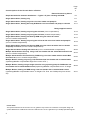
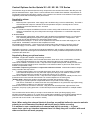
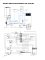
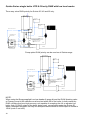
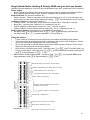
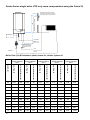
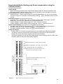
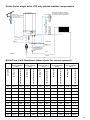
1
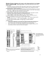
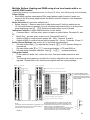
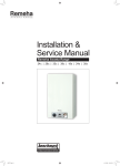
Remeha Quinta Series
Suggested Schematics
with Control and Power
Wiring details
100 M max.
Normal position for the inside sensor
mounted in a reference room within
the property (weather compensation
with inside temp adjustment)
Boiler
Terminal
Block
1.6M
2945
Boiler
Terminal
Block
Suggested height in Ref Room
Controller can only
be mounted in the boiler,
Outside Sensor
Mount in a sheltered position
on North facing wall
100 M max.
230v Supply
Condensate
QBS0021
Two to
Six Boi
lers
Gas
NOTE: Quinta 30
has Flow on the left
and Return on the
right
Flow
Return
Issue No. Date: 4 $XJXVW 2008
1
Page
No
3
Control Options for the Pre-mix Series of Boilers
External Controls by Others
Simple Quinta boiler domestic Installation — Typical “S” plan—Heating and DHW
4-5
Single Quinta boiler, Heating only
6-7
Single Quinta boiler, Heating only with a low loss header and pump kit
8-9
Single Quinta boiler, Heating & Priority DHW with a low loss header and pump or valve kit
10-11
Broag supplied controls
Single Quinta boiler, Heating only using the Celcia 20 (room compensation)
12-13
Single Quinta boiler, Heating only using the Celcia 20 (outside compensation)
14-15
Single Quinta boiler, Heating and Priority DHW using the Celcia 20 control
(room or outside compensation)
16-17
Single Quinta boiler, Heating only using the Celcia 20 with a low loss header and pump kit
(room or outside compensation)
18-19
Single Quinta boiler, Heating and Priority DHW using the Celcia 20 with a low loss header
and pump or valve kit (room or outside compensation)
20-21
Single Gas 210 boiler Heating with Celcia 20 (room or outside weather compensation)
28-29
Multiple Quinta boilers HTG only using a low loss header with the Celcia MC4 and Celcia 20
(room or outside compensation)
22-23
Multiple Quinta boilers HTG and Priority DHW using a low loss header with the Celcia MC4
and Celcia 20 (room or outside compensation)
24-25
Multiple Boilers, Heating only using a site fabricated low loss header with a rematic® 2945
(Optimising/Weather compensated Single Zone control HTG )
26-27
Multiple Boilers, Heating using a Single Calorifier using a primary pump for DHW and a low
loss header with a rematic® 2945 control (Optimising/Weather compensated control for Single
28-29
Multiple Boilers, Heating and DHW using a low loss header with a rematic® 2945 control
(Optimising/Weather compensated control for Single HTG Zone and DHW priority from all boilers)
30-31
PLEASE NOTE:
The layouts illustrated in this brochure are for guidance only and do not constitute a full system design. All
systems Mechanical and Electrical must be installed to the current regulations by a suitably qualified Engineer.
2
Control Options for the Quinta 30 / 45 / 65 / 85 / 115 Series
The Remeha range of Quinta boilers are fairly unique within the commercial market in that they are supplied as standard with an “Open Therm” control interface which enable direct weather compensation using Remeha single and multi boilers controls or the customer can choose to use external control options
supplied by others without affecting boiler performance
Supplied by others
On/off control
•
Boiler requires a permanent 230v supply and is enabled using a volt free switch/relay. The boiler’s
will modulate their output to maintain the flow temperature set point -normally 80c but can be
adjusted on the boiler between 20ºC and 90ºC
High/low control
•
As On/Off but requires an additional volt free contact -rarely used as this does not use the boilers
ability to modulate but may suit a fairly basic two stage compensator or a multi boiler sequence
controller
0-10 volt control
•
Boiler requires a permanent 230v supply and is enabled and modulated using a 0-10 volt signal
from a Building Management System or quality panel mounted optimiser / compensator. The
control can be flow temperature or percentage output based
Temperature based example - If 56ºC flow is required from the boiler the control will supply 5.6v, the
output will be modulated to maintain a flow temperature of 56ºC
Percentage based example - If the control logic requires that a boiler should be running at 33% the
control will supply 3.3v to the boiler - boiler will run at 33% output with a variable flow temperature
Applications- domestic / commercial and industrial installations, with a variety of heat emitters, DHW via
calorifiers or plate heat exchangers and installations where a variety of different temperatures zones are
required at the same time
Supplied by Broag as optional extras
Celcia 20 - Single boiler weather compensating controller
•
A simple programmable, room mounted thermostat / timer which uses a combination of outside,
room and flow temperature to vary the boiler output (flow temp) to suit weather conditions.
Celcia 20 is installed in a reference room, 7 day timer with multiple on/off periods, holiday function, frost
protection and manual overide (Can be mounted in a non-reference area i.e plant room when used in
weather compensated mode).
Celcia MC4 sequencing controller in conjunction with the Celcia 20 - Multi boiler weather compensating controller with step control
•
A simple programmable, room mounted thermostat / timer which uses a combination of outside,
room and flow temperature to vary the boiler output (flow temp) to suit weather conditions combined with the sequence controller to provide full control of up to 4 boilers
Celcia 20 is installed in a reference room, 7 day timer with multiple on/off periods, holiday function, frost
protection and manual override whilst the MC4 is mounted adjacent to the boiler group
Rematic 2945 - Multi boiler weather compensating controller with sequence control
•
Multi (up to 8) boiler optimiser compensator which can provide 2 timed heating zones
and uses a combination of outside, flow and room temperature to vary the boiler output (flow temp)
to suit weather conditions. Can also time control DHW.
Rematic 2945 control is mounted in one boiler, 7 day timer with 6 on/off periods, night set back, frost
protection, and pump cycling protection. Control will sequence and rotate lead boiler on multiple installations
This controller also has the ability to accept a remote extension timer (not Broag supply) which
will allow the heating system to run on day time compensation outside the normal timed settings without
need for access or interference to boiler or controller. Ideal for school lettings / night classes etc.
(volt free and must include a 1.5k resistor in series).
Note: When using the external interlock function on multiple boilers be sure to maintain
polarity to avoid unwanted feed back which will lead to faults occurring
It is unwise to use a combination of external and built in controls — in most
cases there can be no interface between them it is likely they will ‘FRQIOLFW’ZLWK each
other and neither will work properly .
3
Quinta Series single boiler HTG and DHW using a simple “S” plan layout
2 Channel
Time clock
Room Stat
Wiring Centre
230v Supply
Boiler
Terminal
Block
HTG Zone Valve
c/w end switches
Condensate
Gas
DHW Zone Valve
c/w end switches
Flow
NOTE: Quinta 30
has Flow on the left
and Return on the
right
Cylinder Stat
By-pass
valve
Zone
Regulating
Valves
Return
QBS0001
Wiring
Centre
NOTE: Some neutral and earth connections ommitted for clarity
8
9
System Pump
7
Cylinder
Thermostat
4
5
6
Calling
Satisfied
1
2
3
C
L
N
E
Calling
Satisfied
Simple Time
Clock with two live
switched outputs
L
N
DHW on 230v
HTG on 230v
C
Room Thermostat
End Switch
Close on valve
fully open
DHW Zone Valve
3 4 5
19 20
Boiler terminal block
End Switch
Close on valve
fully open
HTG Zone Valve
L
N
E
230v - 1 - 50
6 amp Switched Spur
QBW0001
4
Boiler Euro socket
(base of boiler)
LNE
Simple Quinta Boiler domestic Installation — Typical “S” plan—Heating and DHW
(Time and Temp control by others)
Power Supply
•
The boiler requires a permanent 230v single phase supply fused at 6 amps connected to the Euro plug (supplied with the boiler) socket is located on the underside of the boiler
Boiler Control Settings (see section 6.5 in technical documentation)
Set boiler code ! to required flow temp ie: 81 = 81ºC (system design requirements)
•
Set boiler code A to 11
•
Use the zone valve end switches to provide the volt free switch pair on 3 and 4 to
enable boiler.
•
Boiler output will vary between 18% part load set point (code &) and 100% full
load set point (code ^) to achieve the boiler flow set point (code !)
•
System Components (Not Broag supply)
•
Simple two channel time clock providing, 230v switched supplies to control heating
and domestic hot water eg. typical Honeywell ST699 or similar
•
System pump
•
Cylinder thermostat eg. typical Honeywell L641 or similar
•
Room thermostat eg. typical Honeywell T6360 or similar
•
HTG and DHW zone valves c/w a single end switch (closes on valve fully open)
eg. Honeywell V4043H or similar
•
Wiring centre
Note:
1.
Maintain polarity on all connections
2.
Some Neutral and Earth connections have been omitted for clarity
3.
The schematic is for guidance only and does not constitute a design
4.
Heating and hot water can be operated independently or simultaneously with this
layout provided the control selected will allow it
5
Quinta Series single boiler HTG only
Time / temp
Control
230v 6amp
Supply
Boiler
Terminal
Block
Condensate
Gas
NOTE: Quinta 30
has Flow on the left
and Return on the
right
Flow
Return
QBS0002
Boiler Flow (l/s) & Resistance (mbar) charts for various system Δ t
Quinta 30 - Nom
Output 28kW at
82/71
Quinta 65 - Nom
Output 61kW at
82/71
Quinta 85 - Nom
Output 84kW at
82/71
Quinta 115 - Nom
Output 107kW at
82/71
Nom Flow l/s
Boiler resistance mbar
Nom Flow l/s
Boiler resistance mbar
Nom Flow l/s
Boiler resistance mbar
Nom Flow l/s
Boiler resistance mbar
Nom Flow l/s
Boiler resistance mbar
System Δ t
6
Quinta 45 - Nom
Output 40kW at
82/71
20
0.34
140
0.48
90
0.72
130
1.01
140
1.28
250
19
0.35
155
0.51
100
0.77
144
1.06
155
1.35
277
18
0.37
173
0.53
111
0.81
160
1.12
173
1.42
309
17
0.4
194
0.56
125
0.86
180
1.18
194
1.51
346
16
0.42
219
0.6
141
0.91
203
1.26
219
1.60
391
15
0.45
249
0.64
160
0.97
231
1.34
249
1.71
444
14
0.48
286
0.68
184
1.04
265
1.44
286
1.83
510
13
0.51
331
0.74
213
1.12
308
1.55
331
1.97
592
12
0.56
389
0.8
250
1.22
361
1.67
389
2.13
694
11
0.61
460
0.87
300
1.33
430
1.83
460
2.33
826
10
0.67
560
0.96
360
1.46
520
2.01
560
2.56
1000
Single Quinta Boiler, Heating only
(Time and temperature control by others)
Power Supply
• Boiler requires a permanent 230v single phase supply fused at 6 amps connected to the Euro
plug (supplied with the boiler). Note: socket is located on the underside of the boiler
Boiler Interlocks (for pressure switches etc.)
• Safety Interlock - Remove exist link and fit Volt free switch pair on 10-14. If circuit broken the
boiler will go to a shut down mode displaying code B 26. Will restart when circuit is closed
Indication Controls (to report actual function)
• Common Alarm - volt free relay, opens on alarm or power failure Terminals 21 and 22
• Boiler Run - volt free relay, closes on run Terminals 23 and 24
• Output to BMS to confirm power supply OK - 230v Terminal 16 and N
• Output to BMS to confirm internal control supply OK - 24v ac Terminals 10 and 11
Boiler Control Settings (see section 6.5 in technical documentation)
• Set boiler code ! to required flow temp ie: 81 = 81ºC (system design requirements)
• For On/Off Control - Set boiler code A to 12, One volt free switch pair on 3 and 4 required
to enable boiler. Boiler output will vary between 18% part load set point (code A. &) ) and
100% full load set point A. (code ^) to achieve the boiler flow set point (code 1.)
• For Modulating Control - Set boiler code A to 42, for temperature output or code A to 52
percentage output. A 0 -10 volt control signal required by others to enable the
boiler and to perform the chosen control function
COMMON ALARM SIGNAL (VOLT FREE - MAX 230V 1AMP)
L
N
SYSTEM PUMP MAX 230V 1 AMP SUPPLY
Note if the system pump requires more than 1 Amp
use this as a 230v switch supply to a starter
SIGNAL TO BMS - 230v Supply live (if required)
o
13
EXTERNAL INTERLOCK (REMOVE LINK TO USE)
CARRIES A 24V AC SIGNAL
12
11 10 9 8 7 6 5 4 3 2
INTERLOCK LINK
(Fitted as Std)
24 23 22 21 20 19 18 17 16 15 14
1
QBW0002-A
BOILER RUN SIGNAL (VOLT FREE - MAX 230V 1AMP)
o
+
+
SIGNAL TO BMS - 24v CONTROL CIRCUIT OK (if required)
ON/OFF (not required if using 0-10v modulating)
o
MODULATING CONTROL (0-10V DC)
+
NOTE: Quinta 30 terminal numbers are reversed
7
Quinta Series single boiler HTG only with low loss header and pump kit
Time / Temp /
& System pump
Control
Boiler
Terminal
Block
Condensate
Gas
NOTE: Quinta 30
has Flow on the left
and Return on the
right
Flow
Return
QBS0004
Particularly suitable for refurbishment projects where existing system pump/s are to be
retained. For multi zone applications split the flow after the header and common up the
returns to the header
Quinta 30/45/65 Single Boiler header
35
System
Return
Quinta 85/115 Single and Two Boiler header
2 x 1" BSP(F)
Boiler side
QBS0005
150mm Square
Steel Tube
2 x 11/2" BSP(F)
System side
650
450 ctrs
Flow from
Boilers
Return to
Boilers
QBS0006
8
System
Flow
500 ctrs
Return to
Boiler
System
Flow
75
400
235 ctrs
Flow from
Boiler
330 ctrs
82.5
90 x 90 Square
Steel Tube
2 x 2/12" BSP(F)
Boiler side
System
Return
2 x 21/2" BSP(M)
System side
Single Quinta Boiler, Heating only with a low loss header and pump kit
(Time and temperature and system pump control by others)
Power Supply
• Boiler requires a permanent 230v single phase supply fused at 6 amps connected to the Euro
plug (supplied with the boiler). Note: socket is located on the underside of the boiler
Boiler Interlocks (for pressure switches etc.)
• Safety Interlock - Remove exist link and fit Volt free switch pair on 10-14. If circuit broken the
boiler will go to a shut down mode displaying code B 26. Will restart when circuit is closed
Indication Controls (to report actual function)
• Common Alarm - volt free relay, opens on alarm or power failure Terminals 21 and 22
• Boiler Run - volt free relay, closes on run Terminals 23 and 24
• Output to BMS to confirm power supply OK - 230v Terminal 16 and N
• Output to BMS to confirm internal control supply OK - 24v ac Terminals 10 and 11
Boiler Control Settings (see section 6.5 in technical documentation)
• Set boiler code ! to required flow temp ie: 81 = 81ºC (system design requirements)
• For On/Off Control - Set boiler code A to 12, One volt free switch pair on 3 and 4 required
to enable boiler. Boiler output will vary between 18% part load set point (code A. &) ) and
100% full load set point A. (code ^) to achieve the boiler flow set point (code 1)
• For Modulating Control - Set boiler code A to 42, for temperature output or code A to 52
for percentage output. A 0-10 volt control signal required by others to enable the
boiler and to perform the chosen control function
COMMON ALARM SIGNAL (VOLT FREE - MAX 230V 1AMP)
L
N
BOILER PUMP MAX 230V 1 AMP SUPPLY
SIGNAL TO BMS - 230v Supply live
o
13
EXTERNAL INTERLOCK (REMOVE LINK TO USE)
CARRIES A 24V AC SIGNAL
12
11 10 9 8
INTERLOCK LINK
(Fitted as Std)
24 23 22 21 20 19 18 17 16 15 14
7 6 5 3 2
1
QBW0002-B
BOILER RUN SIGNAL (VOLT FREE - MAX 230V 1AMP)
o
+
+
SIGNAL TO BMS - 24v Control Circuit OK
ON/OFF (not required if using 0-10v modulation)
o
MODULATING CONTROL (0-10V DC)
+
NOTE: Quinta 30 terminal numbers are reversed
9
Quinta Series single boiler HTG & Priority DHW with low loss header
Three way valve DHW priority for Quinta 30 / 45 and 65 only
230v 6am p
S upply
Tim e / tem p
C ontrol
S ensor cable 50 M m ax.
B oiler
Term inal
B lock
D H W Sensor or
Therm ostat
C ondensate
G as
N O T E: Q uinta 30
has Flow on the left
and R eturn on the
right
AB
B
Q S CH 0007
Flow
A
D H W D iverting valve
R eturn
Pump option DHW priority can be used on all Quinta range
230v 6amp
Supply
Time / temp
Control
Sensor cable 50 M max.
Boiler
Terminal
Block
DHW Sensor or
Thermostat
Condensate
Gas
NOTE: Quinta 30
has Flow on the left
and Return on the
right
Flow
Return
QSCH0008
NOTE:
When using the Broag supplied Low loss header & pump kit and the DHW diverting valve
or Primary pump kit the calorifier must be sited within 3M of the boiler. In both cases the
DHW cylinder must be a high recovery unit capable of accepting the full or adjusted (ref
boiler code C) DHW output of the boiler being used , except when using the Quinta 30
when a standard domestic unit may be used provided the boiler’s DHW output is limited to
15kW (code C set to25)
10
Single Quinta Boiler, Heating & Priority DHW using a Low Loss header
(Heating Time and temperature control by others with DHW available 24/7 temperature control by boiler)
Power Supply
• Boiler requires a permanent 230v single phase supply fused at 6 amps connected to the Euro
plug (supplied with the boiler). Note: socket is located on the underside of the boiler
Boiler Interlocks (for pressure switches etc.)
• Safety Interlock - Remove exist link and fit Volt free switch pair on 10-14. If circuit broken the
boiler will go to a shut down mode displaying code B 26. Will restart when circuit is closed
Indication Controls (to report actual function)
• Common Alarm - volt free relay, opens on alarm or power failure Terminals 21 and 22
• Boiler Run - volt free relay, closes on run Terminals 23 and 24
• Output to BMS to confirm power supply OK - 230v Terminal 16 and N
• Output to BMS to confirm internal control supply OK - 24v ac Terminals 10 and 11
Boiler Control Settings (see section 6.5 in technical documentation)
• Set boiler code ! to required flow temp ie: 81 = 81ºC (system design requirements)
• Set boiler code A to 11, Internal modulation - HTG on DHW on
•
Fitting the Control
•
Fit the control in a normally occupied reference room within the building being heated
•
The boiler’s internal wiring harness must be altered for the control to be recognised - Please
refer to the instructions supplied with the control package
•
Set up the controller to suit the design requirements and occupancy times for HTG in accordance with the instruction documents supplied
•
DHW Control, Diverting valve option - Set boiler code J to 00, (A=HTG and B=DHW), set
Primary Pump option - Set boiler code J to 01, set required DHW secondary temperature
code 3 to required temp ie: 55 = 55ºC
DHW Control, Primary Pump option - Set boiler code J to 01, set required DHW secondary temperature code 3 to required temp ie: 55 = 55ºC
24 23 22 21 20 19 18 17 16 15 14
COMMON ALARM SIGNAL (VOLT FREE - MAX 230V 1AMP)
L
N
BOILER PUMP MAX 230V 1 AMP SUPPLY
N
DHW VALVE OR PUMP MAX 230V 1 AMP SUPPLY
L
SIGNAL TO BMS - 230v Supply live
o
EXTERNAL INTERLOCK (REMOVE LINK TO USE)
CARRIES A 24V AC SIGNAL
12
11 10 9 8 7 6 5 4 3 2
1
QBW0002-C
BOILER RUN SIGNAL (VOLT FREE - MAX 230V 1AMP)
13
INTERLOCK LINK
(Fitted as Std)
•
o
+
+
SIGNAL TO BMS - 24v Control Circuit OK
DHW SENSOR or THERMOSTAT
ON/OFF (not required if using 0-10v modulation)
o
MODULATING CONTROL (0-10V DC)
+
NOTE: Quinta 30 terminal numbers are reversed
11
Quinta Series single boiler HTG only room compensation using the CelFLD
Normal position for the controller
mounted in a reference room within
the property (Room compensation )
1.6M
Boiler
Terminal
Block
Suggested height in Ref Room
100 M max.
230v Supply
Condensate
Gas
NOTE: Quinta 30
has Flow on the left
and Return on the
right
Flow
QBS0029
Return
Boiler Flow (l/s) & Resistance (mbar) charts for various system Δ t
Quinta 30 - Nom
Output 28kW at
82/71
Quinta 45 - Nom
Output 40kW at
82/71
Quinta 65 - Nom
Output 61kW at
82/71
Quinta 85 - Nom
Output 84kW at
82/71
Quinta 115 - Nom
Output 107kW at
82/71
Nom Flow l/s
Boiler resistance mbar
Nom Flow l/s
Boiler resistance mbar
Nom Flow l/s
Boiler resistance mbar
Nom Flow l/s
Boiler resistance mbar
Nom Flow l/s
0.34
140
0.48
90
0.72
130
1.01
140
1.28
250
19
0.35
155
0.51
100
0.77
144
1.06
155
1.35
277
18
0.37
173
0.53
111
0.81
160
1.12
173
1.42
309
17
0.4
194
0.56
125
0.86
180
1.18
194
1.51
346
16
0.42
219
0.6
141
0.91
203
1.26
219
1.60
391
15
0.45
249
0.64
160
0.97
231
1.34
249
1.71
444
14
0.48
286
0.68
184
1.04
265
1.44
286
1.83
510
13
0.51
331
0.74
213
1.12
308
1.55
331
1.97
592
12
0.56
389
0.8
250
1.22
361
1.67
389
2.13
694
11
0.61
460
0.87
300
1.33
430
1.83
460
2.33
826
10
0.67
560
0.96
360
1.46
520
2.01
560
2.56
1000
12
Boiler resistance mbar
System Δ t
20
Single Quinta Boiler, Heating only Room compensation using the
Celcia 20 control
(Timed/Compensated HTG)
Power Supply
• Boiler requires a permanent 230v single phase supply fused at 6 amps connected to the
Euro plug (supplied with the boiler). Note: socket is located on the underside of the boiler
Boiler Interlocks (for pressure switches etc.)
• Safety Interlock - Remove exist link and fit Volt free switch pair on 10 -14. If circuit broken
the boiler will go to a shut down mode displaying code B 26. Will restart when circuit is
closed
Indication Controls (to report actual function)
• Common Alarm - volt free relay, opens on alarm or power failure Terminals 21 and 22
• Boiler Run - volt free relay, closes on run Terminals 23 and 24
• Output to BMS to confirm power supply OK - 230v Terminal 16 and N
• Output to BMS to confirm internal control supply OK - 24v ac Terminals 10 and 11
Boiler Control Settings (see section 6.5 in technical documentation)
• Set boiler code ! to required flow temp ie: 81 = 81ºC (system design requirements)
• Set boiler code A to 12, Internal modulation - HTG on DHW off
• Set boiler Interface selection code 9. (to 00 (Internal Interface)
Fitting the Control
•
Fit the control in a normally occupied reference room within the building being heated
•
The boiler’s internal wiring harness must be altered for the control to be recognised Please refer to the instructions supplied with the control package
•
Set up the controller to suit the design requirements and occupancy times for HTG in accordance with the instruction documents supplied
COMMON ALARM SIGNAL (VOLT FREE - MAX 230V 1AMP)
L
N
SYSTEM PUMP MAX 230V 1 AMP SUPPLY
Note if the system pump requires more than 1 Amp
use this as a 230v switch supply to a starter
o
13
EXTERNAL INTERLOCK (REMOVE LINK TO USE)
CARRIES A 24V AC SIGNAL
12
11 10 9 8 7 6 5 4 3 2
INTERLOCK LINK
(Fitted as Std)
24 23 22 21 20 19 18 17 16 15 14
BOILER RUN SIGNAL (VOLT FREE - MAX 230V 1AMP)
+
Control mounted in ref room
OT-Bus
DIGI
1
QBW0017
NOTE: Quinta 30 terminal numbers are reversed
13
Quinta Series single boiler HTG only outside weather compensation
1.6M
Outside Sensor
Mount in a sheltered position
on North facing wall
O/S weather compensation
Boiler
Terminal
Block
Normal position for the controller
mounted in a reference room within
the property (room compensation)
Suggested height in Ref Room
100 M max.
230v Supply
100 M max.
Condensate
Gas
NOTE: Quinta 30
has Flow on the left
and Return on the
right
Flow
QBS0009
Return
Boiler Flow (l/s) & Resistance (mbar) charts for various system Δ t
Quinta 30 - Nom
Output 28kW at
82/71
Quinta 45 - Nom
Output 40kW at
82/71
Quinta 65 - Nom
Output 61kW at
82/71
Quinta 85 - Nom
Output 84kW at
82/71
Quinta 115 - Nom
Output 107kW at
82/71
Nom Flow l/s
Boiler resistance mbar
Nom Flow l/s
Boiler resistance mbar
Nom Flow l/s
Boiler resistance mbar
Nom Flow l/s
Boiler resistance mbar
Nom Flow l/s
Boiler resistance mbar
System Δ t
20
0.34
140
0.48
90
0.72
130
1.01
140
1.28
250
19
0.35
155
0.51
100
0.77
144
1.06
155
1.35
277
18
0.37
173
0.53
111
0.81
160
1.12
173
1.42
309
17
0.4
194
0.56
125
0.86
180
1.18
194
1.51
346
16
0.42
219
0.6
141
0.91
203
1.26
219
1.60
391
15
0.45
249
0.64
160
0.97
231
1.34
249
1.71
444
14
0.48
286
0.68
184
1.04
265
1.44
286
1.83
510
13
0.51
331
0.74
213
1.12
308
1.55
331
1.97
592
12
0.56
389
0.8
250
1.22
361
1.67
389
2.13
694
11
14
10
0.61
460
0.87
300
1.33
430
1.83
460
2.33
826
0.67
560
0.96
360
1.46
520
2.01
560
2.56
1000
14
Single Quinta Boiler, Heating only outside weather compensation with
Celcia 20
(Optimising/Weather compensated HTG )
Power Supply
• Boiler requires a permanent 230v single phase supply fused at 6 amps connected to the Euro
plug (supplied with the boiler). Note: socket is located on the underside of the boiler
Boiler Interlocks (for pressure switches etc.)
• Safety Interlock - Remove exist link and fit Volt free switch pair on 10-14. If circuit broken the
boiler will go to a shut down mode displaying code B 26. Will restart when circuit is closed
Indication Controls (to report actual function)
• Common Alarm - volt free relay, opens on alarm or power failure Terminals 21 and 22
• Boiler Run - volt free relay, closes on run Terminals 23 and 24
• Output to BMS to confirm power supply OK - 230v Terminal 16 and N
• Output to BMS to confirm internal control supply OK - 24v ac Terminals 10 and 11
Boiler Control Settings (see section 6.5 in technical documentation)
• Set boiler code ! to required flow temp ie: 81 = 81ºC (system design requirements)
• Set boiler code A to 12, Internal modulation - HTG on DHW off
• Set boiler Interface selection code 9. (to 00 (Internal Interface)
Fitting the Control
•
Fit the control in a normally occupied reference room within the building being heated
•
The boiler’s internal wiring harness must be altered for the control to be recognised - Please
refer to the instructions supplied with the control package
•
Install the outside sensor (ZAF 250) on a North facing wall in a sheltered position and connect to terminals 5 and 6
Set up the controller to suit the design requirements and occupancy times for HTG in accordance with the instruction documents supplied
24 23 22 21 20 19 18 17 16 15 14
BOILER RUN SIGNAL (VOLT FREE - MAX 230V 1AMP)
COMMON ALARM SIGNAL (VOLT FREE - MAX 230V 1AMP)
L
N
SYSTEM PUMP MAX 230V 1 AMP SUPPLY
Note if the system pump requires more than 1 Amp
use this as a 230v switch supply to a starter
o
13
EXTERNAL INTERLOCK (REMOVE LINK TO USE)
CARRIES A 24V AC SIGNAL
12
11 10 9 8 7 6 5 4 3 2
INTERLOCK LINK
(Fitted as Std)
•
DHW sensor or thermostat (if required)
+
Control mounted in ref room
Outside sensor
OT-Bus
DIGI
1
QBW0018
NOTE: Quinta 30 terminal numbers are reversed
15
Quinta Series single boiler HTG with DHW priority
Heating room or outside weather compensated with the Celcia 20
Three way valve DHW priority for Quinta 30 / 45 and 65 only
1.6M
Sensor cable 50 M max.
Boiler
Terminal
Block
Normal position for the controller
mounted in a reference room within
the property (room compensation)
Suggested height in Ref Room
100 M max.
Outside Sensor
Mount in a sheltered position
on North facing wall
O/S weather compensation
230v Supply
100 M max.
Condensate
DHW Sensor or
Thermostat
Gas
NOTE: Quinta 30
has Flow on the left
and Return on the
right
AB
Flow
B
A
Return
QBS0030
Pump option DHW priority can be used on all Quinta range
1.6M
Boiler
Terminal
Block
Normal position for the controller
mounted in a reference room within
the property (weather compensation)
Suggested height in Ref Room
Outside Sensor
Mount in a sheltered position
on North facing wall
100 M max.
230v Supply
DHW Sensor or
Thermostat
100 M max.
Condensate
Gas
NOTE: Quinta 30
has Flow on the left
and Return on the
right
QBS0031
Flow
Return
NOTE:
For room compensation only outside sensor is not required — fit O/S sensor (ZAF 250) for outside
weather compensation
The DHW cylinder must be a high recovery unit capable of accepting the full or adjusted DHW output of the boiler being used boiler code C , except when using the Quinta 30 when a standard domestic unit may be used provided the boiler’s DHW output is limited to 15kW (code C set to25)
When not using a Low Loss header the heating and DHW pumps must be capable of overcoming
the combined resistance of the boiler, system pipework and heat emitters.
By using a Low Loss header layout as detailed on page 18 the pumps can be sized without an allowance for the boiler resistance (particularly useful on refurbishment projects)
Non return valves should be used to prevent circulation where not required
If thermostatic valves are used on the heating system a bypass my be necessary to prevent the
pump from operating against a closed head should they all be closed (alternately do not fit a TRV
on one of the radiators in the system)
16
Single Quinta Boiler, room or weather compensated Heating
with Priority DHW using the Celcia 20
(Optimising/Weather compensated HTG with timed DHW)
Power Supply
• Boiler requires a permanent 230v single phase supply fused at 6 amps connected to the Euro
plug (supplied with the boiler). Note: socket is located on the underside of the boiler
Boiler Interlocks (for pressure switches etc.)
• Safety Interlock - Remove exist link and fit Volt free switch pair on 10-14. If circuit broken the
boiler will go to a shut down mode displaying code B 26. Will restart when circuit is closed
Indication Controls (to report actual function)
• Common Alarm - volt free relay, opens on alarm or power failure Terminals 21 and 22
• Boiler Run - volt free relay, closes on run Terminals 23 and 24
• Output to BMS to confirm power supply OK - 230v Terminal 16 and N
• Output to BMS to confirm internal control supply OK - 24v ac Terminals 10 and 11
Boiler Control Settings (see section 6.5 in technical documentation)
• Set boiler code ! to required flow temp ie: 81 = 81ºC (system design requirements)
• Set boiler code A to 11, Internal modulation - HTG on DHW on
• Set boiler Interface selection code ( to 00 (Internal Only)
Fitting the Control
•
Fit the control in a normally occupied reference room within the building being heated
•
The boiler’s internal wiring harness must be altered for the control to be recognised - Please
refer to the instructions supplied with the control package
•
Set up the controller to suit the design requirements and occupancy times for HTG in accordance with the instruction documents supplied
•
Install the outside sensor (ZAF 250) on a North facing wall in a sheltered position and connect to terminals 5 and 6
•
DHW Control, Diverting valve option - Set boiler code J to 00, (A=HTG and B=DHW), set
Primary Pump option - Set boiler code J to 01, set required DHW secondary temperature
code 3 to required temp ie: 55 = 55ºC
COMMON ALARM SIGNAL (VOLT FREE - MAX 230V 1AMP)
L
N
L
N
SYSTEM PUMP MAX 230V 1 AMP SUPPLY
DHW VALVE OR PUMP MAX 230V 1 AMP SUPPLY
Note : if the system pump/HWS requires more than 1 Amp
use this as a 230v switch supply to a starter
o
13
EXTERNAL INTERLOCK (REMOVE LINK TO USE)
CARRIES A 24V AC SIGNAL
12
11 10 9 8 7 6 5 4 3 2
INTERLOCK LINK
(Fitted as Std)
24 23 22 21 20 19 18 17 16 15 14
BOILER RUN SIGNAL (VOLT FREE - MAX 230V 1AMP)
DHW SENSOR or THERMOSTAT
+
Control mounted in ref room
Outside sensor
OT-Bus
DIGI
1
QBW0018
NOTE: Quinta 30 terminal numbers are reversed
17
Quinta Series single boiler HTG only using a low loss header
Heating—room or outside weather compensated with the Celcia 20
Normal position for the controller
mounted in a reference room within
the property (room compensation)
Boiler
Terminal
Block
Suggested height in Ref Room
1.6M
Outside Sensor
Mount in a sheltered position
on North facing wall
100 M max.
230v Supply
100 M max.
Condensate
Gas
NOTE: Quinta 30
has Flow on the left
and Return on the
right
QBS0032
Flow
Return
Particularly suitable for refurbishment projects where existing system pump/s are to be retained. For multi zone applications split the flow after the header and common up the returns to the header.
Note: System pump is controlled using a switch signal from the same connections as the
boiler pump terminal strip Nos 19 and 20, if the combined rating of both pumps is more
than 1 amp a starter must be used on the system pump
Quinta 30/45/65 Single Boiler header
Quinta 85 /115 Single Boiler header
90 x 90 Square
Steel Tube
System
Return
Return to
Boilers
2 x 1" BSP(F)
Boiler side
QBS0005
18
2 x 11/2" BSP(F)
System side
QBS0006
500 ctrs
35
Flow from
Boilers
System
Flow
450 ctrs
Return to
Boiler
System
Flow
650
400
235 ctrs
Flow from
Boiler
330 ctrs
82.5
75
150mm Square
Steel Tube
2 x 2/12" BSP(F)
Boiler side
System
Return
2 x 21/2" BSP(M)
System side
Single Quinta Boiler, room or weather compensated Heating only using
a low loss header and pump kit with the Celcia 20 (Optimising/Weather compensated HTG)
Power Supply
• Boiler requires a permanent 230v single phase supply fused at 6 amps connected to the Euro
plug (supplied with the boiler). Note: socket is located on the underside of the boiler
Boiler Interlocks (for pressure switches etc.)
• Safety Interlock - Remove exist link and fit Volt free switch pair on 10-14. If circuit broken the
boiler will go to a shut down mode displaying code B 26. Will restart when circuit is closed
Indication Controls (to report actual function)
• Common Alarm - volt free relay, opens on alarm or power failure Terminals 21 and 22
• Boiler Run - volt free relay, closes on run Terminals 23 and 24
• Output to BMS to confirm power supply OK - 230v Terminal 16 and N
• Output to BMS to confirm internal control supply OK - 24v ac Terminals 10 and 11
Boiler Control Settings (see section 6.5 in technical documentation)
• Set boiler code 1. to required flow temp ie: 81 = 81ºC (system design requirements)
• Set boiler code A to 12, Internal modulation - HTG on DHW off
• Set boiler code 2 to 15,pump run on to 15 minutes
• Set boiler Interface selection code 9. (to 00 (Internal Interface)
Fitting the Control
•
Fit the control in a normally occupied reference room within the building being heated
•
The boiler’s internal wiring harness must be altered for the control to be recognised - Please
refer to the instructions supplied with the control package
•
Install the outside sensor (ZAF 250) on a North facing wall in a sheltered position and connect to terminals 5 and 6
Set up the controller to suit the design requirements and occupancy times for HTG in accordance with the instruction documents supplied
24 23 22 21 20 19 18 17 16 15 14
BOILER RUN SIGNAL (VOLT FREE - MAX 230V 1AMP)
COMMON ALARM SIGNAL (VOLT FREE - MAX 230V 1AMP)
L
N
BOILER & SYSTEM PUMP MAX 230V 1 AMP SUPPLY
Note: If the system pumps requires more than 1 Amp
use this as a 230v switch supply to a starter.
o
13
EXTERNAL INTERLOCK (REMOVE LINK TO USE)
CARRIES A 24V AC SIGNAL
12
11 10 9 8 7 6 5 4 3 2
INTERLOCK LINK
(Fitted as Std)
•
+
Control mounted in ref room
Outside sensor
OT-Bus
DIGI
1
QBW0021
NOTE: Quinta 30 terminal numbers are reversed
19
Quinta Series single boiler HTG & DHW using a low loss header
Heating—room or outside weather compensated with the Celcia 20
Three way valve DHW priority for Quinta 30 / 45 and 65 only
1.6M
Outside Sensor
Mount in a sheltered position
on North facing wall
O/S weather compensation
100 M max.
Normal position for the controller
mounted in a reference room within
the property (room compensation)
Suggested height
in Ref Room
100 M max.
230v 6amp
Supply
100 M max.
Boiler
Terminal
Block
Summer / Winter
switch
(not Broag Supply)
DHW Sensor or
Thermostat
Condensate
Gas
NOTE: Quinta 30
has Flow on the left
and Return on the
right
AB
B
QSCH0033
Flow
A
Return
DHW Diverting valve
Pump option DHW priority can be used on all Quinta range
1.6M
100 M max.
Normal position for the controller
mounted in a reference room within
the property (room compensation)
Suggested height
in Ref Room
100 M max.
230v 6amp
Supply
Outside Sensor
Mount in a sheltered position
on North facing wall
O/S weather compensation
100 M max.
Boiler
Terminal
Block
Summer / Winter
switch
(not Broag Supply)
DHW Sensor or
Thermostat
Condensate
Gas
NOTE: Quinta 30
has Flow on the left
and Return on the
right
Flow
Return
QSCH0033
NOTE:
For room compensation only outside sensor is not required — fit O/S sensor (ZAF 250) for outside
weather compensation
The DHW cylinder must be a high recovery unit capable of accepting the full or adjusted DHW output of the boiler being used boiler code C , except when using the Quinta 30 when a standard domestic unit may be used provided the boiler’s DHW output is limited to 15kW (code C set to25)
When not using a Low Loss header the heating and DHW pumps must be capable of overcoming
the combined resistance of the boiler, system pipework and heat emitters.
By using a Low Loss header layout as detailed on page 18 the pumps can be sized without an allowance for the boiler resistance (particularly useful on refurbishment projects)
Non return valves should be used to prevent circulation where not required
If thermostatic valves are used on the heating system a bypass my be necessary to prevent the
pump from operating against a closed head should they all be closed (alternately do not fit a TRV
on one of the radiators in the system)
20
Single Quinta Boiler, room or weather compensated Heating with
Priority DHW using the Celcia 20
(Optimising/Weather compensated HTG with timed DHW)
Power Supply
• Boiler requires a permanent 230v single phase supply fused at 6 amps connected to the Euro
plug (supplied with the boiler). Note: socket is located on the underside of the boiler
Boiler Interlocks (for pressure switches etc.)
• Safety Interlock - Remove exist link and fit Volt free switch pair on 10-14. If circuit broken the
boiler will go to a shut down mode displaying code B 26. Will restart when circuit is closed
Indication Controls (to report actual function)
• Common Alarm - volt free relay, opens on alarm or power failure Terminals 21 and 22
• Boiler Run - volt free relay, closes on run Terminals 23 and 24
• Output to BMS to confirm power supply OK - 230v Terminal 16 and N
• Output to BMS to confirm internal control supply OK - 24v ac Terminals 10 and 11
Boiler Control Settings (see section 6.5 in technical documentation)
• Set boiler code ! to required flow temp ie: 81 = 81ºC (system design requirements)
• Set boiler code A to 11, Internal modulation - HTG on DHW on
• Set boiler Interface selection code ( to 00 (Internal Interface)
Fitting the Control
•
Fit the control in a normally occupied reference room within the building being heated
•
The boiler’s internal wiring harness must be altered for the control to be recognised - Please
refer to the instructions supplied with the control package
•
Set up the controller to suit the design requirements and occupancy times for HTG in accordance with the instruction documents supplied
•
DHW Control, Diverting valve option - Set boiler code J to 00, (A=HTG and B=DHW), set
Primary Pump option - Set boiler code J to 01, set required DHW secondary temperature
code 3 to required temp ie: 55 = 55ºC
COMMON ALARM SIGNAL (VOLT FREE - MAX 230V 1AMP)
L
N
L
N
Note: if the system pump/DHW requires more than 1 Amp
use this as a 230v switch supply to a starter.
SYSTEM PUMP MAX 230V 1 AMP SUPPLY
DHW VALVE OR PUMP MAX 230V 1 AMP SUPPLY
o
13
EXTERNAL INTERLOCK (REMOVE LINK TO USE)
CARRIES A 24V AC SIGNAL
12
11 10 9 8 7 6 5 4 3 2
INTERLOCK LINK
(Fitted as Std)
24 23 22 21 20 19 18 17 16 15 14
BOILER RUN SIGNAL (VOLT FREE - MAX 230V 1AMP)
DHW SENSOR or THERMOSTAT
+
Control mounted in ref room
Outside sensor
OT-Bus
DIGI
1
QBW0018
NOTE: Quinta 30 terminal numbers are reversed
21
Quinta Series Multiple boiler HTG only using a low loss header outside
weather compensated with the Celcia MC4 and Celcia 20
Normal position for the Celcia 20
mounted in a reference room within
the property (weather compensation)
100 M max.
1.6M
Boiler
Terminal
Block
Boiler
Terminal
Block
Celcia MC4
Suggested height in Ref Room
Outside Sensor
Mount in a sheltered position
on North facing wall
100 M max.
230v Supply
Condensate
Gas
Four B
oilers
NOTE: Quinta 30
has Flow on the left
and Return on the
right
Flow
Htg Flow
Sensor
Two to
QBS0035
Return
Site fabricated Multi Boiler Low Loss Header (Not supplied by Broag-Remeha )
F
60mm Min
F
F
"A"
Boiler Side
"B"
System Side
R
NOTE:
Boiler circulating pumps (sized for a nominal flow rate at 15ºC Δt) can be supplied by
Broag as an option (Primary Pump Kit),
provided that the header is sited within 1
meter of the last boiler.
For boiler pump selection where header
distances are greater or a different primary
operating Δ t is required please refer to the
tables on page 6 of this booklet for details
of Boiler nominal flow rates and resistances
at various system Δ t.
R
60mm Min
R
Header is based on an “open tube” design
QBS0020
Quinta 30/45
No of Boilers
22
Quinta 65/85
Quinta 115
2
3
4
2
3
4
2
3
4
Low Loss Header Dia mm
100
125
150
150
200
200
200
250
250
Connecting pipe work mm
32
50
65
65
80
100
80
100
125
Dimension “A” mm
300
375
450
450
600
600
600
750
750
Dimension “B” mm
350
425
500
500
650
650
650
800
800
Multi Quinta Boiler, weather compensated Heating only using a site
fabricated low loss header with the Celcia MC4 and Celcia 20
(Optimising/Weather compensated HTG)
Power Supply
Boiler requires a permanent 230v single phase supply fused at 6 amps connected to the Euro
plug (supplied with the boiler). Note: socket is located on the underside of the boiler
Boiler Interlocks (for pressure switches etc.)
• Safety Interlock - Remove exist link and fit Volt free switch pair on 10-14. If circuit broken the
boiler will go to a shut down mode displaying code B 26. Will restart when circuit is closed
Indication Controls (to report actual function)
• Common Alarm - volt free relay, opens on alarm or power failure Terminals 21 and 22
• Boiler Run - volt free relay, closes on run Terminals 23 and 24
• Output to BMS to confirm power supply OK - 230v Terminal 16 and N
• Output to BMS to confirm internal control supply OK - 24v ac Terminals 10 and 11
Boiler Control Settings (see section 6.5 in technical documentation)
• Set boiler code ! to required flow temp ie: 81 = 81ºC (system design requirements)
• Set boiler code A to 12, Internal modulation - HTG on DHW off
• Set boiler Interface selection code (to 00 (Internal Only)
Fitting the Control
•
Fit the Celcia 20 control in a normally occupied reference room within the building being
heated
•
Install the Celcia MC4 adjacent to the boiler group and connect as described in the fitting
instructions
•
The boiler’s internal wiring harness must be altered for the control to be recognised - Please
refer to the instructions supplied with the control package
•
Install the outside sensor (ZAF 200) on a North facing wall in a sheltered position and connect to terminals 13 and 14 on the MC4
•
Set up the controller to suit the design requirements and occupancy times for HTG in accordance with the instruction documents supplied
•
Outside Sensor
Mount in a sheltered position
on North facing wall
NOTE: Quinta 30 terminal numbers are reversed
L
N
Boiler pump when used with a low loss header
OT-Bus
DIGI
1 2 3 4 5
o
13
EXTERNAL INTERLOCK for Low/High pressure etc
(REMOVE LINK TO USE) CARRIES A 24V AC SIGNAL
12
11 10 9 8 7 6 5 4 3 2
INTERLOCK LINK
(Fitted as Std)
24 23 22 21 20 19 18 17 16 15 14
Boiler 1
Celcia 20 mounted in ref room
+
System Pump
Note if it requires more than 1 Amp
use this as a 230v switch supply to a starter
Switch spur unit
230v Supply
Rated at 3 amps
MC4
L N E E
17 18 19
1 2 3 4 5 6 7 8 9 10 11 12 13 14
1
4 3 2
1
Boiler 2
4 3 2
Flow Sensor
Mount on flow pipework to
register a common flow
temperature from the boilers
1
QBW0020
Boiler 3
For all other boiler wiring connections - indication signals and
interlocks etc
Please refer to the Technical Instructions provided with the boiler
4 3 2
1
Boiler 4
23
Quinta Series Multiple boiler HTG & Priority DHW using a site fabricated
low loss header with the Celcia MC4 and Celcia 20
Normal position for the Celcia 20
mounted in a reference room within
the property (weather compensation)
100 M max.
1.6M
Boiler
Terminal
Block
Boiler
Terminal
Block
Celcia MC4
Suggested height in Ref Room
Outside Sensor
Mount in a sheltered position
on North facing wall
100 M max.
230v Supply
DHW Sensor or
Thermostat
Condensate
Gas
Two to
Four B
o
ilers
NOTE: Quinta 30
has Flow on the left
and Return on the
right
Flow
Htg Flow
Sensor
Return
QSCH0036
(Not supplied by Broag-Remeha)
NOTE:
Boiler circulating pumps (sized for a nomiF
nal flow rate at 15ºC Δt) can be supplied by
60mm Min Broag as an option (Primary Pump Kit),
F
provided that the header is sited within 1
meter of the last boiler.
For boiler pump selection where header
distances are greater or a different primary
"B"
operating Δ t is required please refer to the
System Side
tables on page 6 of this booklet for details
of Boiler nominal flow rates and resistances
at various system Δ t.
Site fabricated Multi Boiler Low Loss Header
F
"A"
Boiler Side
R
R
60mm Min
R
Header is based on an “open tube” design
QBS0020
Quinta 30/45
No of Boilers
Quinta 65/85
Quinta 115
2
3
4
2
3
4
2
3
4
Low Loss Header Dia mm
100
125
150
150
200
200
200
250
250
Connecting pipe work mm
32
50
65
65
80
100
80
100
125
Dimension “A” mm
300
375
450
450
600
600
600
750
750
Dimension “B” mm
350
425
500
500
650
650
650
800
800
24
Multi Quinta Boiler, weather compensated Heating & Priority DHW using
a site fabricated low loss header with the Celcia MC4 and Celcia 20
(Optimising/Weather compensated HTG)
Power Supply
Boiler requires a permanent 230v single phase supply fused at 6 amps connected to the Euro
plug (supplied with the boiler). Note: socket is located on the underside of the boiler
Boiler Interlocks (for pressure switches etc.)
• Safety Interlock - Remove exist link and fit Volt free switch pair on 10-14. If circuit broken the
boiler will go to a shut down mode displaying code B 26. Will restart when circuit is closed
Indication Controls (to report actual function)
• Common Alarm - volt free relay, opens on alarm or power failure Terminals 21 and 22
• Boiler Run - volt free relay, closes on run Terminals 23 and 24
• Output to BMS to confirm power supply OK - 230v Terminal 16 and N
• Output to BMS to confirm internal control supply OK - 24v ac Terminals 10 and 11
Boiler Control Settings (see section 6.5 in technical documentation)
• Set boiler code ! to required flow temp ie: 81 = 81ºC (system design requirements)
• Set boiler code (boiler with calorfier only) A to 11, Internal modulation - HTG on DHW on
• Set boiler Interface selection code (to 00 (Internal Only)
Fitting the Control
•
Fit the Celcia 20 control in a normally occupied reference room within the building being
heated
•
Install the Celcia MC4 adjacent to the boiler group and connect as described in the fitting
instructions
•
The boiler’s internal wiring harness must be altered for the control to be recognised - Please
refer to the instructions supplied with the control package
•
Install the outside sensor (ZAF 200) on a North facing wall in a sheltered position and connect to terminals 13 and 14 on the MC4
•
Set up the controller to suit the design requirements and occupancy times for HTG in accordance with the instruction documents supplied
•
Outside Sensor
Mount in a sheltered position
on North facing wall
NOTE: Quinta 30 terminal numbers are reversed
L
N
Boiler pump when used with a low loss header
OT-Bus
DIGI
1 2 3 4 5
o
13
EXTERNAL INTERLOCK for Low/High pressure etc
(REMOVE LINK TO USE) CARRIES A 24V AC SIGNAL
12
11 10 9 8 7 6 5 4 3 2
INTERLOCK LINK
(Fitted as Std)
24 23 22 21 20 19 18 17 16 15 14
Boiler 1
Celcia 20 mounted in ref room
System Pump
Note if it requires more than 1 Amp
use this as a 230v switch supply to a starter
+
DHW Sensor
or Thermostat
Outside sensor
Switch spur unit
230v Supply
Rated at 3 amps
MC4
L N E E
17 18 19
1 2 3 4 5 6 7 8 9 10 11 12 13 14
1
4 3 2
1
Boiler 2
4 3 2
Flow Sensor
Mount on flow pipework to
register a common flow
temperature from the boilers
1
QBW0022
Boiler 3
For all other boiler wiring connections - indication signals and
interlocks etc
Please refer to the Technical Instructions provided with the boiler
4 3 2
1
Boiler 4
25
Normal position for the inside sensor
mounted in a reference room within
the property (weather compensation
with inside temp adjustment)
100 M max.
Boiler
Terminal
Block
1.6M
Boiler
Terminal
Block
2945
Suggested height in Ref Room
Controller can only
be mounted in the boiler,
Outside Sensor
Mount in a sheltered position
on North facing wall
100 M max.
230v Supply
Condensate
Gas
Six Bo
ilers
NOTE: Quinta 30
has Flow on the left
and Return on the
right
Flow
Htg Flow
Sensor
Two to
QBS0021
Return
Site fabricated Multi Boiler Low Loss Header (Not supplied by Broag-Remeha)
NOTE:
Boiler circulating pumps (sized for a nominal
flow rate at 15ºC ∆t) can be supplied by
Broag as an option (Primary Pump Kit), provided that the header is sited within 1 meter
of the last boiler.
For boiler pump selection where header distances are greater or a different primary operating ∆ t is required please refer to the
tables on page 4 of this booklet for details
of Boiler nominal flow rates and resistances
at various system ∆ t.
F
60mm Min
F
F
"A"
Boiler Side
"B"
System Side
R
R
60mm Min
R
QBS0020
Quinta 30/45
No of Boilers
26
Quinta 65/85
Quinta 115
2
3
4
2
3
4
2
3
4
Low Loss Header Dia mm
100
125
150
150
200
200
200
250
250
Connecting pipe work mm
32
50
65
65
80
100
80
100
125
Dimension “A” mm
300
375
450
450
600
600
600
750
750
Dimension “B” mm
350
425
500
500
650
650
650
800
800
Multiple Boilers, Heating only using a site fabricated low loss header
with a rematic® 2945 (Optimising/Weather compensated Dual Zone control HTG )
Power Supply
• Each boiler requires a permanent 230v single phase supply fused at 6 amps connected to
the Euro plug (supplied with the boiler) socket is located on the underside of the boiler
Boiler Interlocks (for pressure switches etc.)
• Safety Interlock - Remove exist link on each boiler and fit Volt free switch pair on 10-14 to
both boilers in parallel. If circuit is broken both boilers will go to a shut down mode displaying code B 26. Boiler will restart when circuit is closed
Indication Controls (to report actual function of each boiler)
• Common Alarm - volt free relay, opens on alarm or power failure Terminals 21 and 22
• Boiler Run - volt free relay, closes on run Terminals 23 and 24
• Output to BMS to confirm power supply OK - 230v Terminal 16 and N
• Output to BMS to confirm internal control supply OK - 24v ac Terminals 10 and 11
Boiler Control Settings (see section 6.5 in technical documentation)
• Set each boiler code ! to required flow temp ie: 81 = 81ºC (system design requirements)
• Set each boiler code A to 12, Internal modulation - HTG on DHW off
• Set each boiler Interface selection code ( to 01 (external interface)
Fitting the Control
•
Fit the control in boiler No 1, mount the room, flow and outside sensors as indicated
•
The boiler’s internal wiring harness must be altered for the control to be recognised - Please refer to the instructions supplied with the control package
•
Set up the controller to suit the design requirements and occupancy times for HTG
in accordance with the instruction documents supplied
Boiler No 2 to 6 Terminal Strip
Boiler No 1 Terminal Strip
As Boiler No 1
L
Earth
Boiler Pump
BOILER RUN SIGNAL (VOLT FREE - MAX 230V 1AMP)
COMMON ALARM SIGNAL (VOLT FREE - MAX 230V 1AMP)
N
Boiler wiring
harness
Flow
Sensor
The wiring diagram shown
is for the single heating zone
please refer to the instructions
in the control package for dual
heating zones.
12
Room
Sensor
System Pump
(Max 1 amp)
Quinta Series Only
Connect to No 2 on Boiler 2 - and No 2 on Boiler 3 etc
1
1
4 3 2
11 10 9 8 7 6 5 4 3 2
INTERLOCK LINK
X25
X25
Outside
Sensor
Pump cable supplied with control set
13
INTERLOCK LINK
24 23 22 21
24 23 22 21 2019 18 17 16 15 14
As Boiler No 1
Connect to No 1 on Boiler 2 - and No 1 on Boiler 3 etc
Rematic Control Wiring Plate supplied with Set
NOTE: Quinta 30 terminal numbers are reversed
If a heating extension timer is required a volt free switch
arrangement (electrical or clockwork controlled) can be
NOTE:
The Rematic Control Interface fitted to each boiler has a set connected across terminals 36 / 37 in series with a 1.5k
resistor as shown. NOT BROAG SUPPLY
of dip switches which must be set in accordance with the
Close the switch and the heating will run continuous on day
fitting instructions supplied with Control
time compensation (as set on the controller). Open the
switch and control will revert to the set timed function.
QBW0010
1.5k
Resistor
Overide
Switch
36
37
27
Boiler 3
Boiler 2
Boiler 1
100 M max.
Controller can only
be mounted in the boiler,
1.6M
230v Supply
2945
Boiler
Terminal
Block
Boiler
Terminal
Block
Boiler
Terminal
Block
NOTE: Quinta 30
has Flow on the left
and Return on the
right
Suggested height in Ref Room
100 M max.
Outside Sensor
Mount in a sheltered
position on
North facing wall
Normal position for the inside sensor
mounted in a reference room within
the property (weather compensation
with inside temp adjustment)
Condensate
Gas
Three
to
Six Bo
ilers
Sensor or
Thermostat
Flow
Htg Flow
Sensor
Return
Calorifier
QBS0027
Control logic
Set up the rematic® 2945 C3 K controller to suit the installation and building heat loss
response time it will provide timed, weather compensated heating with an optimum start
facility (uses inside and outside sensors to delay the on time as dictated by weather conditions). Timed / priority DHW with a boosted flow temperature for fast recovery provided a
high recovery calorifier is used.
Heating (Boilers 1 to 3)
During the timed on periods the heating will be day time weather compensated (in accordance with the heating curve programmed). The 2945 will directly control each boiler
modulating their output and calling as many as are required to achieve the desired comfort
conditions dictated by the compensation parameters
DHW (Boiler 1 only)
DHW takes priority over the heating system and on demand of the DHW sensor, the boiler
connected the calorifier will take control from the 2945, boost its flow temperature from the
compensated level determined by the 2945 control, to the boiler flow set point - code !
and energise the primary pump, at the same time will turn off the boiler pump
When the DHW demand is satisfied the boiler will shut down, de-energise the primary
pump and re-energise the boiler pump. The 2945 will take back control of the boiler and
call it in if necessary to satisfy the heating demand.
NOTE:
When using a Low loss header layout with the Broag DHW Primary pump kit the calorifier must
be sited within 3M of the boiler. The DHW cylinder must be a high recovery unit capable of accepting the full or adjusted (ref boiler code C) DHW output of the boiler being used , except
when using the Quinta 30 when a standard domestic unit may be used provided the boiler’s DHW
output is limited to 15kW (code C set to25)
28
Multiple Boilers, Heating using a Single Calorifier using a primary pump
for DHW and a low loss header with a rematic® 2945 control
(Optimising/Weather compensated control for Dual HTG Zone and DHW Priority from one boiler)
Each boiler requires a permanent 230v single phase supply fused at 6 amps connected
to the Euro plug (supplied with the boiler) socket is located on the underside of the
boiler
Boiler Interlocks (for pressure switches etc.)
• Safety Interlock - Remove exist link on each boiler and fit Volt free switch pair on 1014 to both boilers in parallel. If circuit is broken both boilers will go to a shut down mode
displaying code B 26. Boilers will restart when circuit is closed
Indication Controls (to report actual function of each boiler)
• Common Alarm - volt free relay, opens on alarm or power failure Terminals 21 and 22
• Boiler Run - volt free relay, closes on run Terminals 23 and 24
• Output to BMS to confirm power supply OK - 230v Terminal 16 and N
• Output to BMS to confirm internal control supply OK - 24v ac Terminals 10 and 11
Boiler Control Settings (see section 6.5 in technical documentation)
• Set each boiler code ! to required flow temp ie: 81 = 81ºC (system design requirements)
• Set each boiler code A to 11, Internal modulation - HTG and DHW on
• Set each boiler Interface selection code ( to 01 (external interface)
• DHW Control, Primary Pump option - Set boiler code J to 01, set required DHW
secondary temperature code 3 to required temp ie: 55 = 55ºC (set the 2945 DHW
to the same temperature setpoint).
Fitting the Control
•
Fit the control in boiler No1, mount the room, flow and outside sensors as indicated
•
The internal wiring harness on boiler No1 must be altered for the control to be recognised - Please refer to the instructions supplied with the control package
•
Set up the controller to suit the design requirements and occupancy times for HTG and
DHW in accordance with the instruction documents supplied
•
Boiler Pump
Earth
L
COMMON ALARM SIGNAL (VOLT FREE - MAX 230V 1AMP)
L
N
Outside
Sensor
DHW Primary
Pump
Flow
Sensor
12
12
12
11 10 9 8 7 6 5
DHW Sensor
or Thermostat
Quinta Series Only
1
1
1
Rematic Control Wiring Plate supplied with Set - will need to be
positioned to the right slightly to allow access to terminal block
Connect to No 2 on Boiler 2 - and No 2 on Boiler 3 etc
Connect to No 1 on Boiler 2 - and No 1 on Boiler 3 etc
NOTE: Quinta 30 terminal numbers are reversed
NOTE:
The Rematic Control Interface fitted to each boiler has a set
of dip switches which must be set in accordance with the
fitting instructions supplied with Control
QBW0015
The wiring
diagram shown
is for the single
heating zone
please refer to
the instructions
in the control
package for
dual
heating zones.
Room
Sensor
System Pump
(Max 1 amp)
4 3 2
11 10 9 8 7 6 5 4 3 2
11 10 9 8 7 6 5 4 3 2
INTERLOCK LINK
Boiler wiring
harness
X25
N
BOILER RUN SIGNAL (VOLT FREE - MAX 230V 1AMP)
13
13
13
INTERLOCK LINK
N
Boiler Pump
As Boiler No 1
X25
As Boiler No 1
L
Boiler No 1 Terminal Strip
As Boiler No 1
24 23 22 21 20 19 18 17 16 15 14
As Boiler No 1
24 23 22 21 2019 18 17 16 15 14
24 23 22 21 20 19 18 17 16 15 14
INTERLOCK LINK
Boiler No 2 Terminal Strip
Pump cable supplied with control set
Boiler No 3 Terminal Strip
(with Control over DHW demand)
If a heating extension timer is required a volt free switch
arrangement (electrical or clockwork controlled) can be
connected across terminals 36 / 37 in series with a 1.5k
resistor as shown. NOT BROAG SUPPLY
Close the switch and the heating will run continuous on day
time compensation (as set on the controller). Open the
switch and control will revert to the set timed function.
1.5k
Resistor
Overide
Switch
36
37
29
100 M max.
Normal position for the inside sensor
mounted in a reference room within
the property (weather compensation
with inside temp adjustment)
Boiler
Terminal
Block
1.6M
2945
Boiler
Terminal
Block
Suggested height in Ref Room
Controller can only
be mounted in the boiler,
Outside Sensor
Mount in a sheltered position
on North facing wall
100 M max.
Htg Flow
Sensor
DHW Sensor
System
Pump
230v Supply
Condensate
Two to
Six Bo
ilers
Gas
QBS0024
100 M max.
NOTE: Quinta 30
has Flow on the left
and Return on the
right
DHW
Pump
Flow
Return
Control logic
Set up the rematic® 2945 C3 K controller to suit the installation and building heat loss
response time and it will provide timed, weather compensated heating with an optimum
start facility (uses inside and outside sensors to delay the on time as dictated by
weather conditions) and timed/temperature controlled priority DHW with a boosted flow
temperature for fast recovery provided a high recovery calorifier is used.
Heating (All boilers available)
During the timed on periods the heating will be day time weather compensated (in accordance with the heating curve programmed). The 2945 will directly control each boiler
modulating their output and calling as many as are required to achieve the desired comfort conditions dictated by the compensation parameters
DHW (All boilers available)
DHW will take priority over heating and on demand of the DHW sensor the control will
turn on the Primary pump and boost the boiler flow temperature to the DHW primary
flow set point, if this set point is higher than the required heating flow set point
(determined by the compensator) the flow sensor will detect the rise in temperature and
compensate the heating via the 3 port valve.
When the DHW demand is satisfied the control will turn the primary pump off and reduce the flow temperature to the compensated level.
The 2945 controller can also operate the DHW and heating in parallel (both on or off
working indepently of each other) but if the DHW temperature drops below appox 30ºC
the DHW priority will again become active.
30
Multiple Boilers, Heating and DHW using a low loss header with a rematic® 2945 control
(Optimising/Weather compensated control for Dual HTG Zone and DHW priority from all boilers)
Power Supply
• Each boiler requires a permanent 230v single phase supply fused at 6 amps connected to the Euro plug (supplied with the boiler) socket is located on the underside
of the boiler
Boiler Interlocks (for pressure switches etc.)
• Safety Interlock - Remove exist link on each boiler and fit Volt free switch pair on
10-14 to both boilers in parallel. If circuit is broken both boilers will go to a shut down
mode displaying code B 26. Boilers will restart when circuit is closed
Indication Controls (to report actual function of each boiler)
•
Common Alarm - volt free relay, opens on alarm or power failure Terminals 21 and
22
•
Boiler Run - volt free relay, closes on run Terminals 23 and 24
•
Output to BMS to confirm power supply OK - 230v Terminal 16 and N
•
Output to BMS to confirm internal control supply OK - 24v ac Terminals 10 and 11
Boiler Control Settings (see section 6.5 in technical documentation)
•
Set each boiler code ! to required flow temp ie: 81 = 81ºC (system design requirements)
•
Set each boiler code A to 11, Internal modulation - HTG and DHW on
•
Set each boiler Interface selection code ( to 01 (external interface)
Fitting the Control
•
Fit the control in boiler No1, mount the room, flow and outside sensors as indicated
•
The internal wiring harness on boiler No1 must be altered for the control to be recognised - Please refer to the instructions supplied with the control package
Boiler No 2 to 6 Terminal Strip
24 23 22 21
As Boiler No 1
BOILER RUN SIGNAL (VOLT FREE - MAX 230V 1AMP)
COMMON ALARM SIGNAL (VOLT FREE - MAX 230V 1AMP)
Boiler Pump
Boiler wiring
harness
DHW
Sensor
Flow
Sensor
The wiring diagram shown
is for the single heating zone
please refer to the instructions
in the control package for dual
heating zones.
13
12
Room
Sensor
System Pump
(Max 1 amp)
DHW Pump
(Max 1 amp)
Quinta Series Only
Connect to No 2 on Boiler 2 - and No 2 on Boiler 3 etc
1
1
4 3 2
11 10 9 8 7 6 5 4 3 2
INTERLOCK LINK
X25
Outside
Sensor
X25
N
Earth
As Boiler No 1
L
Pump cable supplied with control set
24 23 22 21 2019 18 17 16 15 14
INTERLOCK LINK
Boiler No 1 Terminal Strip
Connect to No 1 on Boiler 2 - and No 1 on Boiler 3 etc
Rematic Control Wiring Plate supplied with Set
NOTE: Quinta 30 terminal numbers are reversed
If a heating extension timer is required a volt free switch
arrangement (electrical or clockwork controlled) can be
NOTE:
The Rematic Control Interface fitted to each boiler has a set connected across terminals 36 / 37 in series with a 1.5k
resistor as shown. NOT BROAG SUPPLY
of dip switches which must be set in accordance with the
Close the switch and the heating will run continuous on day
fitting instructions supplied with Control
time compensation (as set on the controller). Open the
switch and control will revert to the set timed function.
QBW0012
1.5k
Resistor
Overide
Switch
36
37
31
Remeha Quinta Series
Broag Ltd
Remeha House
Molly Millars Lane
Wokingham
Berkshire RG41 2QP
Tel : 0118 978 3434
Fax : 0118 978 6977
e Mail : [email protected]
Web Site :www.uk.remeha.com
The schematics in this brochure are for guidance only and do not constitute a design
The content in this brochure is based on the latest information available at date of
publication and may be subject to revisions.
We reserve the right to continuous development in both design and manufacture, therefore
any changes to the technology or equipment employed may not be retrospective nor may
we be obliged to adjust earlier supplies accordingly
32
Quinta\Installation.Issue8 – 04-08-2008-Schematics booklet.pub.sj