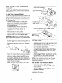
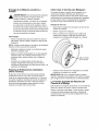
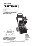
1
Owner's Manual
CRRFTSMRN°
6.5 HORSEPOWER
2400 PSI
2.2 GPM
PRESSUR
WASHER
Model No. 580.767302
HOURS:
Mon.-
CAUTION"
•
•
•
•
•
•
Fri. 8 a.m. to 5 p.m. (CT)
Before
using this product,
read this manual and follow all Safety
Rules and Operating Instructions.
SEARS,
ROEBUCK
and CO.,
Hoffman
Estates,
IL 60179
Visit our Craftsman website: www.sears.com/craftsman
Part No. 190821GS
Draft 2 (06/10/2002)
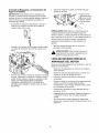
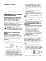
Safety
Assembly
Operation
Maintenance
Parts
Espahol
U.S.A.
WARRANTY ...................................
2
STORAGE .................................
SAFETY RULES ..............................
2-3
TROUBLESHOOTING
ASSEMBLY ..................................
4-6
REPLACEMENT
OPERATION ................................
7-10
MAINTENANCE
............................
SPECIFICATIONS
11-14
.............................
LIMITED
11
WARRANTY
15-16
..........................
17
PARTS ......................
18-25
EMISSION CONTROL WARRANTY
................
ESPANOL .................................
27-43
HOW TO ORDER PARTS ...............
ON CRAFTSMAN
PRESSURE
26
BACK PAGE
WASHER
For one year from the date of purchase, when this Craftsman pressure washer is maintained and operated
according to the instructions in the owner's manual, Sears will repair, free of charge, any defect in material and
workmanship.
If this washer is used for commercial purposes, this warranty applies for only 90 days from the date of purchase.
If this pressure washer is used for rental purposes, this warranty applies for only 30 days after date of purchase.
This warranty does not cover:
•
Expendable items such as spark plugs or air filters, which become worn during normal use.
•
Repairs necessary because of operator abuse or negligence, including damage resulting from no water being
supplied to pump or failure to maintain the equipment according to the instructions contained in the owner's
manual.
Warranty service is available by returning the pressure washer to the nearest Sears service center or dealer in
the United States.
This warranty gives you specific legal rights and you may also have other rights, which vary from state to state.
Sears, Roebuck
and Co., Dept. 817WA,
_
The engine exhaust from this product contains
chemicals known to the State of California to
cause cancer, birth defects, or other
reproductive harm.
CAUTION!
When setting up, transporting,
adjusting or making repairs to your pressure
washer, always disconnect the spark plug wire
from the spark plug and place the wire where it
cannot contact spark plug.
DANGER! Engine exhaust gases contain
DEADLY carbon monoxide gas. This dangerous
gas, if breathed in sufficient concentrations, can
cause unconsciousness or even death. Operate
this equipment only in the open air where
adequate ventilation is available.
Hoffman
Estates,
IL 60179
ARNING!
is highly FLAMMABLE
and
its vapors Gasoline
are EXPLOSIVE.
Do Not permit
smoking, open flames, sparks or heat in the
vicinity while handling gasoline. Avoid spilling
gasoline on a hot engine. Allow unit to cool
before refueling. Comply with all laws regulating
storage and handling of gasoline.
Read this manual carefully and become familiar
with your pressure washer. Know its applications,
its limitations, and any hazards involved.
•
Locate this pressure washer in areas away from
combustible materials, combustible fumes or dust.
•
The pressure equipment is designed to be used
with Sears authorized parts ONLY. If you use this
equipment with parts that do not comply with
minimum specifications, the user assumes all risks
and liabilities.
• Somechemicalsordetergentsmaybe harmfulif
inhaledor ingested,causingseverenausea,
faintingor poisoning.
Theharmfulelementsmay
causepropertydamageor severeinjury.
• Do NotallowCHILDREN
tooperatethe pressure
washerat anytime.
• Operateengineonlyatgovernedspeed.Running
theengineatexcessivespeedsincreases
the
hazardof personalinjury.DoNottamperwithparts
whichmayincreaseor decreasethe governed
speed.
• Do Notwearlooseclothing,jewelryor anything
thatmaybecaughtin thestarteror otherrotating
parts.
• Beforestartingthe pressurewasherincold
weather,checkall partsoftheequipment
andbe
sureicehasnotformedthere.See"Storage"on
page15forcoldweatherprotection.
• Neverusea spraygunwhichdoesnothavea
triggerlockor triggerguardin placeandinworking
order.
• Keepthe hoseconnected
to machineorthe spray
gunwhilethe systemis pressurized.
Disconnecting
thehosewhilethe unitis pressurized
is dangerous.
• Neveroperateunitswithbrokenor missingparts,
or withoutprotectivehousingor covers.
• Checkthefuelsystemforleaksor signsof
deterioration,
suchaschafedor spongyhose,
looseor missingclamps,or damagedtankor cap.
Correctalldefectsbeforeoperating
the pressure
washer.
• Do Notsprayflammableliquids.
• Usea respiratoror maskwheneverthereis a
chancethatvaporsmaybeinhaled.Readall
instructions
withmasksoyouarecertainthe mask
willprovidethe necessaryprotection
against
inhalingharmfulvapors.
• Neveraimthespraygunat people,animalsor
plants.Thepressurestreamofwaterthatthis
equipment
producescanpierceskinandits
underlying
tissues,leadingto seriousinjuryand
possibleamputation.
• Neverallowanypartofthe bodytocomein
contactwiththefluidstream.Do Notcomein
contactwitha fluidstreamcreatedby a leakinthe
highpressurehose.
• Alwaysweareyeprotection
whenyouusethis
equipment
orwhenyouareinthevicinitywhere
theequipment
is in use.
• Highpressurespraycancausepaintchipsor other
particlesto becomeairborne.
,_
• DoNot operatethe pressurewasherabovethe
ratedpressure.
• Nevermovethemachineby pullingonthe high
pressurehose.Usethehandleprovidedonthe
unit.
• Alwaysbecertainthe spraygun,nozzlesand
accessories
arecorrectlyattached.
• DoNot securethe sprayguninthe (open)
position.
• Highpressurespraymaydamagefragileitems
includingglass.DoNot pointspraygunat glass
wheninthejet spraymode.
• Holdthespraygunfirmlyinyourhandbeforeyou
starttheunit.Failureto doso couldresultinan
injuryfroma whippingspraygun.Do Notleavethe
spraygununattended
whilethe machineis
running.
• Thecleaningareashouldhaveadequateslopes
anddrainageto reducethe possibility
ofa fall due
to slipperysurfaces.
• Keepwatersprayawayfromelectricwiringor fatal
electricshockmayresult.
• DoNot by-passanysafetydeviceonthis
machine.
• Themufflerandengineheatupduringoperation
andremainhotimmediately
aftershuttingitdown.
Avoidcontactwitha hot muffleror engineasyou
couldbeseverelyburned.
• Operateandstorethis unitona stablesurface.
• Highpressurehosecandevelopleaksfromwear,
kinking,abuse,etc.Watersprayingfroma leakis
capableof injectingmaterialintoskin.Inspecthose
eachtimebeforeusingit. Checkallhosesforcuts,
leaks,abrasions
or bulgingof cover,or damageor
movement
of couplings.Ifanyof theseconditions
exist,replacehoseimmediately.
Neverrepairhigh
pressurehose.Replaceitwithanotherhosethat
exceedsmaximumpressureratingof yourunit.
• Themufflerandaircleanermustbe installedandin
goodconditionbeforeoperatingthe pressure
washer.Thesecomponents
actas sparkarresters
ifthe enginebackfires.
Inthe Stateof Californiaa sparkarresteris required
bylaw(Section4442ofthe CaliforniaPublic
Resources
Code).Otherstatesmayhavesimilarlaws.
Federallawsapplyonfederallands.
NOTE:If youequipthe mufflerwitha sparkarrester,it
mustbemaintained
in effectiveworkingorder.You
canordera sparkarresterthroughyourauthorized
Searsservicedealer.
THIS
IS THE INJURY
SAFETY HAZARDS.
ALERT SYMBOL.
IT ISSAFETY
USED TO
ALERT YOU
TO POTENTIAL
PERSONAL
OBEY ALL
MESSAGES
THAT
FOLLOW THIS
SYMBOL TO AVOID POSSIBLE INJURY OR DEATH.
Your pressure washer requires some assembly and is
ready for use only after it has been properly serviced
with the recommended oil and fuel.
If you have any problems with the assembly of
your pressure washer, please call the pressure
washer helpline at 1-800-222-3136.
IMPORTANT: Any attempt to run the engine before it
has been serviced with the recommended oil will result
in an engine failure.
REMOVE PRESSURE
FROM CARTON
WASHER
•
Open carton and slice two corners opposite guide
handle from top to bottom so the panel can be
folded down flat.
•
Remove hose reel box, fillers, and parts bag
shipped with your pressure washer.
•
Remove spray gun, nozzle extension and engine
oil from fillers.
•
Roll the pressure washer out the open end of the carton.
•
Check carton for additional loose parts.
CARTON
CONTENTS
Check all contents. If any parts are missing or damaged,
call the pressure washer helpline at 1-800-222-3136.
• The main unit
•
Hose reel and mounting components
•
High pressure hose
•
Spray gun
•
•
Nozzle extension with Hi/Lo adjustable nozzle
Handle
•
Engine oil
•
Parts bag, which includes:
•
Owner's manual
•
Maintenance kit
•
Handle attachment hardware
•
Registration card
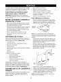
Become familiar with
the pressure washer.
illustration shown on
or damaged, call the
1-800-222-3136.
each piece before assembling
Check all contents against the
page 7. If any parts are missing
pressure washer helpline at
ASSEMBLING
WASHER
YOUR PRESSURE
Your Craftsman pressure washer was mostly
assembled at the factory. However, you will need to
perform these tasks before you can operate your
pressure washer:
•
Attach handle and hooks.
•
Attach hose reel.
•
•
Add oil to engine crankcase.
Add fuel to fuel tank.
•
Connect high pressure hose to the spray gun and
the pump.
•
Connect water supply to the pump.
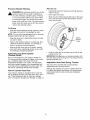
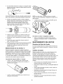
Attach
•
Handle
and Hooks
Place the handle onto the handle supports already
connected to the main unit. Make sure the holes in
the handle align with the holes on the handle
supports.
Handle
Align
Holes
Handle
Supports
NOTE: It may be necessary to move the handle
supports from side to side in order to align the handle
so it will slide over the handle supports.
•
Insert the carriage bolt through the hole on the right
side of the handle (viewing from rear of unit) and
attach the plastic knob. Tighten the knob by hand.
•
Insert one of the "L" bolts (detergent bottle hook)
through the hole on the left side of the handle
(viewing from rear of unit) and attach the plastic
knob. Tighten the knob by hand. If not installed, add
the vinyl cap to the "L" bolt.
.J
Gun Hook
So,,""
._ Detergent
Bottle Hook
•
Insert the other "L" bolt (gun hook) through the hole
just under the billboard on the right side of the
handle (viewing from rear of unit). Hold the hook in
place with a pliers and attach the Iocknut with a
7/16" wrench. If not installed, add the vinyl cap to
the "L" bolt.
NOTE: Be sure to hold the hook in place with the
pliers until tight.
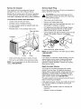
Assembling
Hose Reel
IMPORTANT: You must take the hose off the reel
when operating your pressure washer. The reel is for
storage purposes only.
•
Attach the handle to the reel with Iocknuts, flat
washers, and bolts. Please note that the bolts are
inserted with their heads inside the hose reel.
Hose reel
Handle
Locknut
* The use of multi-viscosity oils (5W-30, 10W-30, etc.)
in temperatures above 40°F (4°C) will result in higher
than normal oil consumption. When using a multiviscosity oil, check oil more frequently.
** If using SAE 30 oil in temperatures below 40°F
(4°C), it will result in hard starting and possible
engine bore damage due to inadequate lubrication.
•
•
Place pressure washer on a level surface.
Clean area around oil fill.
•
Remove oil fill cap.
•
Pour oil slowly. Fill to the point of overflowing.
• Replace oil fill cap, tighten securely.
NOTE: Check oil often during engine break-in.
Flat washer
Add Gasoline
Bolt
Secure the hose reel on the handle, at the location
shown on page 7 with Iocknuts and bolts.
_
Never
fill fuel
indoors.
fill ARNING!
fuel tank when
engine
is tank
running
or hot.Never
Do
Not smoke when filling fuel tank.
Clamp
,_
WARNING!
fill expansion.
fuel tank completely
Provide spaceNever
for fuel
Wipe awayfull.
any fuel spillage from engine and equipment
and let residue evaporate before starting.
Locknut
/
Use fresh, clean unleaded automotive gasoline and
store in approved, clean, covered containers. Use
clean fill funnels. Never use "stale" gasoline left
over from last season or gasoline stored for long
periods.
•
Clean area around fuel fill cap, remove cap.
•
Slowly add gasoline to fuel tank. Use a funnel to
prevent spillage. Fill tank to about 1.5" below top of
the filler neck to allow for fuel expansion.
Screw
Hose Clip
Bolt
•
•
Attach the spring clip with a black self tapping
screw in the hole provided on the clamp.
NOTE: There may be some hardware included with
the hose reel kit that is not used on this model.
Add Engine
_'_.
_
r-Tank
Oil
IMPORTANT: Any attempt to crank or start the engine
before it has been properly serviced with the
recommended oil may result in an engine failure.
NOTE: When adding oil to the engine crankcase, use
only high quality detergent oil rated with API service
classification SF, SG, SH, SJ or higher rated SAE 30
weight. Do Not use special additives.
•
Choose a viscosity according to the table below:
Uorl_I(
r
4
F
'C
-20
-30'
STARTING
0
-20'
TEMPERATURE
20
-10
32
_
RANGE
40
60
10
ANTICIPATED
80
20
BEFORE
100
30
NEXT
40
OIL CHANGE
•
Install fuel cap and wipe up any spilled gasoline.
Connect
Hose and Water Supply
Connect the garden hose to the water inlet. Tighten
by hand.
Inspect inlet
screen. Do
use if
to Pump
IMPORTANT: You must attach all hoses before you
start engine. Starting engine without all hoses
connected and water supplied will damage pump.
•
Uncoil high pressure hose and attach one end of
hose to the base of the spray gun. Tighten by
hand.
damaged;
if dirty.
%-.
CAUTION!
There MUST be at least ten feet of
unrestricted garden hose between the pressure
washer inlet and any flow shut off device, such as a 'Y'
shut-off connector or other convenience-type water
shut-off valve. Damage to pressure washer resulting
from disregarding this warning will not be covered by
the warranty.
•
Attach other end of high pressure hose to the high
pressure outlet on the pump. Tighten by hand.
•
Turn ON the water (open supply valve completely).
CAUTION!
Before starting the pressure
washer, be sure you are wearing adequate
eye protection.
CHECKLIST
INE
BEFORE
STARTING
Review the assembled unit to ensure you have
performed all of the following:
Check that hose reel fasteners are tight.
•
•
Before you connect your garden hose to the water
inlet, inspect the inlet screen. Clean the screen if it
contains debris or have it replaced if damaged.
DO NOT RUN THE PRESSURE WASHER IF THE
INLET SCREEN IS DAMAGED. NEVER SIPHON
INLET WATER.
Run water through garden hose for 30 seconds to
flush it of debris.
•
Check that oil has been added to proper level in
engine crankcase.
•
Add proper gasoline to fuel tank.
•
Check for properly tightened hose connections
(high pressure and water supply) and that there are
no kinks, cuts, or damage to the high pressure
hose.
•
•
Provide proper water supply (not to exceed 100°F).
Be sure to read "Safety Rules" and "Operation"
sections before using the pressure washer.
If starting unit after storage, see "Storage" section
on page 15.
•
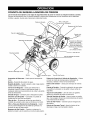
KNOW YOUR PRESSURE
WASHER
Read the owner's manual and safety rules before operating your pressure washer.
Compare the illustrations with your pressure washer to familiarize yourself with the locations of various controls
and adjustments. Save this manual for future reference.
Spray Gun
Detergent Pick-Up
Tube and Filter
High Pressure Hose
Hose Reel
Fuel Cap
Choke Lever
Fuel Valve
Throttle Control Lever
Recoil Starter
(on front of engine)
Nozzle Extension
Adjustable
Nozzle
Air Filter
Thermal Relief
Valve
Oil Fill Cap
Water Inlet
Adjustable Nozzle- Always attached to nozzle
extension. Pull back for high pressure or push forward
for low pressure; turn clockwise for narrow spray or
turn counterclockwise for fan spray.
Air Filter - Dry type filter element limits the amount of
dirt and dust that gets in the engine.
Choke Lever - Used to help start a cold engine.
Chemical Injection Siphon/Filter - Used to siphon
detergent from chemical bottle to the low pressure
water stream.
Fuel Valve -- Used to turn fuel on and off to engine.
Fuel Cap - Engine is filled with regular unleaded
gasoline here.
High Pressure Hose - Connect one end to the spray
gun and other end to the high pressure outlet.
High Pressure
hose.
Outlet - Connection for high pressure
Pump
High Pressure Outlet
Hose Reel -- Used for storing hose while unit is not in
use. Hose must be detached from unit and spray gun
before storage.
Nozzle Extension - Attach to spray gun to use
adjustable nozzle.
Oil Fill Cap - Engine is filled with oil here. See page 5
for oil recommendations and filling instructions.
Pump - Develops high water pressure.
Recoil Starter-
Used for starting the engine.
Spray gun - Controls the application of water onto
cleaning surface with trigger device. Includes safety
latch.
Thermal Relief Valve - Discharges pump water if it
becomes too hot.
Throttle Control Lever - Sets engine in starting
mode for recoil starter and stops running engine.
Water Inlet - Connection for garden hose.
HOW TO USE YOUR PRESSURE
WASHER
•
If you have any problems operating your pressure
washer, please call the pressure washer helpline at
1-800-222-3136.
To Start Your Pressure
•
Place the pressure washer in an area close
enough to an outside water source capable of
supplying water at a flow rate greater than
2.4 gallons per minute.
Check that the high pressure hose is tightly
connected to the spray gun and to the pump. See
"Assembling Your Pressure Washer" for
illustrations.
•
Make sure unit is in a level position.
•
Connect the garden hose to the water inlet on the
pressure washer pump. Turn ON the water.
CAUTION!
Do Not run the pump without the water
supply connected and turned on. You must follow this
caution or the pump will be damaged.
•
Squeeze trigger on gun to purge pump system of
air and impurities.
•
Attach nozzle extension to spray gun. Tighten by
hand.
•
•
Position the nozzle in the low pressure mode (slide
nozzle forward) and squeeze the trigger on the
spray gun to relieve pressure caused by turning
ON the water. Water will flow out of the gun in a
thin stream. Continue to hold trigger until there is a
steady stream of water and no air remains in the
system. Release the trigger.
Engage the safety latch to the spray gun trigger.
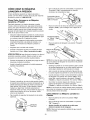
@
Fuel Valve shown in
"On" position
Washer
To start your engine-powered pressure washer for the
first time, follow these instructions step-by-step. This
starting information also applies whenever you start
the engine after you have let the pressure washer sit
idle for at least a day.
•
Rotate the fuel shut-off valve to the "On" position
(fully counter-clockwise).
Safety Latch
•
Move the throttle lever to "Fast" position.
Throttle Lever in
"Fast" Position
•
Move the choke lever to the "Choke" position.
Choke Lever "
Shown in
"Run" Position
NOTE: For a warm engine, be sure the choke lever is
in the "Run" position.
•
Grasp the unit's handle with your left hand. Pull the
starter grip lightly with your right hand until you feel
some resistance, then pull briskly.
•
Return the starter grip handle slowly. Do Not let
rope "snap back" against starter.
•
When engine starts, slowly move choke lever to
the "Run" position. If engine falters, move choke
lever to the "Choke" position, then to the "Run"
position.
•
If engine fails to start after six pulls, move choke
lever to the "Run" position. If engine fires, but does
not continue to run, move choke lever to the
"Choke" position, then to the "Run" position.
NOTE: If the recoil starter is hard to pull, it may be
necessary to squeeze the gun trigger to relieve
internal pump pressure.
How to Stop Your Pressure
Washer
•
Move throttle lever to "Stop" position.
•
Turn the fuel shut-off valve to the "Off" position
(fully clockwise).
Squeeze trigger on the spray gun to relieve
pressure in the hose.
•
NOTE: A small amount of water will squirt out when
you release the pressure.
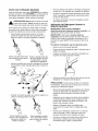
How To Use the Adjustable
Nozzle
Now that you know how to START and STOP your
pressure washer, the information in this section will tell
you how to adjust the spray pattern and apply
detergent or other cleaning chemicals.
_
CAUTION!
Never
whento
spraying. Never
put adjust
hands spray
in frontpattern
of nozzle
adjust spray pattern.
On the end of your spray gun is an adjustable nozzle
that you can use to adjust the spray pattern and the
spray pressure.
•
Slide the nozzle forward for low pressure spray;
slide it backward for high pressure spray.
•
For most effective cleaning, keep the spray nozzle
between 8 to 24 inches away from cleaning
surface.
•
If you get the spray nozzle too close, especially
using high pressure mode, you may damage the
surface being cleaned.
•
Do Not get closer than 8 inches when cleaning
tires.
Applying
Nozzle
Detergent
with the Adjustable
IMPORTANT: Use chemicals designed specifically
for pressure washers, Household detergents could
damage the pump.
IMPORTANT: You MUST attach all hoses before you
start the engine. Starting the engine without all the
hoses connected and without the water turned ON will
damage the pump.
To apply detergent, follow these steps:
Slide nozzle backward for
high pressure mode.
•
•
Review the use of the adjustable nozzle.
•
Prepare detergent solution as required by the job.
•
Hang the detergent solution container on the
lowest hook attached to the handle.
•
Place the filter end of the detergent siphoning tube
into the detergent container.
Slide nozzle forward for
low pressure mode and
detergent application.
Point the nozzle towards a hard surface, disengage
the safety latch, and press the trigger to test the
pattern.
CAUTION! When inserting the filter into the detergent
container, route the tube so as to keep it from
inadvertently contacting the hot muffler.
•
Slide the adjustable nozzle forward to low pressure
mode. Detergent cannot be applied with the nozzle
in high pressure position.
•
Make sure the garden hose is connected to the
water inlet. Check that the high pressure hose is
connected to the spray gun and the pump. Start
the engine.
•
Apply detergent to a dry surface, starting from the
bottom and working up.
•
Allow the detergent to "soak in" for 3-5 minutes
before rinsing. Reapply as needed to keep the
surface wet.
•
For washing, start at lower portion of area to be
washed and work upward, using long, even,
overlapping strokes.
Rotating the nozzle adjusts the spray pattern from
a narrow pattern to a fan pattern.
Twist nozzle counterclockwise for fan pattern.
Twist nozzle clockwise for
narrow spray pattern.
Pressure
Washer
After each use:
Rinsing
•
WARNING!
Be extremely careful if you use the
pressure washer from a ladder, scaffolding or
any other relatively unstable location. Pressure
in a running washer builds as you climb. When
you press the trigger, the recoil from the initial
spray could cause you to fall. The high pressure
spray could also cause you to fall if you are too
close to the cleaning surface.
•
•
Disconnect hose from spray gun and high pressure
outlet on pump.
Drain water from hose.
Slide one end of the hose into the hole on the hose
reel. Turn the hose reel with the handle to coil the
hose onto the reel.
For Rinsing:
•
Slide the nozzle backward to high pressure, press
the trigger and wait for the detergent to clear.
NOTE: You can also stop detergent flow by removing
detergent siphoning tube from container.
•
Keep the spray gun a safe distance from the area
you plan to spray.
•
Apply a high pressure spray to a small area, then
check the surface for damage. If no damage is
found, it is okay to continue cleaning.
•
Start at the top of the area to be rinsed, working
down with same overlapping strokes as you used
for washing and applying detergent.
Automatic
Cool
Spring
Tension
Knob
•
Down System
(Thermal Relief)
IMPORTANT: Do Not use your pressure washer with
the hose coiled onto the hose reel. The hose reel is for
storage purposes only.
If you run the engine on your pressure washer for
3-5 minutes without pressing the trigger on the spray
gun, circulating water in the pump can reach
temperatures between 125°-155°F. The automatic
cool down system engages at this temperature and
cools the pump by discharging the warm water onto
the ground, preventing internal pump damage.
Adjustable
Hose Reel Spring Tension
The hose reel is provided with a spring tension
adjustment knob, as shown above.
Although the operator can loosen or tighten the knob
to achieve the desired reel tension, the manufacturer
recommends that the knob be fully hand tightened
(clockwise).
How to Use the Hose Reel
Your pressure washer is equipped with a
that is designed to store your hose when
use. These instructions are for short term
only. For long term storage see "Storage"
Push the other end of the hose into the clip on the
handle of your unit.
hose reel
unit is not in
storage
on page 15.
10
OWNER'S
RESPONSIBILITIES
Follow the hourly or calendar intervals, whichever occurs first.
More frequent service is required when operating in adverse conditions noted below.
MAINTENANCE SCHEDULE
FILL IN DATES AS YOU COMPLETE
REGULAR SERVICE
HOURLY OPERATING
INTERVAL
Before
Each Use
MAINTENANCETASK
PRESSURE WASHER
Check/clean water inlet screen
Check high pressure hose
Check detergent hose
Check spray gun and assembly for
leaks
Every 100
Hours or
Yearly
X1
X
X
X
X
Purge pump of air and contaminants
Prepare pump for storage below 32°F
ENGINE
Check oil level
Change
Service
Service
Service
Prepare
Every 50
Hours or
Yearly
SERVICE DATES
See "Storage"on page 15.
x .....
x_
engine oil
air cleaner
spark plug
spark arrester
for storage
x3
x
};
}
x
If unit is to remain
idle for
longer than 30 days.
1
Clean if clogged. Replace if perforated
2
Change oil after the first (5) operating hours and every 50 hours or every year, whichever
Change sooner when operating
or torn.
occurs first, thereafter.
under dirty or dusty conditions.
Replace more often under dirty or dusty conditions.
PRODUCT
Pressure
SPECIFICATIONS
Washer
2400 PSI
2.2 GPM
Use as directed
Not to Exceed 100°F
94 Ibs.
Some adjustments will need to be made periodically to
properly maintain your pressure washer.
Specifications
Rated Horsepower ...........
Spark Plug Type:
Resistor ...............
Long Life Platinum .......
Set Gap To: ..............
Gasoline Capacity ............
Oil
Above 40°F ..........
0°F - 40°F ...........
RECOMMENDATIONS
The pressure washers warranty does not cover items
that have been subjected to operator abuse or
negligence. To receive full value from the warranty,
the operator must maintain pressure washer as
instructed in this manual including proper storage as
detailed in "Storage" on page 15.
Specifications
Pressure ...................
Flow Rate ..................
Chemical Mix ...............
Water Supply Temperature .....
Shipping Weight .............
Engine
GENERAL
All service and adjustments should be made at least
once each season. Follow the requirements in the
"Maintenance Schedule" chart above.
6.5 liP
Champion RC12YC
NOTE: Once a year you should clean or replace the
spark plug and replace the air filter. A new spark plug
and clean air filter assure proper fuel-air mixture and
help your engine run better and last longer.
Champion RC12PYP
0.020 inches (0.50 mm)
3.0 Quarts
SAE 30
SAE 5W-30 or 10W-30
11
BEFORE
EACH USE
.
•
Check engine oil level.
•
Check water inlet screen for damage.
•
Check high pressure hose for leaks.
•
Check chemical filters for damage.
•
Check spray gun and nozzle extension assembly
for leaks.
•
Purge pump of air and contaminants.
PRESSURE WASHER
MAINTENANCE
Place the in-line filter screen into the threaded end
of the nozzle extension. Direction does not matter.
Push the screen in with the eraser end of a pencil
until it rests flat at the bottom of the opening. Take
care to not bend the screen.
4.
Place the o-ring into the recess. Push the o-ring
snugly against the in-line filter screen.
5.
Assemble the nozzle extension to the spray gun,
as described earlier in this manual.
Purge Pump of Air and Contaminants
To remove air from the pump, follow these steps:
Check and Clean Inlet Screen
•
Examine garden hose inlet screen. Clean if it is
clogged or replace if it is torn.
Set up the pressure washer as described in the
ASSEMBLY section and connect the water supply.
•
Pull the trigger on the spray gun and hold until a
steady stream of water appears.
Check
High Pressure
Hose
To remove contaminants from the pump, follow these
steps:
High pressure hoses can develop leaks from wear,
kinking, or abuse. Inspect hose before each use.
Check for cuts, leaks, abrasions, bulging of cover, or
damage or movement of couplings. If any of these
conditions exist, replace hose immediately.
_
ANGER!withNever
a high pressure
hose.
Replace
hose repair
that exceeds
the maximum
pressure rating of your pressure washer.
Check Spray Gun and Nozzle
In-Line
Set up the pressure washer as described in the
ASSEMBLY section, and connect the water supply.
•
Remove the nozzle extension from the spray gun.
•
Start the engine according to instructions in
OPERATION section.
•
•
Pull the trigger on the spray gun and hold.
When the water supply is steady and constant,
engage the safety latch and refasten the nozzle
extension.
Extension
Examine hose connection to spray gun and make sure
it is secure. Test trigger by pressing it and making
sure it springs back into place when you release it.
Engage safety latch and test trigger. You should not
be able to press trigger. Replace spray gun
immediately if it fails any of these tests.
Check
•
Nozzle
A pulsing sensation felt while squeezing the spray gun
trigger may be caused by excessive pump pressure.
The principal cause of excessive pump pressure is a
nozzle clogged or restricted with foreign materials,
such as dirt, etc. To correct the problem, immediately
clean the nozzle using the tools included with your
pressure washer and follow these instructions:
1. Shut off the engine and turn off the water supply.
Filter
Refer to the illustration and service the in-line filter if it
becomes clogged, as follows:
2.
In-line Filter
Nozzle
O-ring
.
.
Maintenance
Detach spray gun and nozzle extension from high
pressure hose. Detach nozzle extension from
spray gun and remove o-ring and screen from
nozzle extension. Flush the screen, spray gun,
and nozzle extension with clean water to clear
debris.
Detach the nozzle extension from the spray gun.
Twist the nozzle clockwise to the stream position.
Using the supplied 2mm (5/64) allen wrench,
remove the nozzle from the end of the nozzle
extension.
\
.
If the screen is damaged, the o-ring kit contains a
replacement in-line filter screen and an o-ring. If
undamaged, reuse screen.
4.
12
Remove the in-line filter from the other end of the
nozzle extension.
Use the wire included in the kit (or a small paper
clip) to free any foreign material clogging or
restricting the nozzle.
•
1 o-ring, yellow, (p/n B2264) for the end of the
high pressure hose.
Insert wire into nozzle and turn back
and forth to clear obstruction.
5.
Using a garden hose, remove additional debris by
back flushing water through the nozzle extension.
Back flush between 30 to 60 seconds. Turn the
adjustable nozzle extension to stream spray and
move the nozzle from low to high while flushing.
NOTE: The above two o-rings are close in size.
Please match carefully to assure proper o-ring usage.
•
6.
1 water inlet screen (p/n B2384) for the garden
hose connector.
Reinstall the nozzle and in-line filter into the
nozzle extension. Do Not overtighten the nozzle
with the allen wrench.
7.
Reconnect the nozzle extension to the spray gun.
8.
Reconnect the water supply, turn on the water,
and start the engine.
9.
To remove a worn or damaged O-Ring:
•
Test the pressure washer by operating with nozzle
in the high and in the low positions.
ENGINE MAINTENANCE
O-RING MAINTENANCE
Checking
Your pressure washer uses o-rings to keep hose and
spray gun connections tight and leak-free. Through
the normal operation of your unit, these o-rings may
become worn or damaged.
Oil Level
Oil level should be checked prior to each use or at
least every 5 hours of operation. Keep oil level
maintained.
Provided with your pressure washer is an O-Ring
Maintenance Kit which includes replacement o-rings,
rubber washer and water inlet filter. Refer to the
instruction sheet provided in the kit to service your
unit's o-rings. Note that not all of the parts in the kit
will be used on your unit.
Changing
Oil
Change engine oil after the first 5 hours and every
50 hours thereafter. If you are using your pressure
washer under extremely dirty or dusty conditions, or in
extremely hot weather, change oil more often.
Change oil while engine is still warm from running, as
follows:
Parts in the O-Ring Kit Include:
•
Use a small flathead screwdriver to get underneath
the o-ring and pry it off.
1 o-ring, red, (p/n B2726) for the end of the spray
gun connection between spray gun and nozzle
extension.
O
13
•
Drain fuel tank by running pressure washer until
fuel tank is empty.
•
Disconnect spark plug wire and keep it away from
the spark plug.
•
Remove oil drain plug and drain oil into appropriate
receptacle.
•
Reinstall drain plug. Remove oil fill cap.
•
Fill to point of overflowing at oil fill cap with
recommended oil.
•
Reinstall oil fill plug and tighten securely.
•
Wipe up any remaining oil.
•
Reconnect spark plug wire to the spark plug.
Service
Air Cleaner
Service
Your engine will not run properly and may be
damaged if you run it with a dirty air cleaner.
Spark
Plug
Service the spark plug every 100 hours of operation or
yearly, whichever occurs first.
Replace the air cleaner every 100 hours of operation
or once each year, whichever comes first. Replace
more often if operating under dirty or dusty conditions.
,_
To service the air cleaner, follow these steps:
•
Loosen screw and tilt cover down.
•
Carefully remove cartridge assembly.
•
To clean cartridge, gently tap pleated paper side
on a flat surface.
•
Reinstall clean or new cartridge inside cover.
CAUTION!
Disconnect
from
spark
plug and
keep wirespark
away plug
fromwire
spark
plug
while servicing engine.
•
Clean area around spark plug.
•
Remove and inspect spark plug.
•
Replace spark plug if the electrodes are worn, or if
the insulator is cracked or chipped.
•
For replacement use either the standard resistor
spark plug, Champion RC12YC or the long life
platinum spark plug, Champion RC12PYP.
•
Check electrode gap with wire feeler gauge and set
gap at 0.020 inches (0.50mm), if necessary.
•
Install spark plug, tighten securely.
Tabs and Slots
Cartridge
Base
Screw
NOTE: You can purchase a new spark plug by calling
1-800-366-PART.
Carburetor
Cover
•
Insert cover's tabs into slots in bottom of base.
•
Tilt cover up and tighten screw securely to base.
If you think your carburetor needs adjusting, see your
nearest Sears service center. Engine performance
may be affected at attitudes above 7000 feet. For
operation at higher elevations, contact your nearest
Sears service center.
NOTE: You can purchase new air filter elements by
calling 1-800-366-PART.
Spark Arrester
Service
Your engine is not factory-equipped with a spark
arrester. In some areas, it is illegal to operate an
engine without a spark arrester. Check local laws and
regulations. A spark arrester is available from your
nearest Sears service center. If you need to order a
spark arrester, please call 1-800-366-PART.
The spark arrester must be serviced every 50 hours to
keep it functioning as designed.
If the engine has been running, the muffler will be very
hot. Allow the muffler to cool before servicing the
spark arrester.
14
•
Remove spark arrester screen for cleaning and
inspection.
•
Replace if screen is damaged.
AFTER EACH USE
•
Water should not remain in the unit for long periods of
time. Sediments or minerals can deposit on pump
parts and "freeze" pump action. Follow these
procedures after every use:
_
•
Flush detergent siphoning tube by placing the filter
into a pail of clean water while running pressure
washer in low pressure mode (adjustable nozzle in
the forward position). Flush for one to two minutes.
•
Shut off engine, let it cool, then remove garden and
high pressure hoses.
•
Disconnect spark plug wire from spark plug.
•
Empty the pump of all liquids by pulling recoil
handle about 6 times. This should remove most of
the liquid in the pump.
•
If storing for more than 30 days see "Long Term
Storage" on next page.
•
Disconnect hose from spray gun and high pressure
outlet on pump. Drain water from hose, gun, and
nozzle extension. Use a rag to wipe off the hose.
•
Coil the high pressure hose and inspect it for
damage. Cuts in the hose or fraying could result in
leaks and loss of pressure. Should any damage be
found, replace the hose. Do Not attempt to repair a
damaged hose. Replace the hose with the genuine
Craftsman part.
Slide one end of the hose into the hole on the hose
reel. Turn the hose reel with the handle to coil the
hose onto the reel. Push the other end of the hose
into the clip on the side of the unit.
•
•
Store unit in a clean, dry area.
Never store
the engine poorly
with fuel in
theARNING!
gas tank indoors
or in enclosed,
ventilated areas where fumes may reach an
open flame, a spark, or standing gas pilot.
WINTER
STORAGE
CAUTION! You must protect your unit from freezing
temperatures. Failure to do so will permanently
damage your pump and render your unit inoperable.
Freeze damage is not covered under warranty.
To protect the unit from freezing temperatures:
Reconnect spark plug wire to spark plug.
15
•
Flush detergent siphoning tube by placing the filter
into a pail of clean water while running pressure
washer in low pressure mode (adjustable nozzle in
the forward position). Flush for one to two minutes.
•
Empty the pump of all pumped liquids by pulling
recoil handle about 6 times. This should remove
most of the liquid in the pump.
•
Use PumpSaver, available at Sears retail item
number 74403, to treat pump. This prevents freeze
damage and lubricates pistons and seals.
•
If pump saver is not available, connect a 3-foot
section of garden hose to the water inlet adapter.
Pour RV-antifreeze (antifreeze without alcohol) into
the hose. Pull the recoil handle twice. Disconnect
3-foot hose.
LONG TERM STORAGE
Oil Cylinder
If you do not plan to use the pressure washer for more
than 30 days, you must prepare the engine and pump
for long term storage.
•
Remove spark plug. Squirt about 1 tablespoon of
clean engine oil into the cylinder. Cover spark plug
hole with rag. Pull recoil handle slowly to distribute
oil. Avoid spray from spark plug hole.
•
Install spark plug. Do Not connect spark plug wire.
It is important to prevent gum deposits from forming in
essential fuel system parts such as the carburetor, fuel
filter, fuel hose or tank during storage. Also,
experience indicates that alcohol-blended fuels (called
gasohol, ethanol or methanol) can attract moisture,
which leads to separation and formation of acids
during storage. Acidic gas can damage the fuel
system of an engine while in storage.
Protect
Protect
_
Fuel Additive:
•
Connect water supply to pump inlet and turn it ON.
NOTE: If pump saver is not available,
antifreeze (non-alcohol) into the pump
solution into a 3-foot section of garden
connected to inlet adapter and pulling
twice.
•
Run the engine outdoors for 10 minutes to be sure
that treated gasoline has replaced the untreated
gasoline in the carburetor.
If fuel additive is not used, remove all fuel from tank
and run engine until it stops from lack of fuel.
Change
CAUTION!on the
Read
and saver
follow can
all cautions
and
warnings
pump
label. Always
wear eye protection when using pump saver.
To use pump saver, make sure the pressure washer is
turned off and disconnected from supply water. Read
and follow all instructions and warnings given on the
pump saver container.
If adding a fuel additive, fill the fuel tank with fresh
gasoline. If only partially filled, air in the tank will
promote fuel deterioration during storage. Engine and
fuel can be stored up to 24 months with additive.
Add fuel additive following manufacturer's
instructions.
Pump
To protect the pump from damage caused by mineral
deposits or freezing, use the pump saver (Sears item
number 74403).
Fuel System
•
Bore
draw RV
by pouring the
hose
recoil handle
NOTE: PumpSaver will drip from pump after treatment
and will stain wood and concrete.
OTHER
Oil
While engine is still warm, drain oil from crankcase.
Refill with recommended grade. See "Changing Oil" on
page 13.
•
Do Not store gasoline from one season to another.
•
If possible, store your unit indoors and cover it to
give protection from dust and dirt. BE SURE TO
EMPTY THE FUEL TANK.
IMPORTANT: Never cover your pressure washer
while engine and exhaust area are warm.
16
Problem
Cause
Pump has following
problems: failure to produce
pressure, erratic pressure,
chattering, loss of pressure,
low water volume.
Detergent fails to mix with
spray.
Engine runs good at no-load
but "bogs" when load is
added.
Nozzle in low pressure mode.
1.
2.
3.
4.
5.
Water inlet is blocked.
Inadequate water supply.
Inlet hose is kinked or leaking.
Clogged inlet hose strainer.
2.
3.
4.
5.
Water supply is over 100°F.
High pressure hose is blocked or
leaks.
8. Gun leaks.
9. Nozzle is obstructed.
10. Pump is faulty.
6.
7.
1.
1.
6.
7.
2.
Detergent siphoning tube is not
submerged.
Chemical filter is clogged.
3.
Dirty in-line filter.
4.
Nozzle is in high pressure mode.
Engine speed is too slow.
1.
2.
3.
4.
Engine will not start; or
starts and runs rough.
Correction
1.
5.
6.
7.
Dirty air cleaner.
Out of gasoline.
Stale gasoline.
Spark plug wire not connected to
spark plug.
Bad spark plug.
Water in gasoline.
Overchoking.
Excessively rich fuel mixture.
Intake valve stuck open or
closed.
10. Engine has lost compression.
Out of gasoline.
.
9.
Engine shuts down during
operation.
Engine lacks power.
Engine "hunts"
or falters.
Pull nozzle backward for high
pressure mode.
Clear inlet.
Provide adequate water flow.
Straighten inlet hose, patch leak.
Check and clean inlet hose
strainer.
Provide cooler water supply.
Clear blocks in outlet hose.
8. Replace gun.
9. Clean nozzle.
10. Contact Sears service facility.
Insert detergent siphoning tube
into detergent.
2. Clean or replace filter/detergent
siphoning tube.
3. See "Check In-Line Filter" on
page 12.
4. Push nozzle forward for low
pressure mode.
Move throttle control to FAST
position. If engine still "bogs down",
contact Sears service facility.
1.
2.
3.
4.
.
6.
7.
8.
9.
Clean or replace air cleaner.
Fill fuel tank.
Drain gas tank; fill with fresh fuel.
Connect wire to spark plug.
Replace spark plug.
Drain gas tank; fill with fresh fuel.
Open choke fully and crank
engine.
Contact Sears service facility.
Contact Sears service facility.
10. Contact Sears service facility.
Fill fuel tank.
Dirty air filter.
Replace air filter.
Choke is opened too soon.
Move choke to halfway position until
engine runs smoothly.
17
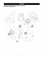
CRAFTSMAN
2400 PSI Pressure
Main Unit m Exploded View
Washer
580.767302
3O
30
28
28
97
\
3O
90
24
32
3 J
\
\
\
_9
/
33
25
35
36
\
\_
30
_
39
4\\
\\
\_
37
25
38
18
_
_/
\--29
CRAFTSMAN
2400 PSI Pressure
Main Unit m Parts List
Item
1
2
3
5
6
7
8
9
10
11
12
13
14
15
16
17
18
19
20
21
22
23
24
25
26
27
28
29
30
31
or
32
33
34
35
36
37
38
39
900
Washer
580.767302
Part #
Qty. Description
E190506GS
1 BASE
CB1982GS
1 BUMPER
188194GS
2 BLIND RIVET
191413GS
2 VIBE MOUNT, with Washer
190537GS
1 CAP, Vinyl, Black
B2150GS
1 HOOK, Gun
B2516GS
1 CAP, Vinyl, Black
B2043GS
7 BOLT, Carriage
30809GS
1 GROMMET, Rubber
190821GS
1 MANUAL
CB1983AGS
1 HANDLE
188258GS
1 DECALS/BILLBOARD
190862GS
1 KIT, Maintenance
99583GS
8 NUT, Flange Lock
C190258GS
2 SUPPORT, Handle
23139DGS
1 KEY
48031BGS
2 CLAMP, Hose Band
21783GS
1 VALVE, Thermal Relief
B3107GS
1 HOSE, Thermal Drain
23707GS
4 CAPSCREW, Socket Head
92479GS
4 WASHER, Conical Ribbed
B5689GS
1 HOSE, High Pressure
189943GS
1 ASSY, Complete Pump (see pages 20-21)
67989GS
8 NUT, Flange Serrated
21217GS
4 MOUNT, Rubber Shock
B1232GS
1 CLAMP, Hose
186113GS
1 KIT, Hardware Hose Reel
186114GS
1 REEL, Hose
191433GS
1 KIT, HNDL, FSTNNG, SRV
B4966GS
189311GS
2 ASSY, Tire & Wheel
190147GS
2 PUSHNUT
B3263GS
1 GUN, High Pressure
94804GS
1 NOZZLE, White Replacement
97566GS
1 TAG, Nozzle Instructions
B3335AGS
1 WAND, Nozzle Hi/Lo
97837GS
1 O-RING, Hi Pressure
B4224GS
1 SCREEN, Gun Inlet
AB3061BGS
1 OIL
NSP
1 ENGINE
B5747GS
1 ASSY, Complete Hose Reel (Includes Items 28 & 29)
Optional Accessories
7175187GS
7175197GS
7175199GS
7175115GS
7175116GS
7174400GS
7174401GS
7174402GS
7174403GS
7174300GS
7174301GS
7174302GS
7174303GS
7174307GS
Not Illustrated
Garden Hose Quick Connect
Accessory Quick Connect
Rotating Brush Kit
25' Replacement Hose
O Ring Repair Kit
Turbo Nozzle
25' Extension Hose
Hose Reel
Pump Saver
House Wash Concentrate (makes 4 gallons)
Deck Wash Concentrate (makes 2 gallons)
Vehicle / Boat Wash Concentrate (makes 4 gallons)
Degreaser Concentrate (makes 4 gallons)
Mold/Mildew Concentrate (makes 2 gallons)
19
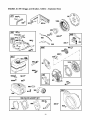
CRAFTSMAN
2400 PSI Pressure
Pump m Exploded View
Washer
580.767302
L
8
F
2O
CRAFTSMAN
2400 PSI Pressure
Pump m Parts List
Item
1
3
9
Part #
190568GS
190569GS
190671GS
Qty.
1
1
1
19
23
28
29
30
34
190571GS
190573GS
190673GS
190575GS
190576GS
190577GS
1
1
1
1
1
1
45
46
47
62
68
69
76
77
A
190578GS
190579GS
190580GS
190581GS
190582GS
190584GS
21783GS
190585GS
190672GS
1
1
1
1
1
1
1
1
0
10
11
12
13
......
......
......
......
2
1
1
1
15
16
17
70
74
77
B
8
20
......
......
......
......
......
......
190670GS
......
......
1
1
1
3
5
1
0
1
1
21
22
D
16
70
71
72
73
74
77
E
24
25
26
27
44
74
......
......
190590GS
......
......
......
......
......
......
......
190591GS
......
......
......
......
......
......
1
1
0
1
3
3
3
3
5
1
0
3
3
6
4
4
5
Washer
580.767302
Description
SEAL
RETAINER RING
ENGINE ADAPTER &
BEARING
CAP, Oil
PISTON HOUSING
MANIFOLD
O-RING
SCREW, Venturi
CONNECTION, Chemical
Inlet
PIN
VALVE, Seat Plate Brass
VALVE, Seat Stainless
CAP
BALL, Stainless Steal
O-RING
THERMAL RELIEF
OIL BOTTLE
KIT, WOBBLE PLATE
BEARING
FLAT BEARING DISC
FLAT BEARING DISC
ROLLER BEARING
WOBBLE PLATE, Sleeve &
Cap
BEARING DISC
O-RING
ROLLER BEARING
SCREW
SCREW
OIL BOTTLE
KIT, WATER INLET
WASHER
GARDEN HOSE w/FINGER
GRIP
NIPPLE, Garden Hose
WASHER w/ FILTER
KIT, PISTON
O-RING
SCREW
SPRING
PISTON, Stainless Steel
SPRING PLATE
SCREW
OIL BOTTLE
KIT, CHECK VALVES
O-RING
O-RING
ASSY., Check Valve
O-RING
SCREW
SCREW
Item
F
37
38
39
40
41
42
43
G
31
32
33
34
35
36
H
48
49
50
51
52
53
54
55
56
57
58
59
60
61
J
78
79
80
81
K
18
61
63
64
65
66
67
74
L
44
74
75
M
76
77
78
Part #
190592GS
......
......
......
......
......
......
......
190593GS
......
......
......
......
......
......
190594GS
......
......
......
......
......
......
......
......
......
......
......
......
......
......
189971GS
......
......
......
......
190595GS
......
......
......
......
......
......
......
......
190596GS
......
......
......
190669GS
......
......
......
Qty. Description
0 KIT, INLET CHECK
1 VALVE, Non-Return
1 SPRING
1 INJECTION NOZZLE
1 O-RING
1 O-RING
1 INJECTION NIPPLE
1 O-RING
0 KIT, CHEMICAL INJECTION
1 SPRING
1 BALL
1 O-RING
1 CONNECTION, Chemical Inlet
1 O-RING
1 SCREW, Fixing
0 KIT, UNLOADER
1 BACK RING
1 O-RING
1 VALVE, By Pass, Brass
1 PISTON
1 SPRING, Easy Start
1 PISTON, Body
1 RING, Back
1 SPACER
1 SPRING, Regulation Press
1 NUT, Regulation Press
1 NUT
1 O-RING
1 O-RING
1 O-RING
0 KIT, CHEMICAL HOSE
1 O-RING
1 TUBE, Inlet Support
1 TUBE, Chemical
1 FILTER
0 KIT, SEAL SET
3 O-RING
1 O-RING
3 SEAL
3 PILOT SPACER, Brass
3 O-RING
3 WASHER
3 SEAL, H.P
5 SCREW
0 KIT, HEAD BRASS
4 SCREW
5 SCREW
1 HEAD, Pump
0 KIT, BREATHER TUBE
1 VENT VALVE, Oil Cap
1 EXTENTION, Oil
1 WASHER
NOTE: Item letters A - M are service kits and include
all parts shown within the box.
21
ENGINE,
6.5 HP, Briggs
and Stratton,
120412 - Exploded
View
51
3oo
307
24
22o_
718 _
415
_'
291
22
21
32_
3_
* REQUIRES SPECIAL TOOLS
TO INSTALL. SEE REPAIR
INSTRUCTION MANUAL.
746_42
_
32A_
22
ENGINE,
6.5 HP, Briggs
and Stratton,
120412 - Exploded
[
1341- - _
I
I
View
%
365
Q
I
I
633 Q
633AG
I
615_
I
I
1__
92'
I
186_
I
I
I
137_
I
127
108
,_L__t_
276_
276©
_?*
51//_
1221 _
5__
977 CARBURETOR
13'
276_
358 ENGINE
J
GASKET
_
GASKET
SET
971
,_
425
16_
SET
993 _
1022_
601
883_
23
ENGINE,
6.5 HP, Briggs
and Stratton,
120412 - Exploded
View
23
562_
1005
281
2221
663_
427_
851
597_
456_
J
I
J
689_
J
I
I
I
. j
1210
1211
2o9_
958(_
836A_
190
836 _
1095 VALVE GASKET
SET
305_
65A_
10
51
24
ENGINE,
Item
1
3
5
7
11
12
13
15
16
18
20
21
22
23
24
25
26
27
28
29
30
32
32A
33
34
35
36
40
45
46
51
55
58
59
60
65
65A
95
97
98
104
108
109
117
121
122
125
127
130
133
134
137
146
155
161
163
186
187
187A
188
189
190
209
209A
219
220
222
227
238
271
276
281
6.5 HP, Briggs
Part #
693811
299819
693643
695166
692600
692549
691137
691686
693887
693204
692550
281658
692551
692987
222698
690021
694167
694168
694169
499631
692785
692786
692787
691866
499423
499424
692562
691664
695759
499642
499641
691304
691304
692194
690977
693404
692555
691422
693389
805957
715257
690837
692608
691636
690024
398185
691242
691182
690023
694176
690048
695157
693749
694174
694468
691181
398187
398188
693981
690979
695882
692579
272948
692317
691050
692601
690877
694543
692127
692571
691278
693578
691724
694253
692573
691300
694256
271716
694252
and Stratton,
120412 - Parts List
Description
Cylinder Assembly
§Oil Seal (Magneto Side)
Cylinder Head
§+Cylinder Head Gasket
Breather Tube
§Crankcase Gasket
Screw (Cylinder Head)
Oil Drain Plug
Crankshaft
Cover-Crankcase
§Oil Seal (PTO Side)
Oil Fill Cap
Screw (Crankcase Cover)
Flywheel
Flywheel Key
Piston Assembly (Standard)
Piston Assembly (.010 O/S)
Piston Assembly (.020 O/S)
Piston Assembly (.030 O/S)
Ring Set (Standard)
Ring Set (.010 O/S)
Ring Set (.020 O/S)
Ring Set (.030 O/S)
Piston Pin Lock
Piston Pin
Connecting Rod
Connecting Rod Dipper
Screw (Connecting Rod)
Screw (Connecting Rod)
Exhaust Valve
Intake Valve
Valve Spring (Intake)
Valve Spring (Exhaust)
Valve Retainer
Valve Tappet
Camshaft
§+:l:1.1ntake Gasket (2 Required)
Rewind Starter Housing
Rope-Starter
Grip Insert
Starter Rope Grip
Screw (Rewind Starter)
Screw (Rewind Starter)
Screw (Throttle Valve)
Throttle Shaft
Idle Speed Kit
:l:Float Hinge Pin
Choke Valve
Choke Shaft
Main Jet (Standard)
Main Jet (High Altitude)
Carburetor Overhaul Kit
:l:Carburetor Spacer
Carburetor
:l:Welch Plug
Throttle Valve
Carburetor Float
:l:Needle Valve
:l:1.Float Bowl Gasket
Timing Key
Cylinder Head Plate
Air Cleaner Base
§:l:1.Air Cleaner Gasket
Hose Connector
Fuel Line (Cut to Length)
Fuel Line (Molded)
Screw (Control Bracket)
Rocker Arm Ball
Screw (Fuel Tank)
Governor Spring
Governor Spring
Governor Gear
Washer (Governor Gear)
Control Bracket
Governor Control Lever
Valve Cap
Control Lever
:l:1.Sealing Washer
Control Panel
Item
300
304
305
306
307
332
333
334
337
356
358
365
415
425
427
445
455
456
459
504
505
552
562
592
597
601
608
613
615
616
619
621
632
633
633A
635
663
668
689
692
718
741
742
746
773
830
832
836
836A
851
868
883
914
914A
957
958
968
971
972
975
977
993
1005
1022
1023
1026
1029
1034
1095
1070
1210
1211
§Included
:l: Included
1 Included
+ Included
25
Part #
693593
693621
690960
693610
690345
690662
692605
691061
696202
692390
695155
692568
693463
692583
694255
491588
692591
692299
281505
694254
691251
692346
691112
690800
691696
95162
693394
691665
692576
692547
691108
692310
693408
693867
691321
805529
694593
694257
691855
690572
690959
692565
692564
692566
694258
694544
693583
690661
693624
493880
692044
691893
692198
692557
694261
692586
692584
690370
694260
493640
695156
694088
692592
691890
499924
693517
691230
691343
695289
692590
498144
498144
Description
Muffler-Exhaust
Housing-Blower
Screw (Blower Housing)
Shield-Cylinder
Screw (Cylinder Shield)
Nut (Flywheel)
Armature-Magneto
Screw (Magneto Armature)
Sparkplug
Stop Wire
Engine Gasket Set
Screw (Carburetor)
Plug
Screw (Air Cleaner Cover)
Nut (Control Bracket)
Filter-A/C Cartridge
Cup-Flywheel
Plate-Pawl Friction
PawI-Ratchet
Friction Washer Set
Nut (Governor Control Lever)
Bushing-Governor Crank
Bolt (Governor Control Lever)
Nut (Rewind Starter)
Screw (Pawl Friction Plate)
Clamp-Hose
Starter-Rewind
Screw (Muffler)
Retainer-Governor Shaft
Crank-Governor
Screw (Cylinder Head Plate)
Switch-Stop
Spring/Link -Mechanical Governor
:l:1.Choke/Throttle Shaft Seal
:l:1.Choke/Throttle Shaft Seal
Boot-Spark Plug
Screw (Control Panel)
Spacer
Spring-Friction
Spring-Detent
Pin-Locating
Gear-Timing
Ring-Retaining
Gear-Idler
Washer (Control Bracket)
Stud (Rocker Arm)
Guard-Muffler
Screw (Muffler Guard)
Screw (Muffler Guard)
Sparkplug Terminal
§+Seal-Valve
§Gasket-Exhaust
Screw (Rocker Cover 7/16" Long)
Screw (Rocker Cover 3/8" Long)
Fuel Tank Cap
Fuel Shutoff Valve
Air Cleaner Cover
Screw (Air Cleaner Base)
Fuel Tank
Bowl-Float
Carburetor Gasket Set
§+Cylinder Head Plate Gasket
Fan-Flywheel
§+Gasket-Rocker Cover
Cover-Rocker
Rod-Push
Rocker Arm
Guide-Push Rod
Set-Valve Gasket
Screw (Flywheel)
Pulley/Spring Assembly (Pulley)
Pulley/Spring Assembly (Spring)
in Engine Gasket Set, Ref Number 358.
in Carburetor Overhaul Kit, Ref Number 121.
in Carburetor Gasket Set, Ref Number 977.
in Value Gasket Set, Ref Number 1033.
Your Warranty
If you have any questions regarding your warranty rights
and responsibilities, your should contact your nearest
authorized service center or call Sears at
1-800-473-7247.
Rights and Obligations
The California Air Resources Board ("CARB") and Sears
Roebuck and Co., USA, are pleased to explain the Emission
Control System Warranty on your model year 2000 and later
small off-road engine (engine). In California, new engines
must be designed, built and equipped to meet the State's
stringent anti-smog standards. Sears must warrant the
emission control system on your engine for the periods of
time listed below provided there has been no abuse, neglect,
or improper maintenance of your engine.
Warranty
Your emission control system includes parts such as the
carburetor and the ignition system.
Where a warrantable condition exists, Sears will repair your
engine at no cost to you. Expenses covered under warranty
include diagnosis, parts, and labor.
Manufacturer's
Warranty
Diagnosis
The owner shall not be charged for diagnostic labor which
leads to the determination that the warranted part is
defective if the diagnostic work is performed at an approved
Sears service center.
Coverage
The model year 2000 and later engines are warranted for
two years. If any emission related part on your engine (as
listed below) is defective, the part will be repaired or
replaced by Sears.
Owner's
Warranty
Consequential
Responsibilities
WHAT IS NOT COVERED
All failures caused by abuse, neglect, or improper
maintenance are not covered.
Add-on
If you have any questions regarding your warranty rights and
responsibilities, you should contact your nearest authorized
service center or call Sears at 1-800-473-7247.
Where
If you have any questions regarding your warranty rights and
responsibilities, you should contact your nearest authorized
service center or call Sears at 1-800-473-7247.
Date
Service
Maintenance,
Replacement
Emission Related Parts
and Repair of
Any Sears approved replacement part used in the
performance of any warranty maintenance or repair on
emission related parts will be provided without charge to the
owner if the part it under warranty.
of Coverage
Sears warrants to the initial owner and each subsequent
purchaser that the engine is free from defects in materials
and workmanship which cause the failure of a warranted
part for a period of two years.
Emission
Control Warranty
Parts List
1. Carburetor Assembly
WHAT IS COVERED
•
to Get Warranty
Warranty services or repairs shall be provided at all Sears
authorized service centers.
The warranty period begins on the date the engine is
delivered.
Repair or Replacement
Parts
How to File a Claim
You are responsible for presenting your engine to a Sears
authorized repair center as soon as a problem exists.
Warranty repairs should be completed in a reasonable
amount of time, not to exceed 30 days.
Length
or Modified
The use of add-on or modified parts can be grounds for
disallowing a warranty claim. Sears is not liable to cover
failures of warranted parts caused by the use of add-on or
modified parts.
As the engine owner, you should be aware that Sears may
deny you warranty coverage if your engine or a part of it has
failed due to abuse, neglect, improper maintenance,
unapproved modifications, or the use of parts not made or
approved by the original equipment manufacturer.
Commencement
Damages
Sears may be liable for damages to other engine
components caused by the failure of a warranted part still
under warranty.
As the engine owner, you are responsible for the
performance of the required maintenance listed in this
owners manual. Sears recommends that you retain all
receipts covering maintenance on your engine, but Sears
cannot deny warranty solely due for the lack of receipts or
for your failure to ensure the performance of all scheduled
maintenance.
Warranty
Period
Any warranted part which is not scheduled for replacement
as required maintenance, or which is scheduled only for
regular inspection to the effect of "repair or replace as
necessary" shall be warranted for 2 years. Any warranted
part which is scheduled for replacement as required
maintenance shall be warranted for the period of time up to
the first scheduled replacement point for that part.
2.
Ignition System
a.
of Parts
Spark Plug, covered up to maintenance
b.
Ignition Module
3. Crankcase Breather Tube
Repair or replacement of any warranted part will be
performed at no charge to the owner at an approved
Sears service center.
4.
26
Exhaust Manifold
schedule.
GARANTIA ...................................
INSTRUCClONES
DE SEGURIDAD
MONTAJE .................................
OPERAClON ...............................
MANTENIMIENTO
...........................
GARANTIA
LIMITADA
27
27-28
29-31
32-35
36-39
.............
DE LA MAQUINA
ESPECIFICACIONES
...........................
36
ALMACENAMIENTO
.........................
40-41
REPARACION DE DANOS .......................
42
GARANTIA DEL CONTROL DE EMISIONES .........
43
COMO ORDENAR PARTES .......
PAGINA POSTERIOR
LAVADORA
DE PRESION
CRAFTSMAN
Durante un a_o a partir de la fecha de compra, Sears reparar& sin cargo alspray guno, cualquier defecto en material y mano
de obra, siempre y cuando esta maquina lavadora de presi6n Craftsman haya sido mantenida y puesta en funcionamien-to
de acuerdo alas instrucciones suministradas en el manual del propietario.
Siesta maquina lavadora es usada para fines comerciales, la garantia se aplicara tan solo pot 90 dias a partir de la fecha de
compra. Siesta maquina lavadora de presi6n es usada para alquiler, la garantia se aplicara tan solo por 30 dias despu6s de
la fecha de compra.
Esta garantia no cubre:
•
Elementos
•
Reparaciones necesarias debido al abuso o negligencia del operador, incluyendo daSos ocasionados pot la ausencia de
suministro de agua a la bomba o por no mantener el equipo de acuerdo alas instrucciones contenidas en el manual del
propietario.
perecederos como bujias o filtros de aire, los cuales se desgastan con el uso normal.
El servicio de garantia se hace efectivo devolviendo
mas cercano en los Estados Unidos.
la maquina lavadora de presi6n al centro de servicio o distribuidor Sears
Esta garantia le proporciona derechos legales especificos;
estado a estado.
Sears, Roebuck
usted tambi6n puede tener otros derechos, los cuales varian de
and Co., Dept. 817WA,
,_
El escape del motor de este producto contiene
elementos quimicos reconocidos en el Estado
de California por producir cancer, defectos de
nacimiento u otros dahos de tipo reproductivo.
iPRECAUCI(_N!
Cuando transporte, instale, ajuste
o haga reparaciones a su maquina lavadora de
presi6n, siempre desconecte el alambre de la bujia y
col6quelo donde no pueda entrar en contacto con la
bujia.
Estates,
IL 60179
iADVERTENClA!y sus La
gasolina
altamente
INFLAMABLE
vapores
sones
EXPLOSIVOS.
No
permita que fumen, que existan llamas abiertas,
chispas o calor a su alrededor cuando manipule
gasolina. Evite regar gasolina sobre un motor
caliente. Permita que la unidad se enfrie antes de
volver a colocarle combustible. Cumpla con todas las
leyes que regulan el almacenamiento y el manejo de
gasolina.
Lea este manual minuciosamente y conozca a fondo las
partes y el funcionamiento de su maquina lavadora a
presion. Conozca sus aplicaciones, sus limitaciones y
los peligros involucrados.
iPELIGRO!
Los gases del sistema de escape del
motor contienen gas de mon6xido de carbono
MORTAL. Si este gas peligroso se inhala en
concentraciones suficientes, puede causar p6rdida de
la consciencia o incluso la muerte. Opere este equipo
enicamente al aire libre, donde exista ventilaci6n
adecuada.
,_
Hoffman
•
Coloque esta maquina lavadora a presi6n en Areas
alejadas de materiales combustibles, humos o polvo
combustibles.
•
El equipo de presi6n esta diseSado para ser utilizado
UNICAMENTE con las partes autorizadas Sears. Si
utiliza este equipo con pares que no cumplan con las
especificaciones minimas, el usuario asume todos los
riesgos y responsabilidades.
PELIGROS
DE LESION
EL PERSONAL.
SIGA
LASINDICARLE
INSTRUCCIONES
DE TODOS
ESTE ES ELPOTENCIALES
SIMBOLO DE ALERTA
DE PARA
SEGURIDAD.
ES USADO
PARA
SITUACIONES
CONLOS
MENSAJES DE SEGURIDAD QUE APARECEN DESPUES DE ESTE SIMBOLO PARA EVITAR POSIBLES
LESIONES O MUERTE.
27
•
Algunos quimicos o detergentes pueden ser nocivos si
se inhalan o ingieren, causando nausea severa,
desmayos o envenenamiento. Los elementos nocivos
pueden ocasionar daSo a la propiedad o lesiones
severas.
•
No permita en ning6n momento que NINOS operen la
maquina lavadora a presi6n.
•
Opere el motor 6nicamente a la velocidad de mando.
Hacer funcionar el motor a velocidades excesivas
aumenta el riesgo de lesiones personales. No juegue
con partes que puedan aumentar o disminuir la
velocidad de mando.
•
Nunca mueva la maquina halando la manguera de alta
presi6n. Utilice la manija que viene con la unidad.
•
Siempre aseg6rese de que la pistola de rociado,
boquillas y accesorios est6n conectados correctamente.
•
No asegure la pistola de rociado en la posici6n (open =
abierto).
•
El rociado de alta presi6n puede daSar elementos
fragiles, incluyendo el vidrio. No apunte la pistola de
rociado al vidrio cuando est6 en el modo de rociado a
chorro.
•
Sostenga firmemente en su mano la manguera de
rociado antes de poner en marcha la unidad. De no
hacerlo, podrian ocurrir lesiones por el movimiento
brusco de la pistola de rociado. No abandone la pistola
de rociado cuando la maquina est6 en funcionamiento.
•
No use ropa suelta, joyas o elementos que puedan
quedar atrapados en el arranque o en otras partes
rotatorias.
•
Antes de poner en marcha la maquina lavadora a
presi6n en clima frio, revise todas las partes del equipo y
aseg6rese de que no se haya formado hielo sobre elias.
•
El area de limpieza debera tener inclinaciones y drenajes
adecuados para disminuir la posibilidad de caidas
debido a superficies resbalosas.
•
Nunca utilice una pistola de rociado que no tenga un
seguro para gatillo o protecci6n para gatillo en su lugar y
en buenas condiciones.
•
Mantenga el chorro del agua alejado de alambrados
el6ctricos, de Io contrario podrian ocurrir descargas
el6ctricas fatales.
•
Mantenga conectada la manguera a la maquina o a la
pistola de rociado cuando el sistema est6 presurizado.
Es peligroso desconectar la manguera cuando la unidad
esta presurizada.
•
No eluda ning6n dispositivo de seguridad de esta
maquina.
•
El silenciador y el motor se calientan durante el
funcionamiento y permanecen calientes inmediatamente
despu6s del apagado. Evite el contacto con
silenciadores o motores calientes, o podria quemarse
severamente.
•
Opere y almacene esta unidad sobre una superficie
estable.
•
La manguera de alta presi6n puede desarrollar fugas
debido al desgaste, dobleces, abuso, etc. El agua que
sale de una fuga es capaz de inyectar materiales en la
piel. Inspeccione la manguera siempre que la vaya a
usar. Revise todas las mangueras para ver si presentan
cortes, fugas, abrasiones o deformaci6n de la cubierta,
daSo o movimiento de acoplamientos. Si existe
cualquiera de estas condiciones, remplace la manguera
inmediatamente. Nunca repare la manguera de alta
presi6n. Remplacela con una manguera que tenga la
misma capacidad de presi6n maxima de su unidad.
•
El silenciador y el depurador de aire deberan estar
instalados yen buenas condiciones antes de operar la
maquina lavadora a presi6n. Estos componentes act6an
como apagachispas si el motor presenta contrafuegos.
•
Nunca deberan ser operadas las unidades con partes
rotas o ausentes, o sin la caja o cubiertas de protecci6n.
•
Revise que el sistema de combustible no presente fugas
o signos de deterioro, como mangueras desgastadas o
porosas, sujetadores flojos o ausentes, tapa o tanque
daSados. Corrija todos los defectos antes de operar la
maquina lavadora a presi6n.
•
No rocie liquidos inflamables.
•
Utilice un respirador o mascara siempre que exista la
posibilidad de inhalar vapores. Lea todas las
instrucciones de la mascara para asegurarse de que le
brindara la protecci6n necesaria contra la inhalaci6n de
vapores nocivos.
•
Nunca apunte la pistola a la gente, animales o plantas.
La corriente de agua de alta presi6n que produce este
equipo pueden perforar la piel y sus tejidos profundos,
ocasionando lesiones serias y posible amputaci6n.
•
Nunca permita que partes del cuerpo entren en contacto
con la corriente del fluido. No entre en contacto con la
corriente del fluido creada por una fuga en la manguera
de alta presi6n.
•
Siempre use protecci6n para los ojos cuando utilice este
equipo o cuando est6 cerca de donde se est6 usando el
equipo.
•
El rociado de alta presi6n puede hacer que particulas
pequeSas de pintura u otras particulas salgan
disparadas y viajen a altas velocidades.
•
En el estado de California es obligatorio, seg6n la ley, el uso
de apagachispas (Secci6n 4442 del C6digo de Recursos
P6blicos de California). Otros estados pueden tener leyes
similares. Las leyes federales se aplican en tierras
federales.
NOTA: Si equipa el silenciador con un apagachispas, este
debera ser mantenido en buenas condiciones de trabajo.
Usted puede ordenar el apagachispas a trav6s de su
distribuidor de servicio autorizado Sears.
No opere la maquina lavadora a presi6n con un valor de
presi6n superior a su clasificaci6n de presi6n.
28
Su maquina lavadora a presi6n requiere de cierto ensamble
y estara lista para ser usada enicamente despu6s de haber
depositado el combustible y el aceite recomendado.
•
Si tiene problemas con el ensamble de su maquina
lavadora a presion, Ilame a la linea de ayuda de la
maquina lavadora a presion al 1-800-222-3136.
IMPORTANTE: Cualquier intento de hacer funcionar el
motor sin haber depositado el aceite recomendado resultara
en falla del mismo.
RETIRE LA MAQUlNA LAVADORA
PRESlON DE LA CAJA
Abra la caja y corte dos esquinas opuestas a la manija
guia de la parte superior a la inferior de tal forma que el
panel pueda ser doblado hacia abajo.
•
Retire las partes sueltas, material de relleno y la bolsa de
repuestos enviada con la maquina lavadora a presi6n.
•
Retire pistola aspersora, extensi6n de boquilla y aceite
para motor de material de relleno.
•
Saque la maquina lavadora a presi6n de la caja.
•
Revise la caja para ver si existen partes sueltas
adicionales.
CONTENIDO
•
Sujetar el carrete de la manguera.
•
Agregar aceite al compartimiento
•
Afiadir combustible
•
Conectar la manguera de alta presi6n a la pistola
aspersora y a la bomba.
•
Conectar el suministro de agua a la bomba.
Fijar el Manubrio
A
•
•
Revise el contenido de la caja. Si alguna de las partes no
est& presente o esta dafiada, Ilame a la linea de ayuda de la
maquina lavadora a presi6n al 1-800-222-3136.
La unidad principal
•
Carrete de manguera y componentes
•
Manguera de alta presi6n
•
Pistola aspersora
•
Extensi6n de boquilla con boquilla ajustable de Alta/Baja
(Hi/Lo) presi6n
•
Manubrio
•
Aceite para motor
•
Bolsa de accesorios, que incluye:
Manual del propietario
•
Equipo limpiador de boquilla
•
Juego de abrazadera
•
Accesorios para adherir el manubrio
•
Tarjeta de la matricula
y el Ganchos
Coloque el manubrio sobre los soportes del manubrio
que ya se encuentran conectados a la unidad principal.
Asegerese de que los orificios en el manubrio est6n
alineados con los orificios en los soportes del manubrio.
Inserte uno el pernos "L" (gancho del pistola) a trav6s
del orificio al lado izquierdo del manubrio (visto desde la
parte posterior de la unidad) y fije la perilla de plastico.
Apriete la perilla manualmente. Si no instal6, agrega la
tapa del vinilo al "L" cerrojo.
.J
Gancho del
Pistola
Familiaricese con cada parte antes de ensamblar la
maquina lavadora a presi6n. Compare el contenido con la
ilustraci6n de la pagina 32. Si alguna de la partes no esta
presente o se encuentra dafiada, Ilame a la linea de ayuda
de la maquina lavadora a presi6n al 1-800-222-3136.
ENSAMBLADO
PRESION
al tanque de la gasolina.
Inserte el perno del soporte a trav6s del orificio que se
encuentra al lado derecho del manubrio (visto desde la
parte posterior de la unidad) y fije la perilla de plastico.
Apriete la perilla manualmente.
de montaje
•
del motor.
NOTA: Tal vez sea necesario mover los soportes del
manubrio de un lado a otro para alinear el manubrio de tal
manera que pueda deslizarse sobre los soportes del mismo
manubrio.
DE LA CAJA
•
Fijar el manubrio y el pernos"L".
--t Sancho Detergente
Jde la Botella
•
DE SU LAVADORA A
Su lavadora de presi6n Craftsman fue ensamblada, en gran
medida, en la fabrica. Sin embargo, usted necesitara
realizar las siguientes tareas antes de poder operar su
lavadora a presi6n:
Inserte el otro "L" perno (gancho detergente de la
botella) a trav6s del agujero apenas bajo la cartelera en
el derecho de la manija (visto desde la parte posterior de
la unidad). Sostenga el gancho en lugar con los alicates
y asocie la tuerca de fijaci6n con una Ilave del 7/16". Si
no instal6, agrega la tapa del vinilo al "L" cerrojo.
NOTA: Sea seguro sostener el gancho en lugar con los
alicates hasta que firmemente.
29
Ensamblar
* El uso de aceites multigrado (5W-30, 10W-30, etc.) en
temperaturas mayores a los 40-°F (4-°C) ocasionara un
consumo de aceite mayor al normal. Cuando utilice un
aceite multigrado, revise con mayor frecuencia el nivel de
aceite del motor.
el Carrete de la Manguera
IMPORTANTE: Debera sacar la manguera del carrete
cuando est6 operando su lavadora a presi6n. El carrete
enicamente se utiliza para almacenar la unidad.
•
Fije el manubrio al carrete con tuercas, rondanas y
pernos. Por favor observe que los pernos se insertan
con todo y sus cabezas en el carrete de la manguera.
** Si utiliza aceite SAE 30 en temperaturas inferiores a los
40-°F (4-°C), ocasionara que el arranque sea mas dificil e
incluso que se desbiele el motor debido a su inadecuada
lubricaci6n interna.
Carrete de la Mangue
Manija
Tuercas de
fijaci6n
•
Coloque la lavadora a presi6n sobre una superficie plana.
•
Limpie el Area alrededor del Ilenado de aceite.
•
Remueva la tapa del Ilenado de aceite.
•
Vierta el aceite lentamente. Llene al punto de
sobrellenado.
•
Coloque en su lugar la tapa del Ilenado de aceite,
apri6tela firmemente.
Arandelas planas
Pernos
NOTA: Revise el aceite frecuentemente
despegue del motor.
Sujete el carrete de la manguera al manubrio, tal y como
se muestra en la pagina 32, con tuercas y 3ernos.
[
Tuercas
Abrazadera
de fijaci6n
Agregue
durante el
Gasolina
combustible
en recintos
cerrados.
ADVERTENCIA!
Nunca
Ilene elNunca
tanque Ilene
de el
tanque de combustible cuando el motor est6
funcionando o est6 caliente. No fume cuando est6
_
Ilenando el tanque de combustible.
iADVERTENCIA!
Nunca Ilene por completo el
tanque de combustible. Deje espacio para la
expansi6n del combustible. Limpie cualquier derrame
de combustible del motor y del equipo antes de darle
arranque a la unidad.
Manguera Clip
Tornillo
Pernos
•
Conecte el clip de resorte con un tornillo negro que auto
utilizando en el hoyo proporcionado en la abrazadera.
•
Use combustible limpio y almac6nelo en recipientes
cubiertos, limpios y aprobados. Utilice embudos limpios.
Nunca utilice gasolina "vieja" dejada de la estaci6n
anterior o gasolina almacenada por periodos de tiempo
prolongados.
•
Limpie el Area alrededor de la tapa de Ilenado del
combustible, retire la tapa.
•
Agregue lentamente gasolina regular"SIN PLOMO" al
tanque de combustible. Use un embudo para evitar que
se derrame. Llene el tanque lentamente hasta
aproximadamente 1.5" por debajo de la parte la cima del
cuello del tubo de Ilenado.
NOTA: Puede haber alguna ferreteria incluida con el juego
de carrete de manga que no se usa en este modelo.
Agregue
Aceite de Motor
IMPORTANTE: Cualquier intento de hacer girar o arrancar
el motor antes de que se haya depositado el aceite
recomendado puede resultar en falla del motor.
NOTA: Cuando agregue aceite al compartimiento del motor,
utilice Qnicamente aceite detergente de alta calidad, designado
con la clasificaci6n API de servicio SF, SG, SH, SJ o superior,
clasificado con el peso SAE 30. No use aditivos especiales.
•
#_:
.......
Seleccione una viscosidad de acuerdo a la tabla siguiente:
!II1
_o
_,
'C
-20
i
-3'0
/o
i_
_"
0
i
-2'0
"'
_
tl
I- Tanq ue
f
/7"''""
_-_
Combustible
vvl_I(
4
F
"
20
i
-1'0
32
I
0
Temperaturas
40
i
60
i
1'0
80
i
2'0
30
•
_oo
4'0
Instale la tapa del tanque de combustible y limpie la
gasolina
de Uso Esperadas
30
que se haya derramado.
Conecte la Manguera
Agua a la Bomba
y el Suministro
Conecte la manguera de jardin a la entrada del agua.
Apriete con la mano.
de
,-<,lnspeccione la
rejilla de entrada.
ilo la use si esta
limpiela
_i se encuentra
sucia.
IMPORTANTE: Usted debera armar la extensi6n para
boquillas y conectar todas las mangueras antes de darle
arranque al motor. La bomba resultara daSada si arranca el
motor sin tener todas las mangueras conectadas y el
suministro agua abierto.
•
Desenrrolle la manguera de alta presi6n y conecte un
extremo de la manguera a la base de la pistola de
rociado. Apriete con la mano.
iPRECAUCI()N!
DEBE haber por Io menos diez pies de
manguera de jardin libre entre la entrada de agua de la
lavadora a presi6n y cualquier dispositivo de control de flujo de
agua, sea el caso de un conector 'Y' o de cualquier otro tipo de
valvula. El da_o a la lavadora a presi6n, resultado de la
desatenci6n a esta advertencia, no sera cubierto por la
garantia.
•
•
Conecte el otro extremo de la manguera de alta presidn
a la salida de alta presi6n de la bomba. Apriete con la
mano.
,_
Abra el suministro del agua (abra la valvula de
suministro completamente).
iPRECAUCI(_N!
de darle
arranque
a la
maquina lavadora aAntes
presi6n,
asegQrese
de usar
protecci6n adecuada para los ojos.
LISTA DE REVISION PREVIA AL
ARRANQUE DEL MOTOR
Revise la unidad para asegurarse que ha Ilevado a cabo los
siguientes procedimientos:
)
Antes de que conecte la manguera de jardin a la entrada
de agua, inspeccione el colador de la entrada. Limpie la
colador si tiene residuos o solicite su reemplazo siesta
da_ado. NO HAGA FUNCIONAR LA M,&QUINA
LAVADORA A PRESION SI EL COLADOR DE LA
ENTRADA EST,&,DAINADO. NUNCA AGUA DE CALA
DE SIPHON.
•
Revise que los sujetadores del carrete de la manguera
est6n apretados.
•
Revise que haya sido depositado aceite y est6 al nivel
correcto en la caja del cigQeSal del motor.
•
Deposite la gasolina adecuada en el tanque del
combustible.
•
Revise que todas las conexiones de las mangueras (alta
presi6n y suministro de agua) est6n apretadas
correctamente y que no existan dobleces, cortes o daSo
de la manguera de alta presi6n.
•
Proporcione el suministro de agua adecuado (que no
exceda los 100-°F).
•
AsegQrese de leer las secciones "Reglas de Seguridad"
y "Operaci6n" antes de usar la maquina lavadora a
presi6n.
Siva a encender la unidad despu6s de haber estado
almacenada, consulte la secci6n "Almacenamiento" en la
pagina 40.
•
31
CONOZCA
SU MAQUINA
LAVADORA
DE PRESION
Lea el manual del propietario y las reglas de seguridad antes de poner en marcha su maquina lavadora a presion.
Compare las ilustraciones con su maquina lavadora a presi0n para familiarizarse con las ubicaciones de los diferentes
controles y ajustes. Guarde este manual para referencias futuras.
Filtro y Tubo para
RecolecciOn de Detergente
Pistola de Rociado
Manguera de Alta PresiOn
Tapa de la Combustible
Carrete de la
Manguera
ExtensiOn para Boquillas
Arrancador de Retroceso
Palanca del Cebador
Palanca de Control de la
Valvula de RegulaciOn
Abastezca de combustible
Valvula
(en la frente de motor)
Filtro de Aire
Boquilla Ajustable
Tapa del DepOsito del Aceite
Valvula de Descarga
Termal
Bomba
Entrada de Agua
Arrancador de Retroceso - Usado para el arranque del
motor.
Toma de Alta Presi6n
Bomba - Desarrolla alta presi6n de agua.
Palanca de Control de la Valvula de Regulacion - Coloca
el motor en modo de arranque para el arrancador de
retroceso y detiene el motor en funcionamiento.
Boquilla Ajustable - Ajusta la presi6n a alta o baja presi6n;
rociado a chorro o en abanico.
Palanca del Cebadorfrios.
Carrete de la Manguera - Usado para almacenar la
manguera cuando la unidad no esta siendo usada. La
manguera debera ser desconectada de la unidad y la pistola
antes de almacenarla.
Pistola de Rociado - Controla la aplicaci6n de agua sobre
la superficie de limpieza con el gatillo. Incluye cerrojo de
seguridad.
Usada para arranque de motores
Tapa de la Combustible
- Llene el motor con gasolina
regular sin contenido de plomo en este punto.
Entrada de Agua - Conexi6n para la manguera de jardin.
Tapa del Deposito del Aceite - Llene el motor con aceite
aqui. Vea la pagina 30 para las recomendaciones del aceite
y las instrucciones de Ilenado.
ExtensiOn para Boquillas - Conectada a la pistola de
rociado para un uso mas conveniente.
Filtro de Aire - El elemento de filtro tipo seco limita la
cantidad de suciedad y polvo que se introduce en el motor.
Toma de Alta Presion - Conexi6n para la manguera de
alta presi6n.
Valvula de Descarga Termal - Agua de bomba de las
descargas si Ilega a ser demasiado caliente.
Filtro y Tubo para RecolecciOn de Detergente - Usado
para succionar detergente de la botella de quimicos a la
corriente de agua de baja presi6n.
Manguera de Alta Presion - Conecte un extremo a la
pistola de rociado y el otro extremo a la toma de alta presi6n.
32
COMO USAR SU MAQUlNA
LAVADORA A PRESION
•
Si tiene problemas operando su maquina lavadora a
presi6n, por favor Ilame a la linea de ayuda para maquinas
lavadoras a presi6n al 1-800-222-3136.
Como Darle Arranque
Lavadora a Presion
Combustible Valvula
Mostrado en "Encendido"
("On") la Posici6n
a su M_quina
(
Para darle arranque a su maquina lavadora a presi6n
movida a motor por primera vez, siga estas instrucciones
paso a paso. Esta informaci6n acerca del arranque inicial
tambi6n se aplica cuando vaya a darle arranque al motor
despu6s de haber dejado de la maquina lavadora a presi6n
fuera de uso por al menos un dia.
•
•
•
Coloque la maquina lavadora a presi6n en un Area cercana
a una suministro de agua exterior capaz de abastecer agua
a un volumen mayor de 2.4 galones por minuto.
Asegt_rese que la unidad est6 nivelada.
•
Conecte la manguera de jardin a la entrada del agua.
Aprietela con la mano. Abra el suministro
de agua.
iPRECAUCION!
Mueva el control de la valvula de admisidn a la posicidn
"Rapido" ("Fast"), que se distingue con la figura de un
conejo.
Estrangule
en "Rapida"
la Posici6n
Revise que la manguera de alta presi6n se encuentre
conectada firmemente a la pistola de rociado y a la
bomba. Vea "Armado de Su Maquina Lavadora a
Presi6n".
•
Gire la valvula de control de combustible a la posici6n de
"Encendido" ("On") (completamente en direcci6n
contraria alas manecillas del reloj).
Palanca
("Fast")
Mueva la palanca del ahogador a la posici6n "Ahogado"
("Choke").
Palanca del Ahogador
en "En marcha"
("Run") la Posici6n
No haga funcionar la bomba si no tiene el
suministro conectado y abierto. Debera cumplir con esta
precauci6n, de otra forma la bomba resultara dafiada.
•
Presione el disparador en la pistola para purgar de aire e
impurezas el sistema de bombeo.
•
Acople la boquilla de extensi6n a la pistola aspersora.
Apri6tela manualmente.
•
•
NOTA: En el caso de que el motor est6 caliente, aseg_rese
de que la palanca del ahogador se encuentre en la posici6n
"En marcha" ("Run").
Coloque la boquilla en el modo de baja presi6n (deslice
la boquilla hacia adelante) y presione el disparador en la
pistola aspersora para liberar la presi6n provocada por
haber abierto (ON) el agua. El agua Ilenara la pistola
mediante un ligero flujo. Contint_e sosteniendo el
disparador hasta que haya un flujo estable de agua y no
quede residuo alguno de aire en el sistema. Suelte
entonces el disparador.
•
Sostenga la unidad con su mano izquierda y jale la cuerda
de arranque ligeramente con su mano derecha hasta que
sienta alguna resistencia; entonces jale con energia.
•
Jale la cuerda de arranque lentamente. No permita que
la cuerda regrese bruscamente en contra del arrancador.
•
Cuando arranque el motor, mueva lentamente la palanca
del ahogador a la posici6n "En marcha" ("Run"). Si el
motor falla, mueva la palanca a la posici6n "Ahogado"
("Choke"), y despu6s a la posici6n "En marcha" ("Run").
•
Si el motor no arranca despu6s de 6 tirones, mueva la
palanca del ahogador a la posici6n "Ahogado"
("Choke"), y despu6s a la posici6n "En marcha" ("Run").
NOTA: Si el principio de culatazo debera estirar duramente,
para poder ser necessary al estruj6n el disparador del fusil a
alivia la presi6n interna de bomba.
Como Detener
Presion
Fije el pestillo de seguridad al disparador de la pistola
aspersora.
Cerrojo de
guridad
su M_quina
Lavadora
•
Mueva la palanca de control a la posici6n "Stop"
("Parado").
•
Gire la valvula de control de combustible
"Off" ("Apagado").
•
Apriete el gatillo de la pistola de rociado
eliminar la presion de la manguera.
a
a la posici6n
para
NOTA: Observara una pequefia cantidad de agua cuando
elimine la presi6n.
33
Como Usar la Boquilla
Ajustable
Usted ya debe saber como darle ARRANQUE a su maquina
lavadora a presi6n y como DETENERLA. La informaci6n de
esta secci6n le dira como ajustar el patr6n de rociado y
como aplicar detergente u otros quimicos de limpieza.
_
PRECAUCI(_N!
Nunca
ajuste
el patr6n
de rociado
cuando
est6 rociando.
Nunca
coloque
las manos
en
frente de la boquilla para ajustar el patr6n de rociado.
Para una limpieza mas efectiva, mantenga la boquilla de
rociado de 8 a 24 pulgadas de la superficie de limpieza.
•
Si coloca la boquilla de rociado demasiado cerca podria
daSar la superficie, especialmente cuando est6 usando
el modo de alta presi6n.
•
No coloque la boquilla a menos de 8 pulgadas cuando
est6 limpiando Ilantas.
Aplicacion del Detergente
Boquilla Ajustable
En el extremo de su pistola de rociado existe una manija
que puede mover hacia adelante y hacia atras para ajustar
el patr6n de rociado para que sea de alta o baja presi6n.
•
•
Usando
la
IMPORTANTE: Utilice quimicos disehados
especificamente para maquinas lavadoras a presion. Los
detergentes caseros podrian da_ar la bomba.
Usted tambi6n puede ajustar el patr6n de rociado
girando la boquilla para que est6 concentrado en un
patr6n de chorro o un patr6n expandido en abanico.
IMPORTANTE: Usted debera conectar todas las
mangueras antes de darle arranque al motor. Arrancar el
motor sin tener todas las mangueras conectadas y sin el
suministro de agua ABIERTO (ON) causara el daSo de la
bomba.
Para aplicar el detergente, siga los siguientes
pasos:
•
Revise el uso de la boquilla ajustable.
•
Prepare la soluci6n detergente seg6n Io indicado para el
trabajo de limpieza.
•
Cuelgue el contenedor de la soluci6n de detergente en
el gancho mas bajo conectado al asidero.
•
Coloque el extremo con el filtro del tubo para succi6n de
detergente en el recipiente del detergente.
Mueva la boquilla hacia atras
para obtener el modo de alta
presi6n,
•
Mueva la boquilla hacia adelante para obtener el modo
de baja presi6n y para la
aplicaci6n del detergente.
Apunte la boquilla hacia el suelo, desenganche el cerrojo
de seguridad y apriete el gatillo para probar el patr6n de
rociado.
iPRECAUClON!
Cuando coloque el filtro en el recipiente
del detergente, coloque el tubo de manera que no entre en
contacto con el silenciador caliente.
El patr6n de rociado se ajusta de un patr6n angosto a un
patr6n en abanico girando la boquilla.
Gire la boquilla en sentido
contrario a las manecillas del
reloj para un patr6n de
rociado en abanico.
Gire la boquilla en sentido
de las manecillas del reloj
para un patr6n de rociado a
chorro.
34
•
Mueva la boquilla ajustable hacia adelante para obtener
el modo de baja presi6n. El detergente no puede ser
aplicado si tiene la boquilla en la posici6n de alta
presi6n.
•
Aseg6rese que la manguera de jardin est6 conectada a
la entrada del agua. Revise que la manguera de alta
presi6n est6 conectada a la pistola de rociado y a la
bomba. Dele arranque al motor.
•
Aplique el detergente sobre la superficie seca,
comenzando en la parte inferior y dirigi6ndose hacia
arriba.
•
Permita que el detergente "penetre" de 3 a 5 minutos
antes de enjuagar. Vuelva a aplicarlo cuando sea
necesario para evitar que la superficie se seque.
•
Para lavar, comience en la parte inferior del Area que
esta lavando y dirijase hacia arriba, utilizando
movimientos largos, parejos y superpuestos.
Enjuage
Presion
de la M_quina
Lavadora
Como
a
para Manguera
Su maquina lavadora a presi6n viene equipada con un
carrete para manguera disefiado para almacenar la
manguera cuando la unidad no esta siendo usada. Estas
instrucciones son Qnicamente para almacenar la manguera
por poco tiempo. Para un almacenamiento prolongado,
consulte la secci6n Almacenamiento de la pagina 41.
iADVERTENCIA!
Sea extremadamente cuidadoso
si debe usar el sistema de limpieza desde una
escalera, andamio o cualquier superficie
relativamente inestable. La presi6n de una maquina
lavadora en funcionamiento se acumula a medida
Despu_s de cada uso:
que usted sube. Cuando oprima el gatillo, la fuerza
de reacci6n del rociado inicial podria hacerlo caer. La
fuerza de la alta presi6n podria sacarlo del dispositivo
de elevaci6n donde se encuentra parado si esta muy
cerca de la superficie de limpieza.
•
Desconecte la manguera de la pistola y la toma de alta
presi6n de la bomba.
•
Elimine el agua de la manguera.
•
Pase un extremo de la manguera por el orificio del
carrete para manguera. Haga girar el carrete para
manguera con la manija para enrollarla en el carrete.
Para Enjuage:
•
Usar el Carrete
Mueva la boquilla hacia atras para obtener el modo de
alta presi6n, oprima el gatillo y espere que deje de salir
detergente.
NOTA: Tambi6n puede detener la circulaci6n del detergente
retirando el tubo de succi6n del recipiente.
•
Mantenga la pistola de rociado a una distancia segura
del area que planea rociar.
•
Aplique un rociado de alta presi6n en un area pequefia,
despu6s revise si la superficie presenta dafios. Si no
encuentra dafios, puede continuar con el trabajo de
limpieza.
•
Salte la Perilla
de la Tensi6n
Comience en la parte superior del area que va a
enjuagar, dirigi6ndose hacia abajo con los mismos
movimientos superpuestos que utiliz6 para el lavado y la
aplicaci6n del detergente.
Sistema de Enfriamiento
(Alivio Tdrmico)
Autom&tico
•
El agua que circula dentro de la bomba puede alcanzar
temperaturas entre los 125-°-155-°F si hace funcionar el
motor de su maquina lavadora a presi6n de 3 a 5 minutos
sin oprimir el gatillo de la pistola de rociado. El sistema de
enfriamiento automatica se activa a esta temperatura y
enfria la bomba descargando agua caliente en el piso,
evitando asi el dafio interno de la bomba.
Coloque el otro extremo de la manguera en la presilla
ubicada en el costado de su unidad.
IMPORTANTE: No use su maquina lavadora a presi6n
cuando la manguera est6 enrollada en el carrete. El carrete
para manguera sirve Qnicamente para su almacenamiento.
La Tension ajustable
Carrete de la Manga
del Resorte
del
Este carrete de la manga se proporciona con una perilla del
ajuste de la tensi6n de resorte, cuando mostrado arriba.
Aunque el operario pueda aflojar o puede apretar la perilla
al acheive la tensi6n deseada de carrete, el fabricante
recomienda que el ser de la perilla completamente mano
apriete (a la derecha).
35
RESPONSABILIDADES
DEL PROPIETARIO
Siga el programa de mantenimiento seg6n el n6mero de horas o seg6n el calendario, Io que suceda primero.
Se requiere de servicio con mayor frecuencia cuando opere la unidad en las condiciones adversas descritas a continuaci6n.
CALENDARIO DE MANTENIMIENTO
ANOTE LAS FECHAS CONFORME
CUMPLA CON EL
SERVICIO NORMAL
INTERVALO DE
OPERACION POR
HORA
Cada 50
Cada 100
Antes de
Horas o
Horas o
Cada Uso
al ASo
al ASo
TAREA DE MANTENIMIENTO
LAVADORA A PRESION
Revise/limpie el filtro de la entrada de
agua
Revise la manguera de alta presi6n
Revise la manguera del detergente
Revise la pistola aspersora y verifique
que no haya fugas en el ensamblaje
Purgue la bomba de aire y de
contaminantes
Prepare la bomba para almacenarla
menos de 32°F
Motor
Verificar el nivel de aceite
Cambiar el aceite del motor
Servicio al filtro de aire
FECHAS DE SERVICIO
X1
X
X
}}}
X
....
X
Vea "Almacenamiento" en
la pagina 40.
a
x_
X_
Servicio a la bujia
Servicio al sistema de la bujia
x
x
Si la unidad permanecerfi sin
uso por mas de 30 dias.
Prepar almacenamiento
1
Limpiar siesta
2
Cambiar el aceite despues de las primeras (5) horas y despues cada 50 horas.
obstruido.
Remplazar
siesta
perforado o roto.
Hacer el cambio de aceite con mayor frecuencia
3
Remplazar
mas a menudo bajo condiciones
ESPECIFICACIONES
PRODUCTO
Especificaciones
a _'resibn
Presi6n
Especificaciones
GENERALES
La garantia de la maquina lavadora a presi6n No cubre los
elementos que han sido sujetos a abuso o negligencia por
parte del operador. Para hacer valida la cobertura total de la
garantia, el operador debera mantener la lavadora de
presi6n tal y como se indica en el manual, incluyendo su
adecuado almacenamiento, como se describe en la secci6n
"Almacenamiento" en la pagina 40.
Lavadora
2.2 GPM
Use seg6n instrucciones
Algunos ajustes tendran que hacerse peri6dicamente para
mantener adecuadamente su maquina lavadora a presi6n.
Que no exceda los 100-°F
94 Ibs.
Todos los servicios y ajustes deberan hacerse por Io menos
una vez en cada estaci6n. Siga las instrucciones de la tabla
"Programa de Mantenimiento" descrita anteriormente.
del Motor
........
de mucha suciedad o polvo.
RECOMENDACIONES
2400 PSI
Velocidad de flujo .........
Mezcla de quimicos ........
Temperatura del suministro
de agua .................
Peso que Embarca ........
Caballos de fuerza
DEL
de la M_quina
.................
cuando trabaje en condiciones
de suciedad o polvo.
6.5 HP
NOTA: Una vez al aSo, usted debera limpiar o remplazar la
bujia y el filtro de aire. Una bujia nueva y un filtro de aire
limpio garantizan una mezcla de combustible-aire adecuada
y le ayuda a su motor a funcionar mejor y a tener una vida
6til mas prolongada.
Bujia
Resistor ...............
Champion RC12YC
Platino de Larga Duraci6n .Champion RC12PYP
Calibre la separaci6n a: ...0.020
pulgadas (0.50 mm)
Capacidad de gasolina ..... 3.0 Cuartos
Aceite ..................
Por encima de 40-°F ...SAE 30
0-°F- 40-°F ...........
SAE 5W-30 o 10W-30
36
ANTES DE CADA USO
•
Revise el nivel de aceite del motor.
•
Revise si existen daSos en el colador de la entrada de
3.
Coloque el colador del filtro en linea en el extremo con
rosca de la extensi6n para boquillas. Su direcci6n no
importa. Coloque el colador ejerciendo presi6n con el
borrador de un lapiz hasta que se asiente por completo
en el fondo de la abertura. Tenga cuidado de no doblar
el colador.
4.
Coloque el anillo 'O' en la ranura respectiva. Empuje el
anilloAnillo 'O' hasta que quede ajustado contra el
colador del filtro en linea.
5.
Conecte la extensi6n para boquillas a la pistola de
rociado de la manera descrita con anterioridad en este
manual.
agua.
•
Revise si existen fugas en la manguera de alta presi6n.
•
Revise si existen daSos en los filtros de quimicos.
•
Revise si existen fugas en el conjunto de la extensi6n
para boquillas y pistola.
•
Elimine el aire y los contaminantes
de la bomba.
MANTENIMIENTO
DE LA MAQUINA
LAVADORA A PRESION
Revise y Limpie el Colador
Elimine
Bomba
de Entrada
Instale la maquina lavadora a presi6n como esta descrito
en la secci6n de MONTAJE y conecte el suministro de
agua.
•
Hale el gatillo de la pistola y mant6ngalo apretado hasta
que obtenga una corriente de agua constante.
Para retirar los contaminantes
siguientes pasos:
iPELIGRO!
Nunca repare
manguera que
de alta
presi6n.
Remplacela
con unalamanguera
cumpla
con la capacidad minima de presi6n de su maquina
lavadora a presi6n.
Revise la Pistola
Boquillas
•
de Alta Presion
Las mangueras de alta presi6n pueden desarrollar fugas
debido al desgaste, dobleces o abuso. Revise la manguera
antes de cada uso. Revise si existen cortes, fugas,
abrasiones, levantamiento de la cubierta, daSo o movimiento
de los acoplamientos. Si existe cualquiera de estas
condiciones, remplace la manguera inmediatamente.
,_
y la Extension
para
Examine la conexi6n de la manguera a la pistola y
cerciorese de que est6 en buen estado. Pruebe el gatillo
oprimi6ndolo y asegurandose de que se devuelve a su sitio
cuando Io suelte. Coloque el cerrojo de seguridad y pruebe
el gatillo. Usted no debe ser capaz de oprimir el gatillo.
Remplace la pistola inmediatamente si falla cualquiera de
estas pruebas.
Instale la maquina lavadora a presi6n como esta descrito
en la secci6n de MONTAJE y conecte el suministro de
agua.
•
Retire la extensi6n para boquillas de la pistola.
•
Ponga en marcha el motor de acuerdo alas
instrucciones de la secci6n OPERAClON.
•
Hale el gatillo de la pistola y mant6ngalo apretado.
•
Cuando el suministro de agua sea uniforme y constante,
enganche el cerrojo de seguridad y vuelva a instalar la
extensi6n para boquillas.
1. Apague el motor y apague el suministro de agua.
Filtro en Linea
2.
Anillo
Retire la pistola y la extensi6n para boquillas de la
manguera de alta presi6n. Retire la extensi6n para
boquillas de la pistola y retire el anillo 'O' y el colador
de la extensi6n para boquillas. Lave el interior del
colador, pistola y extensi6n para boquillas con agua
limpia para eliminar toda clase de residuos.
2.
Si el colador esta daSado, encontrara un colador para el
filtro en linea y un anillo 'O' de repuesto en el juego de
anillos 'O'. Si no esta daSado, vuelva a usarlo.
de las Boquillas
Si siente una sensaci6n pulsante al momento de apretar el
gatillo de la pistola rociadora, puede que sea causada por la
presi6n excesiva en la bomba. La causa principal de la
presi6n excesiva en la bomba es cuando la boquilla se
encuentra atascada o tapada con materiales extraSos, tales
como tierra, etc. Para corregir el problema, limpie
inmediatamente la boquilla usando las herramientas
incluidas con su lavador a presi6n y siga las instrucciones
siguientes:
Consulte la ilustraci6n y suministre servicio al filtro en linea
si se tapa siguiendo estos pasos:
1.
de la bomba, siga los
•
Mantenimiento
Revise el Filtro en Linea
Extensi6n para Boquillas
de la
Para retirar el aire de la bomba, siga los siguientes pasos:
Examine el colador de entrada de la manguera de jardin.
Limpielo siesta tapado o remplacelo siesta roto.
Revise la Manguera
el Aire y los Contaminantes
Separe la extensi6n de la boquilla, de la pistola
rociadora. Gire la boquilla en direcci6n de las agujas del
reloj, a la posici6n "stream" (chorro). Usando la Ilave de
Allen de 2mm (5/64) provista, remueva la boquilla del
extremo de la extensi6n de la boquilla.
3. Quite el en el filtro de la linea del otro fin de la extensi6n
de boquilla.
37
4. Useelalambre
incluido
eneljuego(ounpequeSo
sujeta
papeles)
paraliberarcualquier
material
extraSo
queest6
tapando
laboquilla.
O
Introduzca
elalambre
dentro
delaboquilla
ygirelohacialos
lados,haciaadelante
yatrashastadespejar
laobstrucci6n.
5. Usando
unamanguera
dejardin,remueva
cualquier
desecho
adicional,
poniendo
aguaenlaextensi6n
dela
boquilla.
Haga6stode30a60segundos.
Girela
extensi6n
delaboquilla
ajustable
a "stream
spray"
(chorro
rociador)
ymueva
laboquilla
de"low"(bajo)a
"high"(alto),mientras
dreneelagua.
NOTA: Los dos anillos 'o' anteriores tienen un tamaSo
similar. Por favor comparelos y aseg6rese de usarlos en el
lugar correcto.
•
1 colador para la entrada de agua (p/n B2384) para el
conector de la manguera de jardin.
6. Instale
denuevolaboquilla
yenelfiltroen-linea
enla
extensi6n.
Nolaaprietedemasiado
conlaIlaveAllen.
Para retirar un anillo 'o' desgastado o dahado:
7. Conecte
denuevolaextensi6n
delaboquilla
a lapistola • Utilice un destornillador de cabeza plana peque_o,
rociadora.
col6quelo por debajo del anillo 'o' y saquelo haciendo
8. Conecte
denuevoelsuministro
deagua,prenda
el
palanca.
agua,y encienda
elmotor.
DEL MOTOR
9. Pruebe
ellavador
a presi6n
alhacer
funcionar
laboquilla MANTENIMIENTO
enlaposici6n
"high"y "low"o concadaunadelas
Revision del Nivel del Aceite
boquillas
deConexiones
rapidas
quevieneconel
El nivel del aceite debera ser revisado antes de cada uso
lavador
a presi6n.
Mantenimiento
de los Anillos
o
al menos cada 5 horas de operaci6n. Conserve el nivel del
aceite.
'o'
Durante la operaci6n normal de su maquina lavadora a
presi6n los anillos 'o' mantienen apretadas y libres de fugas
las conexiones de las mangueras y la pistola. EIIos pueden
desgastarse o daSarse con el uso. Su maquina lavadora a
presi6n viene con un Juego de Mantenimiento para anillos
'o', el cual contiene anillos 'o', una arandela de caucho y un
colador para la entrada de agua de repuesto.
Cambio
Debera cambiarse el aceite de su unidad despu6s de las
primeras 5 horas de uso y cada 50 horas a partir de
entonces. Siesta utilizando su lavadora a presi6n bajo
condiciones extremadamente severas de mugre, polvo, o de
agua demasiado caliente, cambie el aceite mas seguido.
Cambie el aceite mientras el motor todavia esta caliente
despu6s de haber estado en marcha, de la siguiente
manera:
Las partes del Juego de Anillos 'o' incluyen:
•
•
de Aceite
1 anillo 'o', rojo, (pin B2726) para el extremo de la
conexi6n de la pistola de rociado entre la pistola y la
extensi6n para boquillas.
1 anillo 'o' amarillo, (p/n B2264) para el extremo de la
manguera de alta presi6n.
38
•
Drene el tanque de combustible haciendo funcionar
lavadora hasta que el tanque est6 vacio.
la
•
Desconecte el cable de la bujia y mant6ngalo
la bujia.
•
Quite la tapa del drenaje de aceite y vacie el aceite en
un recipiente apropiado.
•
Reinstale en su lugar la tapa del drenaje. Remueva la
tapa del Ilenado de aceite.
•
Llene al punto de sobrellenado
Ilenado de aceite.
•
Reinstale en su lugar la tapa del Ilenado de aceite y
apri6tela firmemente.
alejado de
al nivel de la tapa del
•
Limpie cualquier residuo de aceite que haya quedado.
Remplace
•
Vuelva a conectar el cable de la bujia a la bujia.
Remplace la bujia anualmente o cada 100 horas de
operaci6n.
Servicio
del Depurador
de Aire
Su motor no funcionara adecuadamente y puede daSarse si
usted Io hace funcionar con un depurador de aire sucio.
,_
Suministre servicio al depurador de aire una vez cada 100 horas
de operaci6n o una vez por aSo, Io que suceda primero.
Suministre servicio mas frecuentemente si la unidad funciona
bajo condiciones de mucha suciedad o polvo. Los repuestos se
encuentran disponibles en su centro de servicio local Sears.
Para dar servicio al filtro de aire, siga los pasos que se
detallan a continuacibn:
•
•
Afloje el tornillo y quite la cubierta.
Remueva cuidadosamente el cartucho.
•
Para limpiar el cartucho, golpee ligeramente su costado
de papel plegado sobre una superificie firme.
•
Reinstale el juego de cartucho nuevo o limpio debajo de
la cubierta.
Las Eti(
la Bujia
Desconecte
el alambre de la bujia
yiPRECAUCI(_N!
mant6ngalo alejado
de la misma.
•
Limpie el Area alrededor de la bujia y retirela.
•
Retire y revise la bujia.
•
Para el uso del reemplazo o el bujia uniforme de la
chispa de re6stato, el Champion RC12YC o el bujia
largo de la chispa de platino de vida, el Champion
RC12PYP.
•
Revise la separaci6n del electrodo con un calibrador de
alambre y ajuste la separaci6n a 0.020 pulgadas
(0.50 mm), si es necesario.
•
Instale la bujia y aprietela firmemente.
y las Ranuras
NOTA: Puede adquirir nuevos bujia al nQmero telef6nico
1-800-366-PART.
El Cartucho
Carburador
Si usted cree que su carburador necesita ajuste, visite su
centro de servicio Sears mas cercano. El funcionamiento del
motor podria resultar afectado a altitudes por encima de
4000 pies. Para operaciones a elevaciones mayores,
p6ngase en contacto con el centro de servicio Sears mas
cercano.
Servicio
El motor de su unidad no viene equipado de fabrica con un
apagachispas. En ciertas Areas, es ilegal operar motores
que no tengan apagachispas. Revise las leyes y
regulaciones locales. Si necesita apagachispas, Io puede
comprar en su centro de servicio Sears mas cercano. Para
obtener el nt_mero de parte Ilame al 1-800-366-PART.
La Base
El Tornillo
•
•
del Apagachispas
La Cubierta
Inserte las lengQetas de la cubierta en las ranuras que se
encuentran en el fondo de la base.
Debera suministrarle servicio al apagachispas cada
50 horas para conservarlo en buenas condiciones de
funcionamiento.
Coloque la cubierta en su lugar y apriete el tornillo
firmemente a la base.
Si el motor ha estado funcionando, el silenciador estara
bastante caliente. Deje que el silenciador se enfrie para
poder darle servicio al apagachispas.
NOTA: Usted puede comprar los elementos del filtro de aire
nuevos Ilamando al 1-800-366-PART.
39
•
Retire la pantalla del apagachispas
inspecci6n.
para limpieza e
•
Remplace la pantalla si esta daSada.
DESPUES
DE CADA USO
ALMACENAMIENTO
INVIERNO
No debera haber agua en la unidad por largos periodos de
tiempo. Los sedimentos de minerales se pueden depositar
en pares de la bombay "congelar" su funcionamiento. Lleve
a cabo estos procedimientos despu6s de cada uso:
•
•
•
•
Si planea almacenar la unidad pot mas de 30 dias, vea la
secci6n "Almacenamiento Prolongado" en pr6xima pagina.
•
Revise la manguera de alta presi6n para ver si presenta
daSos. Los cortes en la manguera o el desgaste de la
misma pueden ocasionar fugas y p6rdida de presi6n. Si
encuentra algen daSo, remplace la manguera. No intente
reparar una manguera daSada. Remplace la manguera
con la parte Sears genuina.
•
Desconecte la manguera de la pistola y la toma de alta
presi6n de la bomba. Drene el agua de la manguera,
pistola, y extensi6n de la boquilla y limpiela con un trapo.
•
Pase un extremo de la manguera por el orificio del
carrete de la manguera. Haga girar el carrete con la
manija para enrollar la manguera en el carrete. Coloque
el otro extremo de la manguera en la presilla ubicada en
el costado de la unidad.
•
Vuelva a conectar el alambre a la bujia.
•
Almacene la unidad en una Area limpia y seca.
Usted debera proteger su unidad de las
temperaturas de congelamiento. Si no Io hace, daSarA
permanentemente la bombay la unidad no podra funcionar.
La garantfa no cubre el daSo de la unidad ocasionado por
congelamiento.
Lave el tubo de succi6n de detergente colocando el filtro
en un balde de agua limpia al mismo tiempo que hace
funcionar la maquina lavadora a presi6n en el modo de
baja presi6n (boquilla ajustable en posici6n delantera).
Lave pot un minuto o dos minutos.
Apague el motor y dejelo enfriar, despu6s retire todas
las mangueras.
Desconecte el alambre de la bujia.
Saque todos los liquidos de la bomba halando la manija
de retroceso aproximadamente 6 veces. Esto debera
evacuar la mayoria del liquido de la bomba.
•
_
iPRECAUCION!
PARA
Para proteger la unidad de las temperaturas
congelamiento:
iADVERTENCIA!
Nuncaenalmacene
el motor ocon
combustible
en el tanque
recintos cerrados
en
Areas encerradas con poca ventilaci6n donde los
vapores puedan entrar en contacto con llamas
abiertas, chispas o luces de piloto.
40
de
•
Lave el tubo
en un balde
funcionar la
baja presi6n
Lave por un
de succi6n de detergente colocando el filtro
de agua limpia al mismo tiempo que hace
maquina lavadora a presi6n en el modo de
(boquilla ajustable en posici6n delantera).
minuto o dos minutos.
•
Saque todos los liquidos de la bomba halando la manija
de retroceso aproximadamente 6 veces. Esto debera
evacuar la mayoria del liquido de la bomba.
•
Utilice un protector de bomba, disponible en Sears con el
nemero de catalogo 74403, para cuidar la bomba. Aqu61
protege a la unidad contra el congelamiento y lubrica
tanto los pistones como los empaques.
•
Si el protector de bomba no esta disponible, conecte un
tramo de 3 pies de manguera de jardin a la entrada de
agua. Vierta anticongelante RV (anticongelante sin
alcohol) en la manguera. Jale la manija de arranque dos
veces. Desconecte despu6s la manguera de 3 pies.
ALMACENAMIENTO
PROLONGADO
Aceite el Di_metro
Si usted no planea usar la maquina lavadora a presi6n por
mas de 30 dias, debera preparar el motor para un
almacenamiento prolongado.
Es importante evitar la formaci6n de dep6sitos de goma en
las partes esenciales del sistema del combustible tales
como carburador, filtro del combustible, manguera o tanque
del combustible durante el almacenamiento. Tambi6n, la
experiencia indica que los combustibles con mezclas de
alcohol (llamados gasohol, etanol o metanol) pueden atraer
la humedad, Io que Ileva a la separaci6n y formaci6n de
acidos durante el almacenamiento. La gasolina acida puede
daSar el sistema del combustible de un motor durante el
almacenamiento.
Proteja
el Sistema
Retire la bujia. Rocie aproximadamente 1 onza de aceite
limpio para motor dentro del cilindro. Cubra el orificio de
la bujia con un trapo. Hale la manija de retroceso
lentamente para distribuir el aceite. Evite el rociado del
orificio de la bujia.
•
Instale la bujia. No conecte el alambre de la bujia.
_
Si va a usar aditivo para combustible, Ilene el tanque de
combustible con gasolina fresca. Si el tanque esta
parcialmente Ileno, el aire del tanque va a promover el
deterioro del combustible durante el almacenamiento. El
motor y el combustible pueden ser almacenados hasta
24 meses con aditivo.
•
AsegQrese de tenet conectado y ABIERTO el suministro
de agua a la entrada de la bomba.
•
Ponga en funcionamiento el motor en un Area
descubierta por 10 minutos para asegurarse de que la
gasolina tratada ha remplazado la gasolina no tratada del
carburador.
PRECAUCI(_N!
Lea y siga todo
advierte
y las
advertencias
en el PumpSaver
pueden
marcar.
Siempre protecci6n de ojo de uso cuando se usa
PumpSaver.
AI uso PumpSaver, cerci6rese la arandela de la presi6n se
apaga y desconecta del agua del suministro. Lea y siga
todas instrucciones y las advertencias dadas en el
contenedor de PumpSaver.
NOTA: Si el PumpSaver no esta disponible, ponga
anticongelante RV (que no contenga alcohol) en la bomba,
en una secci6n de 3 pies de la manguera del jardin
conectada a un adaptador y halando la manecilla dos veces.
siguiendo las
NOTA: PumpSaver goteara de la bomba despu6s que el
tratamiento y manchara madera y cemento.
OTROS
Si no usa aditivo para combustible, retire todo el
combustible del tanque y haga funcionar el motor hasta que
se detenga por falta de combustible.
Cambio
de la Bomba
Para proteger la bomba del posible daSo ocasionado por la
acumulaci6n de restos de particulas minerales o por
congelamiento, utilice el protector de bomba (nQmero de
item Sears 74403).
Aditivo para Combustible:
Deposite el aditivo para combustible
instrucciones del fabricante.
del Cilindro
•
Proteccion
de Combustible
•
Interior
de Aceite
•
No almacene gasolina de una estaci6n a otra.
•
Si es posible, almacene su unidad en un recinto cerrado
y cQbrala para protegerla del polvo y la suciedad.
ASEGURESE DE VACIAR EL TANQUE DEL
COMBUSTIBLE.
IMPORTANTE: NUNCA cubra su maquina lavadora a
presi6n cuando el motor y el Area del escape est6n calientes.
Con el motor todavia caliente, drene el aceite de la caja del
cigQeSal. Vuelva a Ilenarlo con el grado de aceite
recomendado. Vea "Cambio de Aceite" en la pagina 38.
41
Problema
Causa
Solucion
1.
1.
2.
3.
La boquilla esta en el modo de baja
presi6n.
La entrada de agua esta bloqueada.
Suministro de agua inadecuado.
4.
La manguera de entrada esta doblada o
presenta fugas.
5.
El colador de la manguera de la entrada
de agua esta tapado.
6.
El suministro de agua esta por encima
de los 100-°F.
7.
La manguera de alta presi6n esta
bloqueada o presenta fugas.
8.
La pistola presenta fugas.
9.
La boquilla esta obstruida.
10. Bomba defectuosa.
La bomba presenta los
siguientes problemas: no
produce presion o produce
una presion errada, traqueteo,
p_rdida de presion, bajo
volumen de agua.
1.
El detergente no se mezcla
con el rociado.
El motor funciona bien cuando
no tiene cargas, pero funciona
"mar' cuando se conecta una
carga.
El motor no arranca;
o arranca y funciona mal.
2.
El tubo de succi6n de detergente no
esta sumergido.
El filtro de quimicos esta tapado.
2.
3.
Sucio en el filtro de la linea.
3.
4.
La boquilla esta en el modo de alta
presi6n.
4.
El motor intenta estabilizarse
su funcionamiento
no es
constante.
o
Coloque el tubo de succi6n de
detergente en el detergente.
Limpie o remplace el filtro/tubo de
succi6n de detergente.
Vea "Cheque En el Filtro de la
Linea" en la pagina 37.
Mueva la boquilla hacia adelante
para el modo de baja presi6n.
Mueva el control de la valvula de
regulaci6n a la posici6n FAST
(RAPIDO). Si el motor continua
funcionando mal, p6ngase en contacto
con el centro de servicio Sears.
1.
Bajo nivel de aceite.
1.
2.
Depurador de aire sucio.
2.
3.
4.
Sin gasolina.
Gasolina vieja.
3.
4.
5.
5.
6.
7.
El alambre de la bujia no esta
conectado a la bujia.
Bujia mala.
Agua en la gasolina.
8.
Estrangulaci6n
9.
Mezcla de combustible demasiado rica.
1.
2.
El motor no tiene fuerza.
1.
La velocidad del motor es demasiado lenta.
excesiva o inundado.
10. Valvula de entrada trabada en la
posici6n abierta o cerrada.
11. El motor ha perdido compresi6n.
El motor se apaga durante la
operacion.
Mueva la boquilla hacia atras para el
modo de alta presi6n.
2. Limpie la entrada.
3. Proporcione flujo de agua
adecuado.
4. Estire la manguera de entrada,
coloque un parche en la fuga.
5. Revise y limpie el colador de la
manguera de entrada.
6. Proporcione suministro de agua mas
fria.
7. Retire las obstrucciones de la
manguera de salida.
8. Remplace la pistola.
9. Limpie la boquilla.
10. P6ngase en contacto con el centro
de servicio Sears.
Sin gasolina.
Bajo nivel de aceite.
Llene la caja del cigQefial hasta el
nivel correcto.
Limpie o remplace el depurador de
aire.
Llene eltanque de combustible.
Drene el tanque de gasolina; 116nelo
con combustible fresco.
Conecte el alambre a la bujia.
6.
7.
Remplace la bujia.
Drene el tanque de gasolina; 116nelo
con combustible fresco.
8. Abra el cebador por completo y
haga girar el motor.
9. P6ngase en contacto con el centro
de servicio Sears.
10. P6ngase en contacto con el centro
de servicio Sears.
11. P6ngase en contacto con el centro
de servicio Sears.
1.
2.
Llene el tanque de combustible.
Llene la caja del cigQefial hasta el
nivel correcto.
Filtro de aire sucio.
Remplace el filtro de aire.
Cebador abierto demasiado rapido
Mueva el cebador a la posici6n
intermedia hasta que el motor funcione
normalmente.
42
Sus Obligaciones
y Derechos
Si tiene preguntas acerca de sus responsabilidades
y derechos
de garantia, deber& ponerse en contacto con su centro de
servicio autorizado mas cercano o Ilamar a Sears al
1-800-473-7247.
de Garantia
La Junta Directiva de Recursos Ambientales de California ("CARB')
y Sears Roebuck and Co. USA, tienen el gusto de explicar la
Garantia del Sistema de Control de Emisiones de su motor (motor)
pequeSo aSo 2000 y modelos posteriores. En California, los
motores nuevos deben ser diseSados, fabricados y equipados para
cumplir con los estrictos estandares anti-poluci6n del Estado. Sears
debera garantizar el sistema de control de emisiones de su motor
por los periodos de tiempo enlistados a continuaci6n, con tal de que
no haya habido abuso, negligencia o mantenimiento inadecuado de
su motor.
Periodo
Su sistema de control de emisiones incluye partes como el
carburador y el sistema de ignici6n.
Diagnostico
Donde exista una condici6n que se pueda garantizar, Sears
reparar& su motor sin costo alguno para usted. Los gastos cubiertos
bajo la garantia incluyen diagn6stico, partes y mano de obra.
Cubrimiento
de Garantia
Resp.onsabilidades
Propietario
No se le cobrara al propietario los costos del trabajo diagn6stico
que Ileve a la conclusi6n de que la parte garantizada
del Fabricante
Los motores modelo aSo 2000 y posteriores estan garantizados
dos aSos. Si alguna parte de su motor relacionada con las
emisiones (lista a continuaci6n) es defectuosa, esta sera
remplazada o reparada por Sears.
de Garantia
si dicho trabajo diagn6stico
DaSos Consecuenciales
Sears puede ser responsable
motor causados
del
No seran cubiertas las fallas causadas
mantenimiento inadecuado.
Partes Agregadas
por abuso, negligencia o
o Modificadas
El uso de partes agregadas o modificadas puede ser motivo
suficiente para negar reclamos bajo garantia. Sears no es
responsable de cubrir fallas de partes garantizadas causadas
uso de partes agregadas o modificadas.
Como propietario del motor, usted debe saber que Sears puede
negar el cubrimiento de la garantia si su motor, ouna parte del
mismo, ha fallado debido a abuso, negligencia, mantenimiento
inadecuado, modificaciones no aprobadas, o por el uso de partes
que no hayan sido fabricadas o aprobadas por el fabricante original
del equipo.
Como
Presentar
por el
un Reclamo
Si tiene preguntas acerca de sus responsabilidades y derechos de
garantia, debera ponerse en contacto con su centro de servicio
autorizado mas cercano o Ilamar a Sears al 1-800-473-7247.
Usted es responsable de Ilevar su motor a un centro de reparaci6n
autorizado Sears tan pronto como aparezca el problema. Las
reparaciones de garantia deberan terminarse en un periodo de
tiempo razonable, que no exceda los 30 dias.
Donde se Obtiene
el Servicio
de Garantia
Las reparaciones o servicios de garantia seran proporcionados
todos los centros de servicio autorizados Sears.
Si tiene preguntas acerca de sus responsabilidades
y derechos de
garantia, debera ponerse en contacto con su centro de servicio
autorizado mas cercano o Ilamar a Sears al 1-800-473-7247.
en
Mantenimiento,
Remplazo y Reparacion
de Partes Relacionadas
con Emisiones
Fecha de Inicio de la Garantia
Cualquier repuesto aprobado por Sears usado en la realizaci6n de
cualquier mantenimiento o reparaci6n de garantia en partes
relacionadas con las emisiones, sera suministrado sin costo alguno
al propietario si la parte esta bajo garantia.
El periodo de la garantia comienza en la fecha de entrega del
motor.
del Cubrimiento
Lista de Partes en Garantia
Emisiones
Sears garantiza al propietario inicial y a cada comprador
subsecuente, que el motor est& libre de defectos en materiales y
mano de obra que puedan causar falla de la parte garantizada por
un periodo de dos aSos.
del Control
1. Conjunto del carburador
2. Sistema de ignici6n
a. Bujia, cubierta hasta el programa de mantenimiento.
b. M6dulo de ignici6n
3. Tubo del respiradero de la caja del cigQeSal
4. MQItiple de escape
QUE ESTA CUBIERTO
•
del
que a6n esta
QUE NO ESTA CUBIERTO
los recibos o por que no se haya asegurado de realizar todo el
mantenimiento programado.
o Remplazo
por da_os a otros componentes
por la falla de una parte garantizada
bajo garantia.
propietario. Sears le recomienda conservar todos los recibos que
cubran el mantenimiento de su motor. Sin embargo, Sears no
puede negar los derechos de garantia tan solo debido a la falta de
Reparacion
es defectuosa,
es hecho en un centro de servicio Sears
aprobado.
por
Como propietario del motor, usted es responsable de la realizaci6n
del mantenimiento requerido enlistado en este manual del
Duracion
de Garantia
Cualquier parte garantizada que no haya sido programada para
reemplazo como mantenimiento requerido, o que este programada
6nicamente para inspecci6n bajo la condici6n de "repare o remplace
cuando sea necesario", sera garantizada por 2 aSos. Cualquier
parte garantizada que este programada para reemplazo seg6n el
mantenimiento requerido sera garantizada por el periodo de tiempo
hasta su primer remplazo programado.
de Partes
La reparaci6n o el remplazo de cualquier parte garantizada se
realizara sin ningQn costo para el propietario en un centro de
servicio aprobado Sears.
43
de
For in-home major brand repair service:
Call 24 hours a day, 7 days a week
1-800-4-MY-HOM
Para pedir servicio
E SM(1-800-469-4663)
de reparacibn
a domicilio
- 1-800-676-5811
In Canada for all your service and parts needs call - 1-800-665-4455
Au Canada por tout le service ou les pi6ces
For the repair or replacement
parts you need:
Call 7 am - 7 pm, 7 days a week
1-800-366-PART
Para ordenar
(1-800-366-7278)
piezas con entrega
a domicilio
- 1-800-659-7084
For the location of a Sears Parts and Repair Center in your area:
Call 24 hours a day, 7 days a week
1-800-488-1222
For information
on purchasing
a Sears Maintenance
or to inquire about an existing Agreement:
Call 9 am - 5 pm, Monday - Saturday
1-800-827-6655
The ServiceSideof Sears
_
Agreement