1
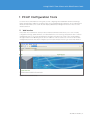
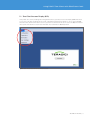
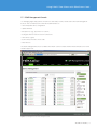
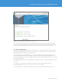
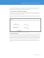
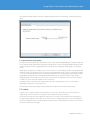
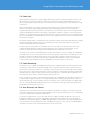
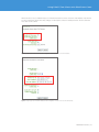
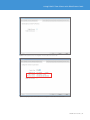
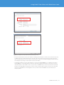
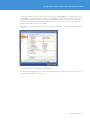
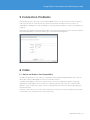
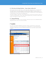
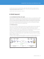
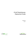
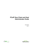
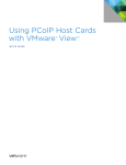
Using PCoIP® Zero Clients with PCoIP Host Cards TECHNICAL NOTES Using PCoIP® Zero Clients with PCoIP Host Cards Table of Contents Preface. . . . . . . . . . . . . . . . . . . . . . . . . . . . . . . . . . . . . . . . . . . . . . . . . . . . . . . . . . . . . . . . . . . . . 3 Additional Support. . . . . . . . . . . . . . . . . . . . . . . . . . . . . . . . . . . . . . . . . . . . . . . . . . . . . . . . . . 3 1 PCoIP Configuration Tools. . . . . . . . . . . . . . . . . . . . . . . . . . . . . . . . . . . . . . . . . . . . . . . . . . 4 1.1 Web Interface. . . . . . . . . . . . . . . . . . . . . . . . . . . . . . . . . . . . . . . . . . . . . . . . . . . . . . . . . 4 1.2 Zero Client Onscreen Display (OSD). . . . . . . . . . . . . . . . . . . . . . . . . . . . . . . . . . . . . 5 1.3 PCoIP Management Console. . . . . . . . . . . . . . . . . . . . . . . . . . . . . . . . . . . . . . . . . . . . 6 2 Firmware. . . . . . . . . . . . . . . . . . . . . . . . . . . . . . . . . . . . . . . . . . . . . . . . . . . . . . . . . . . . . . . . . 7 3 Network Considerations. . . . . . . . . . . . . . . . . . . . . . . . . . . . . . . . . . . . . . . . . . . . . . . . . . . . 7 3.1 Session Bandwidth. . . . . . . . . . . . . . . . . . . . . . . . . . . . . . . . . . . . . . . . . . . . . . . . . . . . . 7 3.1.1 Device Bandwidth Target. . . . . . . . . . . . . . . . . . . . . . . . . . . . . . . . . . . . . . . . . . . 8 3.1.2 Device Bandwidth Floor. . . . . . . . . . . . . . . . . . . . . . . . . . . . . . . . . . . . . . . . . . . . 9 3.1.3 Device Bandwidth Limit. . . . . . . . . . . . . . . . . . . . . . . . . . . . . . . . . . . . . . . . . . . . 9 3.2 Image Quality and Bandwidth Management . . . . . . . . . . . . . . . . . . . . . . . . . . . . . 10 3.2.1 Minimum Image Quality . . . . . . . . . . . . . . . . . . . . . . . . . . . . . . . . . . . . . . . . . . . 10 3.2.2 Maximum Initial Image Quality . . . . . . . . . . . . . . . . . . . . . . . . . . . . . . . . . . . . . 11 3.3 Latency. . . . . . . . . . . . . . . . . . . . . . . . . . . . . . . . . . . . . . . . . . . . . . . . . . . . . . . . . . . . . . 11 3.4 Packet Loss. . . . . . . . . . . . . . . . . . . . . . . . . . . . . . . . . . . . . . . . . . . . . . . . . . . . . . . . . . 12 3.5 Packet Reordering. . . . . . . . . . . . . . . . . . . . . . . . . . . . . . . . . . . . . . . . . . . . . . . . . . . . 12 3.6 Auto-Discovery and Subnets. . . . . . . . . . . . . . . . . . . . . . . . . . . . . . . . . . . . . . . . . . . 12 3.7 Temporal Dithering . . . . . . . . . . . . . . . . . . . . . . . . . . . . . . . . . . . . . . . . . . . . . . . . . . . 15 4 IP Addresses. . . . . . . . . . . . . . . . . . . . . . . . . . . . . . . . . . . . . . . . . . . . . . . . . . . . . . . . . . . . . 15 4.1 DHCP . . . . . . . . . . . . . . . . . . . . . . . . . . . . . . . . . . . . . . . . . . . . . . . . . . . . . . . . . . . . . . . 15 4.2 Determining IP Addresses . . . . . . . . . . . . . . . . . . . . . . . . . . . . . . . . . . . . . . . . . . . . . 15 5 Connection Problems. . . . . . . . . . . . . . . . . . . . . . . . . . . . . . . . . . . . . . . . . . . . . . . . . . . . . 18 6 Video. . . . . . . . . . . . . . . . . . . . . . . . . . . . . . . . . . . . . . . . . . . . . . . . . . . . . . . . . . . . . . . . . . . 18 6.1 Monitor and Graphics Card Compatibility. . . . . . . . . . . . . . . . . . . . . . . . . . . . . . . . 18 6.2 Client Does Not Display Desktop – “Source Signal on Other Port”. . . . . . . . . . 19 6.3 Temporal Dithering . . . . . . . . . . . . . . . . . . . . . . . . . . . . . . . . . . . . . . . . . . . . . . . . . . . 19 7 Audio. . . . . . . . . . . . . . . . . . . . . . . . . . . . . . . . . . . . . . . . . . . . . . . . . . . . . . . . . . . . . . . . . . . 19 8 WAN Support. . . . . . . . . . . . . . . . . . . . . . . . . . . . . . . . . . . . . . . . . . . . . . . . . . . . . . . . . . . . 20 8.1 Local Keyboard and Mouse Host Agent . . . . . . . . . . . . . . . . . . . . . . . . . . . . . . . . . 20 8.2 VPN Connectivity. . . . . . . . . . . . . . . . . . . . . . . . . . . . . . . . . . . . . . . . . . . . . . . . . . . . . 20 9 Frequently Asked Questions. . . . . . . . . . . . . . . . . . . . . . . . . . . . . . . . . . . . . . . . . . . . . . . 21 TECHNICAL NOTES / 2 Using PCoIP® Zero Clients with PCoIP Host Cards Preface This document provides guidelines for configuring, troubleshooting, and optimizing 1:1 (non-virtualized) remote computing using PCoIP host cards and PCoIP zero clients. Topics include: • PCoIP Configuration Tools (Web interface, onscreen display, and Management Console) • Firmware versions • Network considerations and bandwidth management • IP addresses • Connection problems • Video and audio issues • WAN and VPN connectivity Note: VMware® View™ is now capable of brokering 1:1 remote workstation sessions between PCoIP host cards and zero clients. Virtually all the information in this guide, including that on configuration tools, bandwidth and image quality, connection problems, video, audio, and WAN, also applies to 1:1 remote sessions brokered by VMware View. The key differences are that in a VMware View environment, the View Agent must be installed on the host machine, and VMware View serves as the connection broker, so host-client connections (and associated information, such as IP addresses) are configured in View rather than via Teradici configuration tools. Note: The specifications are subject to change without notice. Additional Support Your PCoIP solution vendor should be your first contact for PCoIP support and information. Teradici manages a support site (https://w ww.support.teradici.com) that provides documentation, a knowledge base, and downloads of Teradici firmware and software. The following detailed documents are available in the Documentation section of the Teradici support site. • PCoIP Desktop System Quick Start Guide (TER0809002) • PCoIP Administrative Interface User Manual (TER0606004) • PCoIP VPN Deployment Guide (TER0902002) • PCoIP User Guide (TER0806003) • Using PCoIP Host Cards Brokered by VMware View 4 (TER0911004) You will require a user name and password to access the Teradici support site. Contact [email protected] to request access to the support site. TECHNICAL NOTES / 3 Using PCoIP® Zero Clients with PCoIP Host Cards 1 PCoIP Configuration Tools Several of the recommendations in this guide, such as configuring PCoIP bandwidth utilization and image quality, determining IP addresses, assigning connections, and updating PCoIP firmware, are accomplished via the PCoIP Web interface, zero client onscreen display (OSD) and/or Management Console. These tools are introduced below. 1.1 Web Interface Every PCoIP host card and zero client provides a Web-based interface that allows you to view or modify configuration settings, update firmware, set USB authorization, view event logs, and perform other common management tasks. To access the Web interface, navigate to the PCoIP zero client or host card IP address through a Web browser. Obtaining PCoIP device IP addresses is discussed in Section 4.2. Note that if PCoIP management passwords have been configured, you will require the password to log in to the Web interface. Figure 1: The PCoIP host card Web interface TECHNICAL NOTES / 4 Using PCoIP® Zero Clients with PCoIP Host Cards 1.2 Zero Client Onscreen Display (OSD) Every PCoIP zero client (including PCoIP integrated monitors) provides an onscreen display (OSD) that allows you to view or modify certain PCoIP zero client configuration and network settings. To access the client OSD, disconnect the client from its PCoIP session (or power it on) and use the mouse to access the Options menu at the top left of the Connect screen. Note that PCoIP host cards have no OSD equivalent. Figure 2: Options menu to access OSD from zero client Connect screen TECHNICAL NOTES / 5 Using PCoIP® Zero Clients with PCoIP Host Cards 1.3 PCoIP Management Console For managing larger deployments of PCoIP host cards and/or clients, Teradici offers the PCoIP Management Console. This is a Web-based tool that allows administrators to: • View and update device configuration • Update firmware • Group devices (e.g., by function or location) • Configure and view static host-client connections • View device log files • Control the power state of host cards • Reset devices The PCoIP Management Console is available from PCoIP solution vendors and from the download section of the Teradici support site. Figure 3: PCoIP Management Console Device Management screen TECHNICAL NOTES / 6 Using PCoIP® Zero Clients with PCoIP Host Cards 2Firmware • The latest Tera1 firmware (version 3.1 or later) is recommended unless you are connecting to a Linux host over a high-latency WAN (see below). Firmware 3.1 or later is compatible with both VMware and non-VMware environments. • All PCoIP devices in VMware-brokered environments require firmware 3.1 or later and VMware View agent 4.0.1 or later. • For 1:1 connections to Linux host PCs over high-latency WAN connections that require the PCoIP local keyboard and mouse agent (see Section 8.1), firmware 2.3 is recommended. The Linux version of the PCoIP agent will be updated to support firmware 3.x in the future. • Both the PCoIP host card and client must be at the same firmware level. • Firmware is available from PCoIP solution vendors or from the download section of the Teradici support site. A firmware upgrade is performed via the Web interface or Management Console (see Section 1). Refer to the documentation included with the firmware for details. 3Network Considerations 3.1 Session Bandwidth PCoIP 1:1 remoting hardware requires a minimum peak bandwidth of approximately 1Mbps1. The actual peak bandwidth required to deliver a satisfactory desktop experience will depend on the application, graphics, network, monitor configuration, and user expectations. Peak bandwidth is the bandwidth required to deliver major screen updates quickly. Average bandwidth utilization is typically much lower. The PCoIP protocol can be used over lower bandwidth networks, but the user experience will be impacted as bandwidth decreases. The PCoIP protocol allows specification of three parameters that control bandwidth utilization. These are accessed via Configuration Bandwidth on the Web interface and discussed in later sections. 1. The bandwidth requirements for remote computing with a PCoIP host card are not the same as when using a VMware View 4 virtual desktop host. See Using PCoIP Zero Clients with VMware View 4 (TER0904005). TECHNICAL NOTES / 7 Using PCoIP® Zero Clients with PCoIP Host Cards Figure 4: PCoIP host card Web interface showing bandwidth configuration screen Note: In order to minimize the impact of new remote sessions on the network, the PCoIP protocol initiates sessions at reduced bandwidth and increases bandwidth utilization over the first few seconds. For this reason, you may briefly see low-bandwidth video artifacts in a new session until bandwidth utilization ramps up. 3.1.1 Device Bandwidth Target When a PCoIP session experiences packet loss, the PCoIP protocol scales back bandwidth utilization rapidly to the Device Bandwidth Target, and more slowly below this value. This provides a more even distribution of bandwidth between users sharing a congested network. The recommended Device Bandwidth Target is 0 (zero), which disables the target bandwidth feature. If you discover that active PCoIP sessions on the same network are consistently receiving unequal shares of the network’s bandwidth (e.g., some users are happy with their desktop experience while others are not), consider the following configuration: Device Bandwidth Target = 80% x (Network Bandwidth / Number of Users), provided this bandwidth is at least 1,000 kbps. For example, if four similar users are sharing a 100 Mbps link, set the Device Bandwidth Target to Device Bandwidth Target = (0.8 x 100,000 / 4) = 0.8 x 25,000 = 20,000 kbps From this starting point, adjust Device Bandwidth Target, if necessary based on feedback from your users. TECHNICAL NOTES / 8 Using PCoIP® Zero Clients with PCoIP Host Cards Setting the Device Bandwidth Target is the preferred method for managing bandwidth utilization on a shared network because it still allows individual remote sessions to exploit all available bandwidth when the network is not congested. In contrast, the Device Bandwidth Limit (described in Section 3.1.3) is a hard limit on bandwidth utilization that will restrict the user experience even if no other traffic is on the network. 3.1.2 Device Bandwidth Floor The Device Bandwidth Floor specifies the minimum bandwidth that a remote session will consume when congestion is present and bandwidth is required. Bandwidth utilization will drop below the floor when bandwidth is not required (e.g., when the display is static). This setting is intended for use in networks where persistent packet loss (Section 3.4) or packet reordering (Section 3.5) cannot be eliminated. The best solution is to identify and fix the source of packet loss or packet reordering in the network. While the network problem is being resolved, the PCoIP session experience can be improved by using the Device Bandwidth Floor setting. The default setting of 0 (zero) uses the default bandwidth floor (currently 1,000 kbps for 1:1 sessions). Setting this to a non-zero value (> 1,000 kbps) will give remote users a better user experience by increasing the minimum bandwidth the remote session will attempt to use in the presence of persistent packet loss. However, this should be done in consultation with users and only if network bandwidth and demands are well understood, because the higher this value is set, the less flexibility the PCoIP protocol has to adjust to real network congestion. As a result, setting this value too high can result in a significantly degraded overall experience if the network becomes oversubscribed, that is, the combined traffic from all remote sessions exceeds the bandwidth that the network can provide). Once the network packet loss/reordering issue in the network has been resolved, reset the Device Bandwidth Floor to 0 (zero). 3.1.3 Device Bandwidth Limit The Device Bandwidth Limit defines the maximum peak bandwidth that a PCoIP session will consume and is provided primarily for testing purposes, but can sometimes be useful in production deployments. • The Device Bandwidth Limit setting on the host card limits bandwidth on traffic from the host to the client (primarily display data). This represents the vast majority of bandwidth utilization. • The Device Bandwidth Limit setting on the client limits bandwidth on traffic from the client to the host (e.g., USB or microphone audio data). • The bandwidth limit range is 1,000 to 220,000 kbps. The recommended setting for the Device Bandwidth Limit is 0 (zero), which configures the PCoIP processor to adjust the bandwidth solely based on network congestion with no limit. The processor will maximize the user experience based on the bandwidth available at any given moment. However, a non-zero setting (> 1,000 kbps) may be appropriate in situations where there are network constraints, such as: • If there is a known network bandwidth constraint between the PCoIP host and client, set the Device Bandwidth Limit to approximately 90% of this bandwidth limit. – For example, if the PCoIP host is on a 100 Mbps network but the zero client is connected on a 6 Mbps ADSL link, set the Device Bandwidth Limit to approximately 90% x 6 Mbps = 5,400 kbps. • If you are experiencing congestion and packet loss on a network being shared between PCoIP sessions and other types of network traffic, consider setting the Device Bandwidth Limit to constrain aggregate PCoIP session bandwidth. – For example, if you have four similar users (similar application demands and priority) sharing a 6 Mbps link with other network traffic, setting the Device Bandwidth Limit to 70% of the link bandwidth (70% x 6,000 kbps = 4,200 kbps) will help reduce congestion on the network. TECHNICAL NOTES / 9 Using PCoIP® Zero Clients with PCoIP Host Cards If you must limit bandwidth utilization on your network, use the Device Bandwidth Target setting first before adjusting the Device Bandwidth Limit. Get input from your users as you adjust these settings to find the bandwidth limit at which users are satisfied with their desktop experience. 3.2 Image Quality and Bandwidth Management The PCoIP protocol constantly monitors the available bandwidth and the complexity of the graphics being delivered and adjusts the image quality and frame rate to provide the best user experience (image quality and desktop responsiveness) under changing conditions. There are two configuration parameters to adjust the imaging quality of the session. These are accessed via Configuration Image on the zero client Web interface. These parameters are not available on the PCoIP host card. Figure 5: Image quality settings screen under Configuration Image in zero client Web interface 3.2.1 Minimum Image Quality The Minimum Image Quality slider allows you to balance image quality and frame rate when network bandwidth is limited. Some use cases, such as those involving onscreen motion and rapid screen changes, may benefit from lower-quality images at a higher frame rate (slider toward “Reduced,” meaning “optimize for frame rate”) while others, such as those requiring more careful examination of static screen content, may be better served by higher-quality images at a lower frame rate (slider toward “Perception-Free,” meaning “optimize for frame image quality”). The default setting for Minimum Image Quality is 40, which tends to optimize for frame rate. This setting affects image display only when network bandwidth is constrained. When bandwidth is not constrained, the PCoIP protocol will deliver perception-free quality regardless of the Minimum Image Quality setting. TECHNICAL NOTES / 10 Using PCoIP® Zero Clients with PCoIP Host Cards Note: Minimum Image Quality can also be configured using the OSD via User Settings Image tab as shown below. Figure 6: Minimum Image Quality setting under User Settings Image in zero client OSD 3.2.2Maximum Initial Image Quality The Maximum Initial Image Quality slider can be used to reduce network bandwidth peaks caused by significant screen changes. Reducing Maximum Initial Image Quality may also reduce average bandwidth utilization under certain circumstances (this is highly dependent on the details of your application and graphics, as explained below). Reducing this setting limits the quality of the first video frame of a screen change, thereby reducing bandwidth utilization. Because of the PCoIP protocol’s progressive build capability, all static regions of the image will build to a lossless state during subsequent screen refreshes regardless of this setting. Reducing the Maximum Initial Image Quality setting will reduce average bandwidth requirements in situations when the screen image is changing rapidly over a period of time, because in such situations, the individual screens never have a chance to build to a lossless state until the final screen in a sequence. The default value for Maximum Initial Image Quality is 90 but it can generally be set to 70 or 80 without impacting the experience of the average user. Note: Maximum Initial Image Quality must be greater than or equal to the Minimum Image Quality. 3.3 Latency 1:1 PCoIP sessions currently support network latency of up to 150ms. The PCoIP protocol can be used over higher-latency networks, but the user experience will be impacted as latency increases. System responsiveness becomes sluggish for many users at 40 – 60ms of network latency. If WAN latency is causing usability problems, such as poor mouse responsiveness or dropped keystrokes, consider installing the PCoIP host agent that improves keyboard and mouse performance over high-latency networks. See Section 8.1 for details on the PCoIP host agent. TECHNICAL NOTES / 11 Using PCoIP® Zero Clients with PCoIP Host Cards 3.4 Packet Loss Typical symptoms of packet loss include sluggish desktop responsiveness and blurry images. Packet loss can affect both the user experience and USB connectivity even if the base latency and bandwidth meet PCoIP protocol requirements. Packet loss below 0.1% should not have a noticeable impact on user experience or USB connectivity. While network packet loss is usually specified as a percentage (e.g., 0.1%), physical networks typically lose packets in small bursts rather than being randomly dispersed throughout time. However, if a network is experiencing random, persistent packet loss, the PCoIP protocol will interpret this as network congestion and reduce the bandwidth it transmits in an attempt to eliminate this “phantom” congestion. Since the persistent packet loss is coming from the network itself rather than from congestion, the PCoIP session eventually reaches the “floor” bandwidth (Device Bandwidth Floor, Section 3.1.2) and will result in a lower level of experience than the network can support. Note: Many “WAN emulators” simulate packet loss as persistent, random events rather than the bursts of packet loss that actual WANs experience. Thus, if you are testing with one of these WAN emulators, you will also observe this artificially lower user experience. The best solution to this problem is to find and fix the source of packet loss in the network (or use a more sophisticated WAN emulator). While the network packet loss issue is being resolved, the PCoIP session experience can be improved by using the Device Bandwidth Floor setting (see Section 3.1.2) Note that misuse of the Device Bandwidth Floor can also create packet loss. If the combined “floor bandwidth” of multiple PCoIP sessions on the same network exceeds the capacity of that network, the PCoIP protocol will attempt to transmit more data than the network can accommodate, resulting in continuous packet loss. To prevent this, ensure your network can provide the combined floor bandwidth for all the sessions sharing a common network link and adjust session floor bandwidths (or network capacity) if necessary. 3.5 Packet Reordering The PCoIP protocol is capable of handling packets that arrive in a different order from that in which they were sent because a small amount of packet reordering can be expected in a WAN. However, if a packet does not arrive within a certain time window, it is considered “lost” by the PCoIP protocol even though it may eventually arrive. This is done to preserve the interactivity of the user experience: in a dynamic environment, significantly delayed packets are often no longer relevant. However, if the network is consistently delivering packets “late,” the experience will be similar to a network with persistent packet loss. Thus, if your PCoIP sessions are consistently operating at the “floor bandwidth” even though the network is not congested and no significant packet loss is being reported, packet reordering may be the cause. A device in the network path (e.g., a router or WAN accelerator) is the likely source of persistent packet reordering. While the source is being identified and fixed, the PCoIP session experience can be improved by raising the Device Bandwidth Floor setting (see Section 3.1.2). 3.6 Auto-Discovery and Subnets Many PCoIP zero clients ship with auto-discovery turned on by default. This feature locates PCoIP host cards on the same subnet as the client and is intended primarily for test rather than production use. Use of DNS-SRV records is recommended for production deployments. For production deployments, or if your host and client are on different subnets, disable auto-discovery via Configuration Discovery on the zero client OSD or Web interface and configure the session information manually by entering the IP address (or FQDN) and MAC address of the peer host card under Configuration Session in the zero client Web interface or zero client OSD (see Figures 7, 8, 9, 10). The host card MAC address is printed on a sticker on the card itself and on the box of most host cards. TECHNICAL NOTES / 12 Using PCoIP® Zero Clients with PCoIP Host Cards When auto-discovery is enabled and you click the Connect button on the client, the client displays only the first five host cards that it finds. These may change on subsequent connection attempts if there are more than five host cards on the subnet. Figure 7: Disabling SLP and Host Discovery under Configuration Discovery in the zero client Web interface Figure 8: Configuring the peer IP and MAC addresses under Configuration Session in the zero client Web interface TECHNICAL NOTES / 13 Using PCoIP® Zero Clients with PCoIP Host Cards Figure 9: Disabling auto-discovery in the Configuration Discovery tab of the zero client OSD Figure 10: Configuring the host IP and MAC addresses in the Configuration Session tab of the zero client OSD TECHNICAL NOTES / 14 Using PCoIP® Zero Clients with PCoIP Host Cards 3.7 Temporal Dithering Temporal dithering is a technique employed by some graphics cards to simulate colors that they cannot natively display by rapidly changing the colors of pixels, tricking the eye into seeing “in-between” colors. During PCoIP remote sessions, temporal dithering can cause extremely high bandwidth utilization because the rapidly changing pixels force the PCoIP protocol to constantly deliver large screen updates to the remote desktop. There is no acceptable way to reduce bandwidth consumption caused by temporal dithering because lowering the PCoIP Device Bandwidth Target or Device Bandwidth Limit will impair user experience with reduced responsiveness and image quality. However, some graphics cards allow temporal dithering to be disabled, especially under Linux. Consult your graphics card documentation or contact your card vendor for details on disabling temporal dithering. The Teradici Knowledge Base also contains information on temporal dithering and how to disable it. 4IP Addresses 4.1 DHCP The PCoIP client and host are set to “DHCP client” mode by default, meaning the host and client IP addresses are assigned by the DHCP server on your IP network. If your IP network does not have a DHCP server, the client and host card will fall back to a static IP address mode after a timeout period of approximately two minutes. In the fallback static IP address mode, you can access the client and host Web interfaces to disable DHCP client mode and assign a static IP address. The client’s fallback IP address is 192.168.1.50 and the host’s fallback IP address is 192.168.1.100. 4.2 Determining IP Addresses Any computer connected to a corporate network or the Internet has a standard network card with an IP address. In addition, the PCoIP host card has a dedicated Ethernet jack that delivers PCoIP remote desktop data to the client. This host card Ethernet jack also has its own IP address. As a result, a PCoIP host computer on a corporate network or the Internet has two different IP addresses – one for the standard network card and one for the PCoIP host card. The PCoIP zero client has one IP address. There are several ways to find the PCoIP host and client IP addresses: • To find the address of the PCoIP zero client, access Options Configuration Network tab on the client OSD. If the client is statically connected to a host card, the host card IP address is displayed as the “Peer IP Address” on the Session tab. TECHNICAL NOTES / 15 Using PCoIP® Zero Clients with PCoIP Host Cards Figure 11: Client IP address on OSD Network tab Figure 12: Host IP address on OSD Session tab (if client is statically paired to the host) • If the host and client are on the same subnet containing a small number of PCoIP devices and host discovery is enabled, click the client Connect button. The auto-discovery function will locate host cards. However, if there are many PCoIP hosts on the subnet, only the first five devices located are displayed, and the five that are displayed may change on subsequent connection attempts. • To find the IP address of a host card, navigate to “pcoip-host-<MAC-ADDRESS>” in a Web browser where <MAC-ADDRESS> is the MAC address of the host card with all hyphens and spaces removed (e.g., for host card MAC address 00-1C-B3-BF-22-45 use “pcoip-host-001CB3BF2245”). This will open the host card Web interface. The MAC address is printed on a sticker on the card itself and on the box of most host cards and may also be under Options Configuration Session tab on the client OSD if the client and host are statically paired. TECHNICAL NOTES / 16 Using PCoIP® Zero Clients with PCoIP Host Cards • To find the IP address of a zero client, navigate to “pcoip-portal -<MAC-ADDRESS>” in a Web browser where <MAC-ADDRESS> is the MAC address of the client with all hyphens and spaces removed (e.g., for zero client MAC address 00-1C-B3-BF-22-45, use “pcoip-portal-001CB3BF2245”). This will open the zero client Web interface. The client MAC address is printed on a sticker on the outside of the client and is also under the Options Information tab on the client OSD. • If the PCoIP host agent is installed, open the PCoIP Agent (click the PCoIP icon in the system tray) and select Network. Figure 13: Network information in PCoIP host agent application (with system tray icon circled) • Look up the IP address in your DHCP server client table. • Use the PCoIP Management Console, a Web-based management tool available from various PCoIP solution vendors and from Teradici (see Section 1.3). TECHNICAL NOTES / 17 Using PCoIP® Zero Clients with PCoIP Host Cards 5Connection Problems If the Connect button on the client onscreen display (OSD) is inactive or if the client cannot discover any host cards on the IP network, check the network connection and confirm the Ethernet switch or router is on. Under Options Diagnostics on the client OSD, you can ping a known IP address to check for reachability (see Figure 14). Ensure that your firewall is not blocking PCoIP traffic. For specific port information, refer to the entry “What are the required TCP/UDP ports for PCoIP Technology?” in the Teradici Knowledge Base. Figure 14: Pinging an IP address from the zero client OSD (Options Diagnostics Ping tab) 6Video 6.1 Monitor and Graphics Card Compatibility In addition to DVI monitors, zero clients are compatible with analog VGA and digital HDMI monitors. Attach a DVI-to-VGA or DVI-to-HDMI adapter to the zero client’s DVI connector. In addition to DVI graphics cards, a host card can also be connected to a DisplayPort graphics card using a DisplayPort-to-DVI adapter. The host card is not compatible with VGA video cards. Use of a VGA-to-DVI adapter to connect a VGA video output to the host card’s DVI input will result in no video being displayed on the remote desktop. Ensure the correct driver for your video card is installed. Incorrect drivers can cause the display to flicker, blink, or freeze. Drivers are available from your video card vendor. TECHNICAL NOTES / 18 Using PCoIP® Zero Clients with PCoIP Host Cards 6.2 Client Does Not Display Desktop – “Source Signal on Other Port” When using the client with a single monitor (or with a single PCoIP integrated monitor), it is possible for the video signal to be sent to the video output with no monitor. When this happens, the easiest solution is to reverse the connectors connecting the graphics card to the PCoIP host card or to connect the monitor to the other DVI output on the client (if you are using a client connected to a separate monitor). Another alternative is to remap (swap) the monitors in the host operating system. Note that some graphics cards must be connected when they boot or they do not provide video output. If you connected or switched the video connector cables after booting the host PC, you may have to restart the host PC after connecting the video cables to restore video. 6.3 Temporal Dithering Temporal dithering is a technique used by some graphics cards that can cause excessive bandwidth utilization during PCoIP remote sessions. See Section 3.7 for details. 7 Audio Zero clients use the Realtek High-Definition Audio Codec. Windows 7 and Vista natively contain an HD Audio driver for this Codec. For other operating systems, including Windows XP, download and install the High-Definition (HD) Audio Codec driver from http://www.realtek.com to use the PCoIP system’s full audio capabilities. Figure 15: Realtek software driver download page TECHNICAL NOTES / 19 Using PCoIP® Zero Clients with PCoIP Host Cards To enable audio, open the host card Web interface, enable audio under Permissions Audio and restart the host. When using 64-bit Windows Vista or Windows 7 on the host PC, also enable 64-bit on the same configuration page. Do the same for the client. Ensure the audio connectors are properly connected. 8WAN Support 8.1 Local Keyboard and Mouse Host Agent Teradici offers PCoIP host agent software designed to provide faster response to mouse input and more reliable keyboard function over high-latency networks by rendering the mouse and terminating the keyboard locally on the zero client. This host agent package is available from PCoIP solution vendors and from the download section of the Teradici support site. Carefully follow the documentation included with the host agent package because there are several steps that must be performed in a specific order. The agent functionality will not work if you install the agent package without performing the prior steps. Also note that there are separate agent packages for Windows and Linux host operating systems. 8.2 VPN Connectivity PCoIP sessions can operate in a WAN environment that traverses the public Internet. This type of deployment requires the user to install and configure additional network equipment that implements a VPN tunnel. PCoIP protocol data packets are IPSec-ESP encrypted and do not have any port numbers external to encryption. As a result, the packets are not compatible with networking equipment that implements Network Address Translation (NAT), which is used by the Internet and some corporate WANs. In order to use NAT networking equipment with the PCoIP protocol, network traffic must be encapsulated in a tunneling protocol. This tunneling can be achieved using a hardware VPN. The VPN tunneling allows data packets to remap from a public IP address space to and from a private IP address space. Below is a simplified diagram showing such a scenario. For details, see PCoIP VPN Deployment Guide (TER0902002), which discusses Network Address Translation, IPSec, PCoIP connection requirements, and configuration of the VPN, routers, and PCoIP endpoints. Figure 16: Simplified diagram of a PCoIP zero client connecting over public Internet via VPN TECHNICAL NOTES / 20 Using PCoIP® Zero Clients with PCoIP Host Cards 9Frequently Asked Questions Why is my PCoIP session using >100 Mbps almost all of the time? This is typically caused because temporal dithering is enabled on your graphics card. See Section 3.7 for more details. Why is my PCoIP session performing poorly when my network is not busy? This problem is typically caused by persistent packet loss or significant packet reordering. See sections 3.4 and 3.5 for details and how to resolve these issues. Why are some users reporting good user experiences while others on the same network are reporting a poor experience? “Unfair” sharing of the network may cause this. See Section 3.1.1 to understand the use of the Device Bandwidth Target setting to correct this situation. Why is my pointer lagging so much? This is probably caused by the latency on the network being greater than 40ms. See Section 8.1 to understand how to install the local mouse and keyboard support. How do I connect a zero client to a host system behind the corporate firewall? You will need a hardware VPN device to provide this connection. For details, see PCoIP VPN Deployment Guide (TER 0902002), which discusses Network Address Translation, IPSec, PCoIP connection requirements, and configuration of the VPN, routers, and PCoIP endpoints. Also, refer to the entry “What are the required TCP/UDP ports for PCoIP Technology?” in the Teradici Knowledge Base. Why does my PCoIP session seem less crisp when I first connect? In order to minimize the impact of new remote sessions on the network, the PCoIP protocol initiates sessions at reduced bandwidth and increases bandwidth utilization over the first few seconds. For this reason, you may briefly see low-bandwidth video artifacts until bandwidth utilization ramps up. VMware, Inc. 3401 Hillview Avenue Palo Alto CA 94304 USA Tel 877-486-9273 Fax 650-427-5001 www.vmware.com Copyright © 2010 VMware, Inc. All rights reserved. This product is protected by U.S. and international copyright and intellectual property laws. VMware products are covered by one or more patents listed at http://www.vmware.com/go/patents. VMware is a registered trademark or trademark of VMware, Inc. in the United States and/or other jurisdictions. PCoIP is a registered trademark of Teradici Corporation in the United States and/or other countries. All other marks and names mentioned herein may be trademarks of their respective companies. Item No: VMW_10Q1_WP_PCoIPZeroHost_EN_P21_R1