1
• SAFETY PRECAUTIONS •
(Always read these instructions before using this equipment.)
Before using this product, please read this manual and the relevant manuals introduced in this manual
carefully and pay full attention to safety to handle the product correctly.
The instructions given in this manual are concerned with this product. For the safety instructions of the
programmable controller system, please read the CPU module user's manual.
In this manual, the safety instructions are ranked as " ! WARNING" and " ! CAUTION".
WARNING
Indicates that incorrect handling may cause hazardous conditions,
resulting in death or severe injury.
CAUTION
Indicates that incorrect handling may cause hazardous conditions,
resulting in minor or moderate injury or property damage.
Note that the ! CAUTION level may lead to a serious consequence according to the circumstances.
Always follow the instructions of both levels because they are important to personal safety.
Please save this manual to make it accessible when required and always forward it to the end user.
[Design Instructions]
!
WARNING
• For data change, program change, and status control made to the PLC which is running from a
Personal computer, configure the interlock circuit externally so that the system safety is
ensured. The action to be taken for the system at the occurrence of communication errors
caused by such as loose cable connection must be determined for online operation of PLC from
Personal computers.
[Design Instructions]
!
CAUTION
• Be sure to read the manual careful and exercise an appropriate amount of caution connecting to
PLC CPU and performing online operations (PLC CPU program change during RUN, forced
input/output operation, RUN-STOP or other operation condition changes, remote control
operation) while the personal computer is operating.
Regarding the PLC CPU program change during RUN (Write during RUN), the program may be
corrupted or have other problems depending on operation conditions. Exercise the appropriate
amount of caution with regard to the Caution points in section 16.9.
A-1
A-1
• CONDITIONS OF USE FOR THE PRODUCT •
(1) Mitsubishi programmable controller ("the PRODUCT") shall be used in conditions;
i) where any problem, fault or failure occurring in the PRODUCT, if any, shall not lead to any major or
serious accident; and
ii) where the backup and fail-safe function are systematically or automatically provided outside of the
PRODUCT for the case of any problem, fault or failure occurring in the PRODUCT.
(2) The PRODUCT has been designed and manufactured for the purpose of being used in general
industries.
MITSUBISHI SHALL HAVE NO RESPONSIBILITY OR LIABILITY (INCLUDING, BUT NOT LIMITED
TO ANY AND ALL RESPONSIBILITY OR LIABILITY BASED ON CONTRACT, WARRANTY, TORT,
PRODUCT LIABILITY) FOR ANY INJURY OR DEATH TO PERSONS OR LOSS OR DAMAGE TO
PROPERTY CAUSED BY the PRODUCT THAT ARE OPERATED OR USED IN APPLICATION NOT
INTENDED OR EXCLUDED BY INSTRUCTIONS, PRECAUTIONS, OR WARNING CONTAINED IN
MITSUBISHI'S USER, INSTRUCTION AND/OR SAFETY MANUALS, TECHNICAL BULLETINS AND
GUIDELINES FOR the PRODUCT.
("Prohibited Application")
Prohibited Applications include, but not limited to, the use of the PRODUCT in;
y Nuclear Power Plants and any other power plants operated by Power companies, and/or any other
cases in which the public could be affected if any problem or fault occurs in the PRODUCT.
y Railway companies or Public service purposes, and/or any other cases in which establishment of a
special quality assurance system is required by the Purchaser or End User.
y Aircraft or Aerospace, Medical applications, Train equipment, transport equipment such as Elevator
and Escalator, Incineration and Fuel devices, Vehicles, Manned transportation, Equipment for
Recreation and Amusement, and Safety devices, handling of Nuclear or Hazardous Materials or
Chemicals, Mining and Drilling, and/or other applications where there is a significant risk of injury to
the public or property.
Notwithstanding the above, restrictions Mitsubishi may in its sole discretion, authorize use of the
PRODUCT in one or more of the Prohibited Applications, provided that the usage of the PRODUCT is
limited only for the specific applications agreed to by Mitsubishi and provided further that no special
quality assurance or fail-safe, redundant or other safety features which exceed the general
specifications of the PRODUCTs are required. For details, please contact the Mitsubishi
representative in your region.
A-2
A-2
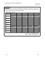
REVISIONS
The manual number is given on the bottom left of the back cover.
Print Date
Manual Number
Revision
May, 2004
SH(NA)-080464ENG-A First edition
Dec., 2004
SH(NA)-080464ENG-B
Correction
Section 7.12
May, 2007
SH(NA)-080464ENG-C
Correction
Section 9.5
Nov., 2009
SH(NA)-080464ENG-D
Addition
CONDITIONS OF USE FOR THE PRODUCT
Correction
SAFETY PRECAUTIONS, About Manuals, Product Makeup,
Section 4.1
Deletions
SOFTWARE USER REGISTRATION
Japanese Manual Version SH-080440-G
This manual confers no industrial property rights or any rights of any other kind, nor does it confer any patent licenses.
Mitsubishi Electric Corporation cannot be held responsible for any problems involving industrial property rights which
may occur as a result of using the contents noted in this manual.
© 2004 MITSUBISHI ELECTRIC CORPORATION
A-3
A-3
INTRODUCTION
Thank you for choosing the Mitsubishi MELSOFT series comprehensive Factory Automation software.
Read this manual and make sure you understand the functions and performance of MELSEC series PLC
thoroughly in advance to ensure correct use.
CONTENTS
SAFETY PRECAUTIONS..............................................................................................................................A- 1
CONDITIONS OF USE FOR THE PRODUCT .............................................................................................A- 2
REVISIONS ....................................................................................................................................................A- 3
CONTENTS....................................................................................................................................................A- 4
How to Use This Manual................................................................................................................................A- 9
About Manuals ...............................................................................................................................................A-10
Generic Terms and Abbreviations Used in This Manual ..............................................................................A-11
Product Makeup .............................................................................................................................................A-13
1 OVERVIEW
1- 1 to 1- 6
1.1 Features ................................................................................................................................................... 1- 1
2 SYSTEM CONFIGURATION
2- 1 to 2-12
2.1 System Configuration............................................................................................................................... 2- 1
2.1.1 Connection from the serial/USB port ................................................................................................ 2- 1
2.1.2 Connection from the Interface Board ............................................................................................... 2- 6
2.1.3 Connection from GX Explorer installed in the PC CPU module...................................................... 2- 7
2.1.4 System Equipment Lists ................................................................................................................... 2- 8
2.2 Operating Environment ............................................................................................................................ 2-11
3 MAIN FUNCTION
3- 1 to 3- 2
4 INSTALLATION AND UNINSTALLATION
4- 1 to 4-11
4.1 Installation ................................................................................................................................................ 4- 1
4.2 Uninstallation............................................................................................................................................ 4- 6
4.3 Installing the USB Driver.......................................................................................................................... 4- 8
5 BASIC OPERATIONS
5- 1 to 5-31
5.1 Starting and Exiting .................................................................................................................................. 55.1.1 (1) Starting ......................................................................................................................................... 55.1.1 (2) User setting name specification .................................................................................................. 55.1.2 Exiting ................................................................................................................................................ 55.2 Screen Layout .......................................................................................................................................... 55.2.1 Screen layout..................................................................................................................................... 5A-4
A-4
2
2
3
4
5
5
5.2.2 Menu lists........................................................................................................................................... 5- 8
5.2.3 Icon lists............................................................................................................................................. 5-16
5.2.4 Shortcut key lists ............................................................................................................................... 5-18
5.3 Text input (Applicable character type and max. number of characters) ................................................ 5-20
5.4 Operations for PC Side Window.............................................................................................................. 5-22
5.4.1 Displaying the data in the personal computer .................................................................................. 5-22
5.5 Operations for PLC Side Window............................................................................................................ 5-24
5.5.1 Displaying the PLC configuration information .................................................................................. 5-24
5.5.2 Displaying the data in the PLC CPU................................................................................................. 5-26
5.5.3 Update of network configuration information.................................................................................... 5-30
6 FILE OPERATION
6- 1 to 6-10
6.1 Creating a New User Setting Name ........................................................................................................ 6- 1
6.2 Opening a User Setting Name................................................................................................................. 6- 1
6.3 Saving the User Setting Name ................................................................................................................ 6- 2
6.4 Saving the User Setting Name As........................................................................................................... 6- 3
6.5 Deleting a User Setting Name ................................................................................................................. 6- 5
6.6 Import/Export............................................................................................................................................ 6- 6
6.7 Opening a Network Configuration Information........................................................................................ 6- 8
6.8 Saving the Network Configuration Information ....................................................................................... 6- 9
6.9 Saving the Network Configuration Information As .................................................................................. 6- 9
6.10 Deleting a Network Configuration Information ...................................................................................... 6-10
7 PROJECT OPERATION
7- 1 to 7-39
7.1 Creating New Project Internal Parts ........................................................................................................ 7- 1
7.1.1 Displaying system data creation screen........................................................................................... 7- 1
7.1.2 Creating a folder ................................................................................................................................ 7- 2
7.1.3 FTP site setting.................................................................................................................................. 7- 3
7.2 Cutting/Pasting data................................................................................................................................. 7- 6
7.3 Copying/Pasting data............................................................................................................................... 7- 7
7.4 Selecting all data ...................................................................................................................................... 7- 8
7.5 Uploading Data from PLC........................................................................................................................ 7- 9
7.6 Downloading Data to PLC ....................................................................................................................... 7-13
7.7 Deleting PLC data ................................................................................................................................... 7-16
7.8 PLC Batch Operation ............................................................................................................................... 7-18
7.9 Relating a Target Name and a Project.................................................................................................... 7-20
7.9.1 Detailed settings for target name and project relation ..................................................................... 7-21
7.10 Keyword/Password ................................................................................................................................ 7-24
7.10.1 Keyword/Password registration ...................................................................................................... 7-24
7.10.1 (1) Keyword registration (QnA/A/FXCPU) ..................................................................................... 7-24
7.10.1 (2) Password registration (Specific to Q CPU(Q mode) ............................................................... 7-27
7.10.2 Keyword/Password delete .............................................................................................................. 7-29
7.11 Search .................................................................................................................................................... 7-31
7.12 Consistency Check ................................................................................................................................ 7-33
7.13 Rename.................................................................................................................................................. 7-35
7.14 Delete ..................................................................................................................................................... 7-35
A-5
A-5
7.15 Backup.................................................................................................................................................... 7-36
7.16 Restore ................................................................................................................................................... 7-37
7.17 Backup Arrangement ............................................................................................................................. 7-38
7.18 Running the Relevant Application ......................................................................................................... 7-39
7.19 Displaying Property Information ............................................................................................................ 7-39
8 CONNECTION TARGET SPECIFICATION
8- 1 to 8- 30
8.1 Network Configuration Analysis Specification......................................................................................... 8- 1
8.1.1 Network configuration information display/operation range............................................................. 8- 5
8.1.2 Notes on Network Configuration Information ................................................................................... 8- 7
8.2 Connection Target Name......................................................................................................................... 8-10
8.2.1 Accessing the host station ................................................................................................................ 8-12
8.2.2 Accessing the other station............................................................................................................... 8-15
8.2.3 Accessing multiple CPU.................................................................................................................... 8-20
8.2.3 (1) Access to other CPU in multiple CPU system ............................................................................ 8-20
8.2.3 (2) Network access via multiple CPUs ............................................................................................. 8-22
8.3 Access Data Name .................................................................................................................................. 8-25
8.4 MELSOFT Connection............................................................................................................................. 8-28
9 INVESTIGATION AND CONFIRMATION
9- 1 to 9-108
9.1 PLC Status Monitor .................................................................................................................................. 9- 1
9.2 Device Monitor ......................................................................................................................................... 9- 3
9.3 Timing Chart............................................................................................................................................. 9- 9
9.4 Trace......................................................................................................................................................... 9-13
9.5 Ladder Monitor ......................................................................................................................................... 9-20
9.5.1 Ladder monitor split display .............................................................................................................. 9-22
9.5.2 Cancellation of ladder monitor split display ...................................................................................... 9-23
9.5.3 Searching devices in a ladder monitor ............................................................................................. 9-24
9.5.4 Searching step No./block No. in a ladder monitor............................................................................ 9-25
9.5.5 Finding ON/OFF cause for a ladder monitor .................................................................................... 9-26
9.6 Local Device Monitor ............................................................................................................................... 9-27
9.7 Error Diagnostics...................................................................................................................................... 9-29
9.8 Operation Analysis .................................................................................................................................. 9-33
9.8.1 Operation analysis setting................................................................................................................. 9-35
9.9 PLC Diagnostics....................................................................................................................................... 9-50
9.10 Network Diagnostics .............................................................................................................................. 9-55
9.10.1 Network diagnostics ........................................................................................................................ 9-55
9.10.1 (1) Error history monitor .................................................................................................................. 9-57
9.10.1 (2) Network monitor details ............................................................................................................. 9-59
9.10.1 (3) Other station information ........................................................................................................... 9-60
9.10.1 (4) Network test ............................................................................................................................... 9-62
9.10.1 (5) Loop test .................................................................................................................................... 9-64
9.10.1 (6) Setup confirmation test.............................................................................................................. 9-65
9.10.1 (7) Station order check test............................................................................................................. 9-67
9.10.1 (8) Communication test................................................................................................................... 9-69
9.10.2 CC-Link / CC-Link/LT diagnostics .................................................................................................. 9-70
A-6
A-6
9.10.2(1) Conducting a line test ................................................................................................................. 9-73
9.10.2(2) Other station monitor .................................................................................................................. 9-74
9.10.3 Ethernet diagnostics........................................................................................................................ 9-76
9.10.3(1) Ethernet diagnostics <Parameter status> ................................................................................. 9-78
9.10.3(2) Ethernet diagnostics <Error log>................................................................................................ 9-80
9.10.3(3) Ethernet diagnostics <Status of each connection> ................................................................... 9-82
9.10.3(4) Ethernet diagnostics < Status of each protocol>....................................................................... 9-83
9.10.3(5) Ethernet diagnostics <LED status>............................................................................................ 9-85
9.10.3(6) Ethernet diagnostics <Received e-mail information>................................................................ 9-86
9.10.3(7) Ethernet diagnostics <Send e-mail information>....................................................................... 9-87
9.10.3(8) Ethernet diagnostics <PING test>.............................................................................................. 9-88
9.10.3(9) Ethernet diagnostics <Loopback test>....................................................................................... 9-91
9.11 System Monitor ...................................................................................................................................... 9-94
9.11.1 Online module change ................................................................................................................... 9-99
9.12 Alarm Notification ................................................................................................................................. 9-102
9.12.1 Alarm notification setting............................................................................................................... 9-105
10 ACTUAL OPERATION AND TEST
10- 1 to 10- 8
10.1 Remote Operation................................................................................................................................ 10- 1
10.2 Device Test .......................................................................................................................................... 10- 4
11 OTHERS
11- 1 to 11-11
11.1 Tool....................................................................................................................................................... 11- 1
11.1.1 Customize...................................................................................................................................... 11- 1
11.1.1(1) Toolbar ...................................................................................................................................... 11- 1
11.1.1(2) Easy menu ................................................................................................................................ 11- 2
11.1.2 Option ............................................................................................................................................ 11- 4
11.1.3 Security setting.............................................................................................................................. 11- 6
11.1.4 Operation log ................................................................................................................................. 11- 8
11.1.5 Auto-start setting ........................................................................................................................... 11-10
11.2 Help ...................................................................................................................................................... 11-11
12 ERROR MESSAGES FOR MELSOFT CONNECTION
APPENDIX
12- 1 to 12- 2
App.- 1 to App.-33
Appendix.1 Access Ranges in MELSECNET (II/10/H) Systems.....................................................Appendix- 1
Appendix.1.1 Access Range in MELSECNET (II) .......................................................................Appendix- 1
Appendix.1.2 Access Range for A series Start ...........................................................................Appendix- 3
Appendix.1.3 Access Range for QnA series Start ......................................................................Appendix- 5
Appendix.1.4 Access Range for Q series Start ...........................................................................Appendix- 8
Appendix.2 MELSECNET/10, MELSECNET/H Board Access Ranges ........................................Appendix-10
Appendix.2.1 MELSECNET/10 Board, MELSECNET/H Board .................................................Appendix-10
Appendix.2.1.1 A series start .......................................................................................................Appendix-11
A-7
A-7
Appendix.2.1.2 QnA series start ..................................................................................................Appendix-13
Appendix.2.1.3 Q series start .......................................................................................................Appendix-15
Appendix.2.2 Access Range via an Ethernet Board ...................................................................Appendix-16
Appendix.2.3 Access range via CC-Link (AJ65BT-G4) ..............................................................Appendix-19
Appendix 2.4 Access Range via a Computer Link Module .........................................................Appendix-20
Appendix 2.5 Access Range via Serial Communication .............................................................Appendix-22
Appendix 2.6 Access Range for Mixed System ..........................................................................Appendix-23
Appendix 3 PLC CPU Version Correspondence Table ..................................................................Appendix-25
Appendix 3.1 QnACPU function version ......................................................................................Appendix-25
Appendix 3.2 Q4ARCPU function version ...................................................................................Appendix-26
Appendix 3.3 QCPU function version ..........................................................................................Appendix-27
Appendix 4 Specifying New Devices ...............................................................................................Appendix-28
Appendix 5 Examples of Wiring RS-232 Cable for Connection of C24 and Personal Computer .Appendix-29
Appendix 5.1 ACPU .....................................................................................................................Appendix-29
Appendix 5.2 QnACPU ................................................................................................................Appendix-31
Appendix 5.3 QCPU .....................................................................................................................Appendix-33
INDEX
A-8
Index- 1 to Index- 3
A-8
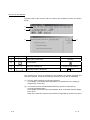
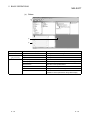
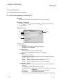
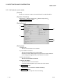
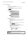
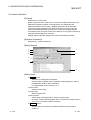
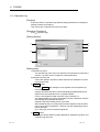
How to Use This Manual
Symbols used in this manual, and the contents and examples of them are shown
below.
1)
2)
3)
No.
1)
Symbol
[
]
2)
3)
4)
4)
Contents
Menu name of menu bar
Example
[Project]
Icon in toolbar
<<
>>
Tab name of dialog box
Command button in dialog box
<<Online charge setting>>
lOKl button
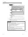
The functions that cannot be operated on GX Explorer are grayed (masked) and
cannot be selected. There are the following reasons why they are not selectable.
(1) The PLC CPU used does not have the functions
For example, "File register read specification" of "Upload from PLC" setting is
supported by A CPU only.
(2) The functions cannot be selected because they cannot be used with the
currently operated function
For example, all functions cannot be selected, while "PLC status monitor" dialog
box is open.
Refer to the manual to confirm if the function is supported by the PLC CPU used.
A-9
A-9
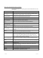
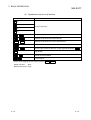
About Manuals
The following lists the manuals for this software package.
Refer to the following table when ordering manuals.
Related Manuals
Manual Number
(Model Code)
Manual Name
GX Developer Version8 Operating Manual
Explains the functions of the programing, printout, monitoring and debugging methods and so on GX
Developer.
(Sold separately.)
GX RemoteService-I Version2 Operating Manual
Explains setting, communicating and testing a personal computer by using GX RemoteService-I
Version2.
SH-080373
(13JU41)
SH-080465ENG
(13JU50)
(Sold separately)
Note:The Operating Manuals are included on the CD-ROM of the software package in a PDF file format.
Manuals in printed form are sold separately for single purchase. Order a manual by quoting the manual
number (model code) listed in the table above.
A - 10
A - 10
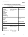
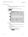
Generic Terms and Abbreviations Used in This Manual
Unless otherwise specified, the following generic terms and abbreviations are used
in this manual.
Generic Term/Abbreviation
GX Explorer
GX Developer
Description
Abbreviation of the GX Explorer Version 2 project management tool.
Generic product name of GX Developer Version 8 (product types SW8D5C-GPPW,
SW8D5C-GPPW-A, SW8D5C-GPPW-V, SW7D5C-GPPW-VA).
Generic term of the personal computers on which Windows 98/Me, Windows NT
R
Personal computer
DOS/V personal computer
Workstation 4.0 and Windows 2000 Professional operate.
R
IBM PC/AT or its compatible DOS/V personal computer.
PC CPU module
MELSEC-Q series compatible PC CPU module (CONTEC CO. LTD. make)
Basic model QCPU
Generic term for Q00JCPU, Q00CPU and Q01CPU
High Performance model
QCPU
Process CPU
MELSECNET/10(H)
CC-Link
R
Generic term for Q02 (H) CPU, Q06CPU, Q12HCPU and Q25HCPU
Generic term for Q12PHCPU and Q25PHCPU
Generic term of the MELSECNET/10 network system and MELSECNET/H network
system.
Abbreviation of the CC-Link (Control & Communication Link) system.
Generic term of the MELSEC-Q series PLC CPUs (Q00J, Q00, Q01, Q02(H), Q06H,
QPLC (Q mode)
Q12H, Q25H, Q12PH and Q25PH) and MELSECNET/H remote I/Os supported by GX
Developer.
QnAPLC
QPLC (A mode)
Generic term of the MELSEC-QnA series PLC CPUs (Q2A, Q2AS(H), Q2AS1,
Q2AS(H)S1, Q3A, Q4A, Q4AR) supported by GX Developer.
Generic term of the Q02(H)-A and Q06H-A.
Generic term of the MELSEC-A series PLC CPUs (A0J2H, A1FX, A1S, A1SJ, A1SH,
APLC
A1SJH, A1N, A2C, A2CJ, A2N(S1), A2N(S1), A2S, A2SH, A3N, A2A(S1), A3A,
A2U(S1), A2US(S1), A2AS(S1), A2AS-S30, A2AS-S60, A2USH-S1, A3U, A4U) and
motion controllers (SCPUs) supported by GX Developer.
Motion controller (SPLC)
FXPLC
Generic term of the A171SH(N), A172SH(N), A173UH(S1), A273UH(S3), Q172 and
Q173.
Generic term for PLC available with MELSEC-F
(The target PLCs are FX0, FX0S, FX0N, FX1, FX, FX2, FX2C, FX1S, FX1N, FX2N and FX2NC.)
AnNPLC
A1NCPU, A2NCPU(S1), A3NCPU
AnAPLC
A2ACPU(S1), A3A
AnUPLC
A2UCPU(S1), A2USCPU(S1), A2ASCPU(S1), A2ASCPU-S30, A2ASCPU-S60,
A2USHCPU-S1, A3U, A4U
A series
For GX Developer PLC type selection by ACPU
QnA series
For GX Developer PLC type selection by QnACPU
Q series
For GX Developer PLC type selection by QCPU (Q mode)
FX series
For GX Developer PLC type selection by FXCPU
A - 11
A - 11
Generic Term/Abbreviation
Computer link
Module
Description
For
A series
A1SJ71C24-R2, A1SJ71C24-R4, A1SJ71C24-PRF
A2CCPUC24(-PRF), A1SCPUC24-R2
For AnU
AJ71UC24, A1SJ71UC24-R2, A1SJ71UC24-R4, A1SJ71UC24-PRF
For
QnA eries
Generic term for AJ71QC24, AJ71QC24-R2, AJ71QC24-R4, AJ71QC24N,
A1SJ71QC24, A1SJ71QC24-R2, AJ71QC24N-R2, AJ71QC24N-R4, A1SJ71QC24N and
A1SJ71QC24N-R2
Serial
communication
Module
For
Q series
Generic term for QJ71C24 and QJ71C24-R2.
C24
Computer link Module, Serial Communication Module.
QE71
AJ71QE71(B5), A1SJ71QE71-B2, A1SJ71QE71-B5
E71
AJ71AJ71E71-S3, A1SJ71E71-B2-S3, A1SJ71E71-B5-S3
A1SJ71E71-B2, A1SJ71E71-B5, AJ71E71N-B2, AJ71E71N-B5T, A1SJ71E71N-B2,
A1SJ71E71N-B5T
Q series-compatible E71
Generic term for QJ71E71, QJ71E71-B2 and QJ71E71-100.
Ethernet module
Generic term for the AJ71E71-S3, A1SJ71E71-B2-S3, A1SJ71E71-B5-S3,
A1SJ71E71-B2, A1SJ71E71-B5, AJ71E71N-B2, AJ71E71N-B5T, A1SJ71E71N-B2,
A1SJ71E71N-B5T, AJ71QE71, AJ71QE71-B2, AJ71QE71-B5, A1SJ71QE71-B5,
QJ71E71, QJ71E71-B2, QJ71E71-100.
CC-Link module
Generic term for the AJ61BT11, A1SJ61BT11, AJ61QBT11, A1SJ61QBT11, QJ61BT11.
CC-Link bridge module
AJ65SBT-CLB CC-Link-CC-Link/LT bridge module.
G4 module
AJ65BT-G4(-S3) Peripheral Device Connection Module.
MELSECNET/10 board
Generic term for the A70BD-J71QLP23, A70BD-J71QLP23G, A70BD-J71QLR23,
A98BD-J71QLP23/ A70BD-J71BR13/ A98BD-J71QBR13 MELSECNET/10 interface
board.
MELSECNET/H board
Generic term for the Q80BD-J71BR11/ Q80BD-J71LP21-25/ Q80BD-J71LP21G
interface board.
Ethernet board
Generic term for Ethernet PC card/Ethernet interface board.
CC-Link board
A80BD-J61BT11/A80BD-J61BT13 CC-Link Interface board.
CPU board
A80BD-A2USH-S1 PLC CPU board.
A - 12
A - 12
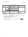
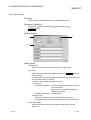
Product Makeup
GX Explorer is made up of the following products.
Type
Product Name
GX Explorer Version 2 (1-license product)
SW2D5C-EXP-E(V)
Quantity
(CD-ROM)
License agreement
1
End-user software license agreement
1
Method of installing the MELSOFT series
1
Software registration notice
1
INSTRUCTIONS ABOUT THE USAGE OF GX Explorer
1
GX Explorer Version 2 (Multiple license product)
(CD-ROM)
License agreement
SW2D5C- EXP-E(V)A
1
1
1
n*
End-user software license agreement
1
Method of installing the MELSOFT series
1
Software registration notice
1
INSTRUCTIONS ABOUT THE USAGE OF GX Explorer
1
*1: The number of included license agreements is equivalent to the number of licenses.
A - 13
A - 13
1 OVERVIEW
MELSOFT
1 OVERVIEW
1
This manual explains the system configuration, functions and operation of MELSEC
PLC-compatible maintenance tool, GX Explorer.
1.1 Features
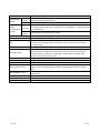
GX Explorer is the maintenance software package that includes functions required for
PLC system maintenance.
Wide rage of maintenance functions
GX Explorer (need to be connected to the target PLC system) always monitors
the operating status of PLC system at the production site and executes alarm
notification when an error occurs.
Furthermore, it includes following troubleshooting (error investigation and
recovery) functions, diagnostics, monitor, operation analysis and program
change (download to PLC).
Various connection routes
GX Explorer is compatible with various networks and can connect to the PLC
system at the production site through various connection routes. When making a
connection via the Internet, the remote production site can be maintained as the
same as on-site maintenance.
(When connecting this software package via the Internet, use of a personal
computer/Web server module (QJ71ES96) in which GX RemoteService-I is
installed as the server is required.)
Status Monitor
Operating
Status
Production
Site
Alarm Notification
Data
Collection
Planning
Maintenance
Alarm
Troubleshooting
Remote Maintenance
Inspection and
Confirmation
Recovery
Diagnostics
Monitor
Operation Analysis
Repair
Program modification
Device data correction
Module replacement
1-1
1-1
1 OVERVIEW
MELSOFT
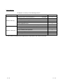
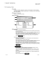
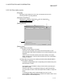
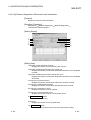
(1) Device monitor easier to see
--- Simultaneous monitor of multiple PLC CPUs ---
1
Without GX Explorer
Monitoring for each target PLC, each process.
It is required to register devices for each monitoring.
Process C
Packing
Process C
Process B
Manufacturing
Process B
Process A
Carry-in
Process A
How confusing, as
multiple monitor screens
are opened.
Device monitor screen
When using GX
Process C
Packing
Process B
Manufacturing
Explorer
By using device monitor
Simultaneous monitoring all processes
All processes can be simultaneously monitored.
Saving device registration
All Registered devices are usable/readable
for monitoring any number of times.
Process A
Carry-in
All processes can be
simultaneously monitored.
How convenient!
1-2
Device monitor screen
1-2
1 OVERVIEW
MELSOFT
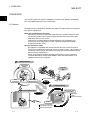
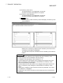
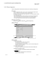
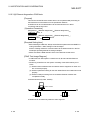
(2) Diagnostics function that notifies of error occurrence
--- Alarm details display --Process C
Without GX Explorer
It takes time to find where the error has occurred.
Packing
Process B
Manufacturing
Trouble has
occurred!
Process A
Carry-in
Ladder monitor screen
Where the error
has occurred?
When using GX
Explorer
By using alarm notification
The error section and cause are shown on the screen
Alarm details are notified in order to specify the error cause and take the corrective action.
Error diagnostics screen
Quicker to get
at the error cause!
Analysis screen
1-3
1-3
1 OVERVIEW
MELSOFT
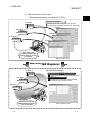
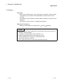
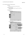
(3) Convenient project management
--- Upload from PLC/ Download to PLC --Without GX Explorer
The target PLC CPU must be changed for each Read from PLC/Write to PLC.
Process C
Packing
Process B
Manufacturing
Process A
Ladder screen
Carry-in
Read
from PLC screen
It is a hassle
to have to do many
key operations!
Transfer setup screen
When using GX
Explorer
By drag & drop
Simultaneous upload from/download to PLC of multiple programs
Multiple programs can be simultaneously upload from/download to multiple PLC CPUs.
Easier
operation !
Drag & drop
1-4
1-4
1 OVERVIEW
MELSOFT
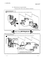
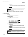
(4) Maintenance of remote location
--- Access to PLC CPU via the Internet or Intranet --Without GX Explorer
Without GX Explorer, the system in a remote location must be maintained on-site.
When using GX
Explorer
By remote maintenance
The system in a remote location can be maintained as the same as on-site maintenance.
GX Explorer
Version2
Server* 1
GX RemoteService-I
Version2
*1: The MELSOFT connection function of
@ GX RemoteService-I Version2 is required.
1-5
1-5
1 OVERVIEW
MELSOFT
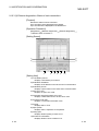
(5) Program operation can be virtually confirmed
Use of timing chart/ladder monitor enables the bit device status (ON/OFF) and
change of word device value can be virtually confirmed.
(6) Program backup and restore
The target data can be easily backed up or restored by drag & drop operation.
(7) File transfer by FTP
File transfer can be made between personal computers by FTP via the Intranet.
(8) Other convenient functions
--- Free customisation ---
GX Explorer can be freely customized for user-friendly operating environment.
Easy menu
Frequently-used functions can be easily selected without the necessity to
find them from the menu bar, as they can be displayed on "Easy menu"
dialog box.
For details, refer to Section 11.1.1 (2).
Target name specification
Target PLC CPU and the connection route can be saved as any name. By
specifying the PLC CPU name, the target PLC CPU can be easily changed.
For details, refer to Section 8.2.
Access data name
Devices to be monitored can be grouped and saved as any name. This
setting is applicable for the "Device monitor" and "Timing chart" settings.
For details, refer to Section 8.3.
User setting name
Operating environment settings can be saved as any name according to
various applications.
Read out the saved operating environment by specifying the corresponding
name.
For details, refer to Section 5.1.1 (1) and Section 6.1 to 6.5.
(For information on applicable data, refer to the table "Data that can be
saved in the user setting name" of Section 6.4 "Saving the User Setting
Name As")
(9) Various applicable devices
Extension file register, buffer memory of all PLC CPU types can be directly seen.
POINT
• For details on extension file register and buffer memory compatible with GX
Explorer, refer to Appendix 3.
1-6
1-6
2 SYSTEM CONFIGURATION
MELSOFT
2 SYSTEM CONFIGURATION
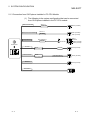
2.1 System Configuration
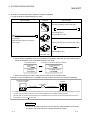
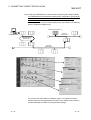
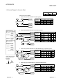
2.1.1 Connection from the Serial/USB Port
2
The following system configuration is made up by connection from the serial port.
*1
USB cable
USB communication
QCPU (Q mode)
*2
Converter/cable
FXCPU
(FX0/FX0S/FX1S/FX0N/FX1N
FX2N/FX1NC/FX2NC)
*2
Converter/cable
*5
*3
QC30R2
QCPU (Q mode)
QCPU (A mode)
*4
Converter/cable
Serial port communication
ACPU
QnACPU
*4
Converter/cable
GX Explorer
FXCPU
(FX0/FX0S/FX1/FX1S/FX0/FX2
FX2C/FX1N /FX2N/FX1NC/FX2NC)
*4
Converter/cable
*6
cable
*7
Computer link
*5
FXCPU
(FX1S/FX1N/FX2N)
*6
FXCPU
(FX1S/FX1N/FX2N/FX1NC/FX2NC)
See Appendix-5
RS-232
C24
CC-Link (via G4)
*4
Converter/cable
CC-Link
G4 module
G4-S3 module
MELSECNET(II)
FXCPU
(FX1S/FX1N/FX2N)
ACPU
QnACPU
QCPU (Q mode)
QCPU (A mode)
ACPU
QnACPU
QCPU (Q mode)
QCPU (A mode)
*4
Converter/cable
Remote station
Remote unit
Master station
Remote station
Remote unit
Control station
MELSECNET/10
MELSECNET/H
2-1
*4
Converter/cable
2-1
2 SYSTEM CONFIGURATION
MELSOFT
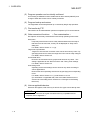
*1: About the USB cable (QCPU (Q mode) compatible)
1) Usable when Windows 98 and USB driver have been installed.
2) Unusable for Windows NT , Workstation 4.0.
3) Use of the USB cable allows only one PLC CPU to be connected.
4) Use the USB cable which conforms to the USB Standard Rev. 1.1.
5) When using a USB cable for communication, note the following precautions and restrictions.
• Do not communicate the PLC CPU while any of the following personal computer functions, Resume
function, Suspend setting, Power saving function, Standby mode is ON, as this may cause a
communication error.
Make sure to communicate with the PLC CPU without these settings.
• Do not frequently perform the following operations during communication with PLC CPU: removal of
USB cable, reset of PLC CPU and power-ON/PFF, as this may cause a communication error and the
communication may not recovered from the error.
Therefore, make sure not to perform the GX Explorer online operation* when performing any of the
above operations.
If the communication is not recovered, completely pull the USB cable. Then five seconds later,
reinsert the cable. (After this action is taken, the communication error will occur when the first
attempt to communicate is made. However, if it occurs once, the error will not occur at the second
and later attempts.)
* Online operation: Execution of the functions included in the menu bar, [Confirm], [Operation] and
[Diagnostics].
• A communication error may occur depending on the combination of personal computer module and
USB cable, etc.
In this case, follow the provided message.
R
R
B
PW
SD
RD
FX-USB-AW
FX
(RS-422)
MITSUBISHI
*2 About the converter/cable (FXCPU compatible)
1) System configuration
FX-USB-AW
USB cable (Included with product)
2) Usable when Windows 98, Windows Me, Windows 2000 Professional, Windows XP Professional or
Windows XP Home edition and the driver included in the CD-ROM have been installed.
3) Unusable for Windows 95, Windows NT Workstation 4.0.
4) Refer to Section 8.1, for serial COM port number setting.
R
R
R
R
R
R
R
*3: About the cable (QCPU (Q mode), QCPU (A mode) compatible)
For communication in 115.2/57.6 kbps
Fast communication cannnot be made if the Personal computer used is not compatible with the
communication speed of 115.2/57.6 kbps.
If a communication error occurs, reduce the baud rate etting and restart communication.
The following cable has been confirmed by Mitsubishi Electric that it will work properly.
Using the cable of Mitsubishi Electric make.
RS-232 cable
QC30R2 (when Personal computer connector is D-sub, 9-pin)
2-2
2-2
2
2 SYSTEM CONFIGURATION
MELSOFT
*4: About the converter/cable (ACPU, QnACPU, FXCPU compatible)
1) Using the products of Mitsubishi Electric make
Personal computer Side
(RS-232 cable)
RS-232/RS-422
Converter
PLC CPU Side
(RS-422 cable)
For ACPU, QnACPU, FX1/FX2/FX2CCPU
FX-232AW
FX-422CAB (0.3m)
FX-422CAB-150 (1.5m)
F2-232CAB-1
(when Personal computer connector is
D-sub, 9-pin)
FX-232AWC
FX-232AWC-H
For FX0/FX0S/FX0N/FX1S/FX1N/FX2N/FX2NCCPU
FX-422CABO (1.5m)
(FX series only)
• How to identify compatibility of the F2-232CAB and F2-232CAB-1 cables with the ACPU and QnACPU
Check the indication of the model label attached to the cable.
Incompatible products
Compatible products(with indication of F/FX/A)
F2-232CAB
Y990C
F2-232CAB(F/FX/A)
Y990C
F2-232CAB-1
Y990C
F2-232CAB-1(F/FX/A)
Y990C
• When connecting to FX series, make sure to use the device in the above table.
Example of connecting IBM-PC/AT-compatible personal computer and QnA CPU using EX-232AW(C)
IBM PC/AT-campatible
personal computer
QnACPU
FX-232AW(C)
*1
F2-232CAB-1
FX-422CAB(-150)
*1: A straight cable (connector) for converting between D sub 9 pin and D sub 25 pin might be required, depending on the cable.
Use the conversion cable by referring to the manual of the IBM-PC/AT-compatible personal computer.
(RS-232 cable for connection between IBM-PC/AT-compatible personal computer and converter mentioned in the above)
F2-232CAB-1 (D sub 9 pin
D sub 25 pin)
REMARK
Access can be made to the PLC CPU through GOT-F900 (instead of a converter).
For details, refer to the manual or catalog of the above product.
2-3
2-3
2 SYSTEM CONFIGURATION
MELSOFT
*5: Function expansion board
Series
Function expansion board
FX2N
FX2N-422-BD
FX1S, FX1N
FX1N-422-BD
POINT
When using a function expansion board, PLC parameters must be set using GX
Developer.
For details, refer to "System configuration" provided in GX Developer operating
manual.
*6: RS-232 cable and function expantion board (special adapter)
Shape of serial port
for personal computer
Series
Required function expansion board
and special adapter
FX0N-232ADP+FX2N-CNV-BD
FX2N
FX2N-232-BD
FX2NC-232ADP+FX2N-CNV-BD
D sub 9 pin
FX1NC, FX2NC
FX1S, FX1N
FX2NC-232ADP
FX-232CAB-1
FX0N-232ADP+FX1N-CNV-BD
F2-232CAB-1
FX1N-232-BD
FX2N-232-BD
FX2NC-232ADP+FX2N-CNV-BD
FX1NC, FX2NC
FX1S, FX1N
FX-232CAB-1
F2-232CAB-1
FX0N-232ADP+FX2N-CNV-BD
S sub 25 pin
F2-232CAB-1
FX0N-232ADP
FX2NC-232ADP+FX1N-CNV-BD
FX2N
RS-232 cable
FX-232CAB-1
F2-232CAB
F2-232CAB-1
FX0N-232ADP
F2-232CAB
FX2NC-232ADP
F2-232CAB-1
FX0N-232ADP+FX1N-CNV-BD
F2-232CAB
FX1N-232-BD
FX2NC-232ADP+FX1N-CNV-BD
F2-232CAB-1
POINT
When using a function expansion board, PLC parameters must be set using GX
Developer.
For details, refer to "System configuration".
*7: Computer link
When going through a computer link module to ACPU, the programs including V, X (indexing) cannot be
monitored.
2-4
2-4
2 SYSTEM CONFIGURATION
MELSOFT
POINT
• When using a function expansion board, PLC parameters must be set using GX
Developer.
For details, refer to "System configuration" provided in GX Developer operating
manual.
• Before handling the RS-422 interface conversion cable/converter, please read its
specifications, precautions, etc. carefully in the manual of the corresponding
product and handle it correctly.
• When disconnecting or reconnecting the conversion cable/converter that
receives 5VDC power from the RS-422 interface, switch power off on the PLC
CPU side before starting work.
• When disconnecting or reconnecting the peripheral device or conversion cable
that does not receive 5VDC power from the RS-422 interface (whose power is
supplied from an external power supply), be sure to use an earth band or touch a
grounded metal object, etc. before starting work to discharge static electricity
from the cable, human body, etc. After that, handle it in the following procedure.
1) Switch power off on the personal computer side.
2) Power off the conversion cable/converter. When it has an FG terminal,
ground it.
3) Connect/disconnect the conversion cable/converter between the personal
computer and PLC CPU.
4) Power on the conversion cable/converter.
5) Power on the personal computer.
6) Start up the software package.
2-5
2-5
2 SYSTEM CONFIGURATION
MELSOFT
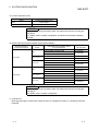
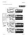
2.1.2 Connection from the Interface Boards
The following system configuration is made up by connection from the interface boards.
Refer to the corresponding board manuals for the way to connect the boards and
install the drivers.
MELSECNET/10 board
A70BDE-J71QLP23
(Optical loop)
A70BDE-J71QLP23GE
(Optical loop)
A70BDE-J71QBR13
(Coaxial bus)
A70BDE-J71QLR23
(Coaxial loop)
Driver
SW3DNF-MNET10
ACPU
QnACPU
QCPU (Q mode)
QCPU (A mode)
Other station PLC
MELSECNET/H board
GX Explorer
Q80BD-J71BR11
(Coaxial bus)
Q80BD-J71LP21-25
(Optical loop)
Q80BD-J71LP21G
(Optical loop)
Q80BD-J71LP21GE
(Optical loop)
Driver
SW0DNC-MNETH-B
Other station PLC
CC-Link board
Driver
A80BDE-J61BT13
A80BDE-J61BT11
ACPU
QnACPU
QCPU (Q mode)
QCPU (A mode)
SW4DNF-CCLINK-B
ACPU
QnACPU
QCPU (Q mode)
QCPU (A mode)
Other station PLC
Ethernet board
Commercially available
Ethernet board
Driver
Driver supplied with
commercially available
Ethernet board
ACPU
QnACPU
QCPU (Q mode)
QCPU (A mode)
Other station PLC
CPU board
Driver
A80BDE-A2USH-S1
2-6
SW1DNF-ANU-B
2-6
2 SYSTEM CONFIGURATION
MELSOFT
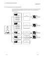
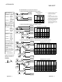
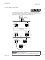
2.1.3 Connection from GX Explorer Installed in PC CPU Module
(1) The following is the system configuration that can be connected
from GX Explorer installed in the PC CPU module.
See 2.1.1
USB cable
USB communication
Serial port communication
Computer link
QCPU (Q mode)
See 2.1.1
QC30R2
QCPU (Q mode)
QCPU (A mode)
See Appendix-5
RS-232
C24
ACPU
QnACPU
QCPU (Q mode)
QCPU (A mode)
GX Explorer
CC-Link
MELSECNET/H
Ethernet
Driver
PPC-DRV-01
CC-Link
Driver
PPC-DRV-01
MELSECNET/H
QCPU (Q mode)
QCPU (Q mode)
QCPU (Q mode)
Q Sries Bus
Multiple CPU
2-7
2-7
2 SYSTEM CONFIGURATION
MELSOFT
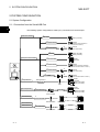
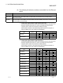
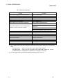
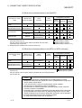
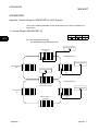
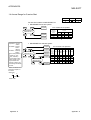
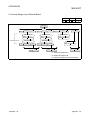
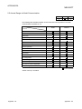
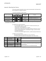
2.1.4 System Equipment Lists
(1) The following list indicates module connectable from the serial port.
PLC Series
Module Name
MELSECNET(II) data link remote I/O module
MELSECNET/B data link remote I/O module
MELSECNET/10 network remote I/O module
G4 module
PLC CPU module
Module Model
Q00J, Q00, Q01, Q02(H), Q06H, Q12H, Q12PH,
Q25H, Q25PH
Q02(H)-A, Q06H-A
QJ71C24, QJ71C24-R2, QJ71C24N, QJ71C24N-R2,
QJ71C24N-R4
QJ72LP25, QJ72BR15
AJ65BT-G4-S3
Q2A, Q2AS(H), Q2AS1, Q2AS(H)S1, Q3A, Q4A, Q4AR
AJ71QC24, AJ71QC24-R2, AJ71QC24-R4,
AJ71QC24N, A1SJ71QC24, A1SJ71QC24-R2,
AJ71QC24N-R2, AJ71QC24N-R4, A1SJ71QC24N,
A1SJ71QC24N-R2
AJ72QLP25, AJ72QBR15, A1SJ72QLP25,
A1SJ72QBR15, QJ72LP25, QJ72BR15
AJ65BT-G4, AJ65BT-G4-S3
A0J2H, A1S(S1), A1FX, A1SJ, A1SH, A1SJH, A1N,
A2C, A2CJ, A2N(S1), A2S(S1), A2SH(S1), A3N,
A2A(S1), A3A, A2U(S1), A2US(S1), A2AS(S1), A2ASS30, A2AS-S60, A2USH-S1, A3U, A4U
AJ71UC24, A1SJ71UC24-R2, A1SJ71UC24-PRF,
A1SJ71C24-R2, A1SJ71C24-PRF, A1SCPUC24-R2,
A2CCPUC24, A2CCPUC24-PRF, A1SJ71UC24-R4
AJ72P25, AJ72R25
AJ72T25B, A1SJ72T25B
AJ72LP25, AJ72LP25, AJ72BR15
AJ65BT-G4, AJ65BT-G4-S3
FX0(S), FX0N, FX1, FX2(C), FX1S, FX1N, FX2N(C)
PLC CPU module
A171SH, A172SH, A173UH(S1), A273UH(S3)
PLC CPU module
Q series
Serial communication module 1
MELSECNET/H network remote I/O module
G4-S3 module
PLC CPU module
Serial communication module 2
QnA series
MELSECNET/10 network remote I/O
module
G4 module
PLC CPU module
A series
FX series
MOTION
(SCPU)
Computer link module 3
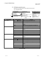
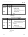
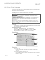
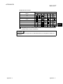
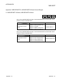
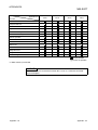
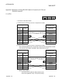
(2) The following table indicates the modules which can be connected
from the MELSECNET/10 or MELSECNET/H (MELSECNET/10
mode) board.
PLC Series
Q series
QnA series
A series
Module Name
QJ71LP21, QJ71LP21G, QJ71BR11, QJ71LP21-25, QJ71LP21S-25
AJ71QLP21, AJ71QBR11, A1SJ71QLP21, A1SJ71QBR11
AJ71LP21, AJ71BR11, A1SJ71LP21, A1SJ71BR11
(3) The following table indicates the modules which can be connected
from the MELSECNET/H board.
PLC Series
Q series
Module Name
QJ71LP21, QJ71BR11, QJ71LP21-25
(4) The following list indicates modules connectable from the CC-Link
board.
PLC Series
Q series
QnA series
A series
2-8
Module Name
QJ61BT11, QJ61BT11N
AJ61QBT11, A1SJ61QBT11
AJ61BT11, A1SJ61BT11
2-8
2 SYSTEM CONFIGURATION
MELSOFT
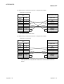
(5) The following list indicates modules connectable from the Ethernet
board.
PLC Series
Q series
QnA series
A series
Module Name
QJ71E71, QJ71E71-B2, QJ71E71-100, QJ71E71-B5
AJ71QE71, AJ71QE71-B5, A1SJ71QE71-B2, A1SJ71QE71-B5, AJ71QE71N-T, A1SJ71QE71N-T,
AJ71QE71N-B5, A1SJ71QE71N-B5, AJ71QE71N-B2, A1SJ71QE71N-B2, AJ71QE71N-B5T,
A1SJ71QE71N-B5T
AJ71E71-S3, A1SJ71E71-B2-S3, A1SJ71E71-B5-S3, A1SJ71E71-B2, A1SJ71E71-B5,
AJ71E71N-B2, AJ71E71N-B5T, A1SJ71E71N-B2, A1SJ71E71N-B5N, AJ71E71N-T, A1SJ71E71N-T,
AJ71E71N-B5, A1SJ71E71N-B5
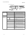
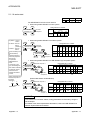
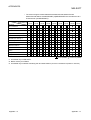
*1: Via the serial communication module (QCPU (Q mode))
The following table indicates whether the interfaces may be connected to the
personal computer when the PLC CPU is accessed from the personal
computer via the serial communication module (Q series).
If the module cannot be connected directly with the personal computer, it
may be usable as the "n"th module of multidropping.
Type
QJ71C24
QJ71C24-R2
Interface
1:1
Connection
Multidropping
First module
"n"th module
RS-232
RS-422/485
RS-232
RS-232
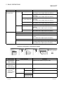
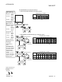
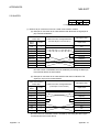
*2: Via the serial communication module (QnACPU)
The following table indicates whether the interfaces may be connected to the
personal computer when the PLC CPU is accessed from the personal
computer via the serial communication module (QC24).
If the module cannot be connected directly with the personal computer, it
may be usable as the "n"th module of multidropping.
Type
AJ71QC24
AJ71QC24N
AJ71QC24-R2
AJ71QC24N-R2
AJ71QC24-R4
AJ71QC24N-R4
A1SJ71QC24
A1SJ71QC24N
A1SJ71QC24-R2
A1SJ71QC24N-R2
2-9
Interface
1:1
Connection
Multidropping
First module
"n"th module
RS-232
RS-422/485
RS-232
RS-422/485
RS-232
RS-232
RS-232
RS-232
RS-422
RS-422/485
RS-422
RS-422/485
RS-232
RS-422/485
RS-232
RS-422/485
RS-232
RS-232
RS-232
RS-232
2-9
2 SYSTEM CONFIGURATION
MELSOFT
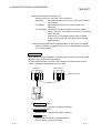
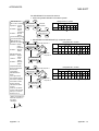
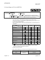
*3: Via the computer link module
About the computer link module
Note that when the PLC CPU is accessed from the personal computer via the
computer link module, the modules that may be connected directly with the
personal computer are limited.
If the module cannot be connected directly with the personal computer, it
may be usable as the "n"th module of 1:n connection.
Type
AJ71UC24
AJ71C24-S6
AJ71C24-S8
A1SJ71UC24-R2
A1SJ71C24-R2
A1SJ71UC24-PRF
A1SJ71C24-PRF
A1SJ71UC24-R4
A1SJ71C24-R4
A1SCPUC24-R2
A2CCPUC24
A2CCPUUC24-PRF
2 - 10
Interface
1:1
Connection
1:n Connection
First module
"n"th module
RS-232
RS-422/485
RS-232
RS-422
RS-232
RS-422
RS-232
RS-232
RS-232
RS-232
RS-422/485
RS-422/485
RS-232
RS-232
RS-422
RS-422/485
RS-232
RS-422
RS-422/485
2 - 10
2 SYSTEM CONFIGURATION
MELSOFT
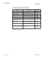
2.2 Operating Environment
The following is the operating environment of GX Explorer.
Item
Description
R
Computer
200MHz or more (recommended) Pentium personal computer on
which Windows operates
Operating System
Microsoft
Microsoft
Microsoft
Microsoft
Microsoft
Microsoft
R
Necessary memory
Free hard disk area
R
R
R
R
R
R
R
Windows 98 operating system
Windows Me operating system
1
Windows NT Workstation 4.0 operating system*
1
Windows 2000 Professional operating system*
1
Windows XP Professional operating system*
1
Windows XP Home Edition operating system*
R
R
R
R
R
64MB or more recommended
For installation
130MB or more
For operation
100MB or more
Disk drive
CD-ROM disk drive
Display resolution
1024
Required software
(Required only when
combined with GX
RemoteService-I Version2.)
For personal
computer CPU
For Web
server module
768 dots or more (XGA or more)
Web server
Personal Web Server version4 or later
Internet Information Server version5 or later
Peer Web Services verision4 or later
Web browser
Internet Explorer5.5 or later
Netscape4.5 or later
Mailer
Not specified
Java execution
environment (JavaVM)
Microsoft JavaVM of Build No. 3309 or later
Web browser
Internet Explorer5.5
Internet Explorer6.0
Mailer
Not specified
*1: Administrator privilege is required to install GX Explorer into the following operating systems, WindowsNT
Workstation4.0, Windows 2000 Professional, Windows XP Professional and Windows XP Home Edition.
In addition, Administrator privilege is required to use GX Explorer in Windows XP Professional and
Windows XP Home Edition.
R
R
R
R
R
R
POINT
• Instruction for use of the online manual
Addition of memory ensures more comfortable use.
• Instruction for use of the PDF data
Use with addition of personal computer memory ensures comfortable operation.
2 - 11
2 - 11
2 SYSTEM CONFIGURATION
MELSOFT
POINT
• Permission of access to folders and files
Use of this product may change the files within the installation destination folder
and sub folders.
Therefore, the user must be granted write access to these folders and files, if
either of the following operating systems is used.
Without this setting, product may not operate correctly.
Microsoft Windows XP Professional
Microsoft Windows XP Home Edition
Microsoft Windows 2000 Professional
Microsoft Windows NT Workstation 4.0
It is recommended to log on as an administrators group user, who is granted to
control the computer, to use this product.
• New functions of Windows XP
Note that this product may not operate correctly when any of the following new
functions of Microsoft Windows XP Professional and Microsoft Windows XP
Home Edition is used, as they are unsupported.
Compatibility mode (The application supported by earlier version of
Windows is run using this mode.)
Fast user switching
Remote desktop
Desktop themes change (Larger font is selected.)
• Personal computer setting for MELSOFT connection
When terminating the access to the PLC CPU through MELSFOT connection, it
may take time until the MELSFOT connection screen is closed. In this case,
consult with the personal computer administrator and take either of the following
actions, as this may close the screen in a shorter time.
R
R
R
R
R
R
R
R
R
R
R
R
R
(Action 1)
Close the most unnecessary one among the running application software.
(Action 2)
Make the settings in order to increase the virtual memory of personal computer
according to the following procedure.
[Procedure]….In the case of Microsoft Windows 2000 Professional
(1) Select "System" in the control panel.
(2) The system property screen appears.
R
R
Click Performance options within <<Advanced>>.
(3) The performance options screen appears.
Click Change of "Virtual memory".
(4) The virtual memory screen appears.
Change the "Initial size" and "Maximum size" to larger value.
(5) Click on Set button.
After the settings are made, the virtual memory of personal computer is
increased.
2 - 12
2 - 12
3 MAIN FUNCTIONS
MELSOFT
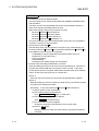
3 MAIN FUNCTIONS
The following explains functions for "Monitor", "Investigation/Confirmation" and
"Recovery", and other useful functions.
Monitor................................... Always monitors system status using alarm notification,
error diagnostics or other functions
Investigation/Confirmation .... Investigates/Confirms system status using diagnostics,
monitor, analysis or similar functions.
Recovery ............................... Performs program change (download to PLC), device
data change and others.
3
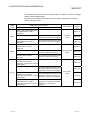
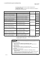
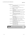
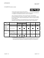
(1) Useful functions for monitoring
Function
Monitor
Description
Reference
Alarm notification
Notifies of error occurrence and the analysis, diagnostics results
by e-mail.
Section 9.12
Error diagnostics
Displays the error of the target PLC CPU based on the error
condition defined by the user.
Section 9.7
PLC diagnostics
Executes the diagnostics of the target PLC CPU.
Section 9.9
Analysis
Executes the analysis of the target PLC CPU operation (order
check, count check, failure (normal/faulty) check, high/low limit
value check) and displays the analysis results.
Section 9.8
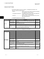
(2) Useful functions for investigation/confirmation
Function
Description
Reference
PLC status monitor
Displays the PLC CPU operation status and program list.
Section 9.1
Device monitor
Simultaneously monitors devices for multiple PLC CPUs.
Section 9.2
Timing chart
Displays the timing chart of the specified device.
Section 9.3
Trace
Executes sampling trace for the specified device.
Section 9.4
Ladder monitor
Investigates the ON/OFF cause for ladder monitor and device.
Section 9.5
PLC diagnostics
Diagnoses the target PLC CPU.
Section 9.9
Network diagnostics Diagnoses MELSECNET/H, CC-Link, Ethernet or other networks. Section 9.10
Investigation
/Confirmation
3-1
System monitor
Display the system configuration, each module error status and
history.
Section 9.11
Alarm notification
Notifies of error occurrence and the analysis, diagnostics results
by e-mail.
Section 9.12
Error diagnostics
Displays the error of the target PLC CPU based on the error
condition defined by the user.
Section 9.7
Analysis
Executes the analysis of the target PLC CPU operation (order
check, count check, failure (normal/faulty) check, high/low limit
value check) and displays the analysis results.
Section 9.8
Device test
Tests the specified device. (Simultaneous test of all specified
devices.)
Section 10.2
3-1
3 MAIN FUNCTIONS
MELSOFT
(3) Useful functions for recovery
Function
Description
Upload from
PLC/Download to PLC
Recovery
Reference
Reads/Writes project data (Maintenance)
Chapter 7
FTP site
Reads project data via the FTP site
Section 7.13.
Replacing module online
(Hot swapping)
Replaces a module without stopping the system when the module
Section 9.11.1
is faulty.
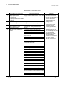
(4) Other useful functions
Function
File operation
Project
operation
Connection
target
specifications
Tool
3-2
Description
Reference
Imports/Exports access data name, operation analysis, Error
diagnostics name or other data.
Section 6.6
FTP site
Reads from/Writes to files through the FTP site connection.
Section 7.1.3
PLC batch
operation
Multiple project data can be simultaneously uploaded
from/downloaded to multiple PLC CPUs. This function is
available by relating target PLCs and projects by name in
advance.
Section 7.8
Relating a target
name and a project
Relates target PLCs and projects by name. This setting is useful
for "PLC batch operation".
Section 7.9
Backup
Backs up data of specified projects.
Section 7.15
Restore
Restores backed up projects.
Section 7.16
Backup
arrangement
Deletes the project specified from the backed up projects.
Section 7.17
Network
configuration
analysis
specification
Specify the analysis target, i.e., network that includes the
connection target station.
Section 8.1
Connection Target
Name
Saves the PLC CPU to be accessed and the path as name.
Section 8.2
Access data name
Groups devices to save the group as any name.
Section 8.3
MELSOFT
connection
Internet/Intranet settings.
Section 8.4
Easy menu
Registers frequently-used functions to execute them by using one
Section 11.1.1
button.
Option
Changes the settings for project display, network configuration
information and online change.
Section 11.1.2
Security setting
Settings for illegal access prevention
Section 11.1.3
Operation log
Collects and saves the operation history including start of this
product to operation termination.
Section 11.1.4
Auto-start setting
Settings for auto start of this product or specified functions at the
start of personal computer.
Section 11.1.5
Import/Export
3-2
3
4 INSTALLATION AND UNINSTALLATION
MELSOFT
4 INSTALLATION AND UNINSTALLATION
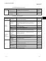
This chapter describes the installation and uninstallation of this product.
4.1 Installation
This section explains the installation procedure and operation of this product.
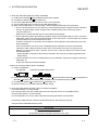
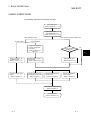
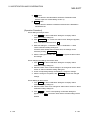
(1) Installation procedure
Install this product in the following procedure.
New installation
4
Version upgrade
Install the product.
Register the Name and Company.
Register the product ID.
Select the installation destination.
Refer to
Section 4.1.
Boot the application.
Check whether the product has been
installed properly.
Refer to
Section 5.1.1 (1).
Refer to the manual of the previous version.
Install the product.
Register the Name and Company.
Refer to
Register the product ID.
Section 4.1.
Install the product ID of the previous version.
Select the installation destination.
Boot the application.
Check whether the product has been
installed properly.
Complete
Uninstall the
previous version.
Refer to
Section 5.1.1 (1).
Complete
POINT
• When a message appears to confirm if each DLL will be overwritten at the time of
installation, Click Yes button to execute the overwrite of DLL. If DLL is not
overwritten, the product may not be executed correctly.
• When using upgraded version (SW2D5C-EXP-JV or later) of the product, make
sure to uninstall the older version (SW1D5C-EXP-J).
If the older version is not uninstalled, unnecessary data will remain.
4-1
4-1
4 INSTALLATION AND UNINSTALLATION
MELSOFT
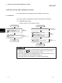
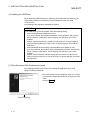
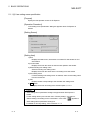
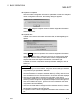
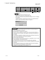
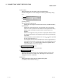
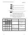
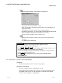
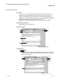
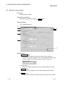
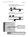
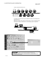
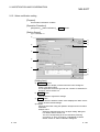
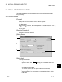
(2) Installation of this product
Check the following before starting installation.
POINT
• Before starting installation, close all other applications that are running on
Windows .
• When using Windows NT Workstation 4.0 or Windows 2000 Professional, log
on as a user who has the attributes of an administrator (for computer
management).
R
R
R
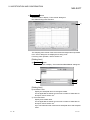
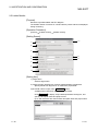
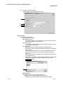
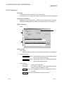
Installing the product (The screen is that of Windows 2000.)
R
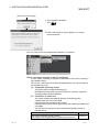
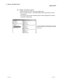
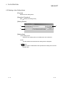
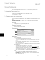
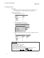
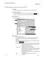
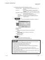
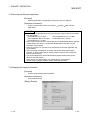
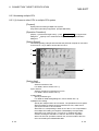
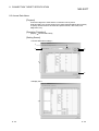
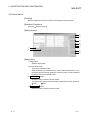
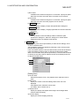
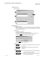
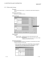
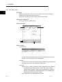
1) Boot Windows Explorer and click the drive where
the disk is inserted.
Double-click "Setup.exe".
In the case of Windows 2000 Professional, rightclick [Start] and select [Explorer].
R
R
Double-click here.
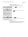
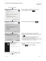
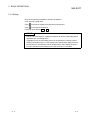
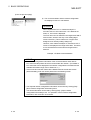
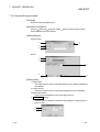
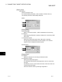
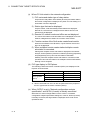
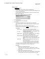
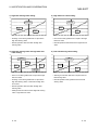
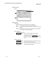
2) If either of the following messages appears, perform
operation as shown below.
If the left screen appears, perform operation
according to the instruction (a) given in "When a
message appears at start of installation".
If the left screen appears, perform operation
according to the instruction (b) given in "When a
message appears at start of installation".
If the left screen appears, perform operation
according to the instruction (c) given in "When a
message appears at start of installation".
If the left screen appears, perform operation
according to the instruction (d) given in "When a
message appears at start of installation".
(To the next page)
4-2
4-2
4
4 INSTALLATION AND UNINSTALLATION
MELSOFT
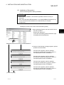
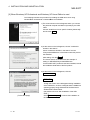
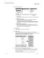
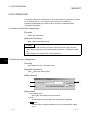
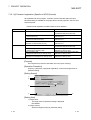
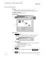
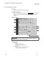
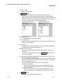
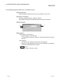
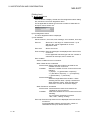
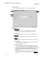
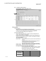
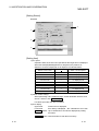
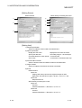
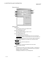
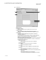
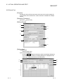
(From the previous page)
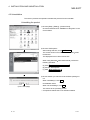
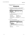
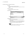
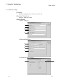
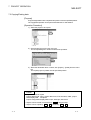
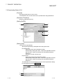
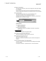
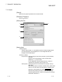
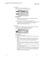
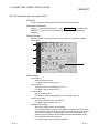
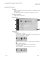
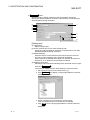
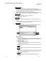
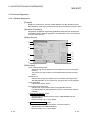
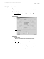
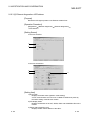
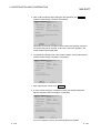
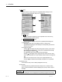
3) Type the name and company, and click Next> .
As the confirmation dialog box appears, follow the
message and perform operation.
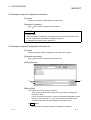
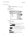
4) Enter the product ID and click Next> .
The product ID is described on the "License agreement"
included in the product.
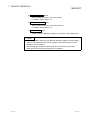
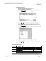
5) The left screen is for version upgrade.
Enter the product ID of the older version and click Next> .
The product ID is described on the "Software Registration
Card" or "License agreement" included in the older
product.
When newly installing the product, the following screen will
not appear.
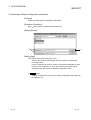
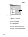
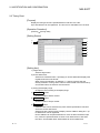
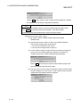
6) Specify the installation destination folder.
Click Next> if the destination folder displayed is OK.
To change the folder, click Browse and specify a new
drive and folder.
(To the next page)
4-3
4-3
4 INSTALLATION AND UNINSTALLATION
MELSOFT
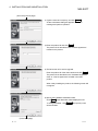
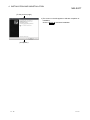
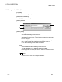
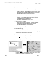
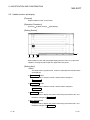
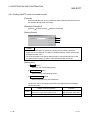
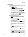
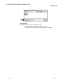
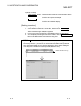
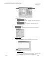
(From the previous page)
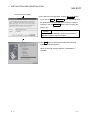
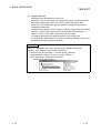
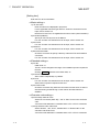
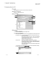
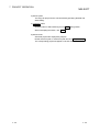
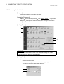
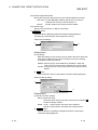
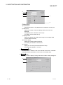
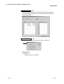
7) This completes installation.
Click OK .
8) If the screen shown on the left appears, you need to
reboot Windows .
R
The icon of the product is registered after installation is completed.
When a message appears at start of installation
In some cases, a message may appear at installation of the product, resulting in
the installation failure.
If this occurs, make sure to close all running applications, and carry out either of
the operations (a) to (d).
(a) Supported operating system
The product does not support Windows 95.
Reinstall the product into the personal computer in which the supported
operating system has been installed.
R
(b) Installation of Axdist.exe
This section explains the updating operation of Windows using
"Update\Axdist.exe" on the CD-ROM.
Execute Axdist.exe provided for this product.
Install this product after executing the exe file and restarting the IBM-PC/AT
compatible.
The exe file to be executed on the corresponding operating system is
indicated below.
R
Supportrd operating system
Microsoft Windows 98 Operating System
Microsoft Windows NT Workstation Operating System Version 4.0
R
R
File name
R
R
Axdist.exe
(Axdist.exe are in the "Update" folder on CD-ROM.)
4-4
4-4
4 INSTALLATION AND UNINSTALLATION
MELSOFT
(c) Installation of 50comupd.exe
This section explains the updating operation of Windows using
"Update\50comupd.exe" on the CD-ROM.
R
1) Click the Yes button to start updating Windows.
2) Accept the agreement on the left screen and click the
Yes button.
3) Click Yes to restart.
After a restart, perform the installation operation in (2) 1).
(d) Installation of EnvMEL
Execute Setup.exe in the "EnvMEL" folder on this product CD-ROM.
Install this product after executing the "Setup exe". If this product is not
installed properly at this time, reboot the personal computer.
4-5
4-5
4 INSTALLATION AND UNINSTALLATION
MELSOFT
4.2 Uninstallation
This section provides the operation to delete this product from the hard disk.
Uninstalling the product
1) Choose [Start] - [Setting] - [Control Panel].
Choose and double-click "Add/Remove Programs" in the
Control Panel.
2) Choose "GX Explorer".
After making selection, click Add/Remove .
The screen shown on the left is that of Windows 2000
Profeeional.
The displayed screen varies with the OS.
R
When using Windows 2000 Professional, perform the
following operation.
R
(a) Click Change or Remove Programs .
(b) Choose "GX Explorer".
(c) Click Change/Remove .
3) Check whether you will romove the software package or
not.
When uninstalling it, click Yes .
Uninstallation starts.
(To the next page)
When not uninstalling it, click No .
This returns to the preceding screen.
* Components indicate the icons and files installed.
4-6
4-6
4 INSTALLATION AND UNINSTALLATION
MELSOFT
(From the previous page)
4) If the left screen has appeared, click the No To All button.
If you click the Yes or Yes To All button, the shared file of
the Windows compatible MELSOFT product is removed.
R
Therefore, click the No To All button when removing this
product only.
POINT
If files common to MELSOFT products are deleted, a
MELSOFT product may be unusable.
5) Click OK when the message indicating that removing
operation is finished appears.
When the finished message appears, uninstallation is
complete.
4-7
4-7
4 INSTALLATION AND UNINSTALLATION
MELSOFT
4.3 Installing the USB Driver
When Windows 2000 Professional, Windows XP Professional and Windows XP
Home Edition is used, the USB driver must be installed to make CPU USB
communication.
The following is the USB driver installation procedure.
R
R
R
POINT
If the USB driver cannot be installed, check the following setting.
• When Windows 2000 Professional is used
If you have selected "Block-Prevent installation of unsigned files" after [Control
Panel] - [System] - [Hardware] - [Driver Signing], the USB driver may not be
installed.
Choose "Ignore-Install all files, regardless of file signature" or "Warn-Display a
message before installing an unsigned file" for [Driver Signing], and install the
USB driver.
• When Windows XP Professional or Windows XP Home Edition is used
If you have selected "Block-Never install unsigned driver software" after [Control
Panel] - [System] - [Hardware] - [Driver Signing], the USB driver may not be
installed.
Choose "Ignore-Install the software anyway and don't ask for my approval" or
"Warn-Prompt me each time to choose an action" for [Driver Signing], and install
the USB driver.
R
R
R
[1] When Windows 2000 Professional is used
R
The following indicates the procedure for installing the USB driver when using
Windows 2000 Professional.
R
1) The screen shown on the left appears when you connect
the personal computer and QCPU (Q mode) by the USB
cable.
Click the Next> .
(To the next page)
4-8
4-8
4 INSTALLATION AND UNINSTALLATION
MELSOFT
(To the previous page)
2) Choose "Search for a suitable driver for my device
(recommended)" and click the Next> .
3) Check "Specify a location" and click the Next> .
4) As the screen on the left appears, set this product
installation destination "Easysocket\USBdrivers" and click
the OK .
The screen shown on the left shows the example of
setting C:\MELSEC\Easysocket\USBdrivers.
If volume MELSOFT products have been installed, browse
the installation destination of the first product.
5) The screen on the left appears to indicate completion of
installation.
Click the Finish to terminate installation.
(Completion)
4-9
4-9
4 INSTALLATION AND UNINSTALLATION
MELSOFT
[2] When Windows XP Professional and Windows XP Home Edition is used
R
R
The following indicates the procedure for installing the USB driver when using
Windows XP Professional or Windows XP Home Edition.
R
R
1) The screen shown on the left appears when you connect
the personal computer and QCPU (Q mode) by the USB
cable.
Choose "Install from a list or specific location [Advanced]"
and click the Next> .
2) As the screen on the left appears, choose "Include this
location in the search".
Check "Include this location in the search" and set
"Easysocket\USBDrivers" of the folder where this product
was installed.
After setting, click the Next> .
The screen shown on the left shows the example of
setting C: \MELSEC\Easysocket\USBDrivers.
If volume MELSOFT products have been installed, browse
the installation destination of the first product.
3) As the screen on the left appears, click the
Continue Anyway .
REMARK
Though the screen on the left appears during installation
of the USB driver, we have confirmed that the USB driver
operates properly using Windows XP Professional or
Windows XP Home Edition.
(No problem will occur after installation of the USB
driver.)
R
R
(To the next page)
Click Continue Anyway to continue the installation of
the USB driver.
4 - 10
4 - 10
4 INSTALLATION AND UNINSTALLATION
MELSOFT
(To the previous page)
4) The screen on the left appears to indicate completion of
installation.
Click the Finish to terminate installation.
(Completion)
4 - 11
4 - 11
5 BASIC OPERATIONS
MELSOFT
5 BASIC OPERATIONS
The following outlines the GX Explorer operation.
Start GX Explorer.
(Refer to Section 5.1. 1. (1).)
User setting name
specification dialog box.
(Refer to Section 5.1. 1. (2).)
When creating a project.
PC side window
When performing system maintenance.
PLC side window
Analysis and update of
network configuration
information.
(Refer to Section 5.5.1
and 5.5.3.)
Yes
Has the target name
already set?
5
No
Display a project on the
PC side window.
(Refer to Section 5.4.1.)
Display data on the PLC
side window.
(Refer to Section 5.5.2.)
Operate a project within
the PC.
(Refer to Chapter 7.)
Operate and recover the
data within the PLC CPU.
(Refer to Chapter 7.)
Set the target name.
(Refer to Section 8.2.)
Diagnose the data within
the PLC CPU.
(Refer to Chapter 9.)
Monitor the data within
the PLC CPU.
(Refer to Chapter 9.)
Save the user setting name.
(Refer to Chapter 6.)
Exit GX Explorer.
(Refer to Section 5.1.2.)
5-1
5-1
5 BASIC OPERATIONS
MELSOFT
5.1 Starting and Exiting
5.1.1(1) Starting
The following is a sequence of operations for starting GX Explorer.
When "Select existing user setting name"
is selected.
When "New" is selected.
5
When "Last end state"
is selected.
The screen appears the same as
when the last operation was ended.
The initial screen appears that does not
include saved data, PC side window or
PLC side window.
The screen appears the same as the
user setting name was saved.
POINT
• "User setting name specification" dialog box appears when GX Explorer is
started.
When selecting "Last end state" or "Select existing user setting name" on the
dialog box, a dialog box appears to confirm if the network configuration
information will be updated, if GX Explorer was ended with PLC side window
open at the previous operation.
Select OK to analyze the new network configuration and update the
information.
Select Cancel to display the previous information.
If the previous network configuration information has not been previously set,
"Not yet retrieved" will be displayed
5-2
5-2
5 BASIC OPERATIONS
MELSOFT
5.1.1 (2) User setting name specification
[Purpose]
Specify the first operation screen of GX Explorer.
[Operation Procedure]
"User setting name specification" dialog box appears when GX Explorer is
started.
[Setting Screen]
[Setting Item]
1) New
Displays the initial screen, which does not include PC side window or PLC
side window.
2) Last end state
Displays the screen the same as when the last operation was ended.
3) Select existing user setting name
Select an existing user setting name.
Displays the screen the same as the user setting name was saved.
4) User setting name
If "Select existing user setting name" is selected, select a user setting name
from the combo box.
5) Title
Displays the title corresponding to the selected user setting name.
6) OK button
Displays the screen according to the selected option 1, 2 or 3.
POINT
• "User setting name specification" dialog box appears when GX Explorer is
started.
If "User setting name input" has been set in "Security setting", only option 3,
"Select existing user setting name" is selectable. In this case, "
" appears in
"User setting name specification" dialog box.
For details of "Security setting", refer to Section 11.1.3.
5-3
5-3
5 BASIC OPERATIONS
MELSOFT
5.1.2 Exiting
There are the following methods to exit from GX Explorer.
• Click the [File] - [Exit] menu.
• Click
on the left of the title bar and click the [Close] menu.
• Click
on the right of the title bar.
• Press the shortcut keys Alt + F4 .
POINT
• Prior to end of GX Explorer, a dialog box appears to confirm if the setting will be
registered as a user setting name.
If registered once, the user setting name can be selected by checking "Select
existing user setting name" in "User setting name specification" dialog box from
the next time on; the operation can be started with the same setting as saved.
For each operation of user setting name, refer to Section 6.1 and later.
5-4
5-4
5 BASIC OPERATIONS
MELSOFT
5.2 Screen Layout
5.2.1 Screen layout
The following shows the screen layout and common operations of GX Explorer.
(1) Screen layout
This section explains the screen layout and common operations of GX Explorer.
Title bar
Menu bar
Tool bar
(d) Easy menu
(a) PC side window
(b) PLC side
window
(c) Status bar
(a) PC side window
Project display field
Detail display field
Project configuration display field
• Project display field
Drives, folders, projects and files within a personal computer are
displayed in tree format.
• Detail display field
When a drive or folder is selected in Project display field, objects
(folders, projects or files) within the selected drive or folder are
displayed.
• Project configuration display field
Data within a project are displayed in tree format.
This is relevant only when category data (data type and data name)
are displayed in Detail display field.
5-5
5-5
5 BASIC OPERATIONS
MELSOFT
(b) PLC side window
PLC display field
Device detail display field
Memory configuration
display field
• PLC display field
The network configuration of the connected station is displayed in tree
format.
• Device detail display field
When a network type is selected in PLC display field, stations
connected to the selected network are displayed.
When a station is selected in PLC display field, the memory (drive)
configuration and stored data of the selected station are displayed in
tree format.
• Memory configuration display field
Data within the selected PLC CPU are displayed in tree format.
This is relevant only when category data (data type and data name)
are displayed in Device detail display field.
(c) Status bar
GX Explorer status information is displayed.
(d) Easy menu
Frequently-used functions can be set as Easy menu. This setting
eliminates the time to find the target function from tool bar or menu bar, and
enables each function to be started by using one button.
For details of Easy menu, refer to Section 11.1.1 (2).
(e) Other function window display examples
Each function window is displayed when the PLC system is maintained.
In this section, timing chart and ladder monitor execution window are
displayed as examples.
For details of maintenance function, refer to Chapter 9 and 10.
5-6
5-6
5 BASIC OPERATIONS
MELSOFT
(2) Common operation
Purpose
Operation
Switch between displaying and hiding the toolbar.
[View] – [Toolbar] menu
Switch between displaying and hiding the status bar.
[View] – [Status bar] menu
Moves the selected item up one layer.
[View] – [Move up] menu
Displays the target data in list format.
[View] – [List] menu
1
Displays details of the target data.*
[View] – [Details] menu
Displays details of the project data configuration.
[View] – [Project configuration] menu
[View] – [Icon arrangement] – [Name order] menu
Arranges the displayed items when displaying the
project list or system configuration diagram.
[View] – [Icon arrangement] – [Type order/Station number
order] menu
[View] – [Icon arrangement] – [Size order] menu
[View] – [Icon arrangement] – [Date order] menu
2
Updates the information.*
[View] – [Refresh] menu
Open the PC side window.
[Window] – [Open PC side window] menu
Open the PLC side window.
[Window] – [Open PLC side window] menu
Immediately accesses the specified function.
[Window] – [Open easy menu] menu
Close the active window.
[Window] – [Close] menu
Close all open windows.
[Window] – [All Close] menu
Display the windows one over another partially.
[Window] – [Cascade] menu
Display the windows side by side.
[Window] – [Tile Vertically] menu
Display the windows top to bottom.
[Window] – [Tile Horizontally] menu
*1: When details of the target data is displayed, the following items appear depending on the selected
object.
PC side window:
Name, PLC type, Size, Type, Update date, Attributes
PLC side window: Name, PLC type, Connection route, Network No., Station No., PLC No.
Available attributes: R (Read only), H (Hidden file), S (System), A (Archive)
*2: The information will be automatically updated by displaying other layer, too.
5-7
5-7
5 BASIC OPERATIONS
MELSOFT
5.2.2 Menu list
(1) GX Explorer drop-down menus
Menu
File
New user setting name
Project
Description
Item
User setting name-relevant operations.
Button
Reference
Section 6.1
Open user setting name
Section 6.2
Save user setting name
Section 6.3
Save user setting name as
Section 6.4
Delete user setting name
Section 6.5
Import/Export
Reads/Writes setting data of each function.
Section 6.6
Open network configuration
information
Save network configuration
information
Save network configuration
information as
Delete network configuration
information
Exit
Network configuration information-relevant
operations.
Section 6.7
Exits GX Explorer.
New
System data
Displays the system data creation screen.
Section 7.1.1
Folder
Creates a new folder.
Section 7.1.2
FTP site
Displays the FTP server connection setting screen.
Section 7.1.3
Cut
Places the target data on the clipboard.
Section 7.2
Copy
Copies the target data onto the clipboard.
Section 7.3
Paste
Pastes the data from the clipboard.
Section 7.2
Select all
Selects all displayed items.
Section 7.4
Upload from PLC
Displays the setting screen for "Upload from PLC".
Section 7.5
Download to PLC
Displays the setting screen for "Download to PLC".
Section 7.6
Section 6.8
Section 6.9
Section 6.10
PLC data deletion
Deletes the specified data within the target PLC
CPU.
PLC batch operation
Displays the batch operation screen for data within
the PLC CPU.
Inter-connect Target name and
Displays the screen for relating the target PLC and
Project
project.
Keyword
Keyword registration Displays the screen for registering a keyword and
password.
Keyword delete
Displays the screen for deleting a keyword and
password.
Search
Displays the setting screen for project search.
Consistency check
---
Section 7.7
Section 7.8
Section 7.9
Section 7.10.1
Section 7.10.2
Section 7.11
Rename
Displays setting screen for checking the consistency
of projects, parameters and comments.
Renames the project.
Delete
Deletes the project.
Section 7.14
Backup
Backs up the target data.
Section 7.15
Restore
Displays the restore screen.
Section 7.16
Section 7.12
Section 7.13
(To the next page)
5-8
5-8
5 BASIC OPERATIONS
MELSOFT
(From the previous page)
Menu
Project
View
Description
Item
Backup arrangement
Displays backup data in list format.
Section 7.17
Run relevant application
Start the corresponding MELSOFT applications.
Section 7.18
Property
Displays the property information.
Section 7.19
Toolbar
Displays the customize setting screen for toolbar.
Status bar
Selects whether status bar will be displayed or not.
Move up
Moves the cursor up one layer.
List
Displays the target data in list format.
Details
Displays details of the target data.
Project configuration
Displays details of the project data.
Arranges the displayed items when displaying the
Icon
Name order
arrangement Type order/Station project list or system configuration diagram.
number order
Size order
Button
Reference
Section 5.2.1
Date order
Object
Refresh
In the case of PC side window, the file information
is updated.
In the case of PLC side window, the network
configuration information is updated.
Network configuration analysis
specification
Connection Target name
Displays the screen for specifying the analysis
target, i.e., network configuration.
Displays the setting screen for target PLC and
connection route.
Displays the setting screen for access data name.
Access data name
Confirm
Connect to MELSOFT
Displays the setting screen for connecting to GX
RemoteService-I via the Internet or Intranet.
PLC Status monitor
Displays the screen for monitoring the PLC CPU
status.
Displays the screen for executing a device monitor.
Device monitor
Timing chart
Trace
Ladder
monitor
Ladder monitor
Split display
Split display cancel
Displays the screen that provides a timing chart of
the specified device.
Displays the screen for trace execution.
Section 8.2
Section 8.3
Section 8.4
Section 9.1
Section 9.2
Section 9.3
Section 9.4
Displays the screen for specifying the ladder
monitor target.
Splits the ladder monitor screen.
Device search
Restores the split ladder monitor screen to a single
pane.
Searches for the specified device.
Step No. search
Searches for the step No./block No..
ON/OFF cause find.
Searches for the device that does not turn
ON/OFF.
Displays the screen for registering a local device
monitor.
Local device monitor setting
Section 8.1
Section 9.5
Section 9.6
(To the next page)
5-9
5-9
5 BASIC OPERATIONS
MELSOFT
(From the previous page)
Menu
Operation
Item
Remote operation
Device test
Diagnostics Error diagnostics
Operation analysis
PLC diagnostics
Network
Network diagnostics
diagnostics
CC-Link diagnostics
Ethernet diagnostics
System monitor
Alarm notification
Tool
Customize
Toolbar
Displays the screen for operating a PLC
system in a remote location.
Displays the screen for executing a device
test.
Displays the screen for executing an error
diagnostics.
Displays the screen for executing an
operation analysis.
Displays the screen for executing a PLC
diagnostics.
Displays the screen for executing a
MELSECNET diagnostics.
Displays the screen for executing a CC-Link /
CC-Link/LT diagnostics.
Displays the screen for executing an Ethernet
diagnostics.
Displays the screen for executing a system
monitor.
Displays the screen for executing an alarm
notification.
Button
Reference
Section 10.1
Section 10.2
Section 9.7
Section 9.8
Section 9.9
Section 9.10
Section 9.11
Section 9.12
Displays the customize screen for each
function.
Section 11.1.1
Option
Displays the option setting screen.
Section 11.1.2
Security setting
Displays the security setting screen.
Section 11.1.3
Operation log
Displays the operation log setting screen.
Section 11.1.4
Auto-start setting
Displays the auto-start setting screen.
Section 11.1.5
Open PC side window
Displays the PC side window.
Open PLC side window
Displays the PLC side window.
Open Easy menu
Displays the Easy menu.
Close
Each function window-relevant display
operation.
Easy menu
Window
Description
Close all
Section 5.2
Cascade windows
Tile windows vertically
Tile windows horizontally
Help
5 - 10
Help
Displays the GX Explorer Help.
Key operation list
Displays the shortcut key list.
CPU error
Displays the PLC CPU error code list.
Special relay/Register
Displays the special relay/special register list.
Product information
Displays the product information.
Connect to MELFANS web
Connects to MELFANS web.
Section 11.2
5 - 10
5 BASIC OPERATIONS
MELSOFT
(2) GX Explorer right-click menu
Right-click menus differ with the cursor position as shown below
(a) PC side window
Project display field
Detail display field
4)
1)
Project configuration display field
5)
6)
9)
2)
3)
7)
8)
Cursor position
1) Drive name
2) System data
3) FTP site
4) Folder
Function displayed
New
Search
Copy
Paste
System data
Backup
Property
Search
Copy
Paste
Delete
Rename
Backup
Property
Search
Copy
Paste
Delete
Property
New
Search
Cut
Copy
Paste
Delete
Rename
Backup
Property
System data
Description
Displays the system data creation screen.
Searches for a project.
Copies the target data onto the clipboard.
Pastes the data from the clipboard onto the specified
position.
Backs up the project data within the specified drive.
Displays the drive property.
Searches for a project.
Copies the target data onto the clipboard.
Pastes the data from the clipboard onto the specified
position.
Deletes the target folder.
Renames the folder.
Backs up the project data within the specified folder.
Displays the folder property.
Searches for a project.
Copies the target data onto the clipboard.
Pastes the data from the clipboard onto the specified
position.
Deletes the target FTP site.
Displays the FTP site property.
Displays the system data creation screen.
Searches for a project.
Places the target data on the clipboard.
Copies the target data onto the clipboard.
Pastes the data from the clipboard onto the specified
position.
Deletes the target folder.
Renames the folder.
Backs up the project data within the specified folder.
Displays the folder property.
(To the next page)
5 - 11
5 - 11
5 BASIC OPERATIONS
MELSOFT
(From the previous page)
Cursor position
5) Multiple general-purpose
file names/multiple folder
names/multiple project
names
Cut
Function displayed
Description
Places the target data on the clipboard.
Copy
Copies the target data onto the clipboard.
Delete
Deletes the target file.
Back up
Backs up the project data within the specified folder.
6) Project name
Run relevant application
7) General-purpose file
name
Starts the corresponding application.
(Not available when "All station project" is selected.)
View
Displays details of the target project data configuration.
(Available only when a project name is selected in the
detail display field.)
Project
configuration
Cut
Places the target data on the clipboard.
(Available only when any project within "All station project"
is selected)
Copy
Copies the target data onto the clipboard.
Paste
Pastes the data from the clipboard onto the specified
position.
(Not available when a general-purpose file name is
selected.)
Delete
Deletes the target file.
(Not available when any project within "All station project"
is selected.)
Rename
Renames the file.
(Not available when any project within "All station project"
is selected.)
Back up
Backs up the project including the specified folder.
(Available only when a project is selected.)
Property
8) Blank area within the
detail display field
Displays the file property.
New
Folder
Creates a new folder
View
List
Displays the data within the detail display field in list
format.
Details
Displays details of the data within the detail display field.
Name order
Icon
arrangement Type order/
Station number
order
Arranges the data within the detail display field.
Size order
Date order
9) Data name displayed in
tree format within the
project configuration
display field
5 - 12
Paste
Pastes the data from the clipboard onto the specified
position within the detail display field.
Property
Displays the property of the inverted item (selected data).
Run relevant application
Starts the corresponding application.
For data name, the corresponding data will be displayed.
Copy
Copies the target data onto the clipboard.
Paste
Pastes the data from the clipboard onto the specified
position.
(Not available when multiple data are selected.)
5 - 12
5 BASIC OPERATIONS
MELSOFT
(b) PLC side window
PLC display field
Device detail display field
Memory configuration display field
1)
5)
2)
3)
Cursor position
Function displayed
4)
Description
Refresh
Updates the network configuration information.
(Not available when a network name is selected.)
Copy
Copies the target data onto the clipboard.
Paste
Pastes the data from the clipboard onto the specified
position.
2) Target name (Root Paste
directory/folder)
Pastes the data from the clipboard onto the specified
position.
3) PLC name
Run relevant application
Starts the corresponding application to display the data.
(Not available when multiple objects are selected.)
View
Displays details of the target project data configuration.
(Not available when multiple objects are selected/in the
PLC display field.)
1) PLC, Network
name
4) Target name
5 - 13
Project configuration
Refresh
Updates the data within the target PLC CPU.
(Not available when multiple objects are selected.)
Copy
Copies the target data onto the clipboard.
Paste
Pastes the data from the clipboard onto the specified
position.
(Not available when multiple objects are selected.)
PLC data deletion
Deletes the target data.
(Not available when multiple objects are selected.)
Target name
Starts the target specification screen while the target PLC
CPU is selected. (Not available when multiple objects are
selected.)
Device monitor
Starts the screen for executing a device monitor of the
target PLC CPU.
(Not available when multiple objects are selected.)
Timing chart
Starts the screen for executing a timing chart of the target
PLC CPU.
(Not available when multiple objects are selected.)
5 - 13
5 BASIC OPERATIONS
Cursor position
3) PLC name
4) Target name
MELSOFT
Function displayed
Diagnostics PLC diagnostics
Keyword
5) Data name
Description
Displays the screen for executing a PLC diagnostics.
(Not available when multiple objects are selected.)
Network diagnostics
Displays the screen for executing a MELSECNET
diagnostics.
(Not available when multiple objects are selected.)
CC-Link diagnostics/
CC-Link/Lt diagnostics
Displays the screen for executing a CC-Link / CC-Link/LT
diagnostics.
(Not available when multiple objects are selected.)
Ethernet diagnostics
Displays the screen for executing an Ethernet diagnostics.
(Not available when multiple objects are selected.)
System monitor
Displays the screen for executing a system monitor.
Keyword registration
Displays the screen for registering a keyword and
password.
(Not available when multiple objects are selected.)
Keyword delete
Displays the screen for deleting a keyword and password.
(Not available when multiple objects are selected.)
Run relevant application
Starts the corresponding application to display the data.
Copy
Copies the target data onto the clipboard.
Paste
Pastes the data from the clipboard onto the specified
position.
(Not available when multiple objects are selected.)
PLC data deletion
Deletes the target data.
Ladder monitor
Available only when a data name is specified for starting
the ladder monitor setting screen for the target PLC CPU.
(Not available when multiple objects are selected.)
Network configuration information display
6)
Cursor position
7)
Function displayed
Refresh
6) Not yet retrieved
(When a target
name is selected.)
7) Not yet retrieved
(When a PLC
route is selected.)
Refresh
8) Blank area within
the device detail
display field
(When a network
is selected.)
View
Icon arrangement
8)
Description
Updates the data within the target PLC CPU.
Updates the network configuration information.
List
Displays the data within the device detail display field in list
format.
Details
Displays details of the data within the device detail display
field.
Name order
Arranges the data within the device detail display field.
Type order/
Station No. order
5 - 14
5 - 14
5 BASIC OPERATIONS
MELSOFT
(c) Others
1)
2)
3)
Cursor position
1) Toolbar
Toolbar
Description
Displays the customize setting for toolbar.
2) Framework
(grayed section)
Open PC side window
Displays the PC side window.
Open PLC side window
Displays the PLC side window.
3) Ladder monitor
Split display
Splits the ladder monitor screen.
Split display cancel
Restores the split ladder monitor screen to a single pane.
Device search
Searches for the specified device.
Step No. search
Searches for the step No./block No.
Device test
Displays the screen for executing a device test.
ON/OFF cause find.
Searches for the device that does not turn ON/OFF.
Available for device specification during ladder display.
5 - 15
Function displayed
5 - 15
5 BASIC OPERATIONS
MELSOFT
5.2.3 Icon lists
The following lists icons on GX Explorer.
(1) PC side window
Icon
Description
Reference
Local drive
---
Network drive
---
FTP site
---
CD-ROM drive
---
Removal media (e.g. FD, MO) drive
---
Folder
---
System data
---
Network configuration information not yet retrieved
---
PLC name (PLC side window)
---
Target name list (PLC side window)
---
PLC CPU, Remote I/O station
---
MELSECNET/10(H)
---
CC-Link
---
QCPU:
Program memory/Device memory
A/QnA/FXCPU: Internal RAM/Device memory
QCPU:
Memory card (RAM)
QnACPU:
IC memory card A (RAM), IC memory card B (RAM)
QCPU:
Memory card (ROM)
QnACPU:
IC memory card A (ROM), IC memory card B (ROM)
-------
QCPU:
Standard RAM
---
QCPU:
Standard ROM
---
Import/Export data
Section 6.6
Snapshot data
Section 9.2
Timing chart diagram
Section 9.3
Trace data
Section 9.4
Network configuration information
Section 8.1
(To the next page)
5 - 16
5 - 16
5 BASIC OPERATIONS
MELSOFT
(From the previous page)
Icon
Description
Parent folder for all station upload (Color: Pale bule)
---
GX Developer project data (Gppw. wps, Gppw. wpj)
(Color: Green)
---
GX Configurator-QP project data
---
Sequence program (***.wpg)
---
Sequence program (for password setting)
---
SFC program (***.wps)
---
PLC parameter (Param.wpa), Network parameter, Remote
password (Param.wpa)
---
Intelligent module parameter (Iparam.wpa)
---
Common comment (Common.wcd)
---
Common comment (for password setting)
---
Comment for respective program (***.wcd)
---
Comment for respective program (for password setting)
---
Device memory (***.wdv)
(Color: White)
Device initial value (***.wdi)
(Color: Pale blue)
5 - 17
Reference
-----
Device initial value (for password setting)
---
Other data (general-purpose data)
---
Global variable
---
File register (***.wdr)
---
GX Configurator-CC User data (***.cmp, ***.com, ***.crp)
---
GT Designer2 project data (***.gtd)
---
PX Developer project data (***.fpj)
---
5 - 17
5 BASIC OPERATIONS
MELSOFT
5.2.4 Shortcut key lists
(1) Project list/Network configuration information
Operation
Description
+ key
Opens the currently selected folder.
- key
Closes the currently selected folder.
key
Opens the selected folder when it is closed.
Selects a folder right under the selected folder when it is open.
key
Closes the selected folder when it is open.
Selects the right overhead layer when the selected folder is closed.
Backspace
Moves to the layer above the current one.
Ctrl + A
Selects all objects within the right window.
Ctrl + X
Cuts specified items.
Ctrl + C
Copies specified items.
Ctrl + V
Pastes specified items.
Ctrl + drag
Performs "Download to PLC", i.e., writes to PLC side window from PC side
window.
Performs "Upload from PLC", i.e., read from PLC side window to PC side
window.
Copies objects.
Shift + drag
Performs "Download to PLC", i.e., writes to PLC side window from PC side
window.
Performs "Upload from PLC", i.e., read from PLC side window to PC side
window.
Shifts objects.
Alt + Enter
Displays the property for the specified item.
Delete or Shift + Delete
Deletes selected objects from the disk.
F5
Updates the window data.
5 - 18
5 - 18
5 BASIC OPERATIONS
MELSOFT
(2) Operations common to all screens
Operation
Description
key
key
Moves through items.
key
key
Alt or F10
Makes the menu bar active.
Alt + Space
Displays the shortcut menu of the title bar.
Shift or F10
Displays the shortcut menu of the specified item.
Tab
Moves to the next active item.
Shift + Tab
Moves to the previous active item. (in the opposite direction to Tab )
F1
Help display
Ctrl + F4
Closes the active window.
Alt + F4
Exit GX Explorer.
* Action when dragging the item without pressing Ctrl / Shift .
Within one drive:
Shift
Between two drives: Copy
5 - 19
5 - 19
5 BASIC OPERATIONS
MELSOFT
5.3 Text input (Applicable character type and max. number of characters)
The following explains the text input for GX Explorer, i.e., applicable character type and
max. number of characters.
Setting item
Applicable character type
Max. number of characters
User setting name
Target name
Access data name
Operation log name
Data name (Import/Export)
Device list name
Trace name
Alarm name
Error diagnostics name
Analysis name
System data name
FTP site name
All station project name
Snap shot data name
Timing chart diagram name
Case-insensitive
All characters other than followings:
• Punctuation character (11 types) *1
• Characters inapplicable for folder name
(space at the top, dot)
• Reserved words *1
32 characters.
(For project names, refer to the
specifications of the corresponding
package.)
Password (Security setting)
Alphanumeric character*2
32 characters
Title (All functions)
No restrictions
32 characters
Alarm notification
• SMTP, POP3 server name
• E-mail address
• User name
• Password
• Destination e-mail address
No restrictions
255 characters
(256 characters for SMTP, POP3
server name)
FTP site setting
• Host name (Address)
• User name, password
• Account
• Initial folder name
No restrictions
80 characters
(220 characters for initial folder
name)
Internet connection setting
• Host name
• Address
No restrictions
Wildcard
All characters other than punctuation
characters *1
(However, "*" and "?" are applicable)
150 characters
Program name
Device memory name
Device data name
Device comment name
No restrictions
8 characters
Drive/Path name*3
Search place
Restore destination folder name
All characters other than punctuation
characters *1
(However, "\" and ":" are applicable)
150 characters
64 characters
256 characters
(To the next page)
5 - 20
5 - 20
5 BASIC OPERATIONS
MELSOFT
(From the previous page)
Setting item
Device name
Device value
16/32 bit
integer
Applicable character type
Max. number of characters
Case-insensitive
Alphanumeric character (Applicable to
existing device names only)
18 characters
Dec
Numeric character (0 to 9)
"-" is applicable to the head position only.
Depending on the data type
Hex
Numeric character (0 to 9)
Alphabet (A to F)
Real number
Numeric character (0 to 9), ".", "E", "+", "-"
ASCII character
No restrictions
Error diagnostics
• Error message
• Error help
No restrictions
64 characters
800 characters
*1: Punctuation character
Reserved word
*2: Alphanumeric character
(\ / : ; , *?“ < > |)
(CON AUX COM1 to COM9 LPT1 to LPT9 PRN NUL)
(a to z, A to Z, 0 to 9)
Space ! “ # $ % & ‘ ( ) * + , - / : ; < = > ? @ [\] ^_ ` { | }
*3: When using either of the following methods to specify the drive name/path name on the screen, make sure
to add "/" to the last of the path name/system data name.
(1) Directly entering a user-specified drive name/path name arbitrarily
(2) Entering a system data name
Alternatively, select the drive name/path name from the options (provided by clicking Reference button),
and "•" will be automatically added.
5 - 21
5 - 21
5 BASIC OPERATIONS
MELSOFT
5.4 Operations for PC Side Window
5.4.1 Displaying the data in the personal computer
This section explains the basic operations to be performed in the PC side window.
Click [Window]- [Open PC side window] to display the PC side window.
(1) Viewing the objects in the drive or folder
Choosing a drive or folder in the project display field or double-clicking a folder in
Select a drive or folder in the project display field to display the corresponding
content in the detail display field. Alternatively, perform the following operation
while keeping a driver or folder selected.
Double-click or press + or
key.
The content of the selected driver or folder will be displayed.
Press * key.
The content of the layer beneath the selected drive or folder will be displayed in
the project display field.
Objects included within a system data,
"Manufacturing data", will be displayed.
(2) Viewing the project layout
Perform the following operations to view the project configuration.
• Select a project in the project display field.
• Select a project in the detail display field and click [View] – [Project
configuration].
Category data (data type and data name) of the selected project will be
displayed in the project configuration display field.
The project configuration of
"Manufacturing line_A1000"
will be displayed in the project
configuration display field
Select a project, e.g.,
"AProcessing line_A1000"
POINT
Note that when folders and files in the personal computer are displayed, GX
®
Explorer may differ from Windows Explorer in icons and/or upper/lower-case
character indications.
5 - 22
5 - 22
5 BASIC OPERATIONS
MELSOFT
(3) Display "All station project".
• Select "All station project" in the project display field.
• Select "All station project" in the detail display field and click [View] – [Project
configuration].
The content of the selected "All station project" will be displayed in the project
configuration display field.
Project configuration of "Manufacturing line control"
("All station project") within the project configuration
display field.
5 - 23
5 - 23
5 BASIC OPERATIONS
MELSOFT
5.5 Operations for PLC Side Window
5.5.1 Displaying the PLC configuration information
If there is no network configuration information at an initial start or like, display the
connection stations and network configuration in the PLC side window in the following
procedure.
(1) Operation sequence
1) Click [Object] – [Network configuration analysis
specification].
2) Select the PLC series of the target PLC CPU in "PLC
Series selection" dialog box.
3) Make the settings of "PC side I/F", "PLC side I/F" and
others in "Network configuration analysis specification"
dialog box and click OK . (For details of "Network
configuration analysis specification" dialog box, refer to
Section 8.1.)
4) A dialog box appears to confirm if the network
configuration information will be updated.
Clicking OK will update the information.
Clicking Cancel will not update the information and
display the previous information.
If the previous network configuration information has not
been previously set, "Not yet retrieved" will be displayed
in the PLC side window device detail display field.
For details of "Option setting", refer to Section 11.1.2.
5) When the network configuration information is updated,
the corresponding confirmation dialog box appears.
(To the next page)
5 - 24
5 - 24
5 BASIC OPERATIONS
MELSOFT
(From the previous page)
6) The connected station and the network configuration
are displayed in the PLC side window.
REMARK
When "Upload from PLC" or "Network analysis" is
executed, the PLC CPU name with "<S>" added to the
head, i.e., PLC name is displayed.
The PLC name can be selected in the target name field of
each function, similar to the way a user setting target
name is selected. (This is irrelevant to "Target name"
dialog box and "Security setting" dialog box.)
However, when "Network analysis" is executed, the PLC
name is not displayed in the target name filed. Therefore,
it is recommended to set the name as target name in
advance.
Example: <S>Q06H connected station
POINT
• The network configuration information of the connected station varies with its
PLC series and the position where it is located within the network. (For details of
PLC series that can be displayed in the network configuration information and the
available information range, refer to Section 8.1.1.)
• If the connection has been made via the QCPU Ethernet module with remote
password setting, enter the remote password in the following screen.
• The acquired network configuration information can be saved by clicking [File] –
[Save network configuration information] menu.
The saved information can be read by clicking [File] – [Open network
configuration information] menu. For operation of each network configuration
information, refer to Section 6.7 and later.
5 - 25
5 - 25
5 BASIC OPERATIONS
MELSOFT
5.5.2 Displaying the data in the PLC CPU
This section describes the display operation to be performed in the PLC side window.
(1) Network configuration
Select [Window] – [Open PLC side window] form the menu bar to display the
PLC side window.
After a dialog box appears to confirm if the network configuration information will
be updated, display the PLC network configuration.
The PLC configuration field shows the connection station and the station names
connected to MELSECNET/10(H) and CC-Link in a tree structure.
Station that is specified to analyze the network configuration.
Indicates MELSECNET/H, MELSECNET/10 of network No. 1.
Shows the configuration of MELSECNET/10,
MELSECNET/10 (network No. 1).
Indicates the first CC-Link module on the normal station
(station No. 2) of network No. 1.
Shows the configuration of CC-Link (first module).
The station names are displayed as indicated below.
• For the connection station, the PLC type and station type are displayed.
(Example)
<S> Q06H Connection station
PLC type
Station type
• For CC-Link on the connection station, the PLC type, module number, station
type and station number are displayed.
The module number indicates the master/local module number on the
connection station.
The station number is given to the local station only.
(Example)
<S> Q06H (board1) Local station No.1
PLC type
Station type
Module number
Station number
• For the MELSECNET/H, MELSECNET/10 station, the PLC type, network
number, station type and station number are displayed.
(Example)
<S> Q06H (No.1) Control station No.1
PLC type
Station type
Network number
Station number
• For CC-Link on the MELSECNET/H, MELSECNET/10 station, the PLC type,
the MELSECNET/H, MELSECNET/10 network number and station number of
the station loaded with the master station, the station type of CC-Link and the
station number of CC-Link are displayed.
(Example)
<S> Q00H (No.1 No.2) (board1) Local station No.1
PLC type
MELSECNET/H,
MELSECNET/10
station number
MELSECNET/H,
MELSECNET/10
network number
5 - 26
CC-Link
station type
Module number
CC-Link
station number
5 - 26
5 BASIC OPERATIONS
MELSOFT
• For the QCPU (Q mode) multiple PLC system, the CPU number is displayed at
the end of the station name.
(Example) <S> Q06H Connection station PLC No.2
PLC type
Station type
CPU No.
(a) MELSECNET/H, MELSECNET/10 network configuration
When MELSECNET/H, MELSECNET/10 is selected in the PLC
configuration field, the device detail display field shows the configuration of
that network.
The following station types are displayed in the station names of
MELSECNET/H, MELSECNET/10.
• Control station
• Normal station
• Remote master
• Multiplexed remote sub
• Parallel remote master
• Multiplexed remote sub
• Parallel remote sub
• Stand by station
For the remote I/O station of MELSECNET/H, the PLC type is displayed as
"RemoteI/O".
(b) CC-Link network configuration
When CC-Link is selected in the PLC configuration field, the device detail
display field shows the stations of that network.
The following station types are displayed in the network configuration of
CC-Link.
• Master station
• Local station
• Standby master
5 - 27
5 - 27
5 BASIC OPERATIONS
MELSOFT
POINT
In the following network configuration, the display example of the PLC configuration field is as shown
below.
• Network configuration
1) 3)
Control
station
Q02H
CPU (Station No.1)
8) 11)
2)
Normal
Normal
MELSECNET/10,
Q3A
station
station
MELSECNET/H
CPU (Station No.3) (Station No.2)
Network No.1
10)
9)
Control
MELSECNET/10,
Q2A
station
MELSECNET/H
CPU (Station No.1)
Network No.2
Normal
Master
4) 6) Q25H
station
station
CPU (Station No.2) (First module)
5) CC-Link
7)
Local
Q02H
station
CPU (Station No.1)
• Display in PLC configuration field
1)
2)
3)
4)
5)
6)
7)
8)
9)
10)
11)
(2) Viewing the memories and data in the PLC CPU
Carry out the following operation to check the memory and data within the PLC
CPU.
• Select a station in the PLC display field.
Category data (data type and data name) will be displayed in the memory
configuration display field.
However, files within a drive with non-display attribute will not be displayed.
"<S>Q06H connected station"
memory name is displayed, and
the data type is displayed in tree
format of data name and date.
Select ,"<S>Q06H connected station"
POINT
• When SFC (MELSAP2) is stored in the ACPU, "MAIN + MELSAP2/
microcomputer" is displayed as Program.
• Select the displayed station and perform "Upload from PLC" by drag & drop.
5 - 28
5 - 28
5 BASIC OPERATIONS
MELSOFT
(3) Target name list
Set target names are displayed in list format.
Placing the cursor at each target name displays the memory configuration within
the corresponding target name in the memory configuration display field.
If read of the past settings fails, "Not yet retrieved" is displayed in the memory
configuration display field.
The target name settings can be changed by selecting a target name and clicking
[Object] – [Target name] or right click the name and select [Target name]. In
addition, by using a PLC name, a target name can be created.
For details of the target name setting dialog box, refer to Section 8.2.
In the dialog box, "Upload from PLC" can be executed by selecting a target name
and shifting it through drag & drop operation.
POINT
When "*" is displayed in the screen, the PLC name information needs to be
updated. Carry out either of the following operations.
• Select the PLC name including "*" and click [View] – [Refresh].
• Execute "Network analysis" for the PLC name including "*".
• Open other network configuration information.
Example of screen including "*"
5 - 29
5 - 29
5 BASIC OPERATIONS
MELSOFT
5.5.3 Updating the network configuration information
The network configuration information indicates the result of analyzing a network
configuration based on a connected station.
The network configuration information is analyzed when the connected station or
network configuration is changed in the following cases:
1. When the attempt is made to display the network update information for the first
time after the connection target has been set in "Network configuration analysis
specification" dialog box.
2. When the cursor is placed at a "PLC" within the PLC side window and then either
select [View] – [Refresh] or press F5 .
3. When a user setting name is saved with the PLC side window open, "Last end
state" or "Select existing user setting name" is selected in "User setting name
specification - GX Explorer" and then OK button is clicked.
4. When the PLC side window is opened.
However, whether the network configuration analysis is to be executed or not for
this case can be set in "Option" setting.
For details of "Option" setting, refer to Section 11.1.2.
Prior to execution of network configuration analysis, a message appears to confirm if
the network configuration information will be updated.
Clicking OK starts the analysis of the current network configuration.
Clicking Cancel displays the following dialog box and then the previous network
configuration information without executing the analysis of network configuration.
If the previous network configuration information has not been previously set, "Not yet
retrieved" will be displayed in the PLC side window device detail display field.
5 - 30
5 - 30
5 BASIC OPERATIONS
MELSOFT
When update is completed
When the network configuration information is updated as a result of the analysis of
network configuration information, the following dialog box appears.
Clicking OK displays the analysis results of network configuration information in
the PLC side window.
When update fails
If update of the network configuration information fails, the following dialog box
appears.
Clicking Yes starts the re-acquisition of the network configuration information.
Clicking No displays "Not yet retrieved" in the PLC side window device detail
display field. Make the settings in order that the network configuration will be
analyzed and execute the analysis of the network configuration again.
For details of "Network configuration analysis specification" dialog box, refer to
Section 8.1
POINT
• When changing the connected station, change the relevant settings in "Network
configuration analysis specification" dialog box.
• When analysis is made for the connected station of QCPU (Q mode) and then
the connected station is changed to other than QCPU (Q mode), the PLC CPUs
which are different from the connected station in PLC series will not be displayed.
• When the connected station is changed to a local station in the network
configuration consisting of only CC-Link local stations, only the PLC CPU found
first during network configuration analysis will be displayed if the same type PLC
CPUs are included in the system. (Each of CC-Link local stations of the same
configuration cannot be identified.)
• When the connected station is changed to ACPU other than AnUCPU, stations
that are consistent in network configuration information cannot be found, as the
MELSECNET/10 module cannot be specified.
• For operation of each network configuration information, refer to Section 6.7 and
later.
5 - 31
5 - 31
6 FILE OPERATION
MELSOFT
6 FILE OPERATION
This chapter explains the operations that can be executed from [File] menu: operation
for user setting names, i.e., the environments used by user: operation of
importing/exporting data set for each function: operation of analyzed network
configuration information.
6.1 Creating a New User Setting Name
[Purpose]
Newly start GX Explorer.
[Operation Procedure]
[File]
[New user setting name]
POINT
• The operations after the above procedure is executed are the same as those
when "New" is selected in "User setting name specification - GX Explorer" dialog
box.
When setting a user setting name, refer to Section 6.4.
6
6.2 Opening a User Setting Name
[Purpose]
Open data saved as a user setting name.
[Operation Procedure]
[File]
[Open user setting name]
[Setting Screen]
3)
1)
2)
[Setting Item]
1) User setting name
Specify the user setting name to be opened.
2) Title
The title related to the specified user setting name is displayed.
3) OK button
Click the button to display the data saved as the specified user setting
name.
6-1
6-1
6 FILE OPERATION
MELSOFT
6.3 Saving the User Setting Name
[Purpose]
Overwrite the user setting data.
[Operation Procedure]
[File]
[Save user setting name]
POINT
When no user setting name has not been set for GX Explorer start or no user
setting data has not been saved after [New user setting name] was selected from
the menu, "Save user setting name" dialog box appears.
6
6-2
6-2
6 FILE OPERATION
MELSOFT
6.4 Saving the User Setting Name As
[Purpose]
Save the user setting as any name.
[Operation Procedure]
[File]
[Save user setting name as]
[Setting Screen]
3)
1)
2)
[Setting Item]
1) User setting name
Specify the user setting name to be saved.
When setting a new user setting name, directly enter the name in the user
setting name edit dialog box, or select an existing name from the combo
box and change it.
When directly entering the name, confirm the applicable character type and
max. number of characters for text input described in Section 5.3.
Up to 1024 user setting names can be registered.
2) Title
Set the title related to the user setting name to be saved.
The title edit dialog box can be directly entered and edited.
For the applicable character type and max. number of characters for text
input, refer to section 5.3.
3) OK button
Click the button to save data as the specified name.
6-3
6-3
6 FILE OPERATION
MELSOFT
Data saved in the user setting name
GX Explorer user setting data
User setting data details
1
Default display screen
Position of default display screen, window size,
• Display position,
displayed function and details
Windows size
• Displayed functions and details
(Setting)
2
Customize settings
Settings made in "Customize settings" screen
3
Easy menu settings
Settings made arbitrary in "Easy menu"
4
Target name, access data and
others specified for each
maintenance function
Target name, access data name and others
specified when setting each maintenance
function
5
Data set for each maintenance
function
Local device monitor setting device list
Forced I/O setting list
Comment data reference file
T/C set value reference file
Target name list
Access data name list
Function list
Easy menu setting data
Remarks
• The data is managed by
user-specified name.
• Function execution status is
saved as the function
setting when the user
setting is saved.
However, execution results
such as monitor result
cannot be restored.
If saving operation was
done when the function was
working, the function will
not automatically start when
it is restored again.
• Ladder monitor screen is
not restored when
connection to PLC CPU is
not made, or when
MELSOFT connection is
made.
Target name specification data for network
configuration information
Relation information
Customize setting data
Option setting data
List of PLC names for connected stations
List of PLC names in Network
Startup order information (screen order)
User security setting data
Backup information
Screen information for main screen startup
Screen information for PC side window startup
Screen information for PLC side window startup
Screen information for device monitor startup
Screen information for timing chart startup
Screen information for ladder monitor startup
Screen information for trace startup
Screen information for error diagnostics
Screen information for alarm notification startup
Screen information for analysis startup
Screen information for Easy menu startup
Network configuration information
6-4
6-4
6 FILE OPERATION
MELSOFT
6.5 Deleting a User Setting Name
[Purpose]
Delete the user setting name.
[Operation Procedure]
[File]
[Delete user setting name]
[Setting Screen]
3)
1)
2)
[Setting Item]
1) User setting name
Select the user setting name to be deleted from the combo box.
2) Title
The title related to the selected user setting name is displayed.
3) OK button
Click the button to delete data of the specified user setting name and the
relevant data.
6-5
6-5
6 FILE OPERATION
MELSOFT
6.6 Import/Export
[Purpose]
Import or export the data set for each function.
Import indicates reading the data from the specified drive or path into the running
GX Explorer.
Export indicates storing the setting data of the running GX Explorer in the
specified drive/path.
[Operation Procedure]
[File]
[Import/Export]
[Setting Screen]
1)
4)
2)
3)
[Setting Item]
1) Operation
Select Import or Export operation.
2) Import source/export destination
Enter the path and data name for the import source or export destination.
For information of text input (applicable character type and max. number of
characters), refer to Section 5.3.
Click Reference button to display "Import source/Export destination
specification" dialog box.
a)
b)
6-6
6-6
6 FILE OPERATION
MELSOFT
[Setting Item]
a) Drive/Path name
Select or directly enter the drive/path name.
For the character type and max. number of characters applicable for
direct text input, refer to Section 5.3.
b) Data name
Enter the data name. For the character type and max. number of
characters applicable for direct text input, refer to Section 5.3.
Up to 150 characters are used for both drive/path name and network
configuration information name.
c) Target data
Select the setting data to be imported or exported.
Execute button
Click the button to execute an import or export.
POINT
A local disk, network drive, FTP site or other place can be specified for the import
resource/export destination.
The following table lists the import/export target data.
No.
Target data
Description
Reference
Remarks
The followings are not included,
as they are to be saved by user
arbitrarily.
• Snapshot
• Trace results
• Timing chart diagram
1
User setting name
•
•
•
•
Each user setting
Customize setting
Security setting
Network configuration data is
not included
• "Last end state" is not included
Section 1.1.(6)
Section 6.1 to 6.5
2
Target name
Each target name setting
Section 8.2
3
Access data name
Each access data name setting
Section 8.3
4
Device list name
Each device list setting
Section 10.2
5
Trace name
Trace setting only
• Trace results are not included.
Section 9.4
6
Alarm name
Each alarm notification setting
Section 9.12
7
Error diagnostics name
Each error diagnostics setting
Section 9.7
8
Analysis name
Each analysis setting
Section 9.8
9
Operation log name
Logs that are not saved with name Section 11.1.4
are not included.
6-7
6-7
6 FILE OPERATION
MELSOFT
6.7 Opening a Network Configuration Information
[Purpose]
Open the saved network configuration information.
The network configuration information appears as saved, however, it will not be
updated.
[Operation Procedure]
[File]
[Open network configuration information]
[Setting Screen]
1)
2)
[Setting Item]
1) Drive/Path name, N/W config. info. Name
Select or directly enter the drive/path name and network configuration
information name.
For the character type and max. number of characters applicable for direct
text input, refer to Section 5.3. Up to 150 characters are used for both
drive/path name and network configuration information name.
3) Open button
Click the button to start the PLC side window. The network configuration
information will be read out to the PLC side window.
6-8
6-8
6 FILE OPERATION
MELSOFT
6.8 Saving the Network Configuration Information
[Purpose]
Overwrite the network configuration information name.
[Operation Procedure]
[File]
[Save network configuration information]
POINT
• Setting screen
When the network configuration information name has not been specified, "Save
network configuration information as" dialog box appears.
For details of the setting, refer to Section 6.9.
6.9 Saving the Network Configuration Information As
[Purpose]
Save the analyzed network configuration information as any name.
[Operation procedure]
[File]
[Save network configuration information as]
[Setting Screen]
1)
2)
[Setting Item]
1) Drive/Path name, N/W config. info. Name
Select or directly enter the drive/path name and network configuration
information name.
For the character type and max. number of characters applicable for direct
text input, refer to Section 5.3. Up to 150 characters are used for both
drive/path name and network configuration information name.
2) Save button
Click the button to save the network configuration information.
6-9
6-9
6 FILE OPERATION
MELSOFT
6.10 Deleting a Network Configuration Information
[Purpose]
Delete the saved network configuration information.
[Operation Procedure]
[File]
[Save network configuration information as]
[Setting Screen]
1)
2)
[Setting Item]
1) Drive/Path name, N/W config. info. name
Select or directly enter the drive/path name and network configuration
information name.
For the character type and max. number of characters applicable for direct
text input, refer to Section 5.3. Up to 150 characters are used for both
drive/path name and network configuration information name.
2) Delete button
A dialog box appears to confirm if the network configuration information will
be deleted or not.
6 - 10
6 - 10
7 PROJECT OPERATION
MELSOFT
7 PROJECT OPERATION
This chapter explains the operations that can be executed from [Project] menu.
7.1 Creating New Project Internal Parts
Create new system data, folders and FTP sites within a project.
A project cannot be created.
7.1.1 Displaying system data creation screen
Register the specified folder as system data, and display it at the same top tier as a PC
drive.
Gathering various projects in a specific folder enables these projects to be easily
centralized and managed.
[Purpose]
Create a folder to be registered as system data.
[Operation Procedure]
[Project]
[New]
[System data]
[Setting screen]
1)
2)
3)
7
[Setting item]
1) System data name
Name the folder to be registered as system data.
The registered system data name is handled at the same tier as PC drive
name.
For the applicable character type and max. number of characters for text
input, refer to section 5.3.
Note that "aa" and "AA" are regarded as the same name (case-insensitive).
2) Drive/Path name
Specify the folder to be registered as system data.
Alternatively, select the drive/path name from the options in "System data
specification" dialog box, which appears by clicking Reference button.
When directly entering the name, confirm the applicable character type and
max. number of characters for text input described in Section 5.3.
3) Title
Enter the title corresponding to the specified system data name, as
necessary.
For the applicable character type and max. number of characters for text
input, refer to section 5.3.
7-1
7-1
7 PROJECT OPERATION
MELSOFT
POINT
• The system data of older version is inapplicable due to version incompatibility.
• When specifying a folder, note that an FTP site name or system data name is
inapplicable for drive/path name.
Folders under local drives and network drives are applicable.
7.1.2 Creating a folder
[Purpose]
Create a new folder.
[Operation Procedure]
Place the cursor at the drive or folder where a new folder is to be created, and
click [Project] – [New] – [Folder] from the menu bar. As a new folder appears,
name it arbitrarily.
7
7-2
7-2
7 PROJECT OPERATION
MELSOFT
7.1.3 FTP site setting
[Purpose]
Make the settings in order to connect to an FTP site.
[Operation Procedure]
[Project] – [New] – [FTP site]
[Setting Screen]
<<Basic setting>>
1)
2)
3)
4)
5)
<<Extended setting>>
6)
7)
8)
9)
<<Character code setting>>
10)
7-3
11)
7-3
7 PROJECT OPERATION
MELSOFT
[Setting item]
Enter the FTP server information
<<Basic setting>>
1) FTP site name
Enter the name to be displayed in project list.
For the applicable character type and max. number of characters for text
input, refer to section 5.3.
Note that "aa" and "AA" are regarded as the same name (case-insensitive).
2) Host name(Address)
Specify an FTP site by name or IP address.
For max. number of characters that can be input, refer to section 5.3.
3) User name
For max. number of characters that can be input, refer to section 5.3.
4) Password
For max. number of characters that can be input, refer to section 5.3.
5) Sets host initial folder
Check the check box to specify a directory under the FTP site for default
connection.
For max. number of characters that can be input, refer to section 5.3.
<<Extended setting>>
6) Port No.
Initial vaule: 21
The No. can be changed in the range of 0 to 99999 only when required for
the host.
Clicking Standard restores to the initial value, 21.
7) Host time zone
Set to "GMT+9:00(JAPAN) " by default.
8) Account
For max. number of characters that can be input, refer to section 5.3.
Set this item only when required for the host.
9) Use PASV mode
Check the check box only when the connection from the server to client is
disconnected by packet file ring or other reason and data transfer is
disabled.
<<Character code setting>>
10) Host's kanji character code
Select "No conversion (Shift-JIS)", "JIS" or "EUC" for the host’s character
code.
"Converts to full width kana" is available when "JIS" or "EUC" is selected.
11) Kanji character code of file name
Select "Shift-IS", "JIS", "EUC", "Samba-HEX" or "Samba-CAP" for the
character code of file name.
"Converts to full width kana" is available when "JIS" or "EUC" is selected.
7-4
7-4
7 PROJECT OPERATION
MELSOFT
POINT
• "FTP site setting" dialog box will not appear when the FTP site function has been
set to be disabled in "Security setting".
For details of "Security setting", refer to Section 11.1.3.
• FTP site connection can be made even if the relevant items within <<Extended
setting>> are set to default.
• FTP site connection is made when the FTP site name is opened in the PC side
window.
• FTP side connection is broken when the PC side window is closed or GX
Explorer is terminated.
• Cautions for FTP site connection
Dial-up connection, firewall and one time password are unsupported. Also, some
hosts are unsupported, if GX Explorer cannot automatically recognize them.
A folder or file name including a Single-byte space at the head cannot be
recognized.
7-5
7-5
7 PROJECT OPERATION
MELSOFT
7.2 Cutting/Pasting data
[Purpose]
Place the target data on the clipboard and paste it onto the specified position.
The cut/paste operation can be performed within the PC side window.
[Operation Procedure]
1) Select the project to be moved.
2) Click [Project]-[Cut] from the menu bar.
The corresponding icon turns transparent.
3) Select the destination drive or folder, click [Project] – [Paste] from the menu
bar.
The cut project is pasted onto the specified position.
POINT
• Objects that can be cut
Project display field: Folder, Project
Detail display field: All objects
Project configuration display field: Project
• Objects within an FTP server can be pasted onto the different FTP server.
• Objects can be moved over the drive by Shift + drag and drop.
• Objects can be cut by Ctrl + X : pasted by Ctrl + V .
7-6
7-6
7 PROJECT OPERATION
MELSOFT
7.3 Copying/Pasting data
[Purpose]
Copy the target data onto the clipboard and paste it onto the specified position.
The copy/paste operation can be performed within the PC side window.
[Operation Procedure]
1) Select the project to be copied.
2) Click [Project]-[Copy] from the menu bar.
The corresponding icon remains as before the operation.
3) Select the destination drive or folder, click [Project] – [Paste] from the menu
bar.
The copied project is pasted onto the specified position.
POINT
• Objects that can be copied
Project display field: Drive, system data name, FTP site name, folder, project
Detail display field: All objects
Project configuration display field: Project, data type, data name
• Objects can be moved over the drive by Shift + drag and drop.
• Objects can be copied by Ctrl + C : pasted by Ctrl + V .
7-7
7-7
7 PROJECT OPERATION
MELSOFT
7.4 Selecting all data
[Purpose]
Select all data at a time.
[Operation Procedure]
Clicking [Project]-[All] selects all data within the PC side window detail display
field or project configuration display field.
After the above operation, all data can be cut, copied or pasted.
POINT
• When selecting all data within the project configuration display field, the data type
and the relevant data name cannot be simultaneously selected. Either of them
can be selected.
7-8
7-8
7 PROJECT OPERATION
MELSOFT
7.5 Uploading Data from PLC
[Purpose]
Read programs from PLC CPU and save them within PC.
[Operation Procedure]
[Project]
[Upload from PLC]
[Setting Screen]
1)
4)
2)
5)
6)
7)
8)
3)
[Setting Item]
1) Target PLC specification
Select the target PLC CPU by target name.
2) Project name specification
Specify the destination within the PC by drive/path name and project name.
Drive/path name: pecify the storage destination of the data read from the
PLC CPU to the PC.
When directly entering the name, confirm the applicable
character type and max. number of characters for text
input described in Section 5.3.
However, FTP path cannot be set.
Project name:
Specify the destination project of the read data.
When directly entering the name, confirm the applicable
character type and max. number of characters for text
input described in Section 5.3.
Up to 150 characters are used for both drive/path name
and project name.
The destination can be specified from "Project name specification" dialog
box that appears by clicking Reference .
a)
b)
7-9
7-9
7 PROJECT OPERATION
MELSOFT
[Setting Item]
a) Drive/path name
Select a drive/path name.
When directly entering the name, confirm the applicable character type
and max. number of characters for text input described in Section 5.3.
b) Project name
Selecting a project name selects a drive/path name automatically.
When directly entering the name, confirm the applicable character type
and max. number of characters for text input described in Section 5.3.
Title: The title corresponding to the project name is displayed.
Not editable.
3) Target file
All data within the target PLC CPU (data to be transferred) are displayed in
tree format.
Clicking Update display displays the data in tree format.
Check the check box of the data to be read.
Parameter + Program button:
Click the button to check the check boxes of project
parameters and all programs.
Select all button: Click the button to check the check boxes of all data.
Cancel all button: Click the button to uncheck the check boxes of all data.
4) Execute button
Click the button to write data specified in "Target file" section into PC.
5) Relevant functions
Remote operation button:
Click the button to perform a remote operation of the
PLC CPU.
For details, refer to Section 10.1
Clear PLC memory button:
Click the button to clear the PLC CPU memory.
Clicking the button displays "PLC memory clear" dialog
box.
a)
e)
b)
c)
d)
7 - 10
7 - 10
7 PROJECT OPERATION
MELSOFT
[Setting Item]
a) Target PLC specification
The target name selected in "Upload from PLC" dialog box is
displayed.
Not editable.
b) Device memory
Clear all device memory:
Clears all device memory except file register.
The following settings are available by checking the check box.
Only "Include latch" is available for Q/QnACPU.
Either "Data device" or "Bit device" is available for FXCPU.
c) File register
Clear all file register: (Q/QnACPU)
Clears all file registers.
A target memory can be selected by checking the check box.
Select "All files" or "File specification" to specify the target to
be cleared.
d) Clear all PLC memory (A/FXCPU)
Click the check box to clear all PLC memory.
e) Execute button
Click the button to execute the settings made in "PLC memory clear"
dialog box.
Format PLC memory (Q/QnACPU):
Click the button to display "PLC memory format" dialog box, which is for
formatting PLC CPU memory.
a)
d)
b)
c)
[Setting Item]
a) Target PLC specification
The target name selected in "Upload from PLC" dialog box is
displayed.
Not selectable.
b) Target memory
Select a memory to be formatted.
7 - 11
7 - 11
7 PROJECT OPERATION
MELSOFT
c) Format type
Select a format type.
The following shows the setting area for creating a system area.
The area differs with the PLC CPU used.
For higher speed monitoring from other station: 0 to 15ksteps
Online change area(for ST/FB):
0, 2, 4ksteps
d) Execute button
Click the button to format the PLC memory.
6) Update display button
Click the button to update the target file field.
7) Device memory name specification (Q/QnACPU)
Change the device memory name (file name) used for the project to be
read.
8) File register read specification(ACPU)
Specify the file register to be read.
Block No. (1 to 256) can be entered only when "Extension file register" is
selected.
POINT
• "Upload from PLC" dialog box will not appear when "Upload from PLC" function
has been set to be disabled in "Security setting".
For details of "Security setting", refer to Section 11.1.3.
• Data cannot be pasted from the clipboard onto the FTP folder.
• The data name to be read from PLC are all data within the program memory
(Internal RAM).
• Select a PLC within the PLC display field and drag and drop it on the PC side
window to read data from all stations (PLCs)
7 - 12
7 - 12
7 PROJECT OPERATION
MELSOFT
7.6 Downloading Data to PLC
[Purpose]
Write project data from PC to PLC CPU.
The destination drive for each data can be specified when using Q/QnACPU.
[Operation Procedure]
[Project]
[Download to PLC]
[Setting Screen]
1)
4)
5)
2)
6)
7)
8)
3)
[Setting Item]
1) Project name specification
Specify the target data by drive/path name and project name.
Drive/path name:
Specify the place where data will be written.
When directly entering the name, confirm the applicable character
type and max. number of characters for text input described in
Section 5.3.
However, FTP path cannot be set.
Project name:
Specify the project where data will be written.
When directly entering the name, confirm the applicable character
type and max. number of characters for text input described in
Section 5.3.
The destination can be specified from "Project name specification" dialog
box that appears by clicking Reference .
a)
b)
7 - 13
7 - 13
7 PROJECT OPERATION
MELSOFT
[Setting Item]
a) Drive/path name
Select a drive/path name.
When directly entering the name, confirm the applicable character type
and max. number of characters for text input described in Section 5.3.
b) Project name
Selecting a project name selects a drive/path name automatically.
When directly entering the name, confirm the applicable character type
and max. number of characters for text input described in Section 5.3.
Up to 150 characters are used for both drive/path name and project
name.
Title: The title corresponding to the project name is displayed.
Not editable.
2) Target PLC specification
Specify the target PLC where data will be written.
3) Target file
All data within the target PLC CPU (data to be transferred) are displayed in
tree format.
Clicking Update display displays the data in tree format.
Check the check box of the target data.
Click the data to display "Drive specification" dialog box. The destination
drive and memory card type can be specified for each data in the dialog
box.
a)
b)
[Setting Item]
a) Target drive (Q/QnACPU)
Select the drive where the data will be written from PC.
b) Memory card type (QCPU)
Select the destination memory card type.
Available when "Memory card (ROM)" is selected in "Target drive"
section above.
Parameter + Program button:
Click the button to check the check boxes of project
parameters and all programs.
Select all button: Click the button to check the check boxes of all data.
Cancel all button: Click the button to uncheck the check boxes of all data.
4) Execute button
Click the button to write and save the data specified in "Target file" section.
5) Relevant functions
Remote operation button:
Click the button to perform a remote operation of the
PLC CPU.
For details, refer to Section 10.1
PLC memory clear button:
Click the button to clear the PLC CPU memory.
For details, refer to Section 7.5.
7 - 14
7 - 14
7 PROJECT OPERATION
MELSOFT
PLC memory format button:
Click the button to format the PLC CPU memory
For details, refer to Section 7.5.
6) Update display button
Click the button to update the target file display.
7) File register range specification (Q/QnACPU)
Specify the available file register range (0 to 1042131).
8) File register read specification (ACPU)
Specify the file register to be read.
Block No. (1 to 256) can be entered only when "Extension file register" is
selected.
POINT
• Label program
When using Q/QnACPU, label programs that are not compiled cannot be written
to PLC.
Note that global variables, labels, local variables cannot be written to PLC.
• Device comment when ACPU is specified.
Device comments cannot be written to PLC if the comment range settings are not
made.
• Device memory
The file register range must be set when data is written into memory other than
program memory/device memory (QCPU (Q mode) or Internal RAM/device
memory (QnACPU).
• Others
When target project and destination PLC CPU differ in PLC type, the project
cannot be written to the PLC CPU.
• “Download to PLC” dialog box will not appear when the download to PLC
function has been set to be disabled in "Security setting".
For details of "Security setting", refer to Section 11.1.3.
• Online change setting (Specific to Q/QnACPU)
Select [Tool]-[Option]→<<Online change setting>>.
Select how to "Download to PLC method".
For details of "Option", refer to Section 11.1.2.
• Data of all or a station can be written to PLC by drag and drop.
• When selecting projects arbitrarily and writing a batch of them to PLC, make sure
to relate target names and projects (by referring to Section 7.9) and then perform
the PLC batch operation (by referring to Section 7.8).
7 - 15
7 - 15
7 PROJECT OPERATION
MELSOFT
7.7 Deleting PLC data
[Purpose]
Delete the specified data from PLC CPU.
This operation is not available for A/FXCPU. Only relevant functions are
available.
[Operation Procedure]
[Project]
[PLC Data deletion]
[Setting Screen]
1)
3)
2)
4)
5)
6)
7)
[Setting Item]
1) Target PLC specification
Select the target name.
2) Target file
All data within the target PLC CPU selected in "Target PLC" section are
displayed in tree format.
Clicking Update display displays the data in tree format.
Parameter + Program button:
Click the button to check the check boxes of project
parameters and all programs.
Select all button: Click the button to check the check boxes of all data.
Cancel all button: Click the button to uncheck the check boxes of all data.
Alternatively, each check box can be directly checked/unchecked.
3) Execute button
Click the button to delete data as set using above buttons.
4) Remote operation button
Click the button to perform a remote operation of the PLC CPU.
For details, refer to Section 10.1.
7 - 16
7 - 16
7 PROJECT OPERATION
MELSOFT
5) Clear PLC memory button
Click the button to clear the PLC CPU memory.
For details, refer to Section 7.5.
6) Format PLC memory button
Click the button to format the PLC CPU memory
For details, refer to Section 7.5.
7) Update display button
Click the button to display the target PLC CPU data in the target file field.
POINT
• "PLC data deletion" dialog box and "Remote operation" dialog box will not appear
when the PLC data delete and remote operation functions have been set to be
disabled in "Security setting".
• The following data, programs, parameters, device comments, device initial
values and device memory (file register) can be deleted.
7 - 17
7 - 17
7 PROJECT OPERATION
MELSOFT
7.8 PLC Batch Operation
[Purpose]
Read or write a batch of selected projects to PLC CPU.
Relate target names and project names by referring to Section 7.9 in advance.
[Operation Procedure]
[Project]
[PLC batch operation]
[Setting Screen]
1)
2)
3)
4)
5)
6)
[Setting Item]
1) PLC batch down load button
Click the button to write the data of which check box has been checked at a
time.
2) PLC batch up load button
Click the button to read the data of which check box has been checked at a
time.
3) Setting button
Click the button to display "Inter-connect Target name and Project" dialog
box.
Relate target names and projects.
For details, refer to Section 7.9.
4) Select all button
Check the button to check all check boxes; all projects are to be transferred
at a time.
5) Cancel all button
Check the button to uncheck all check boxes.
6) "Overwrite confirmation during data overwrite"
By tuning the option ON, a message appears to confirm if the data saved
with the same name will be overwritten or not when reading/writing each
data from/to PLC.
POINT
• "PLC batch operation" dialog box will not appear when the PLC batch operation
function has been set to be disabled in "Security setting".
For details of "Security setting", refer to Section 11.1.3.
• Specify the step to be reserved for online change when writing to PLC by
referring to Section 11.1.2 Option setting.
• The cells including non-existing or inapplicable target names are displayed in
red.
The corresponding check boxes cannot be selected.
• Target names and project names cannot be edited from the Inter-connect target
name and project list.
7 - 18
7 - 18
7 PROJECT OPERATION
MELSOFT
[Operation Procedure]
The following explains how to write a batch of projects to PLC CPU.
1. When target names and projects have been related, the relation list appears
on "PLC batch operation" dialog box.
When the relation has not been made, click Setting in "PLC batch
operation" dialog box to display "Inter-connect Target name and Project"
dialog box, and make the relation settings.
For setting details, refer to Section 7.9.
2. Select the target projects in "PLC batch operation" dialog box by checking the
check boxes.
3. Click PLC batch down load .
4. A dialog box appears to confirm if the projects will be written to PLC CPU at a
time.
The following confirmation dialog box appears if "Write by remote operation
during online" has been checked in "Option" setting.
If a password/keyword has been set for the PLC CPU, enter the
password/keyword and click Execute to write to the PLC CPU.
POINT
• When the PLC is running and "Cannot write during online" has been checked in
"Option" setting, PLC batch down load will not be executed.
For "Option" setting, refer to Section 11.1.2.
• The PLC batch up load operation is similar to the PLC batch down load
operation.
However, note that a dialog box does not appear to confirm if the PLC batch up
load will be executed, as the operation is irrelevant to "Option" setting.
7 - 19
7 - 19
7 PROJECT OPERATION
MELSOFT
7.9 Relating a Target Name and a Project
[Purpose]
Relate target names and projects.
This enables a batch of projects within all/multiple stations or project(s) to be PLC
batch up load/down load.
[Operation Procedure]
[Project]
[Inter-connect Target name and Project]
[Setting Screen]
3)
1)
2)
[Setting Item]
1) Setting button
Click the button to display "Advanced settings" dialog box, set the data
relation.
Up to 64 relations can be set.
When adding new relations, select a blank line and click Setting .
When changing a registered relation setting, select the corresponding line
and click Setting .
For the relevant detailed settings, refer to Section 7.9.1.
2) Delete button
Click the button to delete the selected lines.
3) OK button
Click the button to save the relation settings and close the dialog box.
POINT
• When the relation setting that includes no target name or target names is
deleted, or a target name is set to unusable in "Security" setting, a warning dialog
box appears and the back ground of "Target name" cell turns red.
If OK is clicked at step 3), the following confirmation dialog box appears.
Yes : Click the button to delete the relation setting that includes no target name
and close the dialog box.
No : Click the button to close the dialog box without deleting the relation
setting that includes no target name.
7 - 20
7 - 20
7 PROJECT OPERATION
MELSOFT
7.9.1 Detailed settings for target name and project relation
[Purpose]
Make detailed settings for the relation between project and target name.
[Operation Procedure]
Select [Project]
[Inter-connect Target name and Project]
Setting button
within "Inter-connect Target name and Project" dialog box.
[Setting Screen]
<<Download to PLC>>
1)
2)
4)
5)
3)
6)
7)
[Setting Item]
1) Project name specification
The drive/path name, project name and title corresponding to the line
selected in "Inter-connect Target name and Project" dialog box are
displayed.
Alternatively, select the drive name/path name from the options (provided
by clicking Reference button).
Drive/path name: When directly entering the name, confirm the applicable
character type and max. number of characters for text
input described in Section 5.3.
However, FTP path cannot be set.
Project name:
Select the project name to be related.
When directly entering the name, confirm the applicable
character type and max. number of characters for text
input described in Section 5.3.
Up to 150 characters are used for both drive/path name
and project name.
Title:
The title set for the project name is displayed.
Not editable.
7 - 21
7 - 21
7 PROJECT OPERATION
MELSOFT
2) Target PLC specification
The target name selected in "Inter-connect Target name and Project" dialog
box is displayed.
Note that target names other than those automatically generated from the
network configuration information due to Upload from PLC can be specified.
3) PLC download data
Specify the data to be written to PLC and the destination drive.
The data to be written to PLC is displayed in tree format.
Clicking the data to display "Drive specification" dialog box, and specify the
destination drive and memory card type.
a)
b)
[Setting Item]
a) Target drive (Q/QnACPU)
Select the target drive.
b) Memory card type (QCPU)
Available when "Memory card (ROM)" is selected in "Target drive"
section above.
4) Update display button
Click the button to update the target file display.
5) File register range specification (Q/QnACPU)
Specify the available file register range (0 to 1042131).
6) File register read specification (ACPU)
Specify the file register to be read.
Block No. (1 to 256) can be entered only when "Extension file register" is
selected.
7) Use PLC download setting in PLC upload settings
Check the check box to use the Download to PLC settings for the Upload
from PLC settings.
If the option is checked, << Upload from PLC>> cannot be selected.
7 - 22
7 - 22
7 PROJECT OPERATION
MELSOFT
<< Upload from PLC>>
1)
2)
4)
5)
3)
6)
7)
[Setting Item]
1) Project name specification
For details, refer to item 1) in <<Download to PLC>>.
2) Target PLC specification
For details, refer to item 2) in <<Download to PLC>>.
3) PLC upload data
Specify the data to be transferred.
4) Update display button
Click the button to update the target file display.
The data will be displayed in tree format.
5) Device memory name specification
Set the name used in the destination project.
Up to 8 characters can be input.
6) File register read specification (ACPU)
Specify the file register to be read.
Block No. (1 to 256) can be entered only when "Extension file register" is
selected.
7) Use PLC upload setting in PLC download settings
Check the check box to use the Upload from PLC settings for the Download
to PLC settings.
If the option is checked, << Download to PLC>> cannot be selected.
7 - 23
7 - 23
7 PROJECT OPERATION
MELSOFT
7.10 Keyword/Password
7.10.1 Keyword/Password registration
7.10.1 (1) Keyword registration (QnA/A/FXCPU)
[Purpose]
Set a keyword to protect the data within PLC CPU (each memory).
[Operation Procedure]
[Project] [Keyword]
keyword setting.
[Keyword registration]
Select the target name for
[Setting Screen]
1)
5)
2)
3)
4)
[Setting Item]
1) Target name
The target name for keyword setting is displayed.
Not editable in the dialog box.
2) Target memory
Select the target memory for keyword setting.
Fixed to "Internal RAM/Device memory" for A/FXCPU.
3) Keyword
Enter a keyword arbitrarily.
The applicable character type and max. number of characters for input
differs with the PLC CPU.
ACPU:
Numeric character and A to F (Up to 6 characters).
QnACPU: Numeric character (Up to 6 characters).
FXCPU: Numeric character and A to F (Up to 8 characters).
4) Registration condition
Set the operation condition of the target memory for which a keyword has
been set.
The available conditions differ with the PLC CPU.
Read/Write/Display: Read, write, consistency check, delete and list display
are disabled.
Read-only:
Operations other than read are disabled.
No operation:
All operations are disabled.
The following shows the applicable registration conditions for each series.
7 - 24
7 - 24
7 PROJECT OPERATION
MELSOFT
PLC
Read/Write/Display protection
Read-only
A
---
---
No operation
---
QnA
FX
---
---
: Applicable
--- : N/A
5) Execute button
Click the button when the settings are made.
The keyword will be set for the target data or file.
Make sure to delete the set keyword when setting a new one or changing
the condition.
If different keyword is entered with the previous one registered and the
button is clicked, the following dialog box will appear.
POINT
• If you forget the entry code when using the A/FXCPU, all-clear the data in the
memory cassette with "PLC all clear".
With the QnACPU, format the PLC memory.
However, note that regardless of whether you are using the A/QnA/FXCPU, all
the data apart from the keyword is also deleted, and therefore all the data must
be rewritten.
• On executing the registration condition function before releasing an keyword, the
current entry code dialog box is automatically displayed.
Enter the keyword and release it.
• Since the keyword is written directly into the PLC on registration, there is no need
to write parameters or other data to the PLC.
Note that the keyword becomes functional immediately after registration.
• With the A/FXCPU, parameters for which an keyword is registered can be written
to the ROM.
• "Keyword registration" dialog box will not appear when the keyword registration
function has been set to be disabled in "Security setting".
For details of "Security setting", refer to Section 11.1.3.
7 - 25
7 - 25
7 PROJECT OPERATION
MELSOFT
POINT
• Password protection level designation for the FXCPU
For devices capable of online operations with respect to the PLC, models such
as the FX-10P and FX-20P permit the setting of three levels of protection for
these operations. In cases where monitoring, setting changes, etc. are required
to be done by an online device, set an entry code that takes this into
consideration.
• All operations prohibited (personal computer operation disabled)
:A
or
Alphanumeric letter other than "A", "B", and "C"
• Theft prevention (restricted to monitoring and changing the present value)
:B
• Protection against erroneous writing (restricted to reading, monitoring and
changing the present value)
:C
In the part of the keyword, designate 7 alphanumeric digits selected from among
A to F and 0 to 9.
7 - 26
7 - 26
7 PROJECT OPERATION
MELSOFT
7.10.1 (2) Password registration (Specific to QCPU(Q mode)
Set a password for each program, comment, device initial value within a project.
Password setting is available for the project that is currently opened in the PLC CPU
and GX Explorer.
Password and registration condition status for each operation
Operation target
PLC CPU
Operation
Read from PLC
IC memory card
Write to PLC
(to read source PLC)
Write to PLC
(to other than read source PLC)
Write to PLC
(read from IC card and write to PLC)
Read IC memory card
Write IC memory card
(to read source IC memory card)
Write IC memory card
(to other than read source IC memory card)
Write IC memory card
(read from PLC and write to IC memory card)
Password and registration condition status
If passwords exist in the read source PLC,
the password settings are also read.
Password settings are written to the write
destination PLC.
Password settings are written to the write
destination PLC.
Password settings are written to the write
destination PLC.
If passwords exist in the read source IC card,
the password settings are also read.
Password settings are written to the write
destination IC memory card.
Password settings are written to the write
destination IC memory card.
Password settings are written to the write
destination IC memory card.
[Purpose]
Set a keyword to protect the data within PLC CPU (each memory).
[Operation Procedure]
[Project] [Keyword]
password setting.
[Keyword registration]
Select the target name for
[Setting Screen]
1)
2)
3)
4)
5)
[Setting Item]
1) Target name
The target name for password setting is displayed.
Not editable.
2) Target memory
Select the target memory for password setting.
7 - 27
7 - 27
7 PROJECT OPERATION
MELSOFT
3) Registration status, Password, Registration condition
Registration status:
When any password has already been set, "*" is
displayed.
Password:
Enter a password arbitrarily. 4 alphanumeric
characters of ASCII code will be registered. (Casesensitive)
Registration condition: Set the operation condition of the target memory for
which a password has been set.
Read-only:
Write operation is disabled by password.
No Read/Write: Read/Write operation is disabled by password.
Delete:
Password delete.
4) Batch setting button
Click the button to set the same password and registration condition for
batch of data.
a)
b)
c)
[Setting Item]
a) Range
Specify the data range for setting the same password.
b) Password
Register 4 alphanumeric characters of ASCII code.
Case-sensitive.
c) Registration condition
Refer to item 3).
5) Execute button
Click the button when the settings are made.
The password will be set for the target data or file.
POINT
• "Password registration" dialog box will not appear when the keyword registration
function has been set to be disabled in "Security setting".
For details of "Security setting", refer to Section 11.1.3.
• If you forgot the password Format the PLC memory.
However, this also clears all data including the passwords, all data should be
written once more.
• When erasing the passwords in the project data Choose "Clear" as the
registration condition in the password setting for Write IC memory card or Write
to PLC, and save the project.
• "Checking password" appears during communications with the PLC, but it is also
displayed when no password has been set.
Checking password : Passwords and setting conditions of all files are checked.
7 - 28
7 - 28
7 PROJECT OPERATION
MELSOFT
7.10.2 Keyword/Password delete
[Purpose]
Delete the set keyword/password.
[Operation Procedure]
[Project] [Keyword] [Keyword delete]
keyword/password is to be deleted.
Select the target name of which
[Setting Screen]
A/QnA/FXCPU
1)
5)
2)
3)
QCPU
1)
2)
3)
4)
5)
[Setting Item]
1) Target name
The target name of which keyword/password is to be deleted is displayed.
Not editable.
2) Target memory
Select the target memory of which keyword/password is to be deleted.
3) Keyword/Password
Enter the keyword/password set for the target memory.
4) Batch setting button
Click the button to delete the password and registration condition set for a
batch of data.
a)
b)
7 - 29
7 - 29
7 PROJECT OPERATION
MELSOFT
[Setting Item]
a) Range
Specify the data range for deleting the password and registration
condition set for a batch of data.
b) Password
Enter the currently registered password (case-sensitive).
5) Execute button
Click the button to delete the keyword/password set for the currently
selected target memory.
POINT
• "Keyword delete" dialog box will not appear when the keyword delete function
has been set to be disabled in "Security setting".
For details of "Security setting", refer to Section 11.1.3.
7 - 30
7 - 30
7 PROJECT OPERATION
MELSOFT
7.11 Search
[Search]
Search for the project specified in the PC side window.
[Operation Procedure]
[Project]
[Search]
[Setting Screen]
1)
4)
2)
3)
5)
[Setting Item]
1) Search object
Select a search object, i.e., the software used to create the target project,
from GX Developer, GX Configurator-CC, GX Configurator-QP, GT
Designer2 and PX Developer.
2) Search condition
Project name: Enter the project name to be searched. (Not necessarily
required.)
However, for GX Configurator, enter each file name.
Wildcard ("*","?") can be used.
For the applicable character type and max. number of
characters for text input, refer to section 5.3.
Search place: Specify the place to be searched for the project name by
path name.
Alternatively, select a local drive, network drive, system data
name or FTP site name from the options in "Search place"
dialog box, which appears by clicking Reference button.
When directly entering the name, confirm the applicable
character type and max. number of characters for text input
described in Section 5.3.
7 - 31
7 - 31
7 PROJECT OPERATION
MELSOFT
3) Search option
The range for project search can be limited by specifying the date and
detail setting.
4) Execute button
Click the button to start searching; it turns Stop during search.
When interrupting the search, click Stop .
5) Search result
Searched projects are displayed by full-path.
Double-click a full path, or select a full path and click Project display .
The corresponding project will appear on the PC side window.
7 - 32
7 - 32
7 PROJECT OPERATION
MELSOFT
7.12 Consistency Check
[Purpose]
Compare a program, parameter or device comment within PC with data within
PLC CPU to check consistency between them. Consistency check of data within
PC is also available.
[Operation Procedure]
[Project]
[Consistency check]
[Setting Screen]
1)
6)
2)
3)
4)
5)
[Setting Item]
1) Consistency check source project
Specify a drive/path name and project name for consistency check source.
(PC side project only)
When directly entering the name, confirm the applicable character type and
max. number of characters for text input described in Section 5.3.
Alternatively, select the drive name/path name from the options provided in
"Consistency check source project setting" dialog box that appears by
clicking Reference button.
2) Consistency check destination
Specify project data within the PC side window or PLC side window for
consistency check object.
When selecting "PLC", set the target name.
When directly entering the name, confirm the applicable character type and
max. number of characters for text input described in Section 5.3.
When selecting "PC", set the drive/path name and project name.
Alternatively, select the drive name/path name from the options provided in
"Consistency check destination setting" dialog box that appears by clicking
Reference button.
3) Update display button
Click the button to display the data of the specified consistency check
source and consistency check object in tree format.
The tree view will be automatically updated when the consistency check
source or consistency check object is specified by either of the following
operations.
Data is dragged from the PC side window or PLC side and dropped onto
the tree view.
Data is selected by clicking Reference .
7 - 33
7 - 33
7 PROJECT OPERATION
MELSOFT
4) Consistency check source
The data specified in 1) are displayed in tree format.
Check the check box of the data to be compared.
5) Consistency check destination
The data specified in 2) are displayed in tree format.
Check the check box of the data to be compared.
6) Execute button
Click the button to start consistency check and display "Consistency check
result" dialog box.
Differences in consistency, ladders of both consistency check source and
consistency check object are displayed.
The steps that correspond to the differences in consistency are inverted in
ladders.
POINT
• "Consistency check" dialog box will not appear when the consistency check
function has been set to be disabled in "Security setting".
For details of "Security setting", refer to Section 11.1.3.
• A project within the PC side window can be dragged and dropped onto the tree
view in "Consistency check" dialog box, and specified for consistency check
source and consistency check object.
• A project within the PLC side window can be dragged and dropped onto the tree
view in "Consistency check" dialog box, and specified for consistency check
object.
• In the case of consistency check result of comments or parameters, only "There
is no difference." is displayed.
• Clicking a line in the above consistency check result jumps to the corresponding
ladder line.
7 - 34
7 - 34
7 PROJECT OPERATION
MELSOFT
7.13 Rename
[Purpose]
Change the project name specified in the PC side window.
[Operation Procedure]
Specify the project name to be renamed.
is inverted, enter a new name arbitrarily.
[Project]
[Rename]
As the name
7.14 Delete
[Purpose]
Delete the specified project.
[Operation Procedure]
Specify the project to be deleted.
[Project]
[Delete].
POINT
• Data cannot be deleted when the delete function has been set to be disabled in
"Security setting".
For details of "Security setting", refer to Section 11.1.3.
• When deleting system data names or FTP site names, note that they will be
deleted but files (project data or other data) under them will remain.
• Objects that cannot be deleted
Project display field: drive
Project configuration display field: data type, data name
7 - 35
7 - 35
7 PROJECT OPERATION
MELSOFT
7.15 Backup
[Purpose]
Back up the specified project. Even if the project is corrupted, it can be restored
as its backup copy is provided. Backup destination is fixed and need not be
specified.
It is possible to specify whether the project will be overwritten for each time in the
dialog box.
For backup list, refer to Section 7.17 Backup Arrangement.
[Operation Procedure]
Specify a project within the PC side window.
[Project]
[Backup]
POINT
• "Backup" dialog box will not appear when the backup function has been set to be
disabled in "Security setting".
For details of "Security setting", refer to Section 11.1.3.
• Backup is disabled while the PC side window is inactive.
• If the specified project is read-only, it is backed up as it is.
• Objects that cannot be backed up
Drive, system data name, FTP site name, general-purpose file
7 - 36
7 - 36
7 PROJECT OPERATION
MELSOFT
7.16 Restore
[Purpose]
Restore the specified project (Restore the backed up project).
[Operation Procedure]
[Project]
[Restore]
[Setting Screen]
2)
3)
1)
4)
5)
[Setting Item]
1) Restore list
Backed up projects are displayed.
Check the "Restore" check boxes of projects to be restored.
When directly entering a drive/path name, double-click a cell of "Restore
destination folder name" field.
For the applicable character type and max. number of characters for text
input, refer to section 5.3.
2) Execute button
Click the button to restore projects of which "Restore" check boxes have
been checked; the projects will be restored in cells of "Restore destination
folder name" field.
3) Reference button
Click the button when specifying the restore destination.
Click the cell of which restore destination to be changed, click Reference .
As "Restore destination setting" dialog appears, specify the restore
destination.
a)
[Setting Item]
a) Drive/path name
Specify the restore destination for the specified project.
When directly entering the name, confirm the applicable character type
and max. number of characters for text input described in Section 5.3.
7 - 37
7 - 37
7 PROJECT OPERATION
MELSOFT
4) Select all button
Click the button to check all "Restore" check boxes, and all project are to be
restored.
5) Cancel all button
Click the button to uncheck all "Restore" check boxes.
POINT
• "Restore" dialog box will not appear when the restore function has been set to be
disabled in "Security setting".
For details of "Security setting", refer to Section 11.1.3.
• Only local drives and network drives can be specified for restore destination.
7.17 Backup Arrangement
[Purpose]
Delete the specified one from backed up projects.
[Operation Procedure]
[Project] [Backup arrangement]
Check the check boxes of projects to be deleted.
[Setting Screen]
1)
2)
3)
[Setting Item]
1) Execute button
Click the button to delete projects of which "Delete" check box have been
checked.
2) Select all button
Click the button to check all "Delete" check boxes, and all projects are to be
deleted.
3) Cancel all button
Click the button to uncheck all checked "Delete" check boxes.
POINT
• "Backup arrangement" dialog box will not appear when the backup arrangement
function has been set to be disabled in "Security setting".
For details of "Security setting", refer to Section 11.1.3.
7 - 38
7 - 38
7 PROJECT OPERATION
MELSOFT
7.18 Running the Relevant Application
[Purpose]
Start the application corresponding to the project from GX Explorer.
[Operation Procedure]
Select a project within the PC side window.
application]
[Project]
[Run relevant
POINT
• The following shows applications and corresponding versions that can be started
from GX Explorer.
GX Developer Ver.7 or later
GX Configurator-CC Ver.1 or later
GX Configurator-QP Ver.2 or later
PX Developer Ver.1 or later
GT Designer2 Ver.1 or later
• When a PLC name in the PLC side window device details display field is selected
or data name in the memory configuration display field is selected, only GX
Developer can be started.
• When any project in an FTP site name is selected, the relevant application will
not be started.
• When the timing chart diagram in the PC side window detail display field is
selected, or either of trace data or snapshot data is selected, the GX Explorer
function can be started.
• The relevant application can be started also by double-clicking each project
within the PC side window.
In the case of PLC side window, only GX Developer can be started.
• Double-clicking a ladder of ladder monitor starts GX Developer.
7.19 Displaying Property Information
[Purpose]
Confirm the specified project information.
[Operation Procedure]
[Project]
[Property]
[Setting Screen]
7 - 39
7 - 39
8 CONNECTION TARGET SPECIFICATION
MELSOFT
8 CONNECTION TARGET SPECIFICATION
This chapter explains the operations that can be executed from [Object] menu: setting
for the network configuration analysis: setting a PLC CPU as connection target:
operation to connect to a PLC CPU in a remote location.
In "Network configuration analysis specification" dialog box, make the settings in order
that the network configuration to the target station will be analyzed.
In "Target name" dialog box, set the connection route to the target PLC CPU.
8.1 Network Configuration Analysis Specification
[Purpose]
Make the settings in order that the network configuration to the target station will
be analyzed.
Set the configuration information to the target station; the information does not
need to cover the last station.
[Operation Procedure]
[Object] [Network configuration analysis specification]
PLC series.
Specify the target
[Setting Item]
1)
2)
6)
7)
8)
9)
3)
4)
5)
10)
POINT
• The icon with underlined name leads to the detail setting dialog box: doubleclicking it displays a dialog box for detail setting.
8-1
8-1
8
8 CONNECTION TARGET SPECIFICATION
MELSOFT
[Setting Item]
1) PC side I/F
Select an interface of PC.
For communication precautions, refer to POINT in Section 8.2.3 (2).
The following shows the detail setting dialog box.
QCPU
a)
{
b)
c)
[Setting Item]
a) RS-232C/USB
Select a connection method. "USB" is selectable for Q mode only.
b) COM port
When selecting "RS-232C", specify a COM port for connecting an RS232C cable.
c) Transmission speed
Specify the transmission speed when "RS-232C" is selected.
For high speed communication at 57.6/115.2kbps, use a PC that
supports 57.6/115.2kbps transmission speed.
QnA/A/FXCPU
a)
b)
8
[Setting Item]
d) COM port
Specify a COM port for connecting an RS-232C cable.
e) Transmission speed
Specify the transmission speed.
The selectable transmission speed depends on the PLC series and
PLC type.
For QnACPU, the PLC CPU module of function version B or later can
communicate at 38.4kbps.
Check the function version by referring to Appendix 3.
8-2
8-2
8 CONNECTION TARGET SPECIFICATION
MELSOFT
2) PLC side I/F
Select a module for connecting PLC to PC.
The following shows the detail setting dialog box.
a)
b)
[Setting Item]
a) PLC mode
Select the PLC series of PLC CPU to be connected to GX Explorer.
Via GOT(Bus) transparent mode
b) Check the check box to use the GOT transparent function.
For details of the GOT transparent function, refer to "GOT-A900 Series
User’s Manual (GT Works2 Version1/GT Designer2 Version1
compatible Connection System Manual)".
3) Other station
This item is automatically selected depending on the PC side I/F and PLC
side I/F settings. (Selecting operation is not required.)
The following shows the detail setting dialog box.
a)
b)
[Setting Item]
a) Communications time check
Specify the time length of communication check (1 to 9999 seconds).
b) Retry times
Specify the number of times for communication retry (0 to 5 times).
If the PLC CPU is powered off or hardware reset is performed during
ladder monitor, it will take long time until a communication error
appears.
Until the error appears, during execution is displayed in Monitor status.
The longest time until the error appears can be found by the following
expression.
(Time specified for communications time check) 3 (Count specified
for the number of retries + 1)
For example, when the communications time check is specified as 20
seconds and the number of retries as 1 times, the resultant time is (20
seconds) 3 (1 + 1) = 120 seconds, and the error appears after a
maximum of 120 seconds have elapsed.
8-3
8-3
8 CONNECTION TARGET SPECIFICATION
MELSOFT
4) N/W comm. Path
This item is automatically selected depending on the PC side I/F and PLC
side I/F settings. (Selecting operation is not required.)
Set the network No. and station No.
The setting items depend on the selected network communication path.
5) Multi-PLC
Set this item when connecting to a multiple CPU system.
For details, refer to Section 8.2.3.
6) Connection channel list button
Select a connection path from the list that appears by clicking the button.
As the connection path is automatically set in the setting screen, no
complex settings are unnecessary even for complicated system.
7) PLC direct coupled setting button
Click the button to change to the host station.
8) Communication test button
Click the button to test if the PC can normally access the set PLC CPU.
When the test results in normal access, the target PLC CPU model is
displayed in the PLC model field.
9) Syatem image button
Click the button to show the setting details and communication path by
illustration.
10) OK button
Click the button to close "Network configuration analysis specification"
dialog box and start the network configuration analysis.
For details of network configuration information update, refer to Section
5.3.3.
8-4
8-4
8 CONNECTION TARGET SPECIFICATION
MELSOFT
8.1.1 Network configuration information display/operation range
This section explains the network configuration information display/operation range
and relevant precautions.
The following shows the display/operation range of up to the connected station/relay
network 1/relay network 2given in (1) to (3).
MELSECNET/H board
MELSECNET/10 board
CC-Link board
Ethernet board
Network up to
connected station
Connected
station
Serial/USB
Relay network 1
Relay network 2
(1) When the connected station is the QCPU (Q mode)
PC Side I/F in Target
Setup
Network UP to
Connected Station
Relay
Network 1
Display and Operation of Network
Configuration Information
ACPU
QCPU
QnA
QCPU
(Q mode)
CPU
(A mode)
Relay
Network 2
1
MELSECNET/H*
1
MELSECNET/10*
1
MELSECNET/H*
1
MELSECNET/10*
Serial/USB
2
CC-Link*
2
CC-Link*
1
MELSECNET/H*
1
MELSECNET/10*
2
CC-Link*
1
MELSECNET/H*
1
MELSECNET/H board MELSECNET/10*
1
MELSECNET/10 board MELSECNET/H*
1
MELSECNET/10*
2
CC-Link*
2
CC-Link*
CC-Link board
2
CC-Link*
Ethernet
Ethernet
Ethernet board
Ethernet
1
MELSECNET/H*
1
MELSECNET/10*
1
MELSECNET/H*
1
MELSECNET/10*
1
MELSECNET/H*
1
MELSECNET/10*
2
CC-Link*
2
CC-Link*
1
MELSECNET/H*
1
MELSECNET/10*
*1: Up to 7 relay stations and 8 networks can be displayed/operated when the routing
parameters have been set.
Only the network of the connection can be displayed/operated when the routing
parameters have not been set.
Up to 1 gate and 2 networks can be displayed/operated when the connection station
is a remote I/O station.
*2: When the connection station and relayed station are the QCPU master stations.
Ethernet
8-5
2
CC-Link*
: Display/operation enabled
: Display/operation disabled
8-5
8 CONNECTION TARGET SPECIFICATION
MELSOFT
(2) When the connection station is the QnACPU
PC Side I/F in Target
Setup
Network UP to
Connection Station
Relay
Network 1
Relay
Network 2
Display and Operation of Network
Configuration Information
ACPU
QCPU
QnACPU
QCPU
(Q mode)
(A mode)
1
MELSECNET/H*
1
MELSECNET/10*
Serial
MELSECNET/H board
MELSECNET/10 board
1
MELSECNET/H*
1
MELSECNET/10*
2
CC-Link
*
CC-Link board
1
MELSECNET/H*
1
MELSECNET/10*
1
MELSECNET/H*
1
MELSECNET/10*
CC-Link
Ethernet board
Ethernet
*1: Up to 7 relay stations and 8 networks are permitted when the routing
parameters have been set.
Only the network of the connection station is permitted when the routing
parameters have not been set.
*2: Display/operation enabled for the connection station only.
: Display/operation enabled
: Display/operation disabled
: Disable enabled, operation
inhibited (Refer to Section 8.1.2.)
(3) When the connection station is the ACPU or QCPU (A mode)
PC Side I/F in Target
Setup
Network UP to
Connection Station
Relay
Network 1
Relay
Network 2
Display and Operation of Network
Configuration Information
ACPU
QCPU
QnACPU
QCPU
(Q mode)
(A mode)
1
MELSECNET/H*
1
MELSECNET/10*
Serial
1
MELSECNET/H board
MELSECNET/10 board
MELSECNET/H*
1
MELSECNET/10*
1
MELSECNET/H*
1
MELSECNET/10*
1
MELSECNET/H*
1
MELSECNET/10*
*1: Up to 7 relay stations and 8 networks are permitted when the routing parameters
have been set.
Only the network of the connection station is permitted when the routing parameters
have not been set.
: Display/operation enabled
: Display/operation disabled
POINT
• Setting the MELSECNET/H, MELSECNET/10 (including Ethernet) routing
parameters enables the other station PLC to be accessed within the range of the
network system specifications.
• In the case of FXCPU, only the connected station can be analyzed.
Note that "FX0S" is displayed as "FX0N" in GX Explorer.
• The information of network configuration saved using older version cannot be
read due to version incompatibility.
• The display range of network configuration information differs with the range that
can be specified as the target name. By setting as target name, the PLC CPU
outside the display range of network configuration information can be selected in
the target name filed of each function and then operated.
For target name setting range, refer to Appendix. 1.
8-6
8-6
8 CONNECTION TARGET SPECIFICATION
MELSOFT
8.1.2 Notes on Network Configuration Information
(a) When the network consists of different PLC series
Analyzing the network consisting of different PLC series takes much time to
get the network configuration information.
(b) When MELSECNET/H, MELSECNET/10 exists in the network
configuration
1) Display range when the connection station is the remote
I/O station
If the MELSECNET/H remote I/O station is connected, the routing
parameters cannot be set and up to two tiers can be analyzed.
2) Network configuration information getting time when the
routing parameter setting is illegal
When the routing parameter setting is illegal, correct network analysis
cannot be made and therefore it takes much time to get the network
configuration information.
3) Display provided when the same network numbers exist
When there are the same network numbers, only the network whose
information was acquired first can be displayed.
4) Routing parameters of the MELSECNET/H,
MELSECNET/10 board
If the routing parameters have not been set to the MELSECNET/H,
MELSECNET/10 board, a routing parameter error occurs and the
network configuration information cannot be displayed.
5) Station type-based display when the keyword is set on the
QnACPU
When the keyword has been set to the drive that stores the
parameters on the QnACPU, the station type is displayed as described
below.
Station Type
Display of GX Explorer
Remote master station, stand by station for Control
station, Multiplexed remote master station, Parallel
remote master station
Control station
Stand by station for Normal station, Multiplexed remote
submaster station, Pallel remote submaster station
Normal station
6) Access to AnA/AnNCPU
8-7
AnA/AnNCPU can be accessed only when connected to the
MELSECNET (II) or equivalent.
When the MELSECNET/10 routing parameters are set, AnA /AnNCPU
in the same tier as where the PC that executes GX Explorer is
connected can be accessed from GX Explorer.
If AnA/AnNCPU is in the tier other than above, the network
configuration information is displayed, however, accessing them
through download to/upload from PLC will result in a communication
error.
8-7
8 CONNECTION TARGET SPECIFICATION
MELSOFT
(c) When CC-Link exists in the network configuration
1) PLC series and station type of relay station
Only when the relay station is the QCPU (Q mode) and master station,
the network configuration is displayed. Any other CC-Link existing on a
local station cannot be displayed.
2) Station type that can be displayed
Only the master, local and standby master stations are displayed.
Remote I/O, remote device, intelligent device stations and CC-Link
board cannot be displayed.
3) Remote I/O network mode and offline are not displayed
The remote I/O network mode and offline are not displayed since local
stations, intelligent device station do not exist in those modes.
4) Function version of the QnA series master/local module
When the local station is the QnACPU, only the function version B or
later can be displayed.
5) When multiplex remote master station/multiplex remote
sub station is connected.
Although the multiplex remote sub station is displayed in the network
analysis, online operations (functions included in [Confirm], [Operation]
and [Diagnostics] menu) cannot be executed for that station.
Similarly, when the multiplex remote sub station is connected, online
operations cannot be executed for the multiplex remote master station,
although can be analyzed.
(d) PLC type display in GX Explorer
The following FXCPU and motion controllers (SCPU) are displayed in GX
Explorer as shown below.
PLC type
FXCPU
Motion controller
2
(SCPU)*
1
Display in GX Explorer
FX0S*
FX0N
A171SH
A2SH
A172SH
A3N
A173UH(S1), A273UH (S1)
A3U
*1: The access function is not restricted for this model.
*2: Write to PLC/read from PLC can also be performed for the projects of
the PLC type that is the motion controller (SCPU).
(e) When "ACPU" is set in "Network configuration analysis
specification" and QCPU (A mode) is actually connected
When the PLC series of target station is set to "ACPU" in "Network
configuration analysis specification" dialog box, however, QCPU (A mode)
is actually connected, the target station is displayed as A4U and can be
operated as A4U.
8-8
8-8
8 CONNECTION TARGET SPECIFICATION
(f)
MELSOFT
Access via Ethernet
When connecting to the PLC CPU via Ethernet, the Ethernet module may
develop an error (COM.ERR.LED turns ON), if the routing parameters set
for that Ethernet module include the information of non-exiting station.
(g) Restrictions on/notes for communications
There are the following restrictions on/notes for communications to be
made with the PLC CPU displayed in the network configuration information.
Item
PLC
communication
Use of other software at
the same port
Restriction/Note
During communication, e.g. PLC read/PC write, do not disconnect the cable for connection of
the personal computer and PLC CPU and connect it another PLC.
It is not possible to communicate with a PLC while using GPPA/APPQ at the same port. Either
use a different port or quit GPPA/GPPQ (close the DOS prompt too), before using the port.
When using the Windows version of, for example, SW[ ]NIW-GOT800P, simultaneous access
to the same port is not possible. Communication with one of the packages only is possible.
(h) When the routing parameters have been set for a Ethernet
module
When the routing parameters have been set for a Ethernet module, GX
Explorer regards it as MELSECNET/H, MELSECNET/10 and therefore
communicates with all the stations at network analysis.
The device connected through Ethernet is not displayed because it is not to
be analyzed by GX Explorer.
Errors (Error code: C033H, C080H, C082H) occur and COM error is lit.
However, this will not effect on the system operation.
You can reset the above COM error by clicking the Clear history button
and the COM. ERR off button on the "Error history" tab screen for
Ethernet diagnosis.
POINT
• When QnACPU is connected as the target station, the QCPU within the network
is displayed as Q4ACPU.
Therefore, accessing the QCPU (Q mode) as QnACPU cannot acquire the
information of the routed network normally.
Do not execute online operations (functions included in [Confirm], [Operation]
and [Diagnostics] menu) for the QCPU (Q mode) displayed as Q4ACPU, as the
QCPU (Q mode) may not operate normally.
8-9
8-9
8 CONNECTION TARGET SPECIFICATION
MELSOFT
8.2 Connection Target Name
[Purpose]
Control the target PLC CPU and the connection route by name.
This enables them to be easily specified as target name for each function.
[Operation Procedure]
[Object]
[Connection target name]
[Setting Screen]
1)
3)
4)
5)
2)
6)
[Setting Item]
1) Create new button
Click the button to display the dialog box for "Create new target name"
dialog box.
Name the PLC CPU to be connected and the connection route.
a)
[Setting Item]
a) Target name
For the applicable character type and max. number of characters for
text input, refer to section 5.3.
Up to 1024 target names can be registered.
2) Target name
The target name is displayed.
3) Resister button
Click the button to register the settings made using Specify Target button
5).
4) Delete button
Click the button to delete the target name displayed in the target name field
2).
8 - 10
8 - 10
8 CONNECTION TARGET SPECIFICATION
MELSOFT
5) Specify Target button
Click the button to display "PLC type specification" dialog box, and specify
the PLC series and PLC type of the target PLC CPU.
After that, click OK to display "Target name specification" dialog box, and
set a target name.
For details, refer to Section 8.2.1 and later.
6) Set data
The set data 5) will be displayed.
[Operation Procedure]
When adding a new target name
1. Click Create new button in "Connection target" dialog box, enter a new
target name in "Create new target name" dialog box and click OK .
2. Click Specify Target button, enter a PLC series and PLC type in "PLC type
specification" dialog box and click OK .
As "Target name" dialog box appears, set each item and click OK to display
"Target name specification" dialog box.
3. Click Resister in "Target name" dialog box to complete the addition of new
target name.
When changing the target name settings
1. Select the target name of which settings to be changed in the target name
field in "Target name" dialog box.
2. Click Specify Target to display "PLC type specification" dialog box that
shows registered PLC types.
When changing the PLC series and PLC type, select form the combo box.
3. Clicking OK in "PLC type specification" dialog box displays the registered
settings in "Connection Setup" dialog box. Change the corresponding setting
and click OK .
4. Click Resister in "Target name" dialog box to complete the setting change.
When deleting a target name
1. Select the target name to be deleted in the target name field in "Target name"
dialog box.
2. Clicking Delete displays the confirmation dialog box. Click Yes to
complete the target name delete.
POINT
• Only target names which have been set to be usable in "Security setting" are
displayed.
For details of "Security setting", refer to Section 11.1.3.
• For access range that can be specified as target name, refer to Appendix.1.
8 - 11
8 - 11
8 CONNECTION TARGET SPECIFICATION
MELSOFT
8.2.1 Accessing the host station
[Purpose]
Specify when making access to the host station.
[Operation Procedure]
[Object]
[Connection target name]
dialog box.
dialog box.
Click Specify Target in "Target name"
Specify a PLC series and PLC type in "PLC type specification"
[Setting Screen]
1)
2)
3)
4)
5)
6)
POINT
• The icon with underlined name leads to the detail setting dialog box: doubleclicking it displays a dialog box for detail setting.
[Setting Item]
1) PC side I/F
Select an interface of PC.
For communication precautions, refer to POINT (4) to (6) in Section 8.2.
The following shows the detail setting dialog box.
QCPU
a)
{
b)
c)
8 - 12
8 - 12
8 CONNECTION TARGET SPECIFICATION
MELSOFT
[Setting Item]
a) RS-232C/USB
Select a connection method. "USB" is selectable for Q mode only.
b) COM port
When selecting "RS-232C", specify a COM port for connecting an RS232C cable.
c) Transmission speed
Specify the transmission speed when "RS-232C" is selected.
For high speed communication at 57.6/115.2kbps, use a PC that
supports 57.6/115.2kbps transmission speed.
QnA/A/FXCPU
d)
e)
[Setting Item]
d) COM port
Specify a COM port for connecting an RS-232C cable.
e) Transmission speed
Specify the transmission speed.
The selectable transmission speed depends on the PLC series and
PLC type.
For QnACPU, the PLC CPU module of function version B or later can
communicate at 38.4kbps.
Check the function version by referring to Appendix 3.
2) PLC side I/F
Select a module for connecting PLC to PC.
The following shows the detail setting dialog box.
a)
b)
[Setting Item]
a) PLC mode
Select the PLC series of PLC CPU to be connected to GX Explorer.
b) Via GOT(Bus) transparent mode
Check the check box to use the GOT transparent function.
For details of the GOT transparent function, refer to "GOT-A900 Series
User’s Manual (GT Works2 Version1/GT Designer2 Version1
compatible Connection System Manual)".
8 - 13
8 - 13
8 CONNECTION TARGET SPECIFICATION
MELSOFT
3) Other station
When specifying the host station, select "No specification".
Double-clicking the icon name displays the following detail setting dialog
box.
a)
b)
[Setting Item]
a) Communications time check
Specify the time length of communication check (1 to 9999 seconds).
b) Retry times
Specify the number of times for communication retry (0 to 5 times).
If the PLC CPU is powered off or hardware reset is performed during
ladder monitor, it will take long time until a communication error
appears.
Until the error appears, during execution is displayed in Monitor status.
The longest time until the error appears can be found by the following
expression.
(Time specified for communications time check) 3 (Count specified
for the number of retries + 1)
For example, when the communications time check is specified as 20
seconds and the number of retries as 1 times, the resultant time is (20
seconds) 3 (1 + 1) = 120 seconds, and the error appears after a
maximum of 120 seconds have elapsed.
4) PLC direct coupled setting button
Click the button to change to the host station.
5) Communication test button
Click the button to test if the PC can normally access the set PLC CPU.
When the test results in normal access, the target PLC CPU model is
displayed in the PLC model field.
6) Multi-PLC
Set this item when connecting to a multiple CPU system.
For details, refer to Section 8.2.3 (1).
8 - 14
8 - 14
8 CONNECTION TARGET SPECIFICATION
MELSOFT
8.2.2 Accessing the other station
[Purpose]
Specify when making access to the other station.
[Operation Procedure]
[Object]
[Connection target name]
dialog box.
dialog box.
Click Specify Target in "Target name"
Specify a PLC series and PLC type in "PLC type specification"
[Setting Screen]
1)
2)
6)
3)
7)
4)
8)
5)
9)
POINT
• The icon with underlined name leads to the detail setting dialog box: doubleclicking it displays a dialog box for detail setting.
[Setting Item]
1) PC side I/F
Select an interface of PC.
For details, refer to Section 8.2.1.1).
2) PLC side I/F
Select a module for connecting PLC to PC.
For details, refer to Section 8.2.1.2).
8 - 15
8 - 15
8 CONNECTION TARGET SPECIFICATION
MELSOFT
3) Other station
Specify a network type for connecting to other station.
For details of detail setting dialog box, refer to Section 8.2.1.3).
Single network
It indicates a system which is configured by a single network and a
multilevel system, e.g., only MELSECNET/10 or only Ethernet. (Since
Ethernet is regarded as the MELSECNET/10, specify Single network
for an MELSECNET/10 and Ethernet mixed system.)
Coexistence network
Set this network when making access to the other station PLC via two
different networks.
This network indicates a system which is made up of different
networks, e.g. from MELSECNET/10 to CC-Link unit or from Qcompatible C24/QC24 to MELSECNET/10.
This network cannot be chosen for the A series.
4) N/W comm. Path
When single network is selected
Specify the network type to be accessed, and set the first I/O No.,
network No. and station No. in the detail setting dialog box.
The setting items depend on the set network type.
When Coexistence network is selected
Choose this when making access to the network different from the one
where the personal computer is connected.
5) Co-exist N/W comm. Path
Select the network type, network No., station No. and head I/O No. to be
accessed.
Set the start I/O No., network No. and station No. in the detail setting dialog
box.
The setting items depend on the set network type.
6) Connection channel list
You can set the connection target while looking at the Connection channel
list.
As clicking OK automatically sets the connection channel on the
Connection Setup screen, settings can be made easily if a complicated
system is configured. Set the network number, station number and others
as desired according to the access target.
Click OK
Clicking the OK button automatically sets the connection channel (areas
enclosed by circles) on the Connection Setup screen.
8 - 16
8 - 16
8 CONNECTION TARGET SPECIFICATION
MELSOFT
Changing from one display to another
Convenient usage of Display selected routes
When Display selected routes are selected by specifying the PC side
I/F and PLC side I/F on the Connection Setup screen, only the routes
in the accessible range are displayed from among the other station,
network route and coexistence network route.
7) Connection test button
Tests whether proper access can be made to the PLC set as the access
target on the Connection Setup screen.
If proper access can be made, the model name of the PLC as the access
target appears in the CPU type field.
8) System image button
Illustrates the preset connection channel.
9) Multi-PLC
Set this item when connecting to a multiple CPU system.
For details, refer to Section 8.2.3 (2).
8 - 17
8 - 17
8 CONNECTION TARGET SPECIFICATION
MELSOFT
Screen setting for MELSECNET/10 and Ethernet combined system (Single network)
In an MELSECNET/10 and Ethernet mixed system configuration, specify Single
network to access the other station. (Since Ethernet is equivalent to the
MELSECNET/10)
An example of the Connection Setup setting screen is provided for the following
system configuration (Q/QnA only).
Request target (Station 1)
Ethernet
Network No.3
Peripheral device
MELSECNET/10
Network No.1
Ethernet
Network No.2
For access to the other station or multilevel system, not only the Connection
Setup but also the routing parameters should be set to enable communications.
Use GX Developer to make the routing parameter settings.
8 - 18
8 - 18
8 CONNECTION TARGET SPECIFICATION
MELSOFT
Screen setting for MELSECNET/H, MELSECNET/10 and C24 mixed system
(Coexistence network)
Specify Coexistence network when accessing the other station via different
networks, e.g. from MELSECNET/H, MELSECNET/10 to Q-compatible
C24/QC24.
An example of the Connection Setup setting screen is provided for the following
system configuration (Q/QnA only).
Serial communication
unit (for Q series)
Ensure to set a
routine parameter.
Ensure to set
routine parameters.
MELSECNET/H
MELSECNET/10
network No. 1
MELSECNET/H
MELSECNET/10
network No. 2
Multidrop
Request target
(Station 2)
8 - 19
8 - 19
8 CONNECTION TARGET SPECIFICATION
MELSOFT
8.2.3 Accessing multiple CPU
8.2.3 (1) Access to other CPU in multiple CPU system
[Purpose]
Specify when accessing multiple CPU system.
Only QCPU (Q mode) is supported. (Except Q00JCPU).
[Operation Procedure]
[Object]
[Connection target name]
dialog box.
dialog box.
Click Specify Target in "Target name"
Specify a PLC series and PLC type in "PLC type specification"
[Setting Screen]
The following setting example assumes that the personal computer is connected
to the PLC No. 1 by a cable to access the PLC No. 4.
1)
2)
3)
4)
[Setting Item]
1) PC side I/F
Select an interface of PC.
For details, refer to Section 8.2.1.1).
2) PLC side I/F
Select a module for connecting PLC to PC.
For details, refer to Section 8.2.1.2).
3) Other station
Specify a network type.
For details of detail setting dialog box, refer to Section 8.2.1.3).
4) Multiple CPU setting
Specify the multiple CPU to be connected. The specified icon turns yellow.
When accessing to other than the connected PLC CPU, make sure to
specify the CPU No. to be connected.
When the icon corresponding to either of PLC No.1 to 4 is not specified in
the multiple CPU setting, the target PLC field displays "Not specified".
When the icons of the PLC No. 1 to PLC No. 4 modules have been
selected, clicking the selected icon sets it to "No PLC No. specified".
When "No PLC No. specified" has been set, access is made to the PLC
CPU connected by the RS232/USB cable.
8 - 20
8 - 20
8 CONNECTION TARGET SPECIFICATION
MELSOFT
An example on the above setting screen is shown by the following image sketch.
Cable
1) :PLC No.1
2) :PLC No.2
3) :PLC No.3
4) :PLC No.4
Power
supply
1)
2)
3)
4)
QCPU (Q mode)
POINT
• The Q motion CPU is incompatible with GX Explorer.
Accordingly, do not connect GX Explorer to the Q motion CPU.
Accidental connection will cause a communication error. In that case, reconnect
it to the PLC CPU.
• In the multiple CPU system, access can be made to only the "No. 1 CPU" when
access is to be made to the other PLC CPU from the PC CPU module via the Q
bus.
• The CPU No. can be specified as follows:
Basic model QCPU: CPU No. 1 to 3
High Performance model QCPU, Process CPU: CPU No. 1 to 4
8 - 21
8 - 21
8 CONNECTION TARGET SPECIFICATION
MELSOFT
8.2.3 (2) Network access via multiple CPUs
[Purpose]
Access is made to network station under control of the host module.
[Operation Procedure]
[Object]
[Connection target name]
dialog box.
dialog box.
Click Specify Target in "Target name"
Specify a PLC series and PLC type in "PLC type specification"
[Setting Screen]
Make the settings to access a CPU (any of CPU No.1 to 4) within the multiple
CPU system.
1)
2)
3)
4)
5)
[Setting Item]
1) PC side I/F
Select an interface of PC.
For details, refer to Section 8.2.1.1).
2) PLC side I/F
Select a module for connecting PLC to PC.
For details, refer to Section 8.2.1.2).
3) Other station
Specify a network type.
For details of detail setting dialog box, refer to Section 8.2.1.3).
4) N/W comm. Path
Specify the network type to other station.
For details, refer to Section 8.2.1.3).
5) Multiple CPU setting
Specify the multiple CPU to be connected.
The connection path for system configuration is explained in the next page.
When access is made to non-control PLC as module used for routing of the
accessed other station in a Multiple CPU system, the relay modules and
QCPUs of the host station, all relay stations and accessed station should
be the modules of function version B.
For module version check, refer to Appendix 3.
8 - 22
8 - 22
8 CONNECTION TARGET SPECIFICATION
Personal computer
MELSOFT
Own station
1) 2) 3) 4)
Network No.1
1
2
Since 2 and 2' of control PLC are same,
other station access via 2 and 2' is enabled.
MELSECNET/H
Relay station
1) 2) 3) 4)
Network No.2
2
2'
Station 2-1
MELSECNET/H
Accessed station
Station 2-2
1) 2) 3) 4)
1) :QCPU PLC No.1
2) :QCPU PLC No.2
3) :QPCU PLC No.3
4) :QPCU PLC No.4
2
1 :Relay module under control of
QCPU PLC No.1 (NET/10 module)
2 :Relay module under control of
QCPU PLC No.2 (NET/10 module)
2' :Relay module under control of
QCPU PLC No.3 (NET/10 module)
Precautions for and restrictions on access to other station
(1)
When accessing the CPU controlled or not controlled by the accessed
station, change the accessed module in "Multiple CPU setting" on the
Connection setup screen.
(2)
Assign the two network modules on the relay station to the same control
CPU.
(3)
When the network module of the accessed station is that of function version
B, access can be made to PLC No. 1 to PLC No. 4 modules.
When the the network module of the accessed station is that of function
version A, access may be made to only the control PLC by the network
module (PLC No. 1).
Accessed station
1) 2) 3) 4)
When the network module is
that of function version A
POINT
Setting the routing parameters of the MELSECNET/H, MELSECNET/10 (including
Ethernet) allows access to the other station PLC within the range of the network
system specifications.
8 - 23
8 - 23
8 CONNECTION TARGET SPECIFICATION
MELSOFT
POINT
(1) Precautions for access to the other stations of the MELSECNET (II, /10) via
the computer link unit (for A series) or E71
GX Explorer recognizes the MELSECNET/10 as the MELSECNET (II)
when the other stations are to be accessed via the computer link unit (for A
series) or E71. When the same station exists on the MELSECNET (II) and
MELSECNET/10, the other stations beyond the MELSECNET/10 may not
be accessed if Via MELSECNET/10 has been selected in Connection
Setup. (Because communications from the station of the unit set in the
"Unit valid for other station access" network parameter are executed.)
When you want to access all other stations via the computer link unit (for A
series) or E71, do not set the same station number on the networks.
(2) When the MELSECNET/10 /CC-Link card is used, the time check is fixed to
30 seconds.
(3) Precautions for access to the motion controller (SCPU) via the
MELSECNET/10, MELSECNET/II
• Set the A171SH/A172SH as the A2SH.
• Set the A273UH(S3) as the A3U.
(4) A communications error may occur if communications are made with the PLC
after setting the resume function, suspend setting, power-saving function or
standby mode of the personal computer.
Hence, any of the above functions should not be set for making
communications with the PLC.
(5) Connecting/disconnecting the USB cable, resetting the PLC, or switching
power OFF/ON frequently during communications with the PLC can cause a
communications error, from which recovery may not be made.
Therefore, make sure not to connect/disconnect the USB cable, reset the PLC
or power ON/OFF during communication.
If recovery cannot be made from the communications error, completely
disconnect the USB cable once and reconnect it in more than five seconds.
Communication indicates the online operations (functions included in
[Confirm], [Operation] and [Diagnostics] menu).
(6) Communication errors may occur depending on the type of personal computer
used or USB cable assembly In this case.
Please execute communication again according to the error message
contents.
(7) When fast communication is made after the transmission speed has been
changed on the personal computer's serial port (personal computer side
interface), communications may not be made or communications retries may
take place to delay communications, depending on the performance of the
personal computer.
If communications cannot be made in fast communication, reduce the
transmission speed and make communication.
(8) Other station access cannot be made for the 171SHCPU and A172SHCPU of
the motion controller (SCPU).
Access may be made to only the host station.
8 - 24
8 - 24
8 CONNECTION TARGET SPECIFICATION
MELSOFT
8.3 Access Data Name
[Purpose]
Control the target PLC CPU and the connection route by name.
With this setting, the access target can be easily specified without the necessity
to specify device name for each function (device monitor, device test, error
diagnostics, etc) .
[Operation Procedure]
[Object]
[Access data name]
[Setting Screen]
<<Access data name setting>>
1)
4)
2)
5)
3)
6)
<<Display List>>
1)
7)
8 - 25
8 - 25
8 CONNECTION TARGET SPECIFICATION
MELSOFT
[Setting Item]
1) Create new button
Click the button when creating a new access data name.
Click the button to display "Create new Access data name" dialog box, and
enter an access data name.
For the applicable character type and max. number of characters for text
input, refer to section 5.3.
Up to 1024 access data names can be registered.
2) Access data name
The access data name is displayed.
3) Device list
The devices registered under the access name 2) are displayed.
When entering a device, click the bottom line (blank) of the device name
field.
Entering a device name enables other fields to be entered.
Selecting a line No. and clicking Insert inserts a blank line above the
selected line.
Device name:
Enter a device. Also, qualifications (digit
specification, bit specification, indirect specification,
indexing) can be entered.
T/C area:
In the case of device T/C, either of "Contact", "Coil"
or "Present value" is selectable.
Display format: Select a format for displaying data on the screen by
device monitor or timing chart function.
Numeric display: Select an option from the combo box of numeric
display field when other than "Bit" and "ASCII
character string" has been set in the display format
field.
Data count:
Enter the number of data points starting from the
entered device name.
Data count indicates the number of data formats
selected from Display format section to be used.
The following explains the relation between applicable number of devices
and settings. In the explanation, "5" is set to "Data count".
(Example)
1. Without device qualification (Word)
When "D0" is set to Device name, "16 bit Integer" or "ASCII
character string" is set to Display format, D0, D1, D2, D3, D4 data
can be used.
2. Without device qualification (Double word)
When "D0" is set to Device name, "32 bit Integer" or "Real number"
is set to Display format, D0, D2, D4, D6, D8 data can be used.
8 - 26
8 - 26
8 CONNECTION TARGET SPECIFICATION
MELSOFT
3. With device qualification (Digit specification K1 to K4)
When "K3MO" is set to Device name, "16 bit Integer" is set to
Display format, K3M0, K3M12, K3M24, K3M36, K3M48 data can
be used.
4. With device qualification (Digit specification K5 to K8)
When "K5M0" is set to Device name, "32 bit Integer" is set to
Display format, K5M0, K5M20, K5M40, K5M60, K5M80 data can
be used.
5. Indexing
When "D0Z2" is set to Device name, "16 bit Integer" is set to
Display format, D0Z2, D1Z2, D2Z2, D3Z2, D4Z2 data can be used.
(When number of data 2 is set by indexing, the device No. of
qualification No. will be counted instead of index No.)
6. With device qualification (Indirect qualification)
Only "1" can be specified for number of data.
4) Resister button
Click the button to register the settings made for the access data name
displayed in the access data name field.
5) Delete button
Click the button to delete the displayed access data name and the settings.
6) Clear settings button
Click the button to clear all device data of the displayed access data name.
7) Display List
Selecting <<Display List>> displays the registered access data names in
list format. The device data cannot be edited in the list.
POINT
• Only the access data names that have been set to usable in "Security setting"
dialog box can be displayed in "Access data name" dialog box.
[Operation Procedure]
When editing the settings of the existing access data name.
1. Select the access data name of which settings are to be edited at the
access data name field in "Access data name" dialog box.
2. As the devices registered in the access data name appear, edit the
corresponding data and click Resister to register the changed settings.
8 - 27
8 - 27
8 CONNECTION TARGET SPECIFICATION
MELSOFT
8.4 MELSOFT Connection
[Purpose]
MELSOFT connection (Internet/Intranet connection) is for maintaining the system
in a remote location.
Make the settings, connection and disconnection for MELSOFT connection.
[Operation Procedure]
[Object]
[Connect to MELSOFT]
[Setting Screen]
5)
1)
6)
2)
3)
4)
[Setting Item]
1) Connection
Connection status is displayed.
The target device that is being connected flickers. The following shows the
status when the connection is completed.
If an error occurs during connection, the relevant positions are shown with
.
(Devices are displayed in gray)
As a message appears to show the cause of error, confirm the
corresponding position.
The following shows an example when an error has occurred.
8 - 28
8 - 28
8 CONNECTION TARGET SPECIFICATION
MELSOFT
2) Connection target information
Specify the connection target server by host name/IP address or port No.
Host name: For the applicable character type and max. number of
characters for text input, refer to section 5.3.
Port No.:
Set the number in the range of 1024 to 65535.
3) Connection type
Specify "LAN connection" or "Dial-up connection".
4) Advanced button
Click the button to display the advanced network setting dialog box.
The dialog box varies with the network type set in item 3).
Advanced LAN settings
a)
b)
[Setting Item]
a) LAN setting
Make the settings to use the proxy server within LAN on the client side.
If the client is inside the proxy server, make the proxy server settings
to enable the internet connection.
Address: Enter the proxy server address or IP address. When the
HTTP server is used, set the IP address of the HTTP server.
Port No.: Enter the port No. of the proxy server in the range of 1024 to
65535.
b) OK button
Click the button to return to the Internet connection setting dialog box.
Advanced dial-up setting
c)
d)
[Setting Item]
c) Dial-up connection settings
Dial-up connection name:
Select the same dial-up connection name as set in Windows .
Cannot be directly entered.
Redial Count: Set the value in the range of 0 to 99 times.
Interval: Set the value in the range of 0 to 999 seconds.
R
d) Setting button
Click the button to complete the settings and return to the Internet
connection setting dialog box.
8 - 29
8 - 29
8 CONNECTION TARGET SPECIFICATION
MELSOFT
5) Connection button
Click the button to start the MELSOFT connection.
6) Disconnection button
Click the button to disconnect the MELSOFT connection.
POINT
• GX RemoteServie-I Version2 must be installed in the server to perform the
MELSOFT connection.
• Terminate all communications (Upload from PLC, monitor or similar) before
performing the MELSOFT connection.
Do not perform the ladder monitor. (Close the ladder monitor screen.)
Note that the MELSOFT connection cannot be done when all communications
are not terminated or when the ladder monitor screen is open.
• In some networks, it may take long time to complete/disconnect the MELSOFT
connection.
If the server side power is OFF when the MELSOFT connection is
made/disconnected, it may take long time until an error is detected.
• The settings made in "MELSOFT connection" dialog box are applied to all target
names. Therefore, when line connection is made in "MELSOFT connection"
dialog box, all the communications after that setting are performed via Internet or
Intranet.
However, PLC CPU cannot be accessed using any of the following functions
during the MELSOFT connection.
1. Access to PLC CPU from the application (GX Developer, GX Configurator or
other) that was started on GX Explorer.
2. Access to PLC CPU from GX Configurator that was started by clicking
Diagnostics of the system monitor.
3. Ping test for the PLC CPU station by Ethernet diagnostics.
4. Access to MELSECNET/H remote I/O station via Web server module
(However, network analysis of the MELSECNET/H remote I/O station can be
executed.)
• When the security setting has been made in the server, the attestation of client is
executed. As the following dialog box appears, enter the user name and
password.
8 - 30
8 - 30
9 INVESTIGATION AND CONFIRMATION
MELSOFT
9 INVESTIGATION AND CONFIRMATION
This chapter explains the operations that can be executed from [Confirm] menu: PLC
status monitor, device monitor, display and saving of timing chart, sampling trace,
ladder monitor and local device monitor, which are for monitoring the facility operation
status, and [Diagnostics] menu: error diagnostics, operation analysis, PLC diagnostics,
network diagnostics, system monitor and alarm notification.
9.1 PLC Status Monitor
[Purpose]
Monitor the PLC CPU operation status.
[Operation Procedure]
[Confirm]
[PLC status monitor]
[Setting Screen]
1)
2)
6)
7)
3)
4)
5)
8)
9)
[Setting Item]
1) PLC operation status
The operation status (STOP/RUN/ERROR) and error status (No error/Error
occurrence) of the specified target name are displayed.
2) Overall scan time
Monitoring time (ms) for each type (Scan/Initial/Low speed) and total scan
time are displayed.
For A/FXCPU, the data for Scan only are displayed.
3) Scanning time details for scan execution (Q/QnACPU)
The following 4 items are displayed:
• Program time (ms)
• END process time (ms)
• Low speed Program (ms)
• Constant wait (ms)
4) Link scan
Link scan time can be displayed by checking "Display the link scan time".
Select either "MELSECNET II/10(H)" or "CC-Link" for "Target module".
For "MELSECNET II/10(H)", set "Slot 1" to "Slot 4" at "Which Slot" section.
For "CC-Link", specify the first I/O address in Hex and by the 16-point.
9-1
9-1
9
9 INVESTIGATION AND CONFIRMATION
MELSOFT
5) Each program's execution status (Q/QnACPU)
Type, scan time (ms) and number of execution times are displayed for each
program.
6) Start monitor button
Click the button to start the PLC CPU status monitor.
7) Stop monitor button
Click the button to stop the PLC CPU status monitor.
8) Program start (Q/QnACPU) button
Click the button to display "Program start" dialog box.
a)
b)
[Setting Item]
a) Program name
Select the program name to be started.
b) Start mode
Set "Scan execution", "Low speed execution" or "Periodic scan
execution" to the program set in a).
When selecting "Periodic scan execution", specify the execution
interval and unit (ms or s).
9) Program stop (Q/QnACPU) button
Click the button to display "Program stop" dialog box.
a)
b)
[Setting Item]
a) Program name
Select the program name to be stopped.
b) Stop mode
• Execution of "No output after stop" for the scan execution type turns
OFF (non-execution processing) the output at the next scan. The
standby status is established at and after the scan that follows.
(Same operation as that of the POFF instruction.)
• Execution of " No output after stop " for the low speed execution type
suspends the execution of the low speed execution type and turns
OFF the output at the next scan. The standby status is established
at and after the scan that follows. (Same operation as that of the
POFF instruction.)
• Execution of " No output after stop " for the standby program
executes 1-scan OFF as scan execution and then make a stop.
Hence, the "No. of executions" is also incremented by 1.
• If an error occurs in the RET/IRET instruction during execution of 1scan OFF in the standby program, the " No. of executions " is also
incremented by 1.
At this time, the type changes to "Scan".
9
9-2
9-2
9 INVESTIGATION AND CONFIRMATION
MELSOFT
9.2 Device Monitor
[Purpose]
Monitor multiple PLC CPUs at a time by executing the device monitor.
[Operation Procedure]
[Confirm]
[Device monitor]
[Setting Screen]
3)
4)
5)
6)
7)
8)
1)
2)
9)
10)
[Setting Item]
1) Target name
Select a target name.
2) Access data name
Select an access data name.
When selecting no access data name, select "Direct specification" to use
the device that was directly entered in "Device monitor" screen instead of
the device set by access data name.
3) Start monitor button
Click the button to start the device monitor.
The status of bit (Device value field) and contact/coil is shown as follows:
: OFF
: ON
4) Stop monitor button
Click the button to stop the device monitor.
9-3
9-3
9 INVESTIGATION AND CONFIRMATION
MELSOFT
5) Add device button
Click the button to display "Reference path specification" dialog box.
Specify the reference path for the device comment and T/C set value that
will be displayed during monitoring.
j)
a)
b)
c)
d)
e)
k)
i)
g)
f)
[Setting Item]
a) Target name
Select a target name.
b) Device comment and T/C set value reference path
Specify the reference path for the device comment and T/C set value
that will be displayed during monitoring.
c) Read and display
When this item is not checked, all input boxes at "Device comment
and T/C set value reference path" section will be masked.
When checked, the editable items depend on whether d) "Read from
target PLC" or e) "Read from project data" is selected.
d) Read from target PLC
Selecting the item masks the following items, Drive/Path name, Project
name and Reference h).
<Procedure of setting program name and device comment name>
1. Set the target memory for the drive name f), g).
2. Click Reference i) to display "Target program/Device comment
selection" dialog box.
3. Check a program and a comment for device monitor.
Only one program and one comment can be selected.
4. Click OK to close "Target program/Device comment selection"
dialog box.
9-4
9-4
9 INVESTIGATION AND CONFIRMATION
MELSOFT
e) Read from project data
Selecting the item masks the drive name f), g).
<Procedure of setting drive/path name>
1. Click Reference h) to display "Project data specification" dialog
box.
2. Select a project data name from the specified drive/path list.
3. Click OK to close "Project data specification" dialog box.
<Procedure of setting program name and device comment name>
1. Click Reference i) to display "Target program/Device comment
selection" dialog box.
2. Check a program and comment for device monitor.
Only one program and one comment can be selected.
3. Click OK to close "Target program/Device comment selection"
dialog box.
Target program specification
PLC CPU
ACPU
Q/QnACPU
FXCPU
Reference
Project data
PLC CPU
Project data
PLC CPU
Project data
PLC CPU
Applicable reference data name
Device comment
T/C set value
File name
Comment1/2, Extension comment
File name
MAIN, SUB, MAIN-SFC
File name
File name
File name
COMMENT
File name
MAIN
* If a device comment is read from ACPU when a comment has been created for the
same device for both MAIN/SUB, the MAIN comment data will have the display priority.
9-5
9-5
9 INVESTIGATION AND CONFIRMATION
MELSOFT
f) Drive name
Available when "Read from target PLC" is selected. Specify the place
within the CPU from where the device comment is to be read out.
g) Drive name
Available when "Read from target PLC" is selected. Specify the place
within the CPU from where the program is to be read out.
h) Reference button
Click the button to display "Project data specification" dialog box.
i) Reference button
Click the button to display "Target program/Device comment selection"
dialog box.
j) Setting button
Click the button to save the settings made in "Reference path
specification" dialog box. When the dialog box is closed without
clicking the button, the settings will be erased.
6) Add device button
Available only when "Direct specification (to make device settings)" is set
for the access data name.
"Device addition" dialog box appears by selecting a cell in "Device name"
field and clicking the button.
If the cell includes a device name, the data as many as set will be inserted.
If the cell includes no device name, a new device name will be added.
When an access data name (Direct specification) is selected and the button
is clicked, the set device will be added to the last of the displayed devices
for that access data name.
a)
b)
c)
d)
[Setting Item]
a) Device name
Enter the first device name. Only alphanumeric characters can be
input.
b) Data count
Specify the number of devices starting with the first one to be
displayed.
Only alphanumeric characters can be input.
For details, refer to Section 8.3.3).
c) Display format
Specify the display format (Bit/ 16 bit Integer/ 32 bit Integer/ Real
number/ ASCII character).
d) Numeric display
Specify the numeric display (Dec/Hex).
9-6
9-6
9 INVESTIGATION AND CONFIRMATION
MELSOFT
7) Delete device button
Click the button to delete the record of the selected device name.
(Available only when "Direct specification" is set for the access data name,
i.e., when the device that was directly entered in "Device monitor" screen is
used instead of the device set by access data name.)
When an access data name or a device name including access data name
setting is selected, all devices of the access data will be deleted.
8) Device test button
Click the button to display "Device test" dialog box.
For details, refer to Section 10.2.
9) Snapshot button
Click the button to save the latest data, i.e., the data when the button is
clicked.
The snapshot data includes the settings on the device monitor screen such
as the target PLC, device name, device value, etc.
10) Save/Read button
Click the button to display "Snapshot data Save/Read/Delete" dialog box.
a)
c)
d)
e)
b)
[Setting Item]
a) Drive/Path name
Specify the drive/path name for saving/reading/deleting snapshot data.
For the applicable character type and max. number of characters for
text input, refer to section 5.3.
b) Snapshot data name
Specify a snapshot data name.
For the applicable character type and max. number of characters for
text input, refer to section 5.3.
Up to 150 characters are used for both drive/path name and snapshot
name.
c) Save button
Click the button to save the snapshot data in the specified drive/path.
d) Read button
Click the button to read the snapshot data from the specified drive/path.
If the button is clicked during device monitoring, this will stop the
device monitoring operation.
e) Delete button
Click the button to delete the snapshot data from the specified
drive/path.
9-7
9-7
9 INVESTIGATION AND CONFIRMATION
MELSOFT
POINT
Carry out the following operations while selecting a device name, device value, set
value, coil or device comment in "Device monitor" dialog box.
Double-click the mouse or Shift + double-click the mouse.
"Device addition" dialog box is displayed when the device name is blank;
"Device test" dialog box is displayed when the device name is defined.
Enter
"Device addition" dialog box is displayed. (Direct specification only)
Shift + Enter
"Device test" dialog box is displayed.
9-8
9-8
9 INVESTIGATION AND CONFIRMATION
MELSOFT
9.3 Timing Chart
[Purpose]
Display the timing chart of the specified devices and save it to a file.
Up to 256 devices can be registered. The line color is selectable from 16 colors.
[Operation Procedure]
[Confirm]
[Timing chart]
[Setting Screen]
3)
1)
2)
4)
5)
6)
7)
8)
9)
[Setting Item]
1) Target name
Select a target name.
2) Access data name
Select an access data name. Specifying an access data name displays the
registered devices in list format.
When "Direct specification" is selected, i.e., when the device that was
directly entered in "Timing chart" screen is used instead of the device set by
access data name, the devices must be entred.
3) Timing chart display range
Change the ratio of timing chart display range.
4) Start monitor button
Click the button to start a monitor.
5) Stop monitor button
Click the button to stop a monitor.
6) Add device button
A device name can be selected only when "Direct specification" has been
set for the access data name.
Select and click a device name to display "Device addition" dialog box. Up
to 256 devices can be registered.
Device addition can be performed when a cursor is within the device input
box; cannot be performed when a cursor is not within the box, and when
the cell in "Access data name" field includes an access data name.
9-9
9-9
9 INVESTIGATION AND CONFIRMATION
MELSOFT
a)
b)
c)
e)
d)
[Setting Item]
a) Device name
Enter the first device. Only alphanumeric characters can be input.
b) Data count
Specify the number of devices starting with the first one to be
displayed.
Only alphanumeric characters can be input.
For details, refer to Section 8.3.3).
c) Display format
Specify the display format (Bit/ 16 bit Integer/ 32 bit Integer/ Real
number/ ASCII character).
d) Numeric display
Specify the numeric display (Dec/Hex).
This setting is available for word device.
e) T/C area
Specify the T/C area (Contact/Coil/Present value).
This setting is available for T/C area.
7) Delete device button
Click the button to delete the line of the selected device name. Available
only when "Direct specification" is set for the access data name.
8) Options button
Click the button to display "Timing chart save condition setting" dialog box.
a)
b)
9 - 10
9 - 10
9 INVESTIGATION AND CONFIRMATION
MELSOFT
[Setting Item]
a) Timing chart diagram save timing
Set the condition for saving a timing chart diagram.
When selecting "Ring buffer format", enter the save count in the rage
of 1000 to 100000 times.
1 time corresponds to 1 scale No. of timing chart.
Scale No.
When selecting "Partial Save (Depending on the below condition)", set
the condition for saving at "Save start condition" section b).
b) "Save start condition"
Selectable from "Based on monitor start operation" or "Device
condition". In either case, enter the save count in the range of 100 to
100000 times.
When selecting "Device condition", select "Word device" or "Bit device".
When "Word device" is selected
Enter a device name in a cell in "Device name" field and select a
condition from the following:
"= (equal)", ">= (greater than or equal to)", "<= (less than or equal
to)", "< > (not equal to)", "> (greater than)", "< (less than)".
Set the word device or value to be compared for "Device
name/value".
When selecting "Value", select "Dec" or "Hex" for "Numeric display".
When "Bit device" is selected
Enter a device name in a cell in "Device name" field and select a
condition from the following:
"Rising", "Falling", "ON" or "OFF".
For T/C device, only "Contact" can be set.
Only alphanumeric characters can be input.
9) Save/Read button
Click the button to display "Timing chart diagram Save/Read/Delete" dialog
box.
a)
b)
d)
e)
f)
c)
9 - 11
9 - 11
9 INVESTIGATION AND CONFIRMATION
MELSOFT
[Setting Item]
a) Drive/Path name
Specify the drive/path name for saving a timing chart diagram.
For the applicable character type and max. number of characters for
text input, refer to section 5.3.
b) Timing chart diagram name
Specify a timing chart data name.
For the applicable character type and max. number of characters for
text input, refer to section 5.3.
Up to 150 characters are used for both drive/path name and timing
chart diagram name.
c) "Specify the save range"
Check the check box when specifying the data range to be saved as
file from among the timing chart data monitored and temporarily saved.
In this case, set the scale No. of save start/end (the number shown
above the timing chart diagram).
d) Save button
Click the button to save the sampled data.
e) Read button
Click the button to read the timing chart data.
f) Delete button
Click the button to delete the timing chart data.
POINT
• The device display position can be changed by drag & drop operation.
(A black line appears between the two device names during drag.)
• A timing chart line color can be changed by double-clicking the line.
• The timing chart diagram consisting of bit device only can be used for checking
the operation analysis order and the pattern (normal or fault).
9 - 12
9 - 12
9 INVESTIGATION AND CONFIRMATION
MELSOFT
9.4 Trace
[Purpose]
Sample the specified device data (ON/OFF or present value) at certain intervals
and store the data into the sampling trace area within a memory. The stored
data can be read and displayed as necessary.
This function enables the change of the specified device data and ON/OFF
timing of contacts or coils to be checked.
The results can be displayed in a timing chart diagram or saved to a file.
[Operation Procedure]
[Confirm]
[Trace]
[Setting Screen]
1)
2)
4)
3)
5)
[Setting Item]
1) Setting button
Click the button to display "Trace setting" dialog box.
c)
a)
d)
b)
e)
i)
j)
g)
h)
l)
k)
m)
n)
f)
9 - 13
9 - 13
9 INVESTIGATION AND CONFIRMATION
MELSOFT
[Setting Item]
a) Trace name
Select a trace name. (Create trace names in "Create new trace name"
dialog box.)
b) Target name
Select a target name.
c) Delete button
Click the button to display "Create new trace name" dialog box.
Create a new trace name.
For the applicable character type and max. number of characters for
text input, refer to section 5.3.
d) Resister button
Click the button when make the settings in <<Trace device setting>>,
<<Trace condition setting>> tab.
e) Delete button
Click the button to delete a trace name.
f) Clear settings button
Click the button to return <<Trace device setting>>, <<Trace condition
setting>> tab to the default settings.
<<Trace device setting>>
g) Access data name
Select from the combo box or directly enter a name in the input box.
For the applicable character type and max. number of characters for
text input, refer to section 5.3.
h) Device name
Enter the first device name to be traced.
Only alphanumeric characters can be input.
i) T/C area
Specify the T/C area (Contact/Coil/Present value).
This setting is available for T/C device.
j) Display format
When "Bit device" is selected, this item is fixed to "Bit".
When "Word device" is selected, specify the display format (Bit/ 16 bit
Integer/ 32 bit Integer/ Real number/ ASCII character).
k) Numeric display
When "Bit device" is selected, "-" appears and this item cannot be set.
When "Word device" is selected, specify the numeric display
(Dec/Hex).
l) Data count
Specify the number of devices starting with the first one to be traced.
Only alphanumeric characters can be input.
For details, refer to Section 8.3.3).
9 - 14
9 - 14
9 INVESTIGATION AND CONFIRMATION
MELSOFT
m) Trace capacity setting (AnA/AnUCPU)
Select from 8K/15K/23K.
n) File register in use (AnA/AnUCPU)
Enter the first No. of file registers for storing the result data.
Only alphanumeric characters can be input.
The last No. will be automatically displayed depending on the number
of device points.
p)
q)
o)
r)
s)
[Setting Item]
<<Trace condition setting>>
o) Trace count
Set the number of total trace times (Total count) and the number of
trace times after trigger is met (Count after trigger).
p) Trace information (QnA/QnUCPU)
Select the required information from Time/Step No./Program name by
checking the corresponding check box(es).
q) Condition and result target (QnACPU)
Select a drive name (memory card A (RAM)/memory card B (RAM))
and file name.
r) Trace point setting
Select from the following by referring to the table on the next page.
Each scan: The devices are traced for each execution of END
instruction.
Frequency: The devices are traced at the specified intervals.
Detail setting: The devices are traced when the specified condition is
met.
9 - 15
9 - 15
9 INVESTIGATION AND CONFIRMATION
Trace point setting
MELSOFT
QCPU
Q
QnA
A
Input Item
FX
Each scan
Q:
1 to 5000ms, in 1ms units
QnA: 5 to 10000ms, in 5ms units
Frequency (ms)
A:
10 to 2000ms, in 10ms units
FX:
10 to 2000ms, in 10ms units
Device specification
• When "Word device" is selected
Device name, condition (=), value to be compared, numeric
display (Dec/Hex).
• When "Bit device" is selected
Detail setting
Device name, condition (Rising/Falling)
Step No. specification
Step No.
Condition (Always/ON/OFF/Rising/Falling)
: Available
: N/A
s) Trigger point setting
Set the item (condition for trace execution) by referring to the following
table.
For FX, only bit device can be set as trigger point.
Trace point setting
QCPU
Q
QnA
A
Input Item
FX
Q:
Trace is executed When TRACE instruction is executed.
(Reset is executed when TRACER instruction is executed)
During instruction
execution
QnA/A: When STRA instruction is executed.
(Reset is executed when STRAR instruction is executed.)
During trigger operation
Trace is executed when "Trigger execution" is executed.
Trace is executed when the following conditions are met.
Device specification
• When "Word device" is selected (Not available for FXCPU)
When Device name = device value (Dec/Hex) is met.
Detail setting
• When "Bit device" is selected
When the condition (Rising/Falling) set for the device is met.
Step No. specification (Not available for FXCPU)
When the condition (Always/ON/OFF/Rising/Falling) set for the
step No. is met
: Available
: Some restrictions are applied
: N/A
2) Trace name
Select a trace name.
3) Target name
The target name corresponding to the target name is displayed.
9 - 16
9 - 16
9 INVESTIGATION AND CONFIRMATION
MELSOFT
4) Trace results button
Click the button to display "Trace results" dialog box.
Not usable during trace execution.
a)
The sampling trace results of the trace names and target names specified
from "Trace" dialog box are displayed in a timing chart.
For timing chart operation, refer to Section 9.3
[Setting Item]
a) Save/Read button
Click the button to display "Trace data Save/Read/Delete" dialog box.
b)
c)
d)
e)
f)
[Setting Item]
b) Drive/Path name
Specify the drive/path name for saving trace data.
For the applicable character type and max. number of characters for
text input, refer to section 5.3.
c) Trace data name
Specify a trace data name.
For the applicable character type and max. number of characters for
text input, refer to section 5.3.
Up to 150 characters are used for both drive/path name and snapshot
name.
9 - 17
9 - 17
9 INVESTIGATION AND CONFIRMATION
MELSOFT
d) Save button
Click the button to save trace data in the specified folder as the
specified name.
e) Read button
Click the button to read the specified file from the specified folder.
f) Delete button
Click the button to delete the specified file (trace data) from the
specified folder.
5) Trace operation
Select one operation from Trace start/Trace stop/ Trigger execute and click
Execute button.
Trace start: Start a trace. Either of "Total count" or "Trace status"
("Executing", "Stop", "Completed", "Do not execute" or
"Error" ) is displayed at "Trace status" section.
Trace stop: Stop a trace. "Stop" is displayed at "Trace status" section.
Trigger execute (Available only when "During trigger operation" is set to
"Trigger point setting" in <<Trace condition setting>> tab.):
Generate a trigger. The number of trace times after trigger is
met is displayed at "Trace status" section.
Number of device points that can be traced
Trace
PLC CPU capacity
setting
AnNCPU
AnACPU
AnUCPU
Number of device point
that can be set
Device that can be registered
Number of trace times
Bit device Word devcie
Either of 128, 256, 384, 512, 640,
---
8 points
3 points
8K
8 points
3 points
X, Y, M, L, S, B, F, T, C, D, W, R,
15K
16 points
6 points
A, Z, V
23K
16 points
10 points
768, 896 or 1024 times
"Total count"
"Count after trigger"
"0" can be specified for "Count after
trigger"
X, Y, M, L, F, SM, FX, FY, V, DX,
QnACPU
---
50 points
50 points
DY, T, C, ST, D, SD, FD, B, SB, W,
SW, R, Z, ZR
U*\G, J*\X, J*\Y, J*\B, J*\SB, J*\W,
QCPU
---
50 points
50 points
J*\SW, BL*\S,
Extension specification, indexing,
Any of 1 to 8192 times
"Total count"
"Count after trigger"
"0" can be specified for "Count after
trigger"
bit specification, digit specification
Contact: X, Y, M, S, T, C
FXCPU
---
10 points
3 points
Coil:
T, C, (except YP and MP) "Total count": 1, 64, 128, 192, 256,
Present value: T, C, D, V, Z
9 - 18
"Total count" cannot be specified.
320, 384, 448, 512
9 - 18
9 INVESTIGATION AND CONFIRMATION
MELSOFT
POINT
• When specifying AnNCPU, make sure to set the memory capacity for trace
execution in the PLC parameter setting of GX Developer in advance.
If the settings are not made, trace cannot be executed.
(Parameters will not be automatically updated.)
• For Basic model QCPU, FX0 series, FX1 series, remote I/O, trace cannot be
executed.
• Starting a trace automatically sets the trace condition.
• Trace results will be automatically read out from the target PLC CPU of the target
name when the trace status changes to "Completed" from "Executing". If "Trace
stop" is executed, the trace results will be automatically read out from the target
PLC CPU of the target name after the trace is stopped.
9 - 19
9 - 19
9 INVESTIGATION AND CONFIRMATION
MELSOFT
9.5 Ladder Monitor
[Purpose]
Monitor the specified ladder and SFC diagram.
The ON/OFF status of contacts or coils and device present values are displayed
during monitoring.
[Operation Procedure]
[Confirm]
[Ladder monitor]
[Ladder monitor]
[Setting Screen]
11)
1)
2)
3)
4)
8)
6)
5)
7)
9)
10)
[Setting Item]
1) Target name
Select a target name.
2) Target program name/Device comment read destination specification
Specify "Read from target PLC" or "Read from project data".
3) Drive/Path name, Project name, Reference button
Available when "Read from project data" is specified.
Click Reference to display "Project data specification" dialog box, and
specify a drive/path name and project name.
Up to 150 characters are used for both drive/path name and project name.
9 - 20
9 - 20
9 INVESTIGATION AND CONFIRMATION
MELSOFT
4) Program name
Enter a program name
5) Reference button
Select/Enter the program name 4) and device comment name.
Click the button to display "Target program/Device comment selection"
dialog box, and check the program name and device comment name. Note
that device comment name is displayed only when 9) has been checked.
Only one program and one comment can be selected.
< Read from project data >
< Read from target PLC >
6) Step No./Block No.
The specified position ladder is displayed.
7) No. of offset steps
Enter the number of steps starting from the corresponding first block to be
displayed in SFC diagram.
8) Drive name
Available when "Read from target PLC" is selected. Specify the memory
selectable when reading from Q/QnACPU.
9) Display device comment
Check the check box when displaying device comments during ladder
monitoring.
The comment data list appears by clicking Reference 5)only when the
check box is checked.
10) "The following comment is displayed for the devices whose comments are
not set." (Available for the QCPU only)
Check the check box when displaying comments of the comment file other
than the one specified in the "Device comment name" field, for the devices
whose comments are not set.
The ‘comment file’ refers to either one of the following files.
• Program comment file
Comments of the program comment file are displayed when the
common comment file is specified for the "Device comment name".
• Common comment file
Comments of the common comment file are displayed when the
program comment file is specified for the "Device comment name".
11) Execute button
Click the button to execute a ladder monitor.
9 - 21
9 - 21
9 INVESTIGATION AND CONFIRMATION
MELSOFT
9.5.1 Ladder monitor split display
[Purpose]
Split the ladder monitor on the screen.
[Operation Procedure]
[Confirm]
[Ladder monitor]
[Split display]
[Setting Screen]
1)
2) 3)
4) 5)
6) 7)
Start a ladder monitor and select [Split display] from the menu or by right-click
operaton; the program will be split into upper and lower panes.
[Setting Item]
1)Status
The target name, program name, number of total steps and monitor status
are displayed.
2) Stop monitor button
Click the button to stop the monitor, and the button changes to
Start monitor .
3) Start monitor button
Click the button to start the monitor, and the button changes to
Stop monitor .
4) Hex display button
Click the button to display the present value being monitored in Hex, and
the button changes to Dec display .
5) Dec display button
Click the button to display the present value being monitored in Dec, and
the button changes to Hex display .
9 - 22
9 - 22
9 INVESTIGATION AND CONFIRMATION
MELSOFT
6)
Click the button to display "Zoom in/Zoom out" dialog box.
Specify the zoom setting of ladder monitor.
When "Specification" is selected, the zoom setting can be specified in the
rage of 50 to 150%.
"Specification" cannot be selected when monitoring a ladder.
By selecting "Auto-zoom", the screen width is automatically adjusted so that
whole Ladder/SFC diagram will be displayed on the screen.
(Column setting is available for SFC diagram only.)
7)
Click the button to display "Ladder monitor (Target name specification)"
dialog box.
For details, refer to Section 9.5
POINT
The following operations can be performed during ladder monitoring.
• Double-click a ladder to start GX Developer.
• Push Shift + Enter or Shift + double-clicking while selecting a contact or coil
by cursor, to forcibly turn the specified device ON/OFF.
"Device test" dialog box appears by selecting a word device. The present value
can be changed from the dialog box.
• Push Enter while selecting a contact or coil by cursor to display "Device
search" dialog box.
9.5.2 Cancellation of ladder monitor split display
[Purpose]
Restore the split ladder monitor screen to a single pane.
[Operation Procedure]
[Confirm]
[Ladder monitor]
[Split display cancel]
Select [Split display cancel] from the menu bar or by right click-operation in the
split ladder monitor screen; the split setting will be cancelled and the ladder
monitor screen will appear as a single pane.
9 - 23
9 - 23
9 INVESTIGATION AND CONFIRMATION
MELSOFT
9.5.3 Searching devices in a ladder monitor
[Purpose]
Search specified devices from the ladder on the screen.
[Operation Procedure]
[Confirm] [Ladder monitor] [Device search]
Alternatively, select [Device search] displayed by right-click operation.
[Setting Screen]
1)
4)
2)
3)
[Setting Item]
1) Search device
Enter the device to be searched. Up to 10 devices can be registered.
Only alphanumeric characters can be input.
2) Search direction
Select from "Search downward from the start", "Search downward from
cursor position" and "Search upward from cursor position".
3) Search option
None:
All types of devices will be the search target.
With Digits: Only devices with digit specification will be the search target.
Double word: Only devices of double word will be the search target.
4) Find next button
Click the button to execute a search.
9 - 24
9 - 24
9 INVESTIGATION AND CONFIRMATION
MELSOFT
9.5.4 Searching step No./block No. in a ladder monitor
[Setting Purpose]
Search the specified step No./block No. from the ladder on the screen.
[Operation Procedure]
[Confirm] [Ladder monitor] [Step No. Search]
Alternatively, select [Step No. Search] displayed by right-click operation.
[Setting Screen]
3)
1)
2)
[Setting Item]
1) Step No.(No. of offset steps)
Enter the step No. to be searched.
For SFC diagram, specify the number of offset steps starting from the first
block No.
2) SFC diagram
Use this item when specifying other block in SFC diagram.
When the corresponding block is found, the SFC diagram to be displayed
during search operation will be changed.
3) Search button
Click the button to execute a search.
9 - 25
9 - 25
9 INVESTIGATION AND CONFIRMATION
MELSOFT
9.5.5 Finding ON/OFF cause for a ladder monitor
[Purpose]
Search and display the device (contact/coil) that caused the specified coil not to
turn ON/OFF during ladder monitoring.
[Operation Procedure]
[Confirm]
[Ladder monitor]
[ON/OFF Cause find]
[Setting Screen]
1)
2)
3)
POINT
• Also, the setting dialog box appears by carrying out the following operation.
Right-click the coil selected in a ladder, and select [ON/OFF Cause find] from the
displayed shortcut menu.
• When the specified coil is used in different steps or the specified device is used
for different output timings, a search is executed at the step of lower No.
[Setting Item]
1) Search button
Search for the corresponding device.
2) Next candidate button
Search for other corresponding device.
3) Previous candidate button
Return to the previously searched device.
The devices used in the following instructions are applicable for the ON/OFF
cause find function.
ON/OFF cause find instruction
Contact
Coil
9 - 26
Instruction
Devices used in the contact-equivalent instructions LD, LDI, AND, ANDI, OR, ORI,
other than PLS type and comparison type
ANB, ORB, MPS, MPP, MRD
Devices used in OUT(H), SET, RST instructions.
OUT, OUTH, SET, RST
9 - 26
9 INVESTIGATION AND CONFIRMATION
MELSOFT
9.6 Local Device Monitor
[Purpose]
Specify the local device monitor settings to be registered/cancelled.
[Operation Procedure]
[Confirm]
[ Local device monitor setting]
[Setting Screen]
3)
4)
1)
2)
[Setting Item]
1) Target name
Select the target name for which local device monitor is to be set.
2) Local device monitor
Registered program names (if any) are displayed at the time of target name
selection.
A program name can be directly entered in the input box, or can be
selected from the options in "Target program selection" dialog box, which
appears by clicking Reference button.
One program can be selected for monitor target.
3) Resister button
Register the target name and program into the PLC CPU.
4) Delete button
Delete the target name and program from the PLC CPU.
This dialog box appears if the local device settings remain in the PLC CPU
when Close button is clicked.
Click
9 - 27
to display "Loc.dev.Monitor execution target" dialog box.
9 - 27
9 INVESTIGATION AND CONFIRMATION
MELSOFT
The target names that include local device monitor settings are displayed in
list format.
POINT
• Only Q/QnACPU, memory/program memory are available.
• Devices to be monitored in device monitor, timing chart, device test, error
diagnostics, ladder monitor and operation analysis can be the local device
monitor target.
9 - 28
9 - 28
9 INVESTIGATION AND CONFIRMATION
MELSOFT
9.7 Error Diagnostics
[Purpose]
The error No., error condition and error message can be set so that the error
details (place and status) will be informed at the time of error occurrence.
When an error diagnostics name is set to each of the settings arbitrarily, the
diagnostics can be executed by selecting the error diagnostics name without the
necessity to make the relevant settings for each time.
Multiple "Error diagnostics" dialog boxes can be simultaneously started.
[Operation Procedure]
[Diagnostics]
[Error diagnostics]
[Setting Screen]
1)
8)
9)
2)
3)
4)
5)
6)
7)
[Setting Item]
1) Setting button
Click the button to display "Error diagnostics setting" dialog box. Set the
condition for error occurrence and/or error help, and put error diagnostics
names to the settings.
a)
d)
b)
c)
g)
h)
e)
f)
i)
9 - 29
9 - 29
9 INVESTIGATION AND CONFIRMATION
MELSOFT
[Setting Item]
a) Create New button
Click the button to display "Create new Error diagnostics name" dialog
box, and enter a new error diagnostics name.
For the applicable character type and max. number of characters for
text input, refer to section 5.3.
b) Error diagnostics name
The error diagnostics name is displayed.
c) Error definition
Set the error No., error level, error message, error condition, error help.
Error No:
Set the No. in the range of –32768 to 32767. Up to
256 error No. can be registered for an error
diagnostics name.
Error level:
Set the error level.
Error message: Enter the message to be displayed at the time of error
occurrence.
For the applicable character type and max. number of
characters for text input, refer to section 5.3.
Error condition
Set the condition for error occurrence.
When "Word device" is selected.
Device name: Set the word device name to be used for the
condition for error occurrence.
Condition:
Select the condition for error occurrence from the
following.
"= (equal) ", ">= (greater than or equal to)",
"<= (less than or equal to)", "< > (not equal to)",
"> (greater than)", "< (less than)".
Device name/value:
Select the target data of the condition. When
selecting "Device name", specify a word device.
When selecting "Value", enter the value and
select "Dec" or "Hex" for "Numeric display".
When "Bit device" is selected.
Device name: Set the bit device name to be used for the
condition for error occurrence.
Condition:
Select the condition for error occurrence from the
following.
For T/C device, the target is a contact.
"ON", "OFF", "Rising", "Falling"
Error help: Enter the help sentence to be displayed at the time of error
occurrence.
For the applicable character type and max. number of
characters for text input, refer to section 5.3.
9 - 30
9 - 30
9 INVESTIGATION AND CONFIRMATION
MELSOFT
d) Add button
Click the button to add the set error definition into "Error No./Error
message list display" f).
e) Delete button
Click the button to delete the error currently displayed on the screen.
f) Error No./Error message list display
The set error No., error message and error level are displayed.
Click a line within the list to display the settings corresponding to the
selected line at "Error definition" section c).
g) Resister button
Click the button to register the set error diagnostics name and the
relevant settings.
h) Delete button
Click the button to delete the selected error diagnostics name and the
relevant settings.
i) Clear all settings button
Click the button to clear all error diagnostics settings displayed at
"Error diagnostics name" section b).
2) Error diagnostics name
Select an error diagnostics name.
3) Target name
Select a target name.
4) Error display
The latest error is displayed. If multiple errors have occurred, the most
serious one (Major>Moderate>Minor>Warning).
5) Error help
The error help is displayed.
6) Error history
The error history, i.e., records of occurred errors are displayed. Up to 1024
records are displayed.
Clicking an error in the error history displays the error help corresponding to
the selected one.
7) Clear Error history button
Click the button to clear the current error in "Error display" section and error
records in "Error history" section.
8) Start monitor button
Start an error diagnostics.
9) Stop monitor button
Stop an error diagnostics.
9 - 31
9 - 31
9 INVESTIGATION AND CONFIRMATION
MELSOFT
[Operation Procedure]
The following explains how to add, change and delete an error diagnostics name.
When adding an error diagnostics
1. Click Setting in "Error diagnostics" dialog box to display "Error
diagnostics setting" dialog box.
2. Click Create New in "Error diagnostics setting" dialog box.
3. Enter a new error diagnostics name in " Create new Error diagnostics
name " dialog box. If "Error definition" c) has already been set at this
time, the settings can be cleared by clicking Clear all settings .
4. Enter the error definition and error help, and click Add to add the
settings.
Then, the added settings are added to "Error No./Error message list
display" f).
5. When the settings are completed, click Resister to register the error
diagnostics name and the relevant settings.
When editing a registered error diagnostics name
1. Select the error diagnostics name to be edited at "Error diagnostics
name" a) section in "Error diagnostics setting" dialog box, and click
Setting .
2. Select the error to be edited in "Error No./Error message list display" f).
The selected error settings are displayed.
3. Change the settings. And click Add to ensure the changed settings.
When an error is newly added, the error will be displayed in "Error
No./Error message list display" f).
4. After the change operation is completed, click Resister to register the
changed settings.
When deleting the settings of an error diagnostics name
1. Select the error diagnostics name of which settings to be deleted at
"Error diagnostics name" section in "Error diagnostics setting" dialog
box.
2. Select the error to be deleted in "Error No./Error message list display" f).
The selected error settings are displayed.
3. When Delete e) is clicked, a confirmation dialog box appears. Click
Yes to delete the selected error.
4. After the change operation is completed, click Resister to register the
changed settings.
When deleting an error diagnostics name
1. Select an error diagnostics name at "Error diagnostics name" section in
"Error diagnostics setting" dialog box.
2. When Delete h) in "Error diagnostics setting" dialog box is clicked, a
confirmation dialog box appears. Click Yes to delete the selected
error diagnostics name.
9 - 32
9 - 32
9 INVESTIGATION AND CONFIRMATION
MELSOFT
9.8 Operation Analysis
[Purpose]
Analyze the PLC CPU operation.
Each item in "Analysis setting" dialog box must be set in advance.
Operation Analysis can be selected from "Order check", "Count check",
"Normal/Fault pattern check", "High/Low limit value check".
This function compares the program of the specified target name with the set
condition, detects the error position (if any) as error or warning and displays the
results.
When an operation analysis name is set to each of settings, the analysis can be
executed based on the same settings by selecting the operation analysis name
without the necessity to set the condition for each time.
Multiple operation analysis dialog boxes can be simultaneously started.
[Operation Procedure]
[Diagnostics]
[Operation analysis]
[Setting Screen]
2)
1)
3)
5)
4)
6)
[Setting Item]
1) Setting button
Click the button to display "Analysis setting" dialog box. Enter an operation
analysis name and set the analysis condition. For details, refer to Section
9.8.1.
2) Analysis name
Select the operation analysis name to be executed.
3) Target name
Set the target name to be analyzed.
4) Analysis execution status
Select "Analysis start" or "Analysis stop". Click Execute to execute the
selected operation.
By checking "Continue analysis after error and warning. ", the analysis can
be continued if an error or warning occurs. (Except "Normal/Fault pattern
check")
To stop the operation, select "Analysis stop" and click Execute .
5) Analysis result
The analysis result is displayed by color. The corresponding position is
shown as "Warning" or "Error".
Green: Normal operation (as well during diagnostics).
Yellow: Warning occurrence.
Red: Error occurrence.
9 - 33
9 - 33
9 INVESTIGATION AND CONFIRMATION
MELSOFT
6) Analysis result details
The analysis result (error/warning) is displayed.
For "Normal/Fault pattern check", clicking the analysis condition data
displays the details in list format.
The error history, i.e., records of analysis results are displayed. Up to 256
records are displayed.
When clearing the analysis results, close "Operation analysis" dialog box or
start the operation analysis.
Result Details
No.
1
2
3
4
5
Details
Displayed Item
Detection result
Level (Warning/Error)
• Warning occurrence
• Error occurrence
Detection time
Waning/Error occurrence time
Format: YYYY/MM/DD HH:MM
Analysis pattern
Analysis pattern specified in operation analysis
• Order check
• Count check
• Normal/Fault pattern check
• High/Low limit value check
Occurrence Order check
• [Comparison timing chart diagram] (Scale No.: [Scale No.])
area
Count check
• [Corresponding device name] = [ON count/OFF count] [Count] times
Normal/Fault pattern check • [Comparison timing chart diagram] (Scale No.: [Scale No.])
High/Low limit value check • [Corresponding device name] = [Device value] ([Dec|Hex])
Order check
• [Device name] is not set to [ON/OFF]•
Analysis
• No change in Device value.
condition
Count check
• Exceeding the below Err Val (Low).
• Exceeding the below Warn (Low).
• Exceeding the above Warn (High).
• Exceeding the above Err Val (High).
• Exceeding the below Warn (Low), or above Warn (High).
• Exceeding the below Err Val (Low), or above Err Val (High).
• Exceeding the above Warn (Low), and below Warn (High).
• Exceeding the above Err Val (Low), and below Err Val (High).
Normal/Fault pattern check • Does not match with the normal pattern. ([Number of the mismatched]
spot)
• Matches with the Fault pattern
High/Low limit value check • Exceeding the below Err Val (Low).
• Exceeding the below Warn (Low).
• Exceeding the above Warn (High).
• Exceeding the above Err Val (High).
• Exceeding the below Warn (Low), or above Warn (High).
• Exceeding the below Err Val (Low), or above Err Val (High).
• Exceeding the above Warn (Low), and below Warn (High).
• Exceeding the above Err Val (Low), and below Err Val (High).
[Example of displayed result]
Order check
Detection result
Detection time
Analysis pattern
Error position
Analysis condition
9 - 34
Error occurrence
2003/12/22 14:59
Order check
Parts carry-in A (Scale No.: -547)
B302 is not set to ON.
9 - 34
9 INVESTIGATION AND CONFIRMATION
MELSOFT
9.8.1 Operation analysis setting
[Purpose]
Set the analysis condition.
[Operation Procedure]
[Diagnostics]
[Operation analysis]
Setting button
[Setting Screen]
(1) << Analysis selection >>
1)
2)
3)
4)
5)
6)
7)
8)
[Setting Item]
1) Create New button
Click the button to display "Create new Analysis name" dialog box.
Create a new operation analysis name. For the applicable character type
and max. number of characters for text input, refer to section 5.3.
2) Analysis name
Select the operation analysis name of which detail conditions to be set.
3) Resister button
Click the button to register the set operation analysis name and data.
4) Delete button
Click the button to delete the selected operation analysis name and data.
9 - 35
9 - 35
9 INVESTIGATION AND CONFIRMATION
MELSOFT
5) Analysis pattern selection
Select an analysis pattern.
When selecting "Order check" or "Normal/Fault pattern check", the timing
chart diagram of normal or fault pattern must be created in advance, as
required for comparing with the timing chart diagram.
In either case, create the timing chart diagram using bit devices only, as the
analysis is executed by bit devices.
For details of timing chart diagram, refer to Section 9.3.
Order check: Compares the ON/OFF order of the specified bit device and
the ON/OFF time with the timing chart diagram to detect an
error.
When the operation analysis is interrupted due to the
analysis stop timing or analysis stop execution, the analysis
results in "No error detected", if no differences have been
found in the comparison results.
Count check: Compares the ON or OFF count of the specified bit device
with the count value set in the condition to detect an error or
warning.
(Count check)
Analyze in order to find whether the ON/OFF count of
the bit device exceeds or lowers the count value set in
the condition. (Error analysis)
(Warning range check)
Analyze in order to find whether the ON/OFF count of
the bit device is within the warning range before error
analysis ("greater than or equal to", "less than or equal
to" or "greater than or equal to/ less than or equal to").
(Waning analysis)
Norma/Fault pattern check:
Compares the bit device ON or OFF pattern at the specified
timing with the timing chart diagram to detect an error.
For normal pattern check, an error is detected when the PLC
CPU operation does not match with the timing chart diagram
of normal pattern.
For fault pattern check, an error is detected when the PLC
CPU operation match with the timing chart diagram of fault
pattern.
High/Low limit value check:
Compares the specified word device value with the set
high/low limit value to detect an error or warning.
(Above the high limit value)
Analyze in order to find whether the word device value
exceeds the set high limit value. (Error analysis)
(Below the low limit value)
Analyze in order to find whether the word device value
lowers the set low limit value. (Error analysis)
(Warning range check)
Analyze in order to find whether the word device value
is within the warning range before error analysis
("greater than or equal to", "less than or equal to" or
"greater than or equal to/ less than or equal to").
(Waning analysis)
If multiple check conditions have been set for one device, the analysis is
executed when any of them is met.
9 - 36
9 - 36
9 INVESTIGATION AND CONFIRMATION
MELSOFT
6) Analysis start timing
Set the timing to start the operation analysis.
Starts by analysis start execution:
Select the item to start the operation analysis at the timing when
Execute is clicked in "Operation analysis" dialog box.
Specify analysis start time:
Select the item to start the operation analysis based on the set device
name, condition, and device status.
When "Word device" is selected
Device name:
Set a word device name to be used for the
error, warning occurrence condition.
Condition:
Select a condition for detecting an error or
warning from the following.
"= (equal)", ">= (greater than or equal to)",
"<= (less than or equal to)", "< > (not equal
to)", "> (greater than)", "< (less than)".
Device name/value: Select the data used for the condition
When selecting "Device name", specify the
word device to be compared.
When selecting "Value", select "Dec" or "Hex"
for "Numeric display".
When "Bit device" is selected
Device name:
Set a bit device name to be used for the error,
warning occurrence condition.
Condition:
Select a condition for detecting an error or
warning from the following.
(T/C device can be set for "Contact" only.)
"ON", "OFF", "Rising" or "Falling".
7) Analysis end timing
Set the timing to end the operation analysis.
Ends by analysis stop execution:
Select the item to end the operation analysis at the timing when
"Analysis stop" is set at "Analysis execution status" section and
Execute is clicked in "Operation analysis" dialog box.
Specify analysis end time:
Select the item to end the operation analysis based on the set device
name, condition, and device status. The setting items are the same as
"Analysis start timing" 6).
Elapsed time: Set the timing to end the operation analysis, i.e., the
time elapsed after operation analysis start, in the range of 1 to 600
seconds.
8) Clear settings button
Click the button to clear the operation analysis name settings displayed at
"Analysis name" field 2) in "Analysis setting" dialog box.
9 - 37
9 - 37
9 INVESTIGATION AND CONFIRMATION
MELSOFT
[Setting Screen]
(2)-a <<Analysis condition setting>> (Analysis pattern: Order check)
1)
3)
4)
2)
5)
6)
[Setting Item]
1) Create new button
Click the button to display "Create new Analysis name" dialog box.
For details, refer to 1) when <<Analysis selection>> is selected.
2) Analysis name
Select the operation analysis name of which detail conditions to be set.
3) Resister button
Click the button to register the set operation analysis name and data.
4) Delete button
Click the button to delete the selected operation analysis name and data.
5) Analysis pattern
The operation pattern selected at "Analysis pattern selection" section in
<<Analysis selection>> is displayed
6) Comparison data selection
Select the data to be compared with the analysis target at "Drive/Path
name", "Comparison data name" (Timing chart diagram name) section.
When directly entering the name, confirm the applicable character type and
max. number of characters for text input described in Section 5.3.
Up to 150 characters are used for both drive/path name and timing chart
diagram name.
Alternatively, select them from the options provided in "Specification of
Timing chart diagram" dialog box that appears by clicking Reference
button.
9 - 38
9 - 38
9 INVESTIGATION AND CONFIRMATION
MELSOFT
a)
[Setting Item]
a) Drive/Path name, Timing chart diagram name
Specify the timing chart diagram name to be read.
The same devices for the timing chart diagram are analyzed.
9 - 39
9 - 39
9 INVESTIGATION AND CONFIRMATION
MELSOFT
[Setting Screen]
(2)-b <<Analysis condition setting>> (Analysis pattern: Count check)
1)
2)
[Setting Item]
1) Analysis target
Specify the analysis target device by access data name. However, the
access data name including word devices is inapplicable.
For access data name setting, refer to Section 8.3.
2) Analysis condition display
The bit devices and set analysis condition (count) are displayed in list
format. Device addition is not allowed.
However, devices can be set arbitrarily only when "Direct specification" is
selected at "Analysis target" section 1), which is very effective for setting
some specific devices.
The relevant fields are as follows:
Device name: Can be directly entered only when "Direct
specification" is selected.
For the applicable character type and max. number of
characters for text input, refer to section 5.3.
Up to 256 devices can be registered.
Entering this field allows the other fields to be entered.
ON/OFF spec.: Select whether the ON or OFF count of the target
device will be analyzed.
Check condition: Select an error/warning detection condition from the
following.
"Above", "Below" or "From-To"
Err Val(Low), Warn(Low), Warn(High), Err Val(High):
They are reference values; if the target device turns
ON or OFF more or less times than the set value, GX
Explorer determines that an error or warning has
occurred. Depending on the condition selected in
"Check condition", some fields may not be entered.
In this case, "-" appears.
Set the value in the range of 1 to 65535.
9 - 40
9 - 40
9 INVESTIGATION AND CONFIRMATION
MELSOFT
The following table shows the check condition ("Above", "Below" or "From-To") settings
and the corresponding analysis.
If multiple check conditions have been set for one device, the analysis is executed
when any of them is met.
Check
condition
Above
Below
From-To
Warning analysis
Error analysis
Operation
analysis
range
Warning and analysis based on the
value greater than or equal to
Warn(High)
----
Refer to 1).
----
Error and analysis based on the value
greater than or equal to Err Val(High)
Setting position to be entered
Check pattern
Refer to 2).
Warning and analysis based on the
Error and analysis based on the value
value greater than or equal to
greater than or equal to Err Val(High)
Warn(High)
Refer to 3).
Warning and analysis based on the
value less than or equal to
Warn(Low)
Refer to 4).
----
---Error and analysis based on the value Count-insufficient
less than or equal to Err Val(Low)
check
Refer to 5).
Warning and analysis based on the
Error and analysis based on the value
value less than or equal to
less than or equal to Err Val(Low)
Warn(Low)
Refer to 6).
Warning and analysis based on the
value less than or equal to
Warn(Low), or greater than or equal
to Warn(High)
----
Refer to 7).
----
Error and analysis based on the value
less than or equal to Err Val(Low), or
greater than or equal to Err Val(High)
Refer to 8).
Warning and analysis based on the
Error and analysis based on the value
value less than or equal to
less than or equal to Err Val(Low), or
Warn(Low), or greater than or equal
greater than or equal to Err Val(High)
to Warn(High)
Warning and analysis based on the
value greater than or equal to
Warn(Low) and less than or equal
to Warn(High)
9 - 41
Count-over
check
Error and analysis based on the value
greater than or equal to Err Val(Low)
and less than or equal to Err
Val(High)
Count-range
check
Refer to 9).
Refer to 10).
9 - 41
9 INVESTIGATION AND CONFIRMATION
1) High limit waning value setting
MELSOFT
2) High limit error value setting
250
250
High limit
warning value
200
High limit
error value
200
150
150
Normal
range
100
Normal
range
100
Warning
range
50
Error
range
50
0
0
10
20
30
40
50
60
70
80
90 100 110 120 130 140 150 160 170 180 190 200
• Warning occurs when greater than or equal to the
10
20
30
40
50
60
70
80
90 100 110 120 130 140 150 160 170 180 190 200
• Error occurs when greater than or equal to the high
high limit warning value.
limit error value.
• Normal operation when less than the high limit
• Normal operation when less than the high limit error
warning value.
value.
3) High limit waning value and high limit error
value setting
250
4) Low limit warning value setting
250
High limit
warning value
200
Warning
range
150
150
Error
range
Normal
range
100
Low limit
warning value
200
High limit
error value
50
0
Warning
range
100
Normal
range
50
0
10
20
30
40
50
60
70
80
90 100 110 120 130 140 150 160 170 180 190 200
• Error occurs when greater than or equal to the high
limit error value.
• Warning occurs when greater than or equal to the
high limit warning value, or less than the high limit
10
20
30
40
50
60
70
80
90 100 110 120 130 140 150 160 170 180 190 200
• Warning occurs when less than or equal to the low
limit warning value.
• Normal operation when greater than the low limit
warning value.
error value.
• Normal operation when less than the high limit
warning value.
* Settings must be made to ensure high limit warning
value < high limit error value.
9 - 42
9 - 42
9 INVESTIGATION AND CONFIRMATION
5) Low limit error value setting
MELSOFT
6) Low limit warning value and low limit error
value setting
250
250
Low limit
error value
200
Low limit
error value
200
150
Warning
range
150
Error
range
100
Error
range
100
Normal
range
50
Normal
range
Low limit
warning value
50
0
0
10
20
30
40
50
60
70
80
90 100 110 120 130 140 150 160 170 180 190 200
• Error occurs when less than or equal to the low limit
error value.
• Normal operation when greater than the low limit
error value.
7) Low limit warning value and high limit
warning value setting
10 20 30
40 50 60
70 80 90 100 110 120 130 140 150 160 170 180 190 200
• Error occurs when less than or equal to the low limit
error value.
• Warning occurs when greater than the low limit error
value, and less than or equal to the low limit warning
value.
• Normal operation when greater than the low limit
warning value.
* Settings must be made to ensure low limit error value
< low limit warning value.
8) Low limit error value and high limit error
value setting
250
250
Low limit
warning value
200
Normal
range
150
Warning
range
High limit
warning value
50
Normal
range
150
Warning
range
100
Low limit
error value
200
Error
range
100
Error
range
50
High limit
error value
0
0
10
20
30
40
50
60
70
80
90 100 110 120 130 140 150 160 170 180 190 200
• Warning occurs when less than or equal to the low
limit warning value
• Normal operation when greater than the low limit
warning value, and less than the high limit warning
value.
• Warning occurs when less than or equal to the high
limit warning value.
* Settings must be made to ensure low limit warning
10 20
30 40 50
60
70 80 90 100 110 120 130 140 150 160 170 180 190 200
• Error occurs when less than or equal to the low limit
error value.
• Normal operation when greater than the low limit
error value, and less than high limit error value.
• Error occurs when greater than or equal to the high
limit error value.
* Settings must be made to ensure low limit error value
< high limit error value.
value < high limit warning value.
9 - 43
9 - 43
9 INVESTIGATION AND CONFIRMATION
MELSOFT
9) Low limit warning value and low limit error value, high limit warning value and high limit error value
setting
250
Low limit
error value
200
Low limit
warning value
Normal
range
150
Warning
range
Error
range
100
Error
range
Warning
range
High limit
error value
High limit
warning value
50
0
10
20
30
40
50
60
70
80
90
100
110
120
130
140
150
160
170
180
190
200
• Error occurs when less than or equal to the low limit error value, or greater than or equal to the high limit error value.
• Warning occurs when greater than the low limit error value and less than or equal to the low limit warning value, or
greater than or equal to the high limit warning value and less than the high limit error value.
• Normal operation when greater than the low limit warning value, and less than the high limit warning value.
* Settings must be made to ensure low limit error value < low limit warning value < high limit warning value < high limit
error value.
10) Low limit warning value and low limit error value, high limit warning value and high limit error value
setting (4 values must be set.)
250
Low limit
error value
Low limit
warning value
200
Error
range
150
Warning
range
Normal
range
100
Normal
range
Warning
range
High limit
error value
50
High limit
warning value
0
10
20
30
40
50
60
70
80
90
100
110
120
130
140
150
160
170
180
190
200
• Normal operation when less than the low limit warning value, or greater than the high limit warning value.
• Warning occurs when greater than or equal to the low limit warning value and less that the low limit error value, or
greater than the high limit error value and less than or equal to the high limit warning value.
• Error occurs when greater than or equal to the low limit error value, and less than or equal to the high limit error value.
* Settings must be made to low limit warning value < low limit error value < high limit error value < high limit warning
value.
POINT
• When "Not equal to" is selected for the check condition, only "Err Val(Low)" can
be entered.
The analysis results in error when the device value is not equal to the error value.
• For warning value and error value, only either of high or low value can be set.
• When making the settings by combining warning value and error value, make
sure to ensure the following.
Low limit error value < Low limit warning value
High limit warning value < High limit error value.
9 - 44
9 - 44
9 INVESTIGATION AND CONFIRMATION
MELSOFT
(2)-c <<Analysis condition setting>>
(Analysis pattern: Normal/Fault pattern check)
1)
2)
3)
4)
[Setting Item]
1) Analysis method selection
Select an analysis method.
Normal pattern check:
The analysis results in error when the data does not match with the
timing chart diagram of normal pattern.
Fault pattern check:
The analysis results in error when the data matches with the timing
chart diagram of fault pattern.
Drive/Path name:
Select the data to be compared with the analysis target at
"Drive/Path name", "Comparison data name" (Timing chart diagram
name) section.
When directly entering the name, confirm the applicable character
type and max. number of characters for text input described in
Section 5.3.
Up to 150 characters are used for both drive/path name and timing
chart diagram name.
Alternatively, select them from the options provided in "Specification
of Timing chart diagram" dialog box that appears by clicking
Reference button.
a)
[Setting Item]
a) Drive/Path name, Timing chart diagram name
Specify the timing chart diagram name to be read.
The same devices for the timing chart diagram are analyzed.
9 - 45
9 - 45
9 INVESTIGATION AND CONFIRMATION
MELSOFT
2) Comparison data name (Timing chart diagram name)
Specify the timing chart diagram name to be compared.
For the applicable character type and max. number of characters for text
input, refer to section 5.3.
3) Standard scale No.
When setting a pattern for data comparison from the timing chart diagram,
specify the time point that corresponds to the pattern using the scale No.
displayed at the top of that timing chart diagram.
4) Pattern check execution trigger device name
Set the device name to specify the pattern check start.
Specify "Rising" or "falling" as the condition.
9 - 46
9 - 46
9 INVESTIGATION AND CONFIRMATION
MELSOFT
(2)-d <<Analysis condition setting>>
(Analysis pattern: High/Low limit value check)
1)
2)
[Setting Item]
1) Analysis target
Specify the device to be analyzed by access data name.
However, the access data name that includes bit devices, ASCII characters
or devices of which display format is real number is inapplicable.
For access data name setting, refer to Section 8.3.
2) Analysis condition display
The bit devices and set analysis condition (count) are displayed in list
format. Device addition is not allowed.
However, devices can be set arbitrarily only when "Direct specification" is
selected at "Analysis target" section 1), which is very effective for setting
some specific devices.
The relevant fields are as follows:
Device name:
Can be directly entered only when "Direct specification" is
selected.
For the applicable character type and max. number of
characters for text input, refer to section 5.3.
Up to 256 devices can be registered.
Entering this field allows the other fields to be entered.
Display format: Specify the display format (16 bit Integer/ 32 bit Integer)
Numeric display: Specify the numeric display (Dec/Hex).
Err Val(Low), Warn(Low), Warn(High), Err Val(High):
They are reference values; if the target device is greater
than (less than) the set value, GX Explorer determines
that an error or warning has occurred.
The following shows the available setting range.
Display format
16 bit Integer
32 bit Integer
9 - 47
Numeric display
Available setting range
Dec
-32768 to 32767
Hex
0 to FFFF
Dec
-2147483648 to 2147483647
Hex
0 to FFFFFFFF
9 - 47
9 INVESTIGATION AND CONFIRMATION
MELSOFT
The following table shows the check condition settings and the
corresponding analysis.
If multiple check conditions have been set for one device, the analysis is
executed when any of them is met.
Warning analysis
Error analysis
Operation
analysis
range *1
Warning and analysis based on the value
greater than or equal to Warn(High)
----
Refer to 1).
Setting position to be entered
Check pattern
Error and analysis based on the value
greater than or equal to Err Val(High)
----
High limit value
over check
Refer to 2).
Warning and analysis based on the value Error and analysis based on the value
greater than or equal to Warn(High)
greater than or equal to Err Val(High)
Refer to 3).
Warning and analysis based on the value
less than or equal to Warn(Low)
Refer to 4).
---Error and analysis based on the value less
than or equal to Err Val(Low)
----
Lower limit value
insufficient check
Refer to 5).
Warning and analysis based on the value Error and analysis based on the value less
less than or equal to Warn(Low)
than or equal to Err Val(Low)
Refer to 6).
Warning and analysis based on the value
less than or equal to Warn(Low), or
greater than or equal to Warn(High)
Refer to 7).
---Error and analysis based on the value less
than or equal to Err Val(Low), or greater
than or equal to Err Val(High)
----
Warning and analysis based on the value Error and analysis based on the value less
less than or equal to Warn(Low), or
than or equal to Err Val(Low), or greater
greater than or equal to Warn(High)
than or equal to Err Val(High)
Warning and analysis based on the value Error and analysis based on the value
greater than or equal to Warn(Low) and
greater than or equal to Err Val(Low) and
less than or equal to Warn(High)
less than or equal to Err Val(High)
Refer to 8).
High/Low limit
value range check
Refer to 9).
Refer to 10).
*1: For 1) to 10) in the operation analysis range, refer to 1) to 10) in the
operation analysis range of (2)-b << Analysis condition setting >>
(Analysis pattern: Count check).
POINT
• Make the settings for error value and warning value, while paying attention to the
following.
High limit value check
Enter a value at "Err Val(High)" and "Warn(High)" section.
However, an error occurs when high limit warning value < high limit error
value is not set.
Low limit value check
Enter a value at "Err Val(Low)" and "Warn(Low)" section.
However, an error occurs when low limit error value < low limit warning value
is not set.
High/Low limit value range check
Enter a value at "Err Val(Low)", "Warn(Low)", "Warn(High)" and "Err
Val(High)" section.
However, an error occurs when low limit error value < low limit warning value
< high limit warning value < high limit error value is not set.
• For warning value and error value, only either of high or low value can be set.
9 - 48
9 - 48
9 INVESTIGATION AND CONFIRMATION
MELSOFT
[Operation Procedure]
When adding an analysis name
1. Click Setting in "Operation analysis" dialog box.
2. Click Create new in "Analysis setting" dialog box.
3. As "Create new Analysis name" dialog box appears, enter a new analysis
name and click OK .
4. Make the settings in << Analysis selection>> and << Analysis condition
setting>>.
5. Click Resister to add the analysis name.
When changing the settings of an analysis name
1. Click Setting in "Operation analysis" dialog box.
2. Select the analysis name of which settings to be changed at "Analysis name"
section.
3. As the corresponding settings are displayed, change the settings.
4. After the change is completed, click Resister to ensure the changed
settings.
When deleting an analysis name
1. Click Setting in "Operation analysis" dialog box.
2. Select the analysis name of which settings to be changed at "Analysis name"
section.
3. Click Delete . As the corresponding confirmation dialog box appears, click
Yes . The analysis name is deleted.
9 - 49
9 - 49
9 INVESTIGATION AND CONFIRMATION
MELSOFT
9.9 PLC Diagnostics
[Purpose]
Use the function when confirming the PLC CPU status.
The target PLC CPU settings and operation status and error status are displayed.
[Operation Procedure]
[Diagnostics] [PLC diagnostics] Target name specification (In the case PLC
diagnostics is started when PLC CPU is not selected in the PLC side window)
[Setting Screen]
ACPU
2)
1)
3)
[Setting Item]
1) PLC panel
Operation status of the PLC CPU specified as the target name is displayed.
2) Monitor run/stop
Start monitor button: Click the button to start the communication with the
PLC CPU and update the display.
Stop monitor button: Click the button to stop the communication with the
PLC CPU and hold the display.
3) Error display
Upper area:
Lower area:
Present error is displayed.
Error history is displayed. "No." indicates the error code,
"Detail" indicates the detail error code.
Error log button: Up to 16 latest error records are displayed by clicking
the button.
Clear log button: Click the button to clear the error history.
9 - 50
9 - 50
9 INVESTIGATION AND CONFIRMATION
MELSOFT
[Setting Screen]
QnACPU
4)
1)
2)
3)
[Setting Item]
1) PLC panel
Operation status of the PLC CPU specified as the target name is displayed.
When the Q2AS(H)/Q2AS(H)S1CPU is diagnosed, the positions of
Switches 1 and 2 are displayed on GX Explorer as indicated below.
Switch 1 of PLC CPU
Switch 1 of GX Explorer
1 is set to ON
→
5 is displayed ON
2 is set to ON
→
4 is displayed ON
3 is set to ON
→
3 is displayed ON
4 is set to ON
→
2 is displayed ON
5 is set to ON
→
1 is displayed ON
Switch 2 of PLC CPU
Switch 2 of GX Explorer
1 is set to ON
→
2 is displayed ON
2 is set to ON
→
1 is displayed ON
2) Online module change
When performing online module change, set the destination base No. and
slot No., and then click Detach target .
For QCPU (Q mode), the item is masked.
3) Error display
Upper area:
Lower area:
Present error is displayed.
Error history is displayed. "No." indicates the error code.
Error log button: Up to 16 latest error records are displayed by clicking
the button.
Clear log button: Click the button to clear the error history.
9 - 51
9 - 51
9 INVESTIGATION AND CONFIRMATION
MELSOFT
4) Monitor run/stop
Start monitor button: Click the button to start the communication with the
PLC CPU and update the display.
Stop monitor button: Click the button to stop the communication with the
PLC CPU and hold the display.
[Setting Procedure]
The following explains the procedure of online module change.
1. Set the destination base No. and slot No., and then click Detach target .
"Online module change" dialog box appears.
2. Mount or remove the module at the specified slot of the specified base.
3. After completing mounting/removal of the module, click the End substitution
button in the RUN module mount/remove dialog box.
POINT
• By Selecting and double-clicking an error at "Error display" section (upper or
lower area), SD5 to 15 (Common error information) and SD16 to 26 (Individual
error information) details of PLC CPU are displayed in "Error details" dialog box.
The dialog box is available for QCPU (Q mode)/QnACPU only.
Double-click the error log
9 - 52
9 - 52
9 INVESTIGATION AND CONFIRMATION
MELSOFT
[Setting Screen]
QCPU (Q mode)
1)
4)
2)
3)
[Setting Item]
1) PLC operation status
Operation status of the PLC CPU specified as the target name is displayed.
In the case of multiple CPU system, "Empty" may be displayed when empty
CPU No. has been specified.
2) Present error
Present error is displayed.
Serial communication error (Q00/Q01CPU only)
To be monitored when the serial communication function has been set.
Clicking the Clear button displays the following dialog box.
Click the Yes button to clear the error.
3) Error history
Error log button: Click the button to display the latest error records in the
lower area.
Clear log button: Click the button to clear the error records currently
displayed.
4) Monitor run/stop
Start monitor button: Click the button to start the communication with the
PLC CPU and update the display.
Stop monitor button: Click the button to stop the communication with the
PLC CPU and hold the display.
9 - 53
9 - 53
9 INVESTIGATION AND CONFIRMATION
MELSOFT
[Setting Screen]
FXCPU
3)
1)
2)
[Setting Item]
1) PLC panel
Operation status of the connected PLC CPU is displayed.
RUN:
Lit in green when the PLC CPU is in the RUN status.
BATT.V: Lit in red when the voltage of the battery for memory back up has
dropped.
PROG.E: Lit in red when an error has occurred (when one of the following
is ON: M8061, M8064, M8065, M8066).
2) Error indication
Current error is displayed.
Current error button: Click the button to display the error that has
occurred in the PLC CPU.
The date and time when Current error is clicked
are shown: they do not show the time when an error
occurs.
3) Monitor start/stop
Start monitor button: Click the button to start the communication with the
PLC CPU and update the display.
Stop monitor button: Click the button to stop the communication with the
PLC CPU and hold the display.
9 - 54
9 - 54
9 INVESTIGATION AND CONFIRMATION
MELSOFT
9.10 Network Diagnostics
9.10.1 Network diagnostics
[Purpose]
Display the network error statuses (in MELSECNET (II), MELSECNET/10 and
MELSECNET/H) and network test results and check the network operation status.
[Operation Procedure]
[Diagnostics] [Network diagnostics] [Network diagnostics] Target name
specification (When "Network diagnostics" is started with no PLC CPU selected
in the PLC side window.)
[Setting Screen]
1)
2)
8)
9)
3)
10)
11)
4)
12)
13)
5)
14)
6)
7)
[Setting Item]
1) Link module selection tabs
Switch among network diagnosis result displays for the first to fourth link
modules.
The existence of link modules is to be identified by the actual mounting
status.
2) Network info.
Indicates the network information of the host station set in target name.
With MELSECNET (II), the network No. and group No. are not displayed.
3) Link information
Indicates the network status.
4) Communication information
Indicates the communication status of the applicable network.
For MELSECNET/10, MELSECNET/H only the communication status is
indicated.
5) Error History Monitor button
Click the button to display the error history of MELSECNET/10 and
MELSECNET/H.
Refer to Section 9.10.1 (1) for details.
6) Network Monitor Details button
Click the button to display the network connection status of
MELSECNET/10 and MELSECNET/H.
Refer to Section 9.10.1 (2) for details.
9 - 55
9 - 55
9 INVESTIGATION AND CONFIRMATION
MELSOFT
7) Other station info. button
Click the button to monitor other stations connected to MELSECNET/(II),
MELSECNET/10, MELSECNET/H.
Refer to Section 9.10.1 (3) for details.
8) Start monitor button
Click the button to execute the network diagnostics.
The indication is updated during monitoring.
9) Stop monitor button
Click the button to stop the network diagnostics.
The indication is retained during monitoring stop.
10) Network test button
Click the button to start or stop the link operation to a host station, a
specified station or all stations on MELSECNET/10, MELSECNET/H.
Refer to Section 9.10.1 (4) for details.
11) Loop test button
Click the button to confirm the loop status of MELSECNET/10,
MELSECNET/H.
Refer to Section 9.10.1 (5) for details.
12) Setup confirmation test button
Click the button to confirm the status of station No., network No. and group
No. set to each station.
Refer to Section 9.10.1 (6) for details.
13) Station order check test button
Click the button to check the station order of the forward/reverse loop on
MELSECNET/10, MELSECNET/H.
Refer to Section 9.10.1 (7) for details.
14) Communication test button
Click the button to execute the communication test between networks on
MELSECNET/10, MELSECNET/H.
Refer to Section 9.10.1 (8) for details.
POINT
• The number of link modules that can be mounted for each network type is:
MELSECNET (II) 2
MELSECNET/10, MELSECNET/H 4
• The target of network diagnosis is the network connected from the host station.
To change the network target, change the target name.
• About host station information and other station information:
When the routing is through E71, an AnUCPU executes monitoring equivalent to
that of an AnACPU, which means that MELSECNET (II) information can be
monitored.
However, for MELSECNET/10, MELSECNET/H modules, monitoring is not
allowed.
If the PLC CPU connected is in other station, the network monitoring is available
for both the host station and other stations.
9 - 56
9 - 56
9 INVESTIGATION AND CONFIRMATION
MELSOFT
9.10.1 (1) Error history monitor
[Purpose]
Shows the error history of the MELSECNET/10, MELSECNET/H.
[Operation Procedure]
[Diagnostics]
[Network diagnostics]
[Network diagnostics]
Error History Monitor button
[Setting Screen]
1)
3)
4)
2)
5)
6)
7)
8)
[Setting Item]
1) Network Info.
Shows each information of the network.
2) Loop switching
Shows the number of loop switchings.
3) Transient transmission
Shows the number of transient transmission errors.
4) F Loop/R Loop
Shows each item for monitoring execution.
5) Start monitor button
Click the button to execute the error history monitoring.
6) Stop monitor button
Click the button to stop the error history monitoring.
9 - 57
9 - 57
9 INVESTIGATION AND CONFIRMATION
MELSOFT
7) Error history details button
Click the button to display "Error history detail monitoring" dialog box.
Shows the details of Number of Loop Conversions and Peer to Peer
Transmission Error.
8) Clear of error history button
Click the button to display "Clear of error history" dialog box.
a)
[Setting Item]
a) Clear type
Choose any item to be cleared.
9 - 58
9 - 58
9 INVESTIGATION AND CONFIRMATION
MELSOFT
9.10.1 (2) Network monitor details
[Purpose]
Display the network line status of the MELSECNET/10, MELSECNET/H.
[Operation Procedure]
[Diagnostics]
[Network diagnostics]
[Network diagnostics]
Network Monitor Details button
[Setting Screen]
1)
2)
4)
3)
5)
6)
[Setting Item]
1) Network info.
Shows each information of the network.
2) Control Station Information
Shows each information of the control station.
Remote I/O master station appears only for the PLC-to-PLC network.
LX/LY assignment appears only for the remote I/O network.
3) Data Link Information
Shows each information of data link.
4) Status of Self Station
Shows each status of its own station.
Parameter setting appears only for the PLC-to-PLC network.
5) Start monitor button
Click the button to execute the network monitoring.
6) Stop monitor button
Click the button to stop the network monitoring.
9 - 59
9 - 59
9 INVESTIGATION AND CONFIRMATION
MELSOFT
9.10.1 (3) Other station information
[Purpose]
Monitor other stations connected to MELSECNET(II), MELSECNET/10,
MELSECNET/H.
[Operation Procedure]
[Diagnostics]
[Network diagnostics]
[Network diagnostics]
Other station info. button
[Setting Screen]
1)
2)
3)
4)
5)
[Setting Item]
1) Network info.
Indicates the network information of the other station specified as the target
name.
2) Error info.
"ERR" will appear in the error information display field when a faulty station,
STOP station, reserved station and station supplied with external power are
detected for the corresponding items.
"RSV" will appear in the error information display field when a reserved
station is specified.
Choose the corresponding item buttons to display their details in 3).
3) Detailed error information display field
When a station information item is selected, indicates the station status
relevant to that item.
4) Start monitor button
Starts monitoring if it is stopped.
5) Stop monitor button
Stop monitoring that is in progress.
9 - 60
9 - 60
9 INVESTIGATION AND CONFIRMATION
MELSOFT
• The following list shows whether each item can be selected or not in "Other station
information" (ACPU).
MELSECNET/10
MELSECNET/10
1
Communication status for each station
2
Data link status for each station
3
Parameter status for each station
4
CPU operating state for each station
5
CPU RUN state for each station
6
Loop status for each station
7
Reserve station designation for each
MELSECNET(II)
MELSECNET(II)
Control Station
Normal Station
Master Station
Loop
Loop
Loop
Bus
Bus
Master
Local
Bus
station
8
External power supply operation status
for each station
9
Local station error detection status
: Can be selected
: Cannot be selected (mask display)
• The following list shows whether each item can be selected or not in "Other station
information" (Q/QnACPU).
MELSECNET/10, MELSECNET/H
MELSECNET/10,
MELSECNET(II)
MELSECNET/H
1
Communication status for each station
2
Data link status for each station
3
Parameter status for each station
4
CPU operating state for each station
5
CPU RUN state for each station
6
Loop status for each station
7
Reserve station designation for each
MELSECNET(II)
Control Station
Normal Station
Master Station
Loop
Loop
Loop
Bus
Bus
Master
Local
Bus
station
8
External power supply operation status
for each station
9
Local station error detection status
: Can be selected
9 - 61
: Cannot be selected (mask display)
9 - 61
9 INVESTIGATION AND CONFIRMATION
MELSOFT
9.10.1 (4) Network test
[Purpose]
Start or stop the link operation to the host station, specified station or all stations
on the MELSECNET/10, MELSECNET/H.
[Operation Procedure]
[Diagnostics]
[Network diagnostics]
[Network diagnostics]
Network test button
[Setting Screen]
1)
2)
3)
[Setting Item]
1) Network info.
Indicates the network information of the host station designated in the
target name.
2) Operation status of all stations
Indicates the link status of the modules for which the test is executed.
3) Link start/stop
The order of priority for link start/stop is as follows:
Link start < Link stop < Forced link start
Clicking Execute test executes preset operation.
9 - 62
9 - 62
9 INVESTIGATION AND CONFIRMATION
MELSOFT
POINT
Link start
• Starting a stopped station is available from the host station although it is not
available from any other stations.
Link stop
• Stations can be stopped from the host station or other stations.
Forced link start
• Stopped stations can be started regardless of whether they are in the host or
other station. However, forced start is not available for each station when all
stations are stopped.
• Forced start is not available when the target PLC CPU is in any other station.
• Whether or not execution is possible at a personal computer can be checked
by monitoring SB and SW; whether execution has been started/stopped at the
host station can be checked by monitoring SW0000 to SW0004 and SB0000
to SB0003.
• Forced start is executable if the target PLC CPU is routed through C24, UC24
or QC24.
• Execution is not possible when using a MELSECNET (II)/MELSECNET/10 board.
• Execution is not possible with routing through E71/QE71.
9 - 63
9 - 63
9 INVESTIGATION AND CONFIRMATION
MELSOFT
9.10.1 (5) Loop test
[Purpose]
Check the status of the MELSECNET/10, MELSECNET/H loop.
[Operation Procedure]
[Diagnostics]
[Network diagnostics]
[Network diagnostics]
Loop test button
[Setting Screen]
1)
2)
3)
[Setting Item]
1) Network info.
Shows own station's network information set in Target name.
2) Loop test
Set the test method and target module, and click the Execute button to
start a loop test.
A loop test with any of remote station connected may be conducted only on
the connected remote I/O network.
A change in target module will result in an error.
• Test method
Parameter designation: Tests the parameter-set stations (except for
reserved stations).
When there are no parameter settings, all
stations will be tested.
All stations designation: Tests all stations.
• Object module
Choose the module on which a loop test will be conducted.
The default is the module selected in network monitor (host station).
3) Execution results
Shows the number of stations and results (normal/invalid, reserved
stations: R).
9 - 64
9 - 64
9 INVESTIGATION AND CONFIRMATION
MELSOFT
9.10.1 (6) Setup confirmation test
[Purpose]
Check the status of the following settings made for each station: station No.,
network No., group No..
[Operation Procedure]
[Diagnostics]
[Network diagnostics]
[Network diagnostics]
Setup confirmation test button
[Setting Screen]
1)
2)
3)
[Setting Item]
1) Network info.
Indicates the network information of an other station designated at the
target name.
2) Setting check test
Set the test method and the object module and click Execute to perform
the setup confirmation test.
• Test method
Parameter designation: All the stations set in the parameters, with the
exception of reserve stations, are subject to
the setup confirmation test.
If no network settings have been set (default),
all stations are subject to the test.
All stations designation: All stations are subject to the setup
confirmation test.
The number of stations is not spcified.
• Object module
The module selected for the network monitor (host station) is set as
the default.
If there is no MELSECNET/10, MELSECNET/H module, an error
occurs.
9 - 65
9 - 65
9 INVESTIGATION AND CONFIRMATION
MELSOFT
3) Execution results
Item No.:
Indicates number of stations for which the setup confirmation
test has been performed.
Up to 64 stations can be displayed.
Control station:
If control station setting has been made at two or more
locations, " " is displayed.
Station No. duplication:
If the same station No. has been set at two or more locations,
" " is displayed.
Network No.: Displays network No. of the station for which the setup
confirmation test has been conducted.
Network No. different from that of the host station is displayed
in red.
Group No.: Indicates the group number of the station where the setup
confirmation test has been carried out.
In the case of a remote I/O network, the indication for stations
with errors is blank.
Reserve station:
" " is displayed for stations set as reserve stations in the
parameter settings.
(Where "Parameter designation" has been set as the test
execution designation.)
Error station: If a station is reserved in the parameter settings, or a module
in all station designation is faulty, " " is displayed.
Network type error (QnACPU only):
" " is displayed for stations whose parameter setting and
actual connection type do not match.
Duplex R sub M station (QnACPU only):
" " is displayed for stations having more than one submaster
station on the same network.
Parallel R sub M station (QnACPU only):
" " is displayed for stations having more than one submaster
station on the same network.
POINT
• The test cannot be executed at more than one station at the same time.
• Note that cyclic transmission is stopped while the test is being executed.
9 - 66
9 - 66
9 INVESTIGATION AND CONFIRMATION
MELSOFT
9.10.1 (7) Station order check test
[Purpose]
Confirm the station order in the forward/reverse loops of a MELSECNET/10,
MELSECNET/H system.
[Operation Procedure]
[Diagnostics]
[Network diagnostics]
[Network diagnostics]
Station order check test button
[Setting Screen]
2)
1)
3)
[Setting Item]
1) Network info.
Indicates the network information of an other station designated at the
target name.
For the loop status, the forward/reverse loop / forward loop / reverse loop /
loopback status is indicated.
The number of stations indicates how many stations have been cheched
including reserve stations in the test.
2) Station order check test
Set the test method and the object module and click Execute to perform the
loop test.
• Test method
Parameter designation: Stations set in the parameters, with the
exception of reserve stations, are subject to
the test.
If the network parameters have not been set
(default), all stations are subject to the test.
All stations designation: All stations are subject to the station order
check test.
The number of stations is not specified.
• Object module
The module selected for the network monitor (host station) is set as
the default.
If there is no MELSECNET/10, MELSECNET/H module, an error
occurs.
9 - 67
9 - 67
9 INVESTIGATION AND CONFIRMATION
MELSOFT
3) Execution results
The order of stations in the forward and reverse loop directions, starting
from the host station, is indicated.
For loopback, only the order in the forward loop direction from the host
station is indicated.
The station numbers of reserve stations are not indicated.
POINT
• The test cannot be executed at more than one station at the same time.
• Note that cyclic transmission is stopped while the test is being executed.
9 - 68
9 - 68
9 INVESTIGATION AND CONFIRMATION
MELSOFT
9.10.1 (8) Communication test
[Purpose]
Conduct a communication test between networks on the MELSECNET/10 or H.
[Operation Procedure]
[Diagnostics]
[Network diagnostics]
[Network diagnostics]
Communication test button
[Setting Screen]
1)
2)
[Setting Item]
1) Execution results
Shows the communication test results between the networks.
2) Communication test
Set Destination, Communication data and Target module, and click
Execute to start a communication test.
A change in target module will result in an error.
Destination:
Set the network No. (1 to 255 for ACPU, 1 to 239 for
Q/QnACPU) and station number (1 to 64).
Communication data: Set the data length (1 to 900 bytes), number of
transmission (1 to 100 times) and transmission
monitoring time (1 to 100 seconds).
9 - 69
9 - 69
9 INVESTIGATION AND CONFIRMATION
MELSOFT
9.10.2 CC-Link / CC-Link/LT diagnostics
CC-Link, CC-Link/LT diagnostics monitor the network information of each station and
diagnose and test the network status.
The diagnostics can be run by connecting to the PLC CPU directly.
POINT
• When the target CC-Link system is configured with QCPU(s) (Q mode), the
QJ61BT11 only is diagnosed.
• When the target CC-Link/LT system is configured with QCPU(s) (Q mode), the
QJ61CL12 only is diagnosed.
• When the target for diagnostics is a QCPU (A mode), use the AJ61BT11 or
A1SJ61BT11.
• When refresh parameters have been created in a sequence program for the
ACPU, Data link start and Loop test for a temporarily error invalid station (other
station) are disabled.
[Purpose]
By displaying the error status or test results of the network (CC-Link) of the target
CPU, confirm the network operation status.
[Operation Procedure]
[Diagnostics] [Network diagnostics] [CC-Link diagnostics]
Target name specification (When starting the CC-Link/LT diagnostics
without selecting the PLC CPU in the PLC CPU side window)
[Setting Screen]
1)
3)
7)
4)
2)
5)
6)
8)
[Setting Item]
1) Host station info.
Displays the host station status (special M (SB) and special D (SW)
contents).
2) Acquire the setting info. (Q/QnACPU only)
Executing this item sets the CC-Link system status set to the work area of
the CC-Link module.
9 - 70
9 - 70
9 INVESTIGATION AND CONFIRMATION
MELSOFT
3) Module Setting (QCPU (Q mode only)
Select the CC-Link or CC-Link/LT to be monitored.
Module No.:
The setting is valid for the CC-Link. Specify the module to
be monitored.
I/O Address:
Specify the I/O address of the master module to be
monitored.
CC-Link Bridge: This setting is required to diagnose a CC-Link bridge
module. Since it is not possible if "CC-Link/LT" is selected,
select "CC-Link".
Monitoring a CC-Link bridge module cannot be started
during CC-Link monitoring. Stop the CC-link monitoring
before starting it.
4) Network test (Not allowed when MELSECNET/H remote station is installed)
Data link is started or stopped for the CC-Link module (all station specified)
set in "Module Setting".
IMPOTANT
In the following system configuration, executing "data link stop" to the master station
disables communications from GX Explorer.
To make a data link start or resume communications from GX Explorer, the PLC
CPU on the data link stopped station must be reset.
Master station 0
Local station 1
Reset this PLC CPU.
CC-Link
GX Explorer
5) Start monitoring button
Click the button to start the host station monitoring.
6) Stop monitoring button
Click the button to stop the host station monitoring.
7) Loop Test button
Click the button to test all or specified station(s).
Refer to Section 9.10.2 (1) for details.
9 - 71
9 - 71
9 INVESTIGATION AND CONFIRMATION
MELSOFT
8) Monitoring other station button
Click the button to monitor the other station lines of CC-Link connected to
the PLC CPU.
Refer to Section 9.10.2 (2) for details.
POINT
• "Module No." in Module Setting
When the QnA/ACPU of function version A is used or the CC-Link/LT is
specified, this setting is not available. Make setting with the I/O address.
• Do not perform the loop test at the same time with a loop test conducted by a
sequence program.
Doing so may cause the loop test to be performed improperly.
9 - 72
9 - 72
9 INVESTIGATION AND CONFIRMATION
MELSOFT
9.10.2 (1) Conducting a line test
[Purpose]
Test all stations or the specified station.
Valid only when the master station has been specified as a target.
[Operation Procedure]
[Diagnostics]
[Network diagnostics]
[CC-Link diagnostics]
Loop test button
[Setting Screen]
1)
2)
[Setting Item]
1) Operation state of all stations
Monitors the operating statuses of all stations connected to the specified
master module.
Light blue: Normal, Red: Illegal, Green: Reserved, Yellow: Invalid,
Gray: Unused
2) Loop test
A loop test is made by specifying the host station or other station (station
number).
Clicking Execute Test performs the test.
All stations:
Test will be run on all 64 stations.
Selected station No.: Test will be conducted on the specified stations.
Specify the first one of the occupied stations.
Setting is not allowed for the CC-Link/LT.
<Example>
• When there are 4 and 2 occupied stations connected
1
2
Specify 1
3
4
5
6
7
..........
Specify 5
Specifying 2,3,4 or 6 will result in a faulty station.
POINT
Do not perform the loop test at the same time with a loop test conducted by a
sequence program.
Doing so may cause the loop test to be performed improperly.
9 - 73
9 - 73
9 INVESTIGATION AND CONFIRMATION
MELSOFT
9.10.2 (2) Other station monitor
[Purpose]
Monitor the other station lines of CC-Link connected to the PLC CPU.
Can be executed only during data link.
[Operation Procedure]
[Diagnostics]
[Network diagnostics]
[CC-Link diagnostics]
Monitoring other station button
[Setting Screen]
1)
3)
2)
[Setting Item]
1) Other station information
Displays the other station information.
If the host is a local station, this monitor monitors the actual CC-Link
mounting status and therefore the stations set as reserved stations are not
displayed.
If the CC-Link/LT has been selected, the reserve setting, error invalid
setting, transient error, company name and temporary error invalid station
setting are masked.
2) Invalid station if temporary error (Setting not allowed when MELSECNET/H
remote station is installed)
A module is changed without the corresponding remote station being errordetected while it is online.
The temporary error invalidation setting must be made by specifying the
first station number.
Therefore, when there is no parameter setting, the status and transient
error information is shown on the assumption that one station occupies 32
points.
To enable this setting, select a desired station No. by the cursor.
(The invalidation setting is ignored if it is made for the station which is not in
the first position of actual assignment.)
9 - 74
9 - 74
9 INVESTIGATION AND CONFIRMATION
MELSOFT
3) Maker code
• The maker name or maker code of the equipment connected by CC-Link
is displayed.
• The maker code appears if the maker name is not entered in the maker
code list.
• The remote I/O is displayed blank since it does not have a maker name
and a maker code.
• The maker code list (PARTNER.DAT) is saved in the installation
destination of GX Explorer and can be edited using a text editer or like
available on the market.
Note that some maker codes may not be published for reasons of the
partner makers.
When editing the file on the user side, follow the specifications of the
following file format.
Company Name
Maker Code
English version
Max. number of
characters
5 characters
Usable characters*1
0 to 9
Remarks
Maker code not in 5
digits is ignored.
255 characters
• Alphanumeric
• Symbol
The display varies with the screen width.
Up to about 75 characters in small font
are displayed, but not more than that.
*1: Any company name including , should be enclosed by "".
Example: "##### Co., Ltd."
The following is an example of displaying PARTNER.DAT using a text
editor.
The following message appears if the maker code list does not exist in the
installation destination of GX Explorer or has been damaged.
POINT
Do not make a sequence program-based temporary error disabled station setting
at the same time.
If performed at the same time, the temporary error disabled station setting may not
be performed properly.
9 - 75
9 - 75
9 INVESTIGATION AND CONFIRMATION
MELSOFT
9.10.3 Ethernet diagnostics
Various setting statuses of the Ethernet module can be checked by this diagnostics.
[Purpose]
Check the parameter status, error log, each connection status, status of each
protocol, LED status and received or sent e-mail information.
For details, refer to the sections which explain the error codes and buffer memory
in the following manuals.
• Q Corresponding Ethernet Interface Module User's Manual (Fundamentals)
• QnA Corresponding Ethernet Interface Module User's Manual (Details)
• A Corresponding Ethernet Interface Module User's Manual (Details)
[Operation Procedure]
[Diagnostics]
[Network diagnostics]
[Ethernet diagnostics]
[Setting Screen]
1)
2)
3)
6)
7)
4)
8)
5)
[Setting Item]
1) Target module setting
Specify the Ethernet module to be monitored.
The setting range is 1st to 4th module.
When the A/QnACPU module of function version A is used, Setting is not
available. Set the I/O address.
2) Change IP address display
Change the IP address indication between decimal and hexadecimal.
3) Selection of information monitor
Various information on the Ethernet module can be monitored.
4) PING test button
Used to perform a PING test to the external device.
Refer to Section 9.10.3 (8).
9 - 76
9 - 76
9 INVESTIGATION AND CONFIRMATION
MELSOFT
5) Loop test button
Used to perform a loopback test on the network.
Refer to Section 9.10.3 (9).
6) COM.ERR off button
Click this button to extinguish the [COM ERR] LED.
7) Start monitor button
Click this button to start Ethernet diagnostics.
The display is updated during monitoring.
8) Stop monitor button
Click this button to stop Ethernet diagnostics.
The display is held during monitoring stop.
9 - 77
9 - 77
9 INVESTIGATION AND CONFIRMATION
MELSOFT
9.10.3 (1) Ethernet diagnostics <Parameter status>
[Purpose]
Monitors the parameters status of the Ethernet module.
[Operation Procedure]
[Diagnostics] [Network diagnostics]
<<Parameter status>>
[Ethernet diagnostics]
[Setting Screen]
In the case of QCPU
1)
2)
3)
4)
5)
6)
7)
In the case of QnACPU
8)
1)
2)
9)
3)
4)
5)
6)
7)
9 - 78
10)
9 - 78
9 INVESTIGATION AND CONFIRMATION
MELSOFT
In the case of ACPU
1)
2)
3)
[Setting Item]
1) Initial error code
Displays the initial error code.
2) IP address
Displays the host station IP address.
3) Ethernet address
Displays the host station Ethernet address.
4) Auto Open UDP Port #
Displays the automatic OPEN UDP port number.
5) Network No.
Displays the target-module-specified network number.
6) Station number
Displays the target-module-specified station number.
7) Group No.
Displays the target-module-specified group number.
8) EEPROM information
0000 appears when normal.
An error code appears when an error occurs.
Refer to the manual of the corresponding model and take corrective action.
9) Parameter registry status
Displays the preset parameter status.
10) Parameter download status
Displays the preset parameter status.
9 - 79
9 - 79
9 INVESTIGATION AND CONFIRMATION
MELSOFT
9.10.3 (2) Ethernet diagnostics <Error log>
[Purpose]
Monitors the error log area of the Ethernet module.
[Operation Procedure]
[Diagnostics]
[Network diagnostics]
[Ethernet diagnostics]
<<Error log>>
[Setting Screen]
In the case of Q/QnACPU
1)
2)
9)
3)
4)
5)
6)
7)
8)
In the case of ACPU
2)
9)
9 - 80
9 - 80
9 INVESTIGATION AND CONFIRMATION
MELSOFT
[Setting Item]
1) Number of error occurrences
Displays the number of error occurrences.
2) Error end code
Displays the error/end code.
Displays only the error code for the ACPU.
3) Sub header
Displays the sub header.
4) Command code
Displays the command code.
5) Connection No.
Displays the connection number.
6) Local Station port No.
Displays the host station port number.
7) Destination IP address
Displays the IP address on the other end of communication.
8) Destination port No.
Displays the port number on the other end of communication.
9) Clear history button
Clears the error history.
9 - 81
9 - 81
9 INVESTIGATION AND CONFIRMATION
MELSOFT
9.10.3 (3) Ethernet diagnostics <Status of each connection>
[Purpose]
Monitor the status of each connection.
Up to numbers 16 are displayed for the QCPU.
Up to numbers 8 are displayed for the QnA/ACPU.
[Operation Procedure]
[Diagnostics] [Network diagnostics]
<<Status of each connection>>
[Ethernet diagnostics]
[Setting Screen]
4)
3)
1)
2)
5)
6)
7)
8)
9)
10)
[Setting Item]
1) Local Station port No.
Displays a host station port number.
2) Destination IP address
Displays an IP address on the other end of communication.
3) Destination port No.
Displays a port number on the other end of communication.
4) Open error code
Displays an open error code.
5) Fixed buffer transfer/reception error code
Displays a fixed buffer send or receive error code.
6) Connection end code
Displays a connection termination code.
7) Protocol
Displays UDP or TCP.
8) Open system
Displays Active, Unpassive or Full passive.
9) Pairing open
Displays whether pairing is made or not.
10) Existence confirmation
Displays whether check is made or not.
9 - 82
9 - 82
9 INVESTIGATION AND CONFIRMATION
MELSOFT
9.10.3 (4) Ethernet diagnostics <Status of each protocol>
[Purpose]
Monitor the status of each protocol.
[Operation Procedure]
[Diagnostics] [Network diagnostics]
<<Status of each protocol>>
[Ethernet diagnostics]
[Setting Screen]
1)
2)
3)
4)
[Setting Item]
1) IP packet
Total number of receives: Displays the total number of receive IP packets.
Total number of sends: Displays the total number of send IP packets.
Total number of cancels due to Sum check error annulments:
Displays the total number of times when the
receive IP packets were discarded due to
sumcheck error.
2) ICMP packet
Total number of receives: Displays the total number of receive ICMP
packets.
Total number of sends: Displays the total number of send ICMP packets.
Total number of cancels due to Sum check error annulments:
Displays the total number of times when the
receive ICMP packets were discarded due to
sumcheck error.
Total number of echo request received:
Displays the total number of receive ICMP's echo
requests.
9 - 83
9 - 83
9 INVESTIGATION AND CONFIRMATION
MELSOFT
Total number of echo reply sends:
Displays the total number of send ICMP's echo
replies.
Total number of echo request sends:
Displays the total number of send ICMP's echo
requests.
Total number of echo reply receives:
Displays the total number of receive ICMP's echo
replies.
3) TCP Packet
Total number of receives: Displays the total number of receive TCP
packets.
Total number of sends: Displays the total number of send TCP packets.
Total number of cancels due to Sum check error:
Displays the total number of times when the
receive TCP packets were discarded due to
sumcheck error.
4) UDP Packet
Total number of receives: Displays the total number of receive UDP
packets.
Total number of sends: Displays the total number of send UDP packets.
Total number of cancels due to Sum check error:
Displays the total number of times when the
receive UDP packets were discarded due to
sumcheck error.
9 - 84
9 - 84
9 INVESTIGATION AND CONFIRMATION
MELSOFT
9.10.3 (5) Ethernet diagnostics <LED status>
[Purpose]
Monitor the LED light-up status on the Ethernet module front.
[Operation Procedure]
[Diagnostics] [Network diagnostics]
<<LED status>>
[Ethernet diagnostics]
[Setting Screen]
In the case of QCPU
1)
2)
In the case of QnACPU
1)
2)
3)
[Setting Item]
1) Drive mode
Displays the switch status (operation mode setting).
A PLC communication error will occur if a RAM or ROM test is preset by
the switch setting of the Ethernet module.
2) LED display status
Displays the statuses of the INIT, OPEN, ERR. and COM.ERR LEDs of the
module.
3) Switch status (QnACPU only)
Displays the DIP switch statuses of the QE71.
9 - 85
9 - 85
9 INVESTIGATION AND CONFIRMATION
MELSOFT
9.10.3 (6) Ethernet diagnostics <Received e-mail information>
[Purpose]
Monitor the received e-mail information.
[Operation Procedure]
[Diagnostics] [Network diagnostics]
<<Received e-mail information>>
[Ethernet diagnostics]
[Setting Screen]
1)
2)
3)
5)
6)
7)
4)
9)
8)
10)
[Setting Item]
1) Number of mails remained on server
Displays the number of mails remaining in the server.
2) Number of dedicated instructions with normal end
Displays the number of times when dedicated instructions were completed
normally.
3) Number of dedicated instructions ending with errors
Displays the number of times when dedicated instructions were completed
abnormally.
4) Frequency of normal receives
Displays the number of times when mails were received normally.
5) Frequency of attached file received
Displays the number of times when attached files were received.
6) Frequency of enquires to server
Displays the number of server inquiries.
7) Frequency of server transfer errors
Displays the number of server communication errors.
8) Clear information button
Clears the count to zero.
9) Error log
Displays the number of error log write times.
10) Clear history button
Clears the error log write count to zero and clears all error history.
9 - 86
9 - 86
9 INVESTIGATION AND CONFIRMATION
MELSOFT
9.10.3 (7) Ethernet diagnostics <Send e-mail information>
[Purpose]
Monitor the send e-mail information.
[Operation Procedure]
[Diagnostics] [Network diagnostics]
<<Send e-mail information>>
[Ethernet diagnostics]
[Setting Screen]
1)
2)
3)
4)
7)
5)
6)
8)
10)
[Setting Item]
1) Number of dedicated instructions with normal end
Displays the number of times when dedicated instructions were completed
normally.
2) Number of dedicated instructions ending with errors
Displays the number of times when dedicated instructions were completed
abnormally.
3) Number of mails with normal end
Displays the number of mails which were completed normally.
4) Number of mails ending with errors
Displays the number of mails which were completed abnormally.
5) File attachment frequency
Displays the number of times when attached files were sent.
6) Server send frequency
Displays the number of server send times.
7) Error log
Displays the number of error log write times.
8) Clear information button
Clears the count to zero.
9) Clear history button
Clears the error log write count to zero and clears all error history.
9 - 87
9 - 87
9 INVESTIGATION AND CONFIRMATION
MELSOFT
9.10.3 (8) Ethernet diagnostics <PING test>
[Purpose]
This test checks the Ethernet module which has completed initial processing on
the Ethernet line or the existence of the specified IP address.
A PING test can be conducted either via an Ethernet board or in direct
connection with the PLC CPU.
[Operation Procedure]
[Diagnostics]
[Network diagnostics]
[Ethernet diagnostics]
PING test button, or
[Diagnostics]
[Network diagnostics]
Loop test button
[Ethernet diagnostics]
PING test button
[Required Setting Item]
• Before starting a PING test, always set the Ethernet parameters and MNET/10
routing information. Make settings on GX Developer.
Refer to "Setting method for communication via the ethernet board" in the GX
Developer Operating Manual for setting examples.
• Make sure that the RUN and INIT LEDs of the Ethernet module are lit.
[PING Test Image Diagram]
• A PING test from GX Explorer is valid for the Q, QnA and ACPUs Ethernet
modules.
• Performing a PING test on the system consisting of the QCPU allows you to
check:
(1) Whether the line between the host station and the equipment on other end
are connected properly.
(2) Whether parameter setting for the host station Ethernet modules was made
properly.
(3) Whether initial processing for the host station Ethernet modules was
completed normally.
Via Ethernet board (Q, QnA, ACPUs)
Station number
Station number 2
Station number 1
A PING test can be made only within the same segment.
9 - 88
9 - 88
9 INVESTIGATION AND CONFIRMATION
MELSOFT
In direct connection with PLC CPU (QCPU only)
In direct connection with the PLC CPU, a PING test can be conducted only when
the connected Ethernet module (station number 3 in the following system
example) is the Q-compatible E71 (function version B).
Connection target
Station number 3
Network No. 1
Station number 1
PING target station
Station number 2
A PING test can be made only on the Ethernet module in the same segment as
that of the PING test target station.
Make the connection setup setting as shown below to conduct a PING test on
station number 2 of network No. 2 in the following system configuration.
Station number 1
Network No. 1
Station number 1
Network No. 2
Station number 2
Station number 2
PING target station
POINT
A PING test cannot be made via the MELSECNET/10, MELSECNET/H, CC-Link,
computer link or the like.
9 - 89
9 - 89
9 INVESTIGATION AND CONFIRMATION
MELSOFT
[Setting Screen]
Ethernet board
1)
When directly connecting PLC CPU
3)
4)
2)
2)
5)
5)
[Setting Item]
1) Address specification
Set the IP address of the module to be PING tested.
2) Option specification
Display the host name:
Specify the data size:
Communication time check period:
Send count:
Displays the host name in Result.
The setting range is 1 to 8192 bytes.
1 to 30 seconds.
1 to 50 times or executed until a stop.
3) Execute station of PING
Set the network number and station number to be PING tested.
4) Target of PING
Set the IP address of the Ethernet module to be tested.
5) Result
Ethernet board
When OK
Pinging Host name [192.168.100.10] with 32 bytes of data:
Reply from 192.168.100.10: bytes = 32 time < 1ms TTL = 128
When NG
Request timed out.
When directly connecting PLC CPU
When OK
Success
Packets transmitted = 4, Received = 4, Lost = 0
When NG
Timeout
Packets transmitted = 4, Received = 0, Lost = 4
9 - 90
9 - 90
9 INVESTIGATION AND CONFIRMATION
MELSOFT
9.10.3 (9) Ethernet diagnostics <Loopback test>
[Purpose]
This test sends a loopback test message to the Q-compatible E71s (function
version B) of the specified network number and station number in due order to
check whether the initial processing of each module has been completed.
A loopback test is compatible with only the function version B of the Q-compatible
E71.
The response of the Q-compatible E71 of function version A and the QnA/ACPUs
Ethernet modules are handled as no response if they are connected actually.
A loopback test can be conducted either via an Ethernet board or in direct
connection with the PLC CPU.
[Operation Procedure]
[Diagnostics]
[Network diagnostics]
[Ethernet diagnostics]
Loop test
button
[Required Setting Item]
• Before starting a loopback test, always set the Ethernet parameters and
MNET/10 routing information. Make settings on GX Developer.
Refer to "Setting method for communication via the Ethernet board" in the GX
Developer Operating Manual for setting examples.
• Make sure that the RUN and INIT LEDs of the Ethernet modules are lit.
[Loopback Test Image Diagram]
Via Ethernet board
Station
number 1
Set checked stations
to 1 - 5 on loopback
test setting screen.
Station
number 3
Station
number 2
Station
number 5
Station
number 4
Station
number 7
Station
number 6
Station
number 9
Station
number 8
A loopback test can be made on the other network No..
If a loopback test is performed on station numbers 2 to 4 of network No. 2 in the
following system configuration, the response of station 2 acting as a test
conducting station is handled as "no response".
Network No. 1
Station number 2
handled as
"no response"
Station
number 4
Network No. 2
Station number 3
9 - 91
9 - 91
9 INVESTIGATION AND CONFIRMATION
MELSOFT
In direct connection with PLC CPU
Station
number 1
Set checked stations
to 1 - 5 on loopback
test setting screen.
Station
number 3
Station
number 2
Station
number 3
Station
number 4
Station
number 7
Station
number 6
Station
number 9
Station
number 8
A loopback test can be made only on the Ethernet modules of the loopback test
target network No.
Make the connection setup setting as shown below to conduct a loopback test on
the Ethernet modules of network No. 2 in the following system configuration.
Network No. 1
Target station
Station number 1
Target station
Station number 3
Network No. 2
Station number 2
Target station
Station number 2
POINT
A loopback test is valid for only the system consisting of Ethernet only.
A loopback test cannot be made via the MELSECNET/10, MELSECNET/H, CCLink, computer link or the like.
9 - 92
9 - 92
9 INVESTIGATION AND CONFIRMATION
MELSOFT
[Setting Screen]
4)
1)
2)
5)
3)
6)
[Setting Item]
1) Network No.
Set the network number to be loopback tested.
The setting range is 1 to 239.
2) Number of confirmation node
Specify the station numbers you want to check.
The setting range is 1 to 64.
3) Check at communication time
The setting range is 1 to 99 seconds.
The Ethernet parameters of GX Developer have TCP re-send timer in
Initial Settings Unless the communication time check period setting of a
loopback test is longer than the TCP re-send timer setting, the Ethernet
module may be regarded as non-existing if its connection is proper.
4) Execute button
Click the button to start the loopback test.
5) PING test button
Click the button to perform the PING test to the other device.
Refer to Section 9.10.3 (8).
6) Result
A loopback test is made in order, starting from station 1, and whether a
response is given or not within the communication time check period is
displayed in order of station numbers.
Overlapping IP addresses, if any, are displayed red.
9 - 93
9 - 93
9 INVESTIGATION AND CONFIRMATION
MELSOFT
9.11 System Monitor
[Purpose]
Monitor the system including a PLC CPU (system configuration and error status
of each module).
The function is available for QCPU (Q mode) and MELSECNET/H remote station.
[Operation Procedure]
[Diagnostics] [System monitor] Target name specification (In the case PLC
diagnostics is started when PLC CPU is not selected in the PLC side window)
[Setting Screen]
1)
4)
2)
5)
6)
7)
8)
9)
3)
[Setting Item]
1) Installed status
Shows the special modules mounted on the base selected among the main
base and extension bases 1 to 7. (Double-clicking the model name shows
the module detail information dialog box.)
Double-clicking the CPU model name starts the PLC diagnostics function.
When the A series is added to connect the special function modules of the
A, "A intelli" appears on the screen.
The following table indicates the error status display categories for the PLC
CPUs in a multiple CPU configuration.
Display Color
Red
Category
Major error
Error Definition
MAIN CPU down
PLC CPU Status
CPU reset, etc.
Parameter error
9 - 94
Orange
Moderate error
Stop error
Yellow
Minor error
Continuation error
Instruction code error
CPU STOP, etc.
Battery error
Annunciator error ON
CPU RUN enable error, etc.
9 - 94
9 INVESTIGATION AND CONFIRMATION
MELSOFT
2) Parameter status
Shows the parameter settings written to the PLC. The parameters not set
do not appear.
In a multiple CPU configuration, "-" appears at the I/O address display
when a PLC CPU is set.
For the PLC CPU error status (in a multiple CPU configuration) display
category, refer to Section 1).
3) Status
• Module system error
Indicates that a module hardware fault (error equivalent to WDT error)
has occurred or a module inoperative condition is detected.
• Module error
Indicates that the environment required for the module to function is not
completed. (Error equivalent to parameter error has occurred)
• Module warning
Indicates inadequacy in user operation or sequence program (e.g. FROM,
TO).
Display Color
Module normal
PLC Status
White
RUN
Red
STOP
Module error
Orange
RUN
Module warning
Yellow
RUN
Module system error
4) Base
Normal bases are shown white and faulty bases red.
For the modules, refer to 3) Status.
5) Mode
System monitor:
Select the item when performing system monitor.
Online module change (can be selected only for the Q12PH or
Q25PHCPU):
Select the item when making online module change.
As the following confirmation dialog box for switching to the online
module change mode appears, click Yes .
Refer to Section 9.11.1 for the explanation of online module change
operation after the above operation.
9 - 95
9 - 95
9 INVESTIGATION AND CONFIRMATION
MELSOFT
6) Diagnostics button
Move the cursor to the special module displayed in Installed status and
click the Diagnostics to show the following dialog box.
The dialog box does not appear if the utility package has not been installed.
For details, refer to the manual of the corresponding utility.
<Example> Serial communication module monitoring
7) Module's Detailed Information button
Selecting the module model name displayed in "Installed status", the
following dialog box.
"-B" in Product information indicates the function version of the module.
a)
[Setting Item]
a) H/W Information button
Click the button to display "H/W information" dialog box that shows the
hardware information.
9 - 96
9 - 96
9 INVESTIGATION AND CONFIRMATION
b)
MELSOFT
c)
[Setting Item]
b) H/W LED Information button
The module status is displayed. For details, refer to the manual of the
module.
c) H/W S/W Information button
The hardware switch status is displayed. For details, refer to the
manual of the module.
8) Base Information button
Click the button to display "Base Information" dialog box that shows the
base information.
9) Product Inf.List button
Click the button to display the product information list of the modules
mounted on the base.
a)
[Setting Item]
a) CSV file creating button
"Save As" dialog box appears by clicking the button. Set the file name.
The file can be opened by using Excel or similar application.
9 - 97
9 - 97
9 INVESTIGATION AND CONFIRMATION
MELSOFT
POINT
The following appears on the screen if there are differences between PLC parameter I/O assignment and
actual Installed status. Therefore, set the PLC parameter I/O assignment to meet the actual Installed status.
Set the PLC parameter I/O assignment using GX Developer.
System monitor display status
Assignment
0 empty points
n empty points
0 input points
n input points
0 output points
n output points
0 intelli points
n intelli points
No assignment
Actual Loading
Installed status
Empty
Not mounted
Input
m input points
Output
Intelli
m output points
m intelli points
Parameter status
0 empty points
0 empty points
0 empty points
0 empty points
Installed status
Not mounted
m input points
m output points
m intelli points
Parameter status
n empty points
n empty points
n empty points
n empty points
Installed status
Not mounted
m input points
m output points
m intelli points
Parameter status
0 empty points
0 empty points
0 empty points
Assignment error
Installed status
Not mounted
m input points
m output points
m intelli points
Parameter status
n empty points
n input points
n input points
Assignment error
Installed status
Not mounted
m input points
m output points
m intelli points
Parameter status
0 empty points
0 empty points
0 empty points
Assignment error
Installed status
Not mounted
m input points
m output points
m intelli points
Parameter status
n empty points
n output points
n output points
Assignment error
Installed status
Not mounted
m input points
m output points
m intelli points
Parameter status
0 empty points
Assignment error
Assignment error
Assignment error
Installed status
Not mounted
m input points
m output points
m intelli points
Parameter status
n empty points
Assignment error
Assignment error
n intelli points
Installed status
Not mounted
m input points
m output points
m intelli points
Parameter status
p empty points
m input points
m output points
m intelli points
n points: Number of assignment points
m points: Number of actual mounting points
p points: Number of empty slot points
9 - 98
9 - 98
9 INVESTIGATION AND CONFIRMATION
MELSOFT
9.11.1 Online module change
[Purpose]
Perform online module change, i.e., replace the module without stopping the
system.
[Operation Procedure]
[Diagnostics]
[System monitor]
[Setting Screen]
1)
[Setting Item]
1) Mode
System monitor: Select the item when performing system monitor.
Online module change (Default):
Select the item when performing online module change.
Available for the process CPU only.
[Operation Procedure]
The following explains a sequence of operations for performing online module
change in the system monitor mode.
1. Select the module to be replaced at "Installed status" section, and doubleclick or right-click to display the shortcut menu. Select [Online module
change] from the menu. (Module selecting waiting status)
9 - 99
9 - 99
9 INVESTIGATION AND CONFIRMATION
MELSOFT
2. After "Online module change" dialog box has appeared, click Execute .
(Online module change execution confirmation)
Depending on the faulty condition of the module to be replaced, the type of
the module may not be acquired. In this case, "Unknown" appears in the
Target module name display field.
3. The dialog box indicating that online module change can be made appears.
(Online module change completion confirmation)
4. After replacing the module, click Execute .
5. If online module change is completed correctly, the following dialog box
appears. (Module control resumption confirmation)
If it is not completed correctly, the following dialog box appears.
9 - 100
9 - 100
9 INVESTIGATION AND CONFIRMATION
MELSOFT
Clicking OK display "Online module change execution" dialog box. Restart
the operation from the step 3 of [Operation Procedure].
POINT
When performing a ladder monitor or device test while replacing module online,
click Cancel to temporarily interrupt the operation. After that, a ladder
monitor/device test can be performed to confirm the system status.
Restrictions on online module change
(1) By using GX Exlorer multiple modules cannot be replaced
simultaneously.
(2) Note that if the Process CPU is in either of the following statuses,
online module change cannot be performed.
1. Process CPU's RESET/L.CLR is reset.
2. Process CPU is stopped due to stop error.
(3) If online module change is performed from two personal computers to
one PLC CPU, the following dialog box appears on the personal
computer where online module change was performed later.
Clicking Yes shifts the right to perform online module change to the
personal computer that made access later.
(4) If the PLC CPU is reset or powered off while the Online module change
execution dialog box is on the screen, online module change cannot be
continued and the following dialog box appears.
9 - 101
9 - 101
9 INVESTIGATION AND CONFIRMATION
MELSOFT
9.12 Alarm Notification
[Purpose]
Monitor the PLC CPU status.
Before using the function, set the error occurrence condition and execute each
diagnostics (operation analysis, error diagnostics, PLC diagnostics and
diagnostics based on device value.) Multiple diagnostics can be executed.
Use of the function displays the PLC CPU status when an error occurs, and
notifies of the detailed results by sending an e-mail to the specified address.
As an alarm name can be set to each of the settings, it is no longer necessary to
make the relevant settings for each time.
Multiple “Alarm notification” dialog boxes can be simultaneously started.
[Operation Procedure]
[Diagnostics]
[Alarm notification]
[Setting Screen]
2)
1)
3)
4)
6)
5)
7)
8)
[Setting Item]
1) Setting button
The button for setting alarm notification.
Click the button to display "Alarm notification setting" dialog box, and set
the diagnostics used for alarm notification.
For setting details, refer to Section 9.12.1.
2) Alarm name
Select an alarm name.
3) Target name
Select a target name.
4) Alarm monitor
Select "Alarm monitoring start" or "Alarm monitoring stop".
Checking "Continue monitoring after alarm" continues the monitoring when
an error occurs and the results are detected.
5) Execute button
Click the button to execute the operation selected at "Alarm monitor"
section 4).
9 - 102
9 - 102
9 INVESTIGATION AND CONFIRMATION
MELSOFT
6) Alarm occurrence condition
Occurrence condition: The present alarm status is displayed by color.
Function
Operation analysis
Error diagnostics
PLC diagnostics
Diagnostics by device value
Error type
Color
Normal operation
Green
Warning
Yellow
Error
Red
Normal operation
Green
Major error
Red
Moderate error
Yellow
Minor error
Yellow
Warning
Yellow
Normal operation
Green
Error
Red
Normal operation
Green
Condition is satisfied
Red
Mail transmission: Indicates the e-mail transmission status. (Only when an
alarm is issued by e-mail)
Only the latest information displayed at "Alarm status"
section 7) can be notified.
None:
Alarm monitoring is being performed
or stopped.
Transmitting:
E-mail is being transmitted.
Transmission succeeded: E-mail transmission is completed.
Transmission failed:
E-mail transmission is failed.
7) Alarm status
The diagnostics function that detected the error and the error details are
displayed.
For details, refer to the result details table on the next page.
If "Continue monitoring after alarm" is checked at section 4), the latest
information appears in the top line. Up to 256 alarm records can be
displayed.
(If the same alarm continuously occurs, the information will not be updated.)
The history (alarm records) is cleared by opening the screen (for the first
time) or executing an alarm monitoring.
8) Close button
Click the button to close "Alarm notification" dialog box.
If alarm monitoring is being executed at this time, the alarm monitoring is
terminated and the dialog box is closed.
9 - 103
9 - 103
9 INVESTIGATION AND CONFIRMATION
MELSOFT
Result details
No.
1
Item
Display details
Detection results
Warning/Error level
• Major error occurrence
• Moderate error occurrence
• Minor error occurrence
* The error is ranked as major, moderate or minor only for error diagnostics. For
other function, "Error occurred" is displayed.
• Warning occurrence
• Error occurrence
2
Detection time
Warning/Error occurrence time
Display format: YYYY/MM/DD HH:MM
3
Detection alarm
Alarm type to be notified
• Operation analysis [Analysis name]
• Error diagnostics
4
Detail
Operation analysis
setting
[Error diagnostics name]
• PLC diagnostics
[Target name]
• Device value
[Target name]
• Analysis pattern:
[Analysis pattern name]
• Occurrence area:
[Occurrence area details]
• Analysis condition: [Analysis condition details]
Error diagnostics
PLC diagnostics
Device value
• Error No.:
[Error No. of error diagnostics]
• Error message:
[Error message of error diagnostics]
• Error No.:
[Error No. of PLC diagnostics]
• Error message:
[Error message of PLC diagnostics]
Device name/value: [Device name] [Condition] [Device name/value] ([Dec/Hex])
[Example of displayed result]
1. Operation Analysis
Detection results
Detection time
Detection alarm
Details
2. Error diagnostics
Detection results
Detection time
Detection alarm
Details
3. PLC diagnostics
Detection results
Detection time
Detection alarm
Details
4. Device value
Detection results
Detection time
Detection alarm
Details
9 - 104
Error occurrence
2003/02/22
14:59
Operation analysis (Parts quantity check)
Analysis pattern:
High/Low limit value check
Occurrence area:
R201=4002(Dec)
Analysis condition: Exceeding the above Err Val (High).
Major error occurrence
2002/09/26
15:29
Error diagnostics (Manufacturing line error)
Error No.:
2003
Error message: An error has occurred in the manufacturing line.
Error occurrence
2003/02/22
14:59
PLC diagnostics (Carry-in A1000)
Error No.:
1500
Error message: AC DOWN
Error occurrence
2002/09/26
15:29
Device value (Manufacturing B2001)
D101 >= 32546 (Dec)
9 - 104
9 INVESTIGATION AND CONFIRMATION
MELSOFT
9.12.1 Alarm notification setting
[Purpose]
Set the alarm notification condition.
[Operation Procedure]
[Diagnostics]
[Alarm notification]
Setting button
[Setting Screen]
(1) << Detection >>
a)
b)
c)
d)
f)
e)
g)
h)
i)
j)
k)
[Setting Item]
a) Create new button
Click the button to display "Create new Alarm name" dialog box.
Create a new alarm name.
For the applicable character type and max. number of characters for
text input, refer to section 5.3.
b) Resister button
Click the button to register the settings.
c) Delete button
Click the button to delete the alarm name displayed at "Alarm name"
section and the relevant settings.
d) Analysis
Check the item when using the operation analysis function for alarm
notification.
Analysis name:
Select the analysis name set in "Analysis setting" dialog box.
For details, refer to Section 9.8.
The error corresponding to the checked level ("Warning
occurrence" or "Error occurrence") is displayed at "Result
details" section in "Alarm notification" dialog box.
9 - 105
9 - 105
9 INVESTIGATION AND CONFIRMATION
MELSOFT
e) Error diagnostics
Check the item when using the error diagnostics function for alarm
notification.
Error diagnostics name:
Select the error diagnostics name set in "Error diagnostics"
dialog box.
For details, refer to Section 9.7
The error corresponding to the checked level ("Major error
occurrence", "Moderate error occurrence", "Minor error
occurrence" or "Warning occurrence") is displayed at "Result
details" section in "Alarm notification" dialog box.
f) PLC diagnostics
Check the item when using the PLC diagnostics function for alarm
notification.
For details, refer to Section 9.9.
g) Diagnostics by device value
Check the item when using the device monitor function for alarm
notification.
For details, refer to Section 9.2.
When "Word device" is selected
Device name:
Set a word device name to be used for the
error occurrence condition.
Condition:
Select a condition for detecting an error from
the following.
"= (equal) ", ">= (greater than or equal to)", "<=
(less than or equal to)", "< > (not equal to)", ">
(greater than)", "< (less than)".
Device name/value: Select the data used for the condition
When selecting "Device name", specify the
word device to be compared.
When selecting "Value", select "Dec" or "Hex"
for "Numeric display"
When "Bit device" is selected
Device name:
Set a bit device name to be used for the error
occurrence condition.
Condition:
Select a condition for detecting an error from
the following.
(T/C device can be set for "Contact" only.)
"ON", "OFF", "Rising" or "Falling".
h) Setting list
Multiple devices can be registered as trigger conditions.
Up to devices can be registered.
i) Add button
Click the button to add the settings made at "Diagnostics by device
value" section g) to "Setting list" h).
j) Delete button
Click the button to delete the settings selected at to "Setting list" h).
k) Clear settings button
Click the button to clear all settings displayed in << Detection >> and
<< Notification >>.
9 - 106
9 - 106
9 INVESTIGATION AND CONFIRMATION
MELSOFT
(2) << Notification >>
l)
m)
n)
o)
p)
[Setting Item]
l) Notification method
Select the method to issue an alarm when an error occurs.
m) Dial-up setting
Check the check box when making a dial-up connection.
Specify the dial-up connection name from the registered options.
n) Mail setting
Available only when "Notification through Mail" is selected at
"Notification method" l).
The data displayed at "Alarm status" section in "Alarm notification"
dialog box is transmitted as message. Title cannot be set.
Make sure to enter the POP server name and password, as they may
be required depending the used provider.
For the applicable character type and max. number of characters for
text input, refer to section 5.3.
SMTP server name:
Enter the SMTP server host name or IP address.
POP3 server name:
Enter the POP3 server host name or IP address.
Mail address:
Enter the mail address of sender.
User name:
Enter the user name for logging on to the POP3 server.
Password:
Enter the password for logging on to the POP3 server.
Destination Mail address:
Enter the mail address to which the error information will be
transmitted.
Up to 20 mail addresses can be registered.
The registered mail addresses are displayed in list format.
9 - 107
9 - 107
9 INVESTIGATION AND CONFIRMATION
MELSOFT
o) Add button
Click the button to add the address entered at "Destination Mail
address" input box at "Mail setting" section n).
p) Delete button
Click the button to delete the addresses selected in the Destination
mail address list.
[Operation Procedure]
When adding an analysis name
1. Click Setting in "Alarm notification" dialog box to display "Alarm
notification setting" dialog box.
2. Click Create new . As "Create new Alarm name" dialog box appears,
enter a new alarm name and click OK .
3. Make the settings in << Detection>> and << Notification >> within
"Alarm notification setting" dialog box.
If all items have already been set at this time, the settings can be
cleared by clicking Clear settings .
4. After the settings are made, click Resister to register the alarm name
and settings.
When changing the settings of an alarm name
1. Click Setting in "Alarm notification" dialog box to display "Alarm
notification setting" dialog box.
2. Select the alarm name of which settings to be changed at "Alarm name"
section in "Alarm notification setting" dialog box.
3. As the corresponding settings are displayed, change the settings.
4. After the change is completed, click Resister to ensure the changed
settings.
When deleting an alarm name
1. Click Setting in "Alarm notification" dialog box to display "Alarm
notification setting" dialog box.
2. Select the alarm name to be changed at "Alarm name" section in "Alarm
notification setting" dialog box.
3. Click Delete c) . As the corresponding confirmation dialog box
appears, click Yes . The alarm name and the relevant settings are all
deleted.
9 - 108
9 - 108
10 ACTUAL OPERATION AND TEST
MELSOFT
10 ACTUAL OPERATION AND TEST
This section explains the remote operation and the device test function executable
from [Operation].
10.1 Remote Operation
[Purpose]
Change the PLC CPU execution status on the GX Explorer.
The remote operation of the Q/QnA/ACPU can be executed when the PLC CPU
is in RUN status.
When a FXCPU is selected, the remote operation is available for the FX1N, FX1NC,
FX2N and FX2NC PLCs only and is executable in either of RUN or STOP status of
the PLC CPU.
[Operation Procedure]
[Operation]
[Remote operation]
[Setting Screen]
1)
6)
4)
2)
3)
5)
[Setting Item]
1) PLC operation status
Target name: Select a target name.
Operation status: Click Update to display the current status of the PLC
CPU.
10
2) Remote operation
Specify the PLC CPU status.
The "Pull the memory card out" option is valid for the QCPU only.
3) Operation during RUN, STEP-RUN
Set the operation of the device memory and signal flow in RUN or STEPRUN status.
10 - 1
10 - 1
10 ACTUAL OPERATION AND TEST
MELSOFT
4) Execution target specification
Set the target station(s) for the remote operation.
Currently specified station: Executed only at the station currently specified
as a target.
Specify all stations:
Executed at all stations in the network of the
currently specified station. Set any of Slot 1 to
4 in "Execution module specification".
Group specification:
Executed at the specified group in the network
of the currently specified station.
Specify Group No. and set any of Slot 1 to 4 in
"Execution module specification".
5) Execution module specification
Set the execution module by specifying any of Slot 1 to 4.
This setting is valid only when "Specify all stations" or "Group specification"
is selected in "Execution target specification".
6) Execute button
The dialog box for confirmation is displayed and clicking Execute will
execute the remote operation.
The PLC CPU statuses when executing the remote operation are as shown
below.
Remote Operation
Key switch
ACPU
QCPU
QnACPU
RUN
STOP
PAUSE
1
Latch clear
Reset *
Remote
STEP-RUN
RUN
RUN
STOP
PAUSE
-
-
STEP-RUN
The remote operation
STOP
STOP
STOP
STOP
-
-
STOP
setting is stored when
PAUSE
PAUSE
STOP
PAUSE
-
-
STEP-RUN
the key switch is set to
STEP-RUN STEP-RUN STOP
PAUSE
-
-
2
STEP-RUN
STOP, and activated
2
when it is set to RUN.
RUN
RUN
STOP
PAUSE
N/A *
N/A *
-
STOP
STOP
STOP
STOP
Latch clear Reset
-
2
2
RUN
RUN
STOP
PAUSE
N/A *
STOP
STOP
STOP
STOP
Latch clear Reset
N/A *
STEP-RUN
STOP
Remote operation is
RUN
FXCPU
RUN
STOP
10
Remarks
STOP
-
-
-
-
executable
irrespective of the key
switch status.
*1: The remote reset must be enabled on GX Developer by [PLC parameter] - <<PLC system>>.
*2: The operation is executable when STOP is set by the remote operation.
10 - 2
10 - 2
10 ACTUAL OPERATION AND TEST
MELSOFT
POINT
• "Remote operation" setting
RUN, STOP, PAUSE and STEP-RUN can be specified for the QnA/ACPU.
RUN, STOP and PAUSE are available for the QCPU. "Reset" and "Latch clear"
can be set for the Q/QnACPU.
For the FXCPU, RUN and STOP can be specified.
"Pull the memory card out" is available for the QCPU only although this must not
be executed for the basic model QCPU.
• "Operation during RUN, STEP-RUN" setting
This setting is valid only when the Q/QnACPU is used and "RUN" or "STEPRUN" is specified in "Remote operation".
• "Execution target specification" setting
For "Specify all stations", the network stations linked by MNET/10 or MNET/H are
applicable. This setting is not available for the FXCPU.
• In the remote operation of the FX1N, FX1NC, FX2N and FX2NC PLCs, the ON/OFF
status of M8035 (Forced RUN mode), M8036 (Forced RUN), M8037 (Forced
STOP) is changed depending on the PLC CPU status.
Note that the remote operation is available irrespective of the RUN and STOP
switch status on the PLC.
10 - 3
10 - 3
10 ACTUAL OPERATION AND TEST
MELSOFT
10.2 Device Test
[Purpose]
Forcibly turn ON or OFF the bit devices of the PLC CPU and/or change the
current values of the word devices. Batch execution is available for multiple
devices.
[Operation Procedure]
[Operation]
[Device test]
[Setting Screen]
1)
9)
2)
3)
4)
5)
6)
7)
8)
[Setting Item]
1) Target name
Select a target name.
2) Device list specification
Clicking Setting displays the following "Device list settings" dialog box.
The device list set in "Device list setting" dialog box is displayed in the
combo box. Make selection from the listed items.
a)
d)
b)
e)
f)
c)
10 - 4
10 - 4
10 ACTUAL OPERATION AND TEST
MELSOFT
[Setting Item]
a) Device list name
Specify the device list name. To create a new device list, click
Create new and create Device list name in "New Device list name"
dialog box.
b) Access data name
Specify the target device by specifying the access data name.
c) Setting device list
The device setting states are displayed.
Some cells show pull-down menus with setting items.
When setting device values, select ON or OFF using the pull-down
menu or directly enter a numeric value.
d) Register button
Click the button to register the list as the device list name specified
with the setting data.
e) Delete button
Click the button to delete the specified device list name.
f) Clear settings button
Click the button to clear the setting data (all devices) under the
specified device list name. When an access data name has been
specified, only device values will be deleted. If "Direct specification" is
selected, all the data will be deleted.
POINT
• "Direct specification" allows you to input the device list items directly.
• Deletion on a per-line basis is available only when "Direct specification" is
selected. Click the line No. and delete by Delete .
3) Execute button
Click the button to execute the device test based on the device list.
4) Bit device specification
Set a bit device.
Clicking Forced ON , Forced OFF or Toggle ON/OFF can change the
bit device value.
If the "Specify all points" check box is checked, all the device points for the
specified device will be tested.
5) Word device and buffer memory
Set a word device.
Enter a device value and select "display format" or "numeric display".
Available display format: 16 bit Integer, 32 bit Integer, Real number or
ASCII character
Available numeric display: Dec or Hex
For buffer memory, specify as a word device in "U**\G**" format.
If the "Specify all points" check box is checked, all the device points for the
specified device will be tested.
POINT
• For buffer memory, the "Specify all points" setting is not available. Also, forced
ON/OFF is not executable.
10 - 5
10 - 5
10 ACTUAL OPERATION AND TEST
MELSOFT
6) Execute button
Click the button to update the current word device value change.
7) Execution results
Devices and their setting statuses after device test execution are displayed.
8) Reset button
By selecting a line in the Execution results area 7) and clicking Reset , the
selected line’s settings are set to 2), 4) and 5) again.
9) Forced I/O button
Click the button to display "Forced I/O setting" dialog box.
This button is usable for the high performance QCPU and process CPU
only.
[Purpose]
Specify a device to execute forced I/O.
[Setting Screen]
(1) When specifying QCPU (Except for remote I/O)
a)
g)
b)
c)
d)
e)
f)
[Setting Item]
a) Device name
Specify a name of the device where forced I/O is to be executed.
b) Add setting button
Click the button to add the current forced I/O setting to the list d). Up
to 32 items can be set.
c) Delete setting button
Click the button to delete the current forced I/O setting from the list d).
d) Forced I/O setting/result display
The preset device names and ON/OFF settings are displayed as a list.
e) Reg. batch cansel button
Click the button to cancel all the forced I/O setting registered to the
target PLC CPU.
f) Read Reg. Info. button
Click the button to retrieve the information stored in the target PLC
CPU and reuse it in the Forced I/O setting/reset display area.
10 - 6
10 - 6
10 ACTUAL OPERATION AND TEST
MELSOFT
g) Register button
Click the button to register the forced I/O setting to the device of the
PLC CPU specified in "Target name" in "Device test" dialog box.
If any forced I/O setting has been already registered to the target PLC
CPU device, it will be overwritten.
Clicking Register and then Close will display "Execution status"
dialog box.
h)
[Description]
The execution status in the forced I/O setting is displayed.
[Setting Item]
h) Display list button
Click the button to display "Forced I/O setting execution target" dialog
box. (It can be displayed with "Device" dialog box closed.)
i)
[Setting Item]
i ) Forced I/O setting station list
The target names of the stations executing the forced I/O settings are
displayed as a list.
10 - 7
10 - 7
10 ACTUAL OPERATION AND TEST
MELSOFT
[Setting Screen]
(2) When specifying QCPU remote I/O
a)
b)
[Setting Item]
a) Device specification
Specify the device where the forced I/O is executed.
Turning the device ON or OFF is executed in "Device test" dialog box.
b) Register button
Click the button to update the preset forced I/O. After Register is
clicked, "Execution status" dialog box is displayed just like in the case
of (1) When specifying QCPU (Except for remote I/O).
10 - 8
10 - 8
11 OTHERS
11 OTHERS
11
This section explains operations executable from [Tool] or [Help].
11.1 Tool
11.1.1 Customize
11.1.1 (1) Toolbar
[Purpose]
Set the commands provided for the toolbar to be displayed or hidden.
[Operation Procedure]
[Tool]
[Customize]
[Toolbar]
[Setting Screen]
1)
2)
3)
[Setting Item]
1) Classification
Check desired check boxes to make the items (menu names) displayed on
the main screen.
2) Command
A list of commands corresponding to the menu item selected (highlighted)
in Classification is displayed.
If a check is marked in the check box left to the classification item (menu
name), the check box setting is available in this Command area.
Items check-marked in both Classification and Command are displayed on
the toolbar.
3) Reset button
Change the toolbar setting back to the initial state all at once.
11 - 1
11 - 1
11 OTHERS
11.1.1 (2) Easy menu
11
[Purpose]
Register frequently using menu items as an Easy menu to save the trouble of
locating a desired function from the menu bar.
Simply select a button and each function can be activated easily.
[Operation Procedure]
[Tool]
[Customize]
[Easy menu]
[Setting Screen]
3)
1)
2)
5)
6)
4)
[Setting Item]
1) Group name
A group name can be edited within 16 characters and this field can be left
as blank. Up to 4 group names can be registered.
2) Display
If a check box is checked, the corresponding function(s) will be displayed as
a shortcut menu in area c) of "Easy menu" dialog box.
3) Function
Select any of the following 14 kinds of functions displayed in the combo box:
PLC status monitor, Device monitor, Timing chart, Trace, Ladder
monitor, Remote operation, Device test, Error diagnostics, Operation
analysis, PLC diagnostics, Network diagnostics, CC-Link diagnostics,
Ethernet diagnostics and System monitor
Up to 4 functions can be registered to each group.
11 - 2
11 - 2
11 OTHERS
4) OK button
Click the button to close "Easy menu registration/Edit" dialog box and
display the registered/edited “Easy menu” dialog box.
a)
b)
e)
c)
d)
[Setting Item]
a) >> button
Clicking this button displays a menu equivalent to the menu bar e),
allowing selection of each function.
b) Menu registration/Edit button
Click the button to display "Easy menu registration/Edit" dialog box.
c) Shortcut menu
Checking a check box in the Display column of "Easy menu
registration/Edit" dialog box will display its corresponding functions as
shortcut menu items.
d) Changeover button
Clicking " " will display all of the preset groups in area c) even if their
check boxes are not checked in "Easy menu registration/Edit" dialog
box, changing the button to " ".
The displayed shortcut menu items are all executable.
Clicking " " will display only the groups whose check boxes in "Easy
menu registration/Edit" are check-marked and the button is changed to
" ".
Note that if all check boxes in "Easy menu registration/Edit" are
checked, " " is masked and the display changeover is not possible.
5) "Always on top"
If checked, the Easy menu is always displayed on the top.
6) "Auto hide"
If checked, when any window other than "Easy menu" is clicked, "Easy
menu" is placed behind the window displaying only its top, bottom, right or
left edge.
POINT
The "Easy menu" dialog box can be displayed from [Window]
11 - 3
[Open easy menu].
11 - 3
11 OTHERS
11.1.2 Option
[Purpose]
Change the settings on the project display setting, network configuration
information and online change setting.
[Operation Procedure]
[Tool]
[Option]
[Setting Screen]
1)
2)
3)
4)
11 - 4
11 - 4
11 OTHERS
[Setting Item]
1) Project display setting
Checking "Specify the project type to be displayed" allows the user to
specify the project type to be displayed the PC side window.
The following 5 MELSOFT products can be specified for projects and GX
Developer must be always specified. The application software related to
the selected project can be started.
• GX Developer
• GX Configurator-CC
• GX Configurator-QP
• PX Developer
• GT Designer2
If "Specify the project type to be displayed" is not checked, all of the files are
displayed in the personal computer side window.
2) Network analysis
Specify the timing for analyzing the network configuration.
If a check is marked, the network configuration information is retrieved and
displayed every time the PLC side window is opened.
If it is not checked, the information updated last is displayed.
When no information exists (at initial start-up), "Not yet retrieved" is
displayed.
3) Download to PLC method
Specify whether downloading project data is enabled or not while the target
CPU is in RUN status.
When "Write by remote operation during online" has been selected, the
CPU is once stopped by the remote operation for data transfer and then
returned to RUN status. (Note that online download of data except for
parameters is available only for QCPUs.)
4) Online changes reserve step count specification
Set the capacity reserved for PLC program transfer.
This setting is valid for the Q/QnA CPU only.
The initial value is preset to 500 steps.
POINT
For projects created by GX Developer8.00A or later, the online changes reserve
step count set on the GX Developer takes precedence. For those created earlier
than that, the setting made here is valid.
11 - 5
11 - 5
11 OTHERS
11.1.3 Security setting
[Purpose]
Specify access-enabled target names, access data names and functions for the
user setting name.
Access-disabled target names and access data names are not displayed in each
of the functions. Also, an alert is displayed when selecting any access-disabled
function in the menu.
[Operation Procedure]
[Tool]
[Security setting]
[Setting Screen]
1)
2)
4)
5)
3)
[Setting Item]
1) <<Target name>>
Select the name of the target to which access is enabled.
All items are enabled (checked) by default.
2) <<Access data name>>
Select the data to which access is enabled.
All items are enabled (checked) by default.
11 - 6
11 - 6
11 OTHERS
3) <<Function>>
Select the function whose execution is to be enabled.
All items are enabled (checked) by default.
Classification and corresponding commands (functions) are as follows:
Classification
Command (Function)
File
Create new User setting name, Delete User setting name, Import/Export,
Delete Network configuration information
Project
FTP site, Upload from PLC, Download to PLC, PLC data deletion, PLC batch
operation, Register Keyword, Delete Keyword, Consistency check, Delete,
Backup, Restore, Backup arrangement
Confirm
PLC status monitor, Device monitor, Timing chart, Trace, Ladder monitor,
Local device monitor setting
Operation
Remote operation, Device test
Diagnostics
Error diagnostics, Operation analysis, PLC diagnostics, Network diagnostics,
CC-Link diagnostics, Ethernet diagnostics, System monitor, Alarm notification
4) Password setting
Use this setting to authenticate the user setting name and to determine if
project data can be opened or not.
If "Password protect" is checked, any password can be input.
Clicking Password setting displays "Password setting" dialog box.
a)
[Setting item]
a) Enter a password.
For the password length and valid characters, refer to Section 5.3.
Enter the same password in the Confirmation space.
Once a password has been set, a dialog box asking for the password
will appear every time the "Security setting" screen is activated.
5) User setting name input
If this is checked, input of the user setting name will be required on the initial
setting screen displayed at GX Explorer startup.
POINT
• During the security setting, is displayed on the main screen’s status bar.
• If the user setting name input is check-marked,
is displayed in "User setting
name specification" dialog box at startup.
11 - 7
11 - 7
11 OTHERS
11.1.4 Operation log
[Purpose]
Collect and store the operation logs (historical data) generated from starting this
package software until exiting it.
Logs can be also confirmed at any given time point.
[Operation Procedure]
[Tool]
[Operation log]
[Setting Screen]
3)
1)
4)
5)
2)
6)
[Setting Item]
1) Operation log name
The operation log name of the line selected in the operation log name list is
entered. The name can be changed to a desired file name.
2) Operation log name list
A list of the operation log names, dates and times are displayed in reverse
chronological order.
3) Register button
Clicking Register after editing the name registers it to the operation log
name list.
Giving a descriptive file name to the automatically generated date file will
allows users to find individual error or operation details.
For the name length and valid characters, refer to Section 5.3.
The edited operation log names are displayed in blue in distinction from the
automatically generated date file names.
Operation logs before editing remain as records.
When a date file that is currently active has been registered, the file stores
logs up to the time of registration. However, logs are subsequently stored
into the date files.
Up to 1024 logs can be named and registered.
4) Delete button
Clicking this button deletes a log file displayed in "Operation log name" and
"Operation log name list".
11 - 8
11 - 8
11 OTHERS
5) Details display button
"Operation log details display" dialog box is displayed corresponding to the
operation log name.
a)
b)
[Setting Item]
a) Operation log details
Details of the operation log shown in "Operation log name" are
displayed.
b) Set data
The setting of the line selected in "Operation log details" is displayed.
6) Save option
Specify how long the operation log is to be stored within a range from 1 to
31 days. The default is set to 7 days.
POINT
• Double-clicking the operation log name on "Operation log name" screen displays
"Operation log details display" dialog box.
• Operation logs are automatically stored on a per-day basis and the following items
in "Operation log details display" dialog box are recorded:
Function name (Cancelled one is not recorded.)
User setting name, Execute date and time,
Set data
• The Save option dose not apply to the registered files with edited names. (They
are not automatically deleted.)
• Setting change in the Save option is updated after closing the screen.
• When the PLC diagnostics, Network diagnostics, CC-Link/ CC-Link/LT
diagnostics or Ethernet diagnostics has been activated from System monitor,
nothing is recorded as operation logs.
11 - 9
11 - 9
11 OTHERS
11.1.5 Auto-start setting
[Purpose]
Automatically start this package software at startup of a personal computer and/or
execute each function at startup of this package software.
[Operation Procedure]
[Tool]
[Auto-start setting]
[Setting Screen]
1)
2)
3)
[Setting Item]
1) "Each function is started automatically and executed." check box
The function displayed in the last end state of the specified user setting
name (when saving the user setting name) is automatically started.
Available functions are as follows:
PC side window, PLC side window, Device monitor, Timing chart, Ladder
monitor, Trace, Error diagnostic (execution screen), Alarm notification
(execution screen) and Operation analysis (execution screen)
2) User setting name
Select a user setting name from the combo box to make it automatically
start at startup of the package software.
Direct input is not allowed.
3) "This package is added to the Startup." check box
Checking this item creates a shortcut of this package in Windows Startup.
This allows automatic start of this package when Windows is started.
When no check is marked for 1), "User setting name specification" dialog
box is displayed. Select a desired option.
POINT
If a user setting name has been saved during MELSOFT connection, automatic
MELSOFT connection is not possible when GX Explorer is started under the autostart setting next time.
To connect to MELSOFT, retry from [Object] – [MELSOFT connection].
11 - 10
11 - 10
11 OTHERS
11.2 Help
In "Help", a part of information contained in this manual and relevant PLC CPU
manuals are stored.
The information can be checked on-screen during GX Explorer operation.
The Help menu and its description are shown below.
Help menu
Description
Help
Displays GX Explorer instructions.
Key operation list
Displays a list of shortcut keys to GX Explorer menu.
PLC Error
Special relay/Register
Product Information
Connect to MELFANS web
11 - 11
Displays error codes given in relevant CPU users manuals. Error codes read by PLC
diagnostics can be checked on a personal computer.
Special relays and registers are described with functions and device No. They can be
confirmed when programming or during monitoring.
Displays product information such as GX Explorer’s version.
Connects to MELFANSweb.
Information such as technical bulletins (valid models) can be viewed and checked.
11 - 11
12 ERROR MESSAGES FOR MELSOFT CONNECTION
12 ERROR MESSAGES FOR MELSOFT CONNECTION
This section provides error codes, descriptions and actions to be taken when the
following error message is displayed during MELSOFT connection:
(Message displayed)
MELSOFT connection failed. Please check the following error codes by the manual.
Error=xxxxxxxx
12
Error code
Description
Action to be taken
0x1000F001
Failed to make the authentication setting
on the server side.
0x1000F002
Failed to write the authentication setting
on the server side.
0x1000F003
Failed to read the authentication setting
on the server side.
0x1000F011
Unable to receive the response to the
request.
0x1000F012
0x1000F013
0x1000F014
• Restart a server with GX RemoteService-I installed. Or,
Reinstall GX RemoteService-I.
• Network traffic is congested. Wait for a while and retry
MELSOFT connection.
Failed in data communication.
Unable to identify the specified server.
The specified server name is invalid.
• Check if the specified IP address (host name) and port No.
are correct.
• Check if a server with GX RemoteService-I installed and the
Web server module are active.
Unable to access the specified server.
• Check the network setting of a server with GX
RemoteService-I installed and the Web server module, and
the network and security settings of GX RemoteService-I.
• Check the specifications of the network connected on the
server side to see if GX RemoteService-I can be used. (For
details, consult your service provider and/or network
administrator.)
0x1000F017
The number of clients connectable to the
server exceeded the limit.
• Stop MELSOFT connection from other personal computer
and reduce the number of connections to the server.
0x1000F304
Received a command that cannot be
Use the latest version of GX RemoteService-I.
handled on the GX RemoteService-I side.
0x1000F703
Unable to connect to the specified server. • Check if the specified IP address (host name) and port No.
are correct.
• Check if a server with GX RemoteService-I installed and the
Web server module are active.
• When using the Proxy server and/or DNS server, check if
each server is active. (For details, consult your network
administrator.)
0x1000F015
0x1000F708
Failed to acquire the host name.
• Check if the host name is assigned correctly. (For details,
consult your network administrator.)
(Continued to the next page)
12 - 1
12 - 1
12 ERROR MESSAGES FOR MELSOFT CONNECTION
(From the previous page)
Error code
Description
Failed to acquire the server address.
0x1000F709
Failed to acquire the data received from
the GX RemoteService-I side.
(No response)
0x1000F70C
Action to be taken
• Check if the specified IP address (host name) and port No.
are correct.
• Check if a server with GX RemoteService-I installed and
the Web server module are active.
• When using the Proxy server and/or DNS server, check if
each server is active. (For details, consult your network
administrator.)
An error may have occurred in connections or
communications with the personal computer with GX
RemoteService-I installed and the Web server module side.
Check the following and retry.
• Check if the lines on the server or client side are linked, or
if communication errors have occurred frequently or not.
• Check if the personal computer and Web server module
are running. Especially, if the PLC CPU is powered off or
reset when using the Web server module, it may take time
to start the Web server module.
• Check if the automatic line disconnection setting has been
made in the GX RemoteService-I side setting or not. When
it is set, increase the time value for the setting.
• When using a router or other network devices, if "No
connection time setting"*1 is enabled, disable it or increase
the set time value.
*1 "No connection time setting" is the function by which the
connection is automatically closed if no communications
are made for a given length of time.
• When using a router or other network devices, if the line
connections are restricted by the time or data amount,
disable the restriction or increase the set time or set data
amount.
• An HTTP error has occurred.
• Check if a server with GX RemoteService-I installed and
• An timeout error of the Proxy server
the Web server module are active.
has occurred.
• When using a Proxy server, increase the timeout time of
• Although the Proxy server is not passed
the Proxy server.
0x1000FC03
through, "Use a proxy server" is set in
• Uncheck "Use a proxy server" in the Advanced LAN
the Advance LAN settings.
settings of GX Explorer. [Object] – [Connect to MELSOFT]
– Connection type – LAN connection – Advanced (For
details, consult your network administrator.)
0x1000FFFF
12 - 2
Other network error has occurred.
• Wait for a while and retry.
12 - 2
12
APPENDICES
MELSOFT
APPENDICES
Appendix 1 Access Ranges in MELSECNET(II/10/H) Systems
This section explains applicable access ranges when a PLC CPU is specified as a
target name.
1.1 Access Range in MELSECNET (II)
A
Q/QnA
FX
APP
[PLC No. Designation Example]
For MELSECNET (II), MELSECNET/B:
Personal computer
Master station
(M)
CPU module
For MELSECNET (II)
Personal computer
Personal computer
CPU module
Link module
Remote station3
(R3)
Local station 1
(L1)
Link module
CPU module
For MELSECNET (II)
Local station 2/3-tier
master station (L2/m)
Personal computer
CPU module
CPU module
Local station 3
(3)
Remote station 2
(r2 station)
Local station 1
(1)
Link module
Appendix - 1
Appendix - 1
APPENDICES
MELSOFT
Designated PLC number
PLC Accessed by Personal computer
Personal computer-connected
Station
M
L1
L2/m
R3
l1
r2
l3
M
L1
L2/m
R3
l1
r2
APP
l3
: Designating the PLC number (station number) of the relevant programmable
controller allows access to all devices.
POINT
Even if any tier in the figure above is MELSECNET/B, the designated numbers are
the same.
Appendix - 2
Appendix - 2
APPENDICES
MELSOFT
1.2 Access Range for A series Start
A
Q/QnA
FX
For PLC to PLC network
• When using a MELSECNET/10 2-tier system:
1Ns2
Personal
computer
1Mp1
MELSECNET/10
(Network No.1)
1Ns4
Personal
computer
1N3
Personal
computerconnected station
Station Accessible from Personal computer
1Mp1
1Ns2
1N3
1Ns4
1Mp1
FF
1-2
1-3
1-4
1N3
1-1
1Ns4
1-1
FF
1-2
1-3
FF
Personal
computer
• When using a MELSECNET/10 multi-tier system:
[MELSECNET/10
PLC to PLC network ]
Mp station...Control
station
Ns station...Normal
station
(AnUCPU)
N station.....Normal
station
CPUs excluding AnU
(AnA/AnNCPU)
[MELSECNET (II)]
M station.....Master
station
L station......Local
station
R station.....Remote
station
FF: Host station
Personal
computer
1N2
Personal
computer
1Mp1
MELSECNET/10
(Network No.1)
1Ns4
Personal
computer
1Ns3 2Mp1
2N2
Station Accessible from Personal computer
1Mp1 1N2
1Mp1
FF
1-2
1N2
1-2
FF
1Ns3/
2Mp1
1-1
1-2
1-1
1-2
1Ns3/2Mp1
2N2
2Ns3
1Ns4 2N2 2Ns3 2Ns4
1-3
1-4
2-2
2-3
2-4
FF
1-4
2-2
2-3
2-4
1-4
2-2
2-3
FF
2-1
FF
2-1
MELSECNET/10
(Network No.2)
2Ns4
2Ns3
Personal
computer
• When using a MELSECNET/10 / MELSECNET(II) composite system:
1N2
Personal
computer
1Ns1
MELSECNET/10
(Network No.1)
1Mp4
"Station accessible from
Personal computer" in
the tables:
<Example>
1 - 2
1Ns3
L1
Personal
computer
MELSECNET
(II)
L2
M
R4
Personal
computer
L3
Personal
computerconnected
Station
Station Accessible from Personal computer
1Ns1 1N2 1Ns3/M 1Mp4 L1
1Ns1
FF
1-2
1-3
1-4
1Ns3/M
1-1
1-2
FF
1-4
1Mp4
1-1
1-2
1-3
FF
L1
0
1
L2
L3
2
3
R4
FF
Personal
computer
• When using an AnA/AnNCPU as an intermediate station:
Station No.
Network No.
1Ns2
Personal
computer
1Mp1
MELSECNET/10
(Network No.1)
1Ns4
1N3
L1
Personal
computer
Personal
computer
MELSECNET
(II)
L2
M
R4
Appendix - 3
Personal
computer
Personal
computerconnected
Station
Personal
Station Accessible from Personal computer
computer1Mp1
1Ns2 1N3/M 1Ns4 L1 L2 L3 R4
connected station
1Mp1
FF
1N3/M
1-1
1Ns4
1-1
L1
L3
1-2
1-3
1-4
1-3
1-2
1-3
0
1
2
3
FF
FF
Personal
computer
Appendix - 3
APPENDICES
MELSOFT
For remote I/O network
• When using a MELSECNET/10 2-tier system:
1R3
Personal
computer
1MR
MELSECNET/10
(Network No.1)
1R2
Personal
computer
1R1
Personal
computerconnected
Station
1MR
1R1
1R2
Station Accessible from Personal
computer
1R1
1MR
1R2
1R3
FF
0
0
Personal
computer
MELSECNET/10
PLC to PLC network
Mp station....Control
station
Ns station....Normal
station
(AnUCPU)
N station......Normal
station
CPUs excluding AnU
(AnA/AnNCPU)
• When using a MELSECNET/10 multi-tier system:
]
[
Personal
computer
1N2
MELSECNET/10
(Network No.1)
1Ns4
[MELSECNET (II)]
M station......Master
station
L station.......Local
station
R station......Remote
station
FF: Host station
Personal
computer
1Ns3 2MR
2R1
Personal
computer
1Mp1
1N2
1Ns3/2MR
2R1
2R2
Station Accessible from Personal computer
1Mp1 1N2
FF
1-1
1-1
1-1
1-2
FF
1-2
1-2
1-2
1Ns3/
1Ns4 2R1 2R2 2R3
2MR
1-3
1-4
FF
0
0
1-4
1-4
1-4
MELSECNET/10
(Network No.2)
[MELSECNET/10
Remote I/O network ]
MR station...Master
station
(AnUCPU)
R station......Remote
station
Personal
computer
1Mp1
Personal
computerconnected
Station
2R3
2R2
Personal
computer
• When using a MELSECNET/10, MELSECNET (II) composite system:
1N2
Personal
computer
1Ns1
MELSECNET/10
(Network No.1)
1Mp4 2MR
1Ns3
L1
M
Personal
computer
MELSECNET
(II)
L2
R4
L3
Personal
computer
2R1
Personal
computer
Personal
computer
Personal
computerconnec- 1Ns1
ted
Station
1Ns1
1Ns3/M
1Mp4/
2MR
2R1
2R2
L1
Station Accessible from Personal computer
1N2
1Ns3/ 1Mp4/
2R1 2R2 2R3 L1
M
2MR
FF
1-1
1-2
1-2
1-3
FF
1-4
1-4
1-1
1-2
1-3
FF
1-1
1-1
1-2
1-2
1-3
1-3
0
0
0
1
L2
L3
2
3
R4
FF
MELSECNET/10
(Network No.2)
2R3
1Ns2
Personal
computer
2R2
Personal
computer
1Mp1
MELSECNET/10
(Network No.1)
1Ns4 2MR
1N3
L1
M
Personal
computer
MELSECNET
(II)
L2
R4
Personal
computer
2R1
L3
Personal
computer
Personal
computer
Personal
Station Accessible from Personal computer
computer1N3/ 1Ns4/
connec- 1Mp1 1Ns2
2R1 2R2 2R3 L1 L2
M
2MR
ted
Station
1Mp1
1N3/M
1Ns4/
2MR
2R1
2R2
L1
FF
1-2
1-3
FF
1-4
1
1-1
1-2
1-3
FF
1-1
1-1
1-2
1-2
1-3
1-3
0
0
0
2
L3
R4
3
FF
MELSECNET/10
(Network No.2)
2R3
Appendix - 4
2R2
Personal
computer
Appendix - 4
APPENDICES
MELSOFT
1.3 Access Range for QnA series Start
A
Q/QnA
FX
For MELSECNET/10 PLC to PLC network
• When using a MELSECNET/10 2-tier system:
1Ns2
Personal
computer
1Mp1
MELSECNET/10
(Network No.1)
1Ns4
Personal
computer
1N3
Personal
computer
Mp station...Control
station
Ns station...Normal
station
(QnACPU)
N station.....Normal
station
CPUs excluding QnA
(AnU/AnA/AnNCPU)
In the figure to the
right, the first digit for
each station indicates
the network number
and the final line
indicates the station
number.
FF: Host station
1Mp1
1N3
1Ns4
Station Accessible from Personal
computer
1Mp1
1Ns2
1N3
1Ns4
FF
1-2
1-4
1-1
1-2
FF
: Access not possible
• When using a MELSECNET/10 multi-tier system:
Personal
computer
1N2
Personal
computer
1Mp1
MELSECNET/10
(Network No.1)
1Ns4
Personal
computer
1Ns3 2Mp1
2N2
Personal
computer
MELSECNET/10
(Network No.2)
2Ns4
2Ns3
Personal
computer
Designated PLC number
Personal Station Accessible from Personal computer
computer1Ns3/
connec- 1Mp1 1N2
1Ns4 2N2 2Ns3 2Ns4
2Mp1
ted
Station
1Mp1
1N2
1Ns3/
2Mp1
2N2
2Ns3
FF
1-3
1-4
2-3
2-4
1-1
FF
1-4
2-3
2-4
1-1
2-1
1-4
FF
2-4
: Access not possible
• When using a MELSECNET/10, MELSECNET (II) composite system:
(Intermediate station: QnACPU)
1N2
"Station accessible from
Personal computer" in
the tables:
<Example>
1 - 2
Designated PLC number
Personal
computerconnected
Station
Personal
computer
1Ns1
MELSECNET/10
(Network No.1)
1Mp4
1Ns3
L1
M
MELSECNET
(II)
L2
R4
Station No.
Network No.
Personal
computer
L3
Personal
computer
Personal
computer
Designated PLC number
Personal
Station Accessible from Personal computer
computer1Ns3/
connec- 1Ns1 1N2
1Mp4 L1
L2
L3 R4
M
ted
Station
1Ns1
1Ns3/M
1Mp4
L1
FF
1-1
1-1
1-3
FF
1-3
0
1-4
1-4
FF
1
2
3
FF
: Access not possible
(Intermediate station: AnU/AnA/AnNCPU)
1Ns2
Personal
computer
1Mp1
MELSECNET/10
(Network No.1)
1Ns4
1N3
L1
M
MELSECNET
(II)
L2
R4
Personal
computer
Personal
computer
L3
Personal
computer
Designated PLC number
Personal
Station Accessible from Personal computer
computer1N3/
connec- 1Mp1 1Ns2
1Ns4 L1
L2
L3 R4
M
ted
Station
1Mp1
1N3/M
1Ns4
L1
FF
1-2
1-4
1-1
1-2
FF
FF
: Access not possible
Appendix - 5
Appendix - 5
APPENDICES
MELSOFT
POINT
To access a PLC in another station, routing parameters must be set by using the
Personal computer function.
For details on setting network parameters, refer to the "online" manual.
For details of the network parameters themselves, refer to the MELSECNET/10
Network System Reference Manual.
Appendix - 6
Appendix - 6
APPENDICES
MELSOFT
For MELSECNET/10 remote I/O network
• When using a MELSECNET/10 2-tier system
[MELSECNET/10
PLC to PLC network
Mp station....Control
station
Ns station.... Normal
station
(QnACPU)
N station......Normal
station
CPUs excluding QnA
(AnU/AnA/AnNCPU)
1R3
MELSECNET/10
(Network No.1)
1R2
[MELSECNET (II)]
M station......Master
station
L station.......Local
station
R station......Remote
station
In the figure to the
right, the first digit for
each station indicates
the network number
and the final line
indicates the station
number.
However, the station
number of MR (master
station) is not shown
because it is "0".
FF: Host station
"Station accessible from
Personal computer" in
the tables:
<Example>
1
2
Station No.
Network No.
Personal
computer
1R1
Personal
computer
Personal Station Accessible from
compuPersonal computer
terconnec1MR 1R1 1R2 1R3
ted
Station
1MR
1R1
1R2
FF
0
0
1. The following devices of a remote
I/O station connected to GX
Explorer can be monitored
: X, Y, B, W.
2. Ladder monitor, status monitoring
(in remote I/O stations connected to
GX Explorer, the CPU connected to
the master station can be monitored).
3. Loop test, setting confirmation test,
station order confirmation test,
communication test (testing with a
remote station treated as the host
station is possible).
• When using a MELECNET/10 multi-tier system:
Personal
computer
1N2
Personal
computer
1Mp1
MELSECNET/10
(Network No.1)
1Ns4
Personal
computer
1Ns3 2MR
2R1
Personal
computer
MELSECNET/10
(Network No.2)
2R3
2R2
Personal
computer
Designated PLC number
Personal Station Accessible from Personal computer
computer1Ns3/
connec- 1Mp1 1N2
1Ns4 2R1 2R2 2R3
2MR
ted
Station
1Mp1
1N2
1Ns3/
2MR
2R1
2R2
FF
1-3
1-4
1-1
FF
1-4
1-1
1-1
1-3
0
1-4
1-4
: Access not possible
• When using a MELSECNET/10, MELSECNET (II) composite system:
1N2
Personal
computer
1Ns1
MELSECNET/10
(Network No.1)
1Mp4 2MR
1Ns3
L1
Personal
computer
MELSECNET
(II)
L2
M
R4
L3
Personal
computer
2R1
Personal
computer
Personal
computer
MELSECNET/10
(Network No.2)
1Ns2
L1
M
Personal
computer
MELSECNET
(II)
L2
R4
Personal
computer
2R1
L3
Personal
computer
Personal
computer
MELSECNET/10
(Network No.2)
2R2
1N2
1Ns3/ 1Mp4/
2R1 2R2 2R3
M
2MR
FF
1-1
1-3
FF
1-4
1-4
1-1
1-3
FF
1-1
1-1
1-3
1-3
0
0
0
Personal
computer
MELSECNET/10
(Network No.1)
2R3
1Ns1
1Ns3/M
1Mp4/
2MR
2R1
2R2
L1
Station Accessible from Personal computer
L1
L2
L3
1
2
3
R4
FF
Personal
computer
1Mp1
1N3
Designated PLC number
Personal
computerconnec- 1Ns1
ted
Station
: Access not possible
2R2
2R3
1Ns4 2MR
Appendix - 7
*1:
Designated PLC
number
: Access not possible
[MELSECNET/10
Remote I/O network
MR station...Master
station
(QnACPU)
R station......Remote
station
Personal
computer
1MR
Designated PLC number
Personal
Station Accessible from Personal computer
computer1N3/ 1Ns4/
connec- 1Mp1 1Ns2
2R1 2R2 2R3 L1
L2
M
2MR
ted
Station
1Mp1
1N3/M
1Ns4/
2MR
2R1
2R2
L1
FF
1-2
1-4
1-1
1-2
FF
1-1
1-1
1-2
1-2
0
0
0
L3
R4
FF
: Access not possible
Personal
computer
Appendix - 7
APPENDICES
MELSOFT
1.4 Access Range for Q series Start
A
Q/QnA
FX
For inter-PLC network of MELSECNET/10
• MELSECNET/10 two-tier system:
1Ns2
Personal
computer
1Mp1
MELSECNET/10
(Network No.1)
1Ns4
Personal
computer
1N3
Personal
computer
Mp station...Control
station
Ns station...Normal
station
(QCPU)
N station.....Ordinary
station
CPU except Q/QnA
(QCPU- A, AnU,
AnA, AnNCPU)
The first digit of each
station shown on the
right indicates the
network number, and
the last digit the station
number.
PLC numbers to be specified
Personal
computer
Connection
Station
1Mp1
1N3
1Ns4
Station Accessible from Personal
computer
1Mp1
1Ns2
FF
1-2
1N3
1Ns4
1-4
1-1
1-2
FF
: Access not possible
• MELSECNET/10 multi-tier system:
Personal
computer
1N2
Personal
computer
1Mp1
MELSECNET/10
(Network No.1)
1Ns4
1Ns3 2Mp1
Personal
computer
2N2
Personal
computer
MELSECNET/10
(Network No.2)
2Ns4
2Ns3
Personal
computer
PLC numbers to be specified
Personal Station Accessible from Personal computer
computer1Ns3/
connec- 1Mp1 1N2
1Ns4 2N2 2Ns3 2Ns4
2Mp1
ted
Station
1Mp1
1N2
1Ns3/
2Mp1
2N2
2Ns3
FF
1-3
1-4
2-3
2-4
1-1
FF
1-4
2-3
2-4
1-1
2-1
1-4
FF
2-4
: Access not possible
"Station accessible from
Personal computer" in
the tables:
<Example>
1 - 2
Station No.
Network No.
Appendix - 8
Appendix - 8
APPENDICES
MELSOFT
For remote I/O network of MELSECNET/H
• MELSECNET/H two-tier system
1R3
[ MELSECNET/10
inter-PLC network
MELSECNET/H
(Network No.1)
1R2
Mp station....Control
station
Ns station.... Ordinary
station
(QCPU (Q mode))
N station......Ordinary
station
CPU except Q/QnA
(AnU/AnA/AnNCPU)
MELSECNET/10
[ remote
I/O network
MR station...Master
station
(QCPU (Q mode))
R station......Remote
station
The first digit of each
station in the network
area indicated on the
right denotes the
network number, and
the last digit the station
number.
However, the station
number of MR (master
station) is not given
since it is 0.
Personal
computer
1MR
Personal
computer
1R1
Personal
computer
PLC numbers to be
specified
Personal Station Accessible from
compuPersonal computer
terconnec1MR 1R1 1R2 1R3
ted
Station
1MR
1R1
1R2
FF
0
0
1-1
FF
1-1
1-2
1-2
FF
1-3
1-3
1-3
*1: 1. The devices X, Y, B and W of the
remote I/O station connected with
GX Explorer can be monitored.
2. Line monitoring
3. Loop test, setting check test, station
order check test, communication
test (test can be made when remote
station is connected to own station)
: Access not possible
• MELSECNET/H multi-tier system
Personal
computer
1N2
Personal
computer
1Mp1
MELSECNET/H
(Network No.1)
1Ns4
1Ns3 2MR
Personal
computer
2R1
Personal
computer
MELSECNET/H
(Network No.2)
2R3
2R2
Personal
computer
PLC numbers to be specified
Personal Station Accessible from Personal computer
computer1Ns3/
connec- 1Mp1 1N2
1Ns4 2R1 2R2 2R3
2MR
ted
Station
1Mp1
1N2
1Ns3/
2MR
2R1
2R2
FF
1-3
1-4
2-1
2-2
2-3
1-1
FF
1-4
2-1
2-2
2-3
1-1
1-1
0
0
1-4
1-4
FF
2-1
2-2
FF
2-3
2-3
: Access not possible
"Station accessible from
Personal computer" in
the tables:
<Example>
1 - 2
Station No.
Network No.
Appendix - 9
Appendix - 9
APPENDICES
MELSOFT
Appendix 2 MELSECNET/10, MELSECNET/H Board Access Ranges
2.1 MELSECNET/10 Board, MELSECNET/H Board
A
Q/QnA
FX
When using a MELSECNET/10 board, confirm the MELSECNET board model names
and driver versions indicated below.
Board
Driver
A70BDE-J71QLP23 (Optical loop)
MELSECNET board for
A70BDE-J71LP23GE
PC/AT
A70BDE-J71QBR13 (Coaxial bus)
SW3DNF-MNET10
A70BDE-J71QLR23 (Coaxial loop)
When using a MELSECNET/10 board, confirm the MELSECNET board model names
and driver versions indicated below.
Board
Driver
Q80BD-J71BR11 (Coaxial loop)
MELSECNET board for
Q80BD-J71LP21-25 (Optical loop)
PC/AT
Q80BD-J71LP21G (Optical loop)
SW0DNC-MNETTH-B
Q80BD-J71LP21GE (Optical loop)
Appendix - 10
Appendix - 10
APPENDICES
MELSOFT
2.1.1 A series start
A
Q/QnA
FX
For MELSECNET/10 PLC-to-PLC network
• When using a MELSECNET/10 2-tier system:
1Ns2
1Mp1
MELSECNET/10
(Network No.1)
1Ns4
Designated PLC number
Station Accessible from Personal
computer
Personal
computer 1
Personal
computer 1
1N3
1Mp1
1Ns2
1N3
1Ns4
1-1
1-2
1-3
1-4
: Access not possible
Mp station...Control
station
Ns station...Normal
station
(AnUCPU)
N station.....Normal
station
• When using a MELSECNET/10 multi-tier system:
1N2
1Mp1
1Ns4
"Station accessible from
Personal computer" in
the tables:
<Example>
1 - 2
Station No.
Network No.
Station Accessible from Personal computer
Perso
Perso
nal
1Ns3/ nal
1Mp1 1N2
1Ns4 2N2 2Ns3 2Ns4
2Mp1 comp
comp
uter 1
uter 2
Personal
computer 1
MELSECNET/10
(Network No.1)
1Ns3 2Mp1
CPUs excluding AnU
(AnA/AnNCPU)
Peripheral devices 1
and 2 are peripheral
devices that
incorporate a
MELSECNET/10
board.
In the figure to the
right, the first digit for
each station indicates
the network number
and the final line
indicates the station
number.
Designated PLC number
2N2
MELSECNET/10
(Network No.2)
Personal
2Ns3 computer 2
2Ns4
Personal
computer 1
Personal
computer 2
1-1
1-2
1-3
1-4
2-2
2-3
2-4
1-1
1-2
1-3
1-4
2-2
2-3
2-4
: Access not possible
• When using a MELSECNET/10 / MELSECNET (II) composite system:
1N2
1Ns1
Designated PLC number
Personal computer 1
MELSECNET/10
(Network No.1)
1Mp4
1Ns3
L1
M
MELSECNET
(II)
L2
R4
L3
Personal
computer 2
Personal
computer 1
Personal
computer 2
1Mp1
1N2
1-1
1-2
Station Accessible from Personal computer
1Ns3/2
Personal
Personal
1Ns4
L1
L2 R4
Mp1
computer 1
computer 2
1-3
1-4
: Access not possible
(Intermediate station: AnA/AnNCPU)
1Ns2
1Mp1
Designated PLC number
Personal computer 1
MELSECNET/10
(Network No.1)
1Ns4
1N3
L1
M
MELSECNET
(II)
L2
R4
L3
Personal
computer 2
Personal
computer 1
Personal
computer 2
1Mp1
1N2
1-1
1-2
Station Accessible from Personal computer
1N3/
Personal
1Ns4
L1 L2 R4
2Mp1
computer 1
1-3
Personal
computer 2
1-4
: Access not possible
POINT
To access a PLC in another station, routing parameters must be set by using the
GX Developer.
For details of the network parameters themselves, refer to the MELSECNET/10
Network System Reference Manual.
Appendix - 11
Appendix - 11
APPENDICES
MELSOFT
For MELSECNET/10 remote I/O network
• When using a MELSECNET/10 multi-tier system:
[MELSECNET/10
PLC to PLC network
Designated PLC number
Mp station....Control
station
Ns station.... Normal
station
(AnUCPU)
N station......Normal
station
CPUs excluding AnU
(AnA/AnNCPU)
1N2
[MELSECNET/10
Remote I/O network
MELSECNET/10
(Network No.1)
MR station...Master
station
(AnUCPU)
R station......Remote
station
[MELSECNET (II)]
M station......Master
station
L station.......Local
station
R station......Remote
station
Peripheral devices 1
and 2 are peripheral
devices that
incorporate a
MELSECNET/10
board.
In the figure to the
right, the first digit for
each station indicates
the network number
and the final line
indicates the station
number.
However, the station
number of MR (master
station) is not shown
because it is "0".
Station Accessible from Personal computer
1Ns3/
1Ns4 2R1 2R2 2R3
2MR
1Mp1 1N2
Personal
computer 1
1-1
1-2
1-3
1-4
: Access not possible
1Mp1
1Ns4
Personal
computer 1
1Ns3 2MR
2R1
MELSECNET/10
(Network No.2)
2R3
2R2
• MELSECNET/10 /MELSECNET (II) composite system
1N2
1Ns1
Designated PLC number
Personal computer 1
MELSECNET/10
(Network No.1)
1Mp4 2MR
1Ns3
L1
M
1Ns1 1N2
MELSECNET
(II)
L2
R4
L3
2R1
Personal
computer 1
Personal
computer 2
1-1
1-2
Station Accessible from Personal computer
1Ns3/ 1Mp4/
2R1 2R2 2R3 L1
L2
M
2MR
1-3
L3
R4
1-4
Personal
computer 2
: Access not possible
MELSECNET/10
(Network No.2)
2R3
2R2
1Mp1
1Ns2
Designated PLC number
Personal computer 1
MELSECNET/10
(Network No.1)
1Ns4 2MR
1N3
Station Accessible from Personal computer
1Ns4/
2R1 2R2 2R3 L1
L2
2MR
L1
M
1Mp1 1Ns2 1N3/M
MELSECNET
(II)
L2
R4
2R1
L3
Personal
computer 2
Personal
computer 1
Personal
computer 2
1-1
1-2
1-3
L3
R4
1-4
: Access not possible
MELSECNET/10
(Network No.2)
2R3
2R2
"Station accessible from
Personal computer" in
the tables:
<Example>
1 - 2
Station No.
Network No.
Appendix - 12
Appendix - 12
APPENDICES
MELSOFT
2.1.2 QnA series start
A
Q/QnA
FX
For MELSECNET/10 PLC-to-PLC network
• When using a MELSECNET/10 2-tier system:
1Ns2
1Mp1
Designated PLC number
MELSECNET/10
(Network No.1)
1Ns4
Station Accessible from Personal
computer
Personal
computer 1
Personal
computer 1
1N3
1Mp1
1Ns2
1-1
1-2
1N3
1Ns4
1-4
: Access not possible
Mp station...Control
station
Ns station...Normal
station
(QnACPU)
N station.....Normal
station
CPUs excluding AnU
(AnU/AnA/AnNCPU)
Peripheral devices 1
and 2 are peripheral
devices that
incorporate a
MELSECNET/10
board.
In the figure to the
right, the first digit for
each station indicates
the network number
and the final line
indicates the station
number.
"Station accessible from
Personal computer" in
the tables:
<Example>
1 - 2
Station No.
Network No.
• When using a MELSECNET/10 multi-tier system:
1N2
1Mp1
Designated PLC number
MELSECNET/10
(Network No.1)
1Ns4
Station Accessible from Personal computer
Perso
Perso
1Ns3/ nal
nal
1Mp1 1N2
1Ns4 2N2 2Ns3 2Ns4
comp
2Mp1 comp
uter 1
uter 2
Personal computer 1
1Ns3 2Mp1
2N2
MELSECNET/10
(Network No.2)
Personal
2Ns3 computer 2
2Ns4
Personal
computer 1
Personal
computer 2
1-1
1-3
1-4
2-3
2-4
1-1
1-3
1-4
2-3
2-4
: Access not possible
• When using a MELSECNET/10 / MELSECNET (II) composite system:
(Inter mediate station: QnACPU)
1N2
1Ns1
Designated PLC number
Personal computer 1
MELSECNET/10
(Network No.1)
1Mp4
1Ns3
L1
M
1Mp1
MELSECNET
(II)
L2
R4
L3
Personal
computer 1
Personal
computer 2
1N2
1-1
Station Accessible from Personal computer
1Ns3/2
Personal
Personal
1Ns4
L1
L2 R4
Mp1
computer 1
computer 2
1-3
1-4
Personal
computer 2
: Access not possible
(Intermediate station: AnU/AnA/AnNCPU)
1Ns2
1Mp1
Designated PLC number
Personal computer 1
MELSECNET/10
(Network No.1)
1Ns4
1N3
L1
1Mp1 1Ns2
MELSECNET
(II)
L2
M
R4
L3
Personal
computer 2
Personal
computer 1
Personal
computer 2
1-1
1-2
Station Accessible from Personal computer
1N3/
Personal
1Ns4
L1 L2 R4
2Mp1
computer 1
Personal
computer 2
1-4
: Access not possible
POINT
To access a PLC in another station, routing parameters must be set by using the
GX Explorer.
For details of the network parameters themselves, refer to the MELSECNET/10
Network System Reference Manual.
Appendix - 13
Appendix - 13
APPENDICES
MELSOFT
For MELSECNET/10 remote I/O network
• When using a MELSECNET/10 multi-tier system:
[MELSECNET/10
PLC to PLC network
Mp station....Control
station
Ns station.... Normal
station
(QnACPU)
N station......Normal
station
CPUs excluding QnA
(AnU/AnA/AnNCPU)
[MELSECNET/10
Remote I/O network
MR station...Master
station
(QnACPU)
R station......Remote
station
Designated PLC number
MELSECNET/10
(Network No.1)
1Ns4
Station Accessible from Personal computer
1Ns3/
1Ns4 2R1 2R2 2R3
2MR
Personal
computer 1
1Ns3 2MR
2R1
1Mp1 1N2
Personal
computer 1
1-1
1-3
2R3
1-4
: Access not possible
MELSECNET/10
(Network No.2)
2R2
• MELSECNET/10 /MELSECNET (II) composite system
1N2
1Ns1
Designated PLC number
Personal computer 1
MELSECNET/10
(Network No.1)
1Mp4 2MR
1Ns3
L1
M
1Ns1 1N2
MELSECNET
(II)
L2
R4
[MELSECNET (II)]
M station......Master
station
L station.......Local
station
R station......Remote
station
Peripheral devices 1
and 2 are peripheral
devices that
incorporate a
MELSECNET/10
board.
In the figure to the
right, the first digit for
each station indicates
the network number
and the final line
indicates the station
number.
However, the station
number of MR (master
station) is not shown
because it is "0".
1Mp1
1N2
L3
2R1
Personal
computer 1
Personal
computer 2
1-1
×
Station Accessible from Personal computer
1Ns3/ 1Mp4/
2R1 2R2 2R3 L1
L2
M
2MR
1-3
L3
R4
1-4
Personal
computer 2
: Access not possible
MELSECNET/10
(Network No.2)
2R3
2R2
1Mp1
1Ns2
Designated PLC number
Personal computer 1
MELSECNET/10
(Network No.1)
1Ns4 2MR
1N3
Station Accessible from Personal computer
1Ns4/
1Mp1 1Ns2 1N3/M
2R1 2R2 2R3 L1
L2
2MR
L1
MELSECNET
(II)
L2
M
R4
2R1
L3
Personal
computer 2
Personal
computer 1
Personal
computer 2
1-1
1-2
L3
R4
1-4
: Access not possible
MELSECNET/10
(Network No.2)
2R3
2R2
"Station accessible from
Personal computer" in
the tables:
<Example>
1 - 2
Station No.
Network No.
Appendix - 14
Appendix - 14
APPENDICES
MELSOFT
2.1.3 Q series start
A
Q/QnA
FX
For inter-PLC network of MELSECNET/10
• MELSECNET/10 two-tier system:
1Ns2
MELSECNET/10
(Network No.1)
1Ns4
PLC numbers to be specified
1Mp1
Station Accessible from Personal
computer
Personal
computer 1
Personal
computer 1
1N3
1Mp1
1Ns2
1-1
1-2
1N3
1Ns4
1-4
: Access not possible
Mp station...Control
station
Ns station...Ordinary
station
QCPU
N station.....Ordinary
station
CPU except Q/QnA
(QCPU- A, AnU,
AnA, AnNCPU)
Peripheral devices 1,
2 are those which have
built- in MELSECNET
/10 boards.
The first digit of each
station shown on the
right indicates the
network number, and
the last digit the station
number.
"Station accessible from
Personal computer" in
the tables:
<Example>
1
2
• MELSECNET/10 multi-tier system:
1N2
1Mp1
MELSECNET/10
(Network No.1)
PLC numbers to be specified
Station Accessible from Personal computer
Personal computer 1
1Ns4
1Ns3 2Mp1
2N2
MELSECNET/10
(Network No.2)
2Ns4
Personal
2Ns3 computer 2
Periph-
1Ns3/ -eral
1Ns4
2Mp1 Device
2N2
2Ns3 2Ns4
1
Personal
computer 1
Personal
computer 2
eral
Device
2
1-1
1-3
1-4
2-3
2-4
1-1
1-3
1-4
2-3
2-4
: Access not possible
For MELSECNET/10 remote I/O network
• MELSECNET/10 multi-tier system
1N2
1Mp1
MELSECNET/10
(Network No.1)
1Ns4
PLC numbers to be specified
Station Accessible from Personal computer
1Ns3/
1N2
1Ns4 2R1 2R2 2R3
2MR
Personal computer 1
1Ns3 2MR
2R1
MELSECNET/10
(Network No.2)
2R3
Station No.
Network No.
Periph
1Mp1 1N2
1Mp1
Personal
computer 1
1-1
1-3
1-4
: Access not possible
2R2
POINT
To access the other station PLC, routing parameter setting must be made using
the GX Developer.
For network parameter setting, refer to the Offline Manual.
For details of the network parameters, refer to the MELSECNET/10 Network
System Reference Manual.
Appendix - 15
Appendix - 15
APPENDICES
MELSOFT
2.2 Access Range via an Ethernet Board
A
Q/QnA
FX
GX Explorer
Ethernet
CPU1
CPU*1 AJ71QLP21
QE71
CPU4
CPU*2
MELSECNET/10
CPU2
CPU*1
Via MELSECNET/10
CPU5
CPU*2
MELSECNET/10
CPU*3 MELSECNET E71
Gateway/Router
MELSECNET II
CPU7
CPU*3 MELSECNET
QJ71LP21
MELSECNET/10
QE71
CPU3
CPU*1
QJ71E71
MELSECNET/10
AJ71QLP21
CPU*1 AJ71QLP21
QJ71LP21
CPU*2 AJ71QLP21
QE71
QJ71E71
CPU6
CPU*2
CPU8
CPU*1,*3 QE71/E71
QJ71E71
CPU9
CPU*2
QJ71E71
*1 : When using QnACPU
*2 : When using QCPU-Q
*3 : When using QCPU-A/ AnA/ AnUCPU
Appendix - 16
Appendix - 16
APPENDICES
MELSOFT
• The access range to master stations/local stations/remote stations/control
stations/normal stations via MELSECNET (II)/MELSECNET/10 is the same as via a
PLC direct link (via MELSECNET).
Applicable PLC
Function
CPU1
CPU2
CPU3
CPU4
CPU5
CPU6
CPU7
CPU8
CPU9
PLC read/write
Compare with PLC
Delete PLC *1
Keyword/Password setup
Clear PLC memory
Format PLC memory *1
Remote operation
Ladder monitor
Device monitor *2
Device test
Trace
Diagnostics PLC
Diagnostics network *3
: Access possible
: Access not possible
*1: Accessible only to Q/QnACPU.
*2: Buffer memory is excluded.
*3: Accessible only to network monitoring own and other stations. (AnUCPU is handled as equivalent to AnACPU.)
Appendix - 17
Appendix - 17
APPENDICES
MELSOFT
ACPU
Corresponding Models
Corresponding Versions
Remarks
AJ71E71, AJ71E71-B5
Initially shipped version
If a remote I/O is
AJ71E71N-B2, AJ71E71N-B5T
and later versions
installed, or during
A1SJ71QE71-B2, A1SJ71QE71-B5
Initially shipped version
communication, the
A1SJ71E71N-B2, A1SJ71E71N-B5
and later versions
error LED lights.
• The following restrictions apply for access to AnUCPU via Ethernet.
(1) The PLC type must be set as "AnACPU."
(2) Sequence programs, device memories, etc. can be used with the AnACPU
specification range.
This means that subprogram 2, subprogram 3, devices extended with AnUCPU,
and network parameters, cannot be accessed.
QnACPU
Corresponding Models
AJ71QE71, AJ71QE71-B5
AJ71QE71N-B2, AJ71QE71N-B5T
A1SJ71QE71-B2, A1SJ71QE71-B5
A1SJ71QE71N-B2, A1SJ71QE71N-B5T
Corresponding Versions
Remarks
E and later
E and later
QCPU
Corresponding Models
Appendix - 18
Corresponding Versions
QJ71E71, QJ71E71-B2,
Initially shipped version
QJ71E71-100
and later versions
Remarks
Appendix - 18
APPENDICES
MELSOFT
2.3 Access Range via CC-Link (AJ65BT-G4)
A
GX Explorer
AJ65BT-G4
AJ65BT-G4-S3
Q/QnA
FX
CPU MNET (II,10)
*2 MNET/H
CC-Link
If the CPU denoted by *1 is a QCPU (Q mode), a
Q/QnACPU can be accessed as the CPU denoted by *2.
MELSECNET (II, /10) If the CPU denoted by *1 is a QnACPU, only a QnACPU
can be accessed as the CPU denoted by *2.
CPU CC-Link MNET (II,10)
*1 module MNET/H
• The access range to master stations/local stations/remote stations/control
stations/normal stations via MELSECNET (II)/MELSECNET/10 is the same as via a
PLC direct link (via MELSECNET).
• When connecting to ACPU, routing through MELSECNET (II) or MELSECNET/10 is
not possible.
Applicable PLC
Function
ACPU
QnACPU
QCPU(Q mode)
PLC read/write
Compare with PLC
Delete PLC
Keyword/Password setup
Clear PLC memory
Format PLC memory
Remote operation
Ladder monitor
Device monitor *2
Device test
Trace
Diagnostics PLC
Diagnostics network
*1
*1
Online change
: Access possible : Access not possible
: Function not supported by ACPU
*1: Only the network monitor host station and other stations can be accessed.
(AnUCPU is treated as equivalent to AnACPU.)
*2: Buffer memory is excluded.
Confirm that the AJ65BT-G4 is running one of the following software versions.
CPU
ACPU
QnACPU
Appendix - 19
Module Name
AJ65BT-G4
AJ65BT-G4 Software Version
A and later
B and later
Appendix - 19
APPENDICES
MELSOFT
2.4 Access Range via Computer Link
A
Q/QnA
FX
The table below shows whether or not each function can be performed via the
computer link module.
When accessing the master station, local station, remote station, control station or
normal station via MELSECNET II or MELSECNET/10, the access range will be the
same as when it is directly connected to the PLC CPU (via MELSECNET).
Some functions cannot be used depending on the type of the PLC CPU. For details on
the availability of each function, see the user's manual of each PLC CPU.
Applicable PLC
ACPU
Function
PLC read/write
Compare with PLC
Delete PLC
Keyword/Password setup
Clear PLC memory
Format PLC memory
Remote operation
Ladder monitor
Device monitor *
Device test
Trace
PLC Diagnostics
Network Diagnostics
Ethernet Diagnostics
CC-Link Diagnostics
Online change
: Access possible
, : Access not possible
* Buffer memory is excluded.
The restrictions when executing Ladder monitor, Device monitoring or device tests
from a PLC via a computer link module are indicated below.
Computer Link
Connected PLC
For AnACPU *2
For AnUCPU
AnACPU
AnUCPU
Possible within AnACPU range *1
Other than AnACPU, AnUCPU
*1: Network parameters cannot be read.
*2: When for AnA (C24) has been designated in connection destination designation
when using a computer link module for AnUCPU.
Appendix - 20
Appendix - 20
APPENDICES
MELSOFT
• Setting of transmission specification setting switch
The setting switches at the C24 side are shown below.
Setting Item
Setting Made
Main channel setting
RS-232
Data bit setting
8 bits
Transmission speed
Match with setting at GX Developer
Parity yes/no setting
Match with setting at GX Developer
Even/odd parity
Match with setting at GX Developer
Stop bits
1 bit
Sum check yes/no
Match with setting at GX Developer
Online program change (write
during RUN) yes/no
Send side terminal resistor
yes/no
Receive side terminal resistor
yes/no
Remarks
Match with setting at GX Developer
Depends on system configuration *1
Depends on system configuration *1
AJ71UC24
Computer link/multidrop setting
Computer link
A1SJ71UC24-R4
A1SJ71C24-R4
*1: Refer to the Computer Link/Multidrop Link Module User's Manual (Computer
Link/Function, Printer Function).
Appendix - 21
Appendix - 21
APPENDICES
MELSOFT
2.5 Access Range via Serial Communication
A
Q/QnA
FX
The following table indicates whether each function that can be performed via serial
communication is possible or not.
Applicable PLC
Function
QCPU
QnACPU
PLC read/write
Compare with PLC
Delete PLC
Keyword setup
Password setup
Clear PLC memory
Format PLC memory
Remote operation
Ladder monitor
Device monitor *
Device test
Trace
PLC Diagnostics
Network Diagnostics
Ethernet Diagnostics
CC-Link, CC-Link/LT Diagnostics
Online change
: Access possible
* Buffer memory is excluded.
Appendix - 22
Appendix - 22
APPENDICES
MELSOFT
2.6 Access Range for Mixed System
A
Q/QnA
FX
A combination example of Ethernet, MELSECNET/10 and CC-Link will be described.
Set the network parameters (network numbers, station numbers, etc.) to CPU1 - CPU4,
and write them to the PLC. (For parameter details, refer to Chapter 14.)
GX Explorer
Q series start
Ethernet
QJ71E71
Network No. 1
QJ71LP21
CPU1
MELSECNET/10
Network No. 2
QJ71E71
QJ71LP21
CPU2
Ethernet
Network No. 3
QJ61BT11
CPU3
AJ61BT11
CPU4
POINT
Ethernet is equivalent to MELSECNET/10.
Set the network numbers and station numbers with the network parameters of GX
Developer.
Appendix - 23
Appendix - 23
APPENDICES
MELSOFT
Applicable PLC
Function
CPU1
CPU2
CPU3
CPU4
PLC read/write
Compare with PLC
Delete PLC
Keyword/Password setup
Clear PLC memory
Format PLC memory
Remote operation
Ladder monitor
Device monitor *1
Device test
Trace
Diagnostics PLC
Diagnostics network
Online change
: Access possible
: Access not possible
*1: Buffer memory is excluded.
POINT
If the E71 module is connected to network No. 2 or No. 3, it cannot be accessed
from GX Explorer.
Appendix - 24
Appendix - 24
APPENDICES
MELSOFT
Appendix 3 PLC CPU Version Correspondence Table
3.1 QnACPU function version
A
QnA
FX
When using the functions shown in the table, use the module for function version B.
To use the functions in this manual listed following, each version of QnACPU (except
Q4ARCPU), Ethernet interface module, and CC-Link system master/local modules
have restrictions. (See Appendix 3.2 for more information about Q4ARCPU.)
If there is a version higher than those listed in the table, the corresponding functions
can be used.
PLC
Ethernet
Q2ACPU,Q2ACPUS1,
AJ71QE71(B5),
Q3ACPU,Q4ACPU,
A1SJ71QE71-B2,
Module
Function
CC-Link
Q2AS(H)CPU,Q2AS(H)S1 A1SJ71QE71-B5
Local device
AJ61QBT11,
A1SJ61QBT11
9707B or later
Monitoring/testing
High-speed communication
9707B or later
Ethernet parameters
9707B or later
CC-Link parameters
9707B or later
9707B or later
9707B or later
: Irrelevant function
POINT
• When using the functions above, use a module that has the following code
(9707B or later) inscribed in the DATE entry on the ratings nameplate.
MITSUBISHI
PROGRAMMABLE CONTROLLER
CPU UNIT
MODEL
DATE
9707
DATE
B
9707
B
MITSUBISHI ELECTRIC CORPORATION JAPAN
80992D01JH01
Year/month of
manufacture
Appendix - 25
Function version
MITSUBISHI ELECTRIC
Year/month of
manufacture
80992D008H3B
Function version
Appendix - 25
APPENDICES
MELSOFT
3.2 Q4ARCPU function version
A
QnA
FX
The table below explains the items listed following.
1. Comparisons between QnACPU functions of other than Q4ARCPU and Q4ARCPU.
2. Comparisons of the differences between versions of Q4ARCPU.
When connecting to the Ethernet, use the improved version of the Q4ARCPU
(production date (last two numbers of the Western calendar year and the two numbers
for the month) is "0012" or later, that software product is version B or higher) and QE71
function version B.
Do not make any setting for the FTP parameters and routing information in Ethernet
parameters of the GX Developer because the Q4ARCPU does not support them.
PLC CPU Version
Ethernet Connection
Local Station
Q2ACPU,
Function Version A
Other Station
1
*
1
*
*
CC-Link
High Speed
Local Device
Parameters Communication
1
*
1
*
Monitor/Test
1
Q2AS1CPU,
Q3ACPU,
Q4ACPU,
Function Version B
Q2AS(H)CPU,
Q2AS(H)S1
Production date is
"0012", software product
Q4ARCPU
*
1
is version A or earlier
Production date is
"0012", software product
1
*
is version B or later
*1: Set parameters on the GX Developer.
Even if you write parameters set with GX Developer (SW6D5C-GPPW-E 6.04E or
earlier product) to the Q4ARCPU, the Q4ARCPU swill ignore the set parameters.
Appendix - 26
Appendix - 26
APPENDICES
MELSOFT
3.3 QCPU function version
A
Q
FX
The following is how to confirm the function version of the module.
If the version of your module is as indicated in the table or later, the corresponding
functions are available.
Module
PLC CPU
Function
Multi CPU setting
Q-Compatible E71
Serial Communication
Module (Q Series)
Q02(H), Q06H
QJ71E71
QJ71C24
Q12H, Q25H
QJ71E71-B2
QJ71C24-R2
Function version B
Function version B
Function version B
Function version A
Product whose upper 5 digits of serial
Remote password
No. 02092********** is 02092 or later
Function version A
Forced I/O registration/cancel
Product whose upper 5 digits of serial
No. 02092********** is 02092 or later
The function version of the module can be checked by confirming the rating plate on
the right hand side of the module and GX Explorer.
(1) To make check in the "SERIAL field of the rating plate" on the right hand side of
the module
Serial No.
function virsion
MODEL
SERIAL 020920000000000-B
LISTED 80M1
IND. CONT. EQ.
MADE IN JAPAN
(2) To make check on GX Explorer
[Operating Procedure]
Choose [Diagnostics]
[System monitor]
Module's Detailed Information
button "Product information".
For details, refer to Section 9.11 "System Monitor".
Appendix - 27
Appendix - 27
APPENDICES
MELSOFT
Appendix 4 Specifying New Devices
This section provides information on device names and specification method that have
been changed from GX Explorer Version1.
(1) Extension specification of device name
Target CPU
Extension specification
A
QnA
Q
Digit specification
Specification
FX
K1X0
Indirect specification
----
----
Bit specification
@D100
D0.0
Index modification
----
----
Remarks
example
Not available in FX/FY, DX/DY, T/C/ST *1
Not available in bit devices or Z *1
Not available in Z, V (index), T/C/ST
D10Z
----
*1: When specifying a file register with a block number attached (ER*\R*), indirect designation and digit
specification are not available.
(2) Extension file register specification
• For a file register of block 1 or higher, place "\" between the block No. part
(ER*) and the file register part (R*).
The block No. can be specified as 1 or greater.
Note that, when "Specify all points" has been selected in "Device test", only R
devices of appropriate block No. are identified as a target. (It does not mean
file registers of all blocks.)
• Use "R*" to specify the file register of block 0. (Unable to specify the block No.)
(3) Buffer memory specification
Only buffer memory can be specified by "U**\G**" for all series.
The following table lists whether it can be specified or not in each function.
No.
Function name
Availability
Remarks
1
Device monitor
2
Device test
3
Trace
Not available for Q/QnACPU
4
Timing chart
5
Error diagnostics
6
Alarm notification
7
Operation analysis
Not available because:
• The processing speed will be lowered compared with the
internal devices.
• Scanning delay will occur at acquisition timings.
Appendix - 28
----
Appendix - 28
APPENDICES
MELSOFT
Appendix 5 Examples of Wiring RS-232 Cable for Connection of C24 and
Personal computer
5.1 ACPU
A
Q/QnA
FX
• Connection of RS-232 interface
(1) When a 25-pin connector is used in a computer link module
Computer Link Module
Side
Signal
GX Explorer Side
Pin No.
Signal Name
FG
1
FG
SD(TXD)
2
SD(TXD)
RD(RXD)
3
RD(RXD)
RS
4
RS
CS(CTS)
5
CS(CTS)
DSR(DR)
6
DSR(DR)
SG
7
SG
CD
8
CD
DTR(ER)
20
DTR(ER)
Name
(2) When a 25-pin connector is used in a computer link module
If the connection between the computer link module and the GX Explorer is made
in the manner shown below, designate "without CD terminal check".
Computer Link Module
Side
Signal
Name
Pin No.
GX Explorer Side
Signal Name
FG
1
FG
SD(TXD)
2
SD(TXD)
RD(RXD)
3
RD(RXD)
RS
4
RS
CS(CTS)
5
CS(CTS)
DSR(DR)
6
DSR(DR)
SG
7
SG
CD
8
CD
DTR(ER)
20
DTR(ER)
Buffer memory setting
CD terminal check (address 10Bh): Without check
DTR control (address 11Ah): Yes (C24-S8, UC24)
Appendix - 29
Appendix - 29
APPENDICES
MELSOFT
(3) When an 9-pin connector is used in a computer link module
(Example of connection)
Computer Link Module
Side
Signal
External Device Side
Pin No.
Signal Name
CD
1
CD
RD(RXD)
2
RD(RXD)
SD(TXD)
3
SD(TXD)
DTR(ER)
4
DTR(ER)
SG
5
SG
DSR(DR)
6
DSR(DR)
RS(RTS)
7
RS(RTS)
CS(CTS)
8
CS(CTS)
Name
Set "without CD terminal check".
(4) When an 9-pin connector is used in a computer link module
(Example of connection)
Computer Link Module
Side
Signal
External Device Side
Pin No.
Signal Name
CD
1
CD
RD(RXD)
2
RD(RXD)
SD(TXD)
3
SD(TXD)
DTR(ER)
4
DTR(ER)
Name
SG
5
SG
DSR(DR)
6
DSR(DR)
RS(RTS)
7
RS(RTS)
CS(CTS)
8
CS(CTS)
*: DC code control or DTR/DSR control is enabled by connecting the DTR and
DSR signals of the computer link module to an external device as shown
above.
Appendix - 30
Appendix - 30
APPENDICES
MELSOFT
5.2 QnACPU
A
Q/QnA
FX
*
*: Compatible with the QnACPU only.
(1) When a 25-pin connector is used in a serial communication module
(a) Example of connection to an external device that allows the CD signal (No.8
pin) to be turned ON/OFF
Serial communication
Cable Connection and Signal Direction
module Side
Signal
Pin No.
Name
(Full-/Half-Duplex Communication)
GX Explorer Side
Signal Name
FG
1
FG
SD(TXD)
2
SD(TXD)
RD(RXD)
3
RD(RXD)
RS
4
RS
CS(CTS)
5
CS(CTS)
DSR(DR)
6
DSR(DR)
SG
7
SG
CD
8
CD
DTR(ER)
20
DTR(ER)
DC code control or DTR/DSR control is enabled by connecting the QC24 (N)
to an external device as shown above.
(b) Example of connection to an external device that does not allow the CD
signal (No. 8 pin) to be turned ON/OFF
Serial communication
Cable Connection and Signal Direction
module Side
Signal
Name
Pin No.
(Full-Duplex Communication)
GX Explorer Side
Signal Name
FG
1
FG
SD(TXD)
2
SD(TXD)
RD(RXD)
3
RD(RXD)
RS
4
RS
CS(CTS)
5
CS(CTS)
DSR(DR)
6
DSR(DR)
SG
7
SG
CD
8
CD
DTR(ER)
20
DTR(ER)
DC code control or DTR/DSR control is enabled by connecting the QC24 (N) to
an external device as shown above.
Appendix - 31
Appendix - 31
APPENDICES
MELSOFT
(2) When a 9-pin connector is used in a serial communication module
(a) Example of connection to an external device that allows the CD signal (No.1
pin) to be turned ON/OFF
Serial communication
Cable Connection and Signal Direction
module Side
Signal
Pin No.
Name
(Full- / Half-Duplex Communication)
GX Explorer Side
Signal Name
CD
1
CD
RD(RXD)
2
RD(RXD)
SD(TXD)
3
SD(TXD)
DTR(ER)
4
DTR(ER)
SG
5
SG
DSR(DR)
6
DSR(DR)
RS(RTS)
7
RS(RTS)
CS(CTS)
8
CS(CTS)
DC code control or DTR/DSR control is enabled by connecting the QC24 (N)
to an external device as shown above.
(b) Example of connection to an external device that does not allow the CD
signal (No. 1 pin) to be turned ON/OFF
Serial communication
Cable Connection and Signal Direction
module Side
Signal
Pin No.
Name
(Full-Duplex Communication)
GX Explorer Side
Signal Name
CD
1
CD
RD(RXD)
2
RD(RXD)
SD(TXD)
3
SD(TXD)
DTR(ER)
4
DTR(ER)
SG
5
SG
DSR(DR)
6
DSR(DR)
RS(RTS)
7
RS(RTS)
CS(CTS)
8
CS(CTS)
DC code control or DTR/DSR control is enabled by connecting the QC24 (N)
to an external device as shown above.
Appendix - 32
Appendix - 32
APPENDICES
MELSOFT
5.3 QCPU
A
Q/QnA
FX
*
*: Compatible with the QCPU (Q mode) only.
The connector specifications are indicated below.
Pin
Number
Signal Code
Signal Name
1
2
3
4
5
6
7
8
9
CD
RD (RXD)
SD (TXD)
DTR (ER)
SG
DSR (DR)
RS (RTS)
CS (CTS)
RI (CI)
Receive carrier detection
Receive data
Send data
Data terminal ready
Send ground
Data set ready
Request to send
Clear to send
Call indication
Signal Direction
Q-compatible C24 ↔ external device
(1) Connection example which can turn ON/OFF CD signal (No. 1 pin)
Serial communication
module Side
Signal Name Pin No.
Cable Connection and Signal Direction
(Connection example for full duplex/half
duplex communication)
GX Explorer Side
Signal Name
CD
1
CD
RD (RXD)
2
RD (RXD)
SD (TXD)
3
SD (TXD)
DTR (ER)
4
DTR (ER)
SG
5
SG
DSR (DR)
6
DSR (DR)
RS (RTS)
7
RS (RTS)
CS (CTS)
8
CS (CTS)
RI (CI)
9
(2) Connection example which cannot turn ON/OFF CD signal (No. 1 pin)
Connection example for exercising DC code control or DTR/DSR control
Serial communication
module Side
Signal Name Pin No.
Appendix - 33
Cable Connection and Signal Direction
(Connection example for full duplex
communication)
GX Explorer Side
Signal Name
CD
1
CD
RD (RXD)
2
RD (RXD)
SD (TXD)
3
SD (TXD)
DTR (ER)
4
DTR (ER)
SG
5
SG
DSR (DR)
6
DSR (DR)
RS (RTS)
7
RS (RTS)
CS (CTS)
8
CS (CTS)
RI (CI)
9
Appendix - 33
INDEX
Ind
[A]
Access data name......................................... 8-25
Access range
Access range in MELSECNET(/10/H)
Access range in MELSECNET(II)
................................................. Appendix- 1
For A series start ..................... Appendix- 3
For QnA series start ................ Appendix- 5
For Q series start..................... Appendix- 8
For mixed system ......................... Appendix-23
MELSECNET/10 board,MELSECNET/H board
A series.................................... Appendix-11
QnA series............................... Appendix-13
Q series ................................... Appendix-15
Via an Ethernet board .................. Appendix-16
Via CC-Link (AJ65BT-G4)............ Appendix-19
Via computer link .......................... Appendix-20
Via serial communication ............. Appendix-22
Alarm notification......................................... 9-102
Auto-start setting ......................................... 11-10
[B]
Backup........................................................... 7-36
Backup arrangement..................................... 7-38
Basic operation.............................................. 5- 1
[C]
CC-Link / CC-Link/LT diagnostics ................ 9-70
Conducting a line test................................ 9-73
Other station monitor................................. 9-74
Common operation........................................ 5- 7
Communication test ...................................... 9-69
Conducting a line test.................................... 9-73
Connect to MELFANS web......................... 11-11
Connection from GX Explorer installed in
PC CPU module ............................................ 2- 7
Connection from the Interface boards .......... 2- 6
Connection from the Serial/USB port ........... 2- 1
Connection target
Accessing the host station ........................ 8-12
Accessing the multiple CPU...................... 8-20
Accessing the other station ....................... 8-15
Connection target name............................ 8-10
Consistency check ........................................ 7-33
Copy............................................................... 7- 7
Creating a folder............................................ 7- 2
Index - 1
Customize ....................................................11Easy menu ...............................................11Toolbar .....................................................11Cut ..................................................................7-
1
2
1
6
[D]
Delete .............................................................7-35
Device monitor ...............................................9- 3
Device test ...................................................10- 4
Displaying Property Information ....................7-39
Displaying system data creation screen .......7- 1
Displaying the data in the personal computer
........................................................................5-22
Displaying the data in the PLC CPU .............5-26
Displaying the PLC configuration information
........................................................................5-24
Download to PLC...........................................7-13
[E]
Easy menu ...................................................11- 2
Error diagnostics ............................................9-29
Error history monitor ......................................9-57
Error log..........................................................9-80
Error message for MELSOFT connection...12- 1
Ethernet diagnostics ......................................9-76
Error log......................................................9-80
LED Status .................................................9-85
Loopback test .............................................9-91
Parameter status........................................9-78
PING test ....................................................9-88
Received e-mail information ......................9-86
Send e-mail information.............................9-87
Status of each connection .........................9-82
Status of each protocol ..............................9-83
Example of wiring S-232 cable for connection of
C24 and personal computer
A series 24 ....................................Appendix-29
QnA series.....................................Appendix-31
Q series 24 ....................................Appendix-33
Exiting GX Explorer .......................................5- 4
Export .............................................................6- 6
[F]
File operation .................................................6- 1
FTP site setting ..............................................7- 3
Index - 1
[H]
Help.............................................................. 11-11
Ind
[I]
Icon lists......................................................... 5-16
Import............................................................. 6- 6
Installation...................................................... 4- 1
Installing the USB Driver ............................... 4- 8
Inter-connect Target name and Project........ 7-21
[K]
Key operation list......................................... 11-11
Keyword
Delete......................................................... 7-29
Registration................................................ 7-24
[L]
Ladder monitor .............................................. 9-20
Device search ............................................ 9-24
ON/OFF cause find ................................... 9-26
Split display................................................ 9-22
Split display cancel .................................... 9-23
Step No./Block No. search ........................ 9-25
LED Status .................................................... 9-85
Local device monitor ..................................... 9-27
Loopback test ................................................ 9-91
Loop test ........................................................ 9-64
[M]
MELSOFT Connection.................................. 8-28
Menu list ........................................................ 5- 8
[N]
Network configuration analysis specification
....................................................................... 8- 1
Network configuration information
Delete network configuration information . 6-10
Display range............................................. 8- 5
Notes on Network Configuration Information
................................................................... 8- 7
Open network configuration information... 6- 8
Operation range......................................... 8- 5
Save network configuration information ... 6- 9
Save network configuration information as
................................................................... 6- 9
Update network configuration information 5-30
Index - 2
Network diagnostics.......................................9-55
Communication test ...................................9-69
Error history monitor...................................9-57
Loop test.....................................................9-64
Network monitor details .............................9-59
Network test ...............................................9-62
Other station info........................................9-60
Setup confirmation test ..............................9-65
Station order check test .............................9-67
Network monitor details .................................9-59
Network test ...................................................9-62
[O]
ON/OFF cause find........................................9-26
Online module change...................................9-99
Operating environment ..................................2-11
Operation analysis .........................................9-33
Operation log................................................11- 8
Operations for PC side window.....................5-22
Operations for PLC side window...................5-24
Option...........................................................11- 4
Other station information ...............................9-60
Other station monitor .....................................9-74
Outline of GX Explorer operation ..................5- 1
[P]
Parameter status............................................9-78
Password
Delete .........................................................7-29
Registration ................................................7-27
Paste .....................................................7- 6, 7- 7
PING test........................................................9-88
PLC batch operation ......................................7-18
PLC data deletion ..........................................7-16
PLC diagnostics .............................................9-50
PLC error......................................................11-11
PLC status monitor ........................................9- 1
Product information......................................11-11
Project operation............................................7- 1
[R]
Received e-mail information..........................9-86
Refresh...........................................................5-13
Remote operation ........................................10- 1
Rename..........................................................7-35
Restore...........................................................7-37
Index - 2
Right-click menu............................................ 5-11
PC side window ......................................... 5-11
PLC side window ....................................... 5-13
Others ........................................................ 5-15
Run relevant application ............................... 7-39
[S]
Screen Layout ............................................... 5- 5
Search ........................................................... 7-31
Security setting ............................................ 11- 6
Selecting all data ........................................... 7- 8
Send e-mail information ................................ 9-87
Setup confirmation test ................................. 9-65
Shortcut key lists ........................................... 5-18
Special relay/register................................... 11-11
Specifying New Devices .................. Appendix-28
Starting GX Explorer ..................................... 5- 2
Station order check test ................................ 9-67
Status of each connection............................. 9-82
Status of each protocol ................................. 9-83
System configuration..................................... 2- 1
System equipment lists ................................. 2- 8
System monitor ............................................. 9-94
[T]
Text input (Applicable Character Type and
Max. Number of Characters) ........................ 5-20
Timing chart................................................... 9- 9
Tool .............................................................. 11- 1
Toolbar......................................................... 11- 1
Trace.............................................................. 9-13
[U]
Uninstllation ................................................... 4- 6
Upload from PLC........................................... 7- 9
User setting name ......................................... 5-20
Delete user setting name .......................... 6- 5
New user setting name ............................. 6- 1
Open user setting name............................ 6- 1
Save user setting name ............................ 6- 2
Save user setting name as........................ 6- 3
User setting name specification.................... 5- 3
[V]
Version correspondence table
Q4ARCPU function version ......... Appendix-26
QCPU function version................. Appendix-27
QnA series function version ......... Appendix-25
Index - 3
Index - 3
Microsoft Windows, Microsoft Windows NT are registered trademarks of Microsoft Corporation in the
United States and other countries.
Pentium is a registered trademark of Intel Corporation in the United States and other countries.
Other company and product names herein are either trademarks or registered trademarks of their
respective owners.
SPREAD
Copyright (C) 1998 Farpoint Technologies, Inc.
SH(NA)-080464ENG-D