1
1
General Information
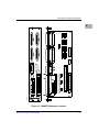
MVME712M Transition Module
The features of the MVME712M include:
❏
Four 25-pin multiprotocol EIA-232-D serial ports
(through P2 adapter)
❏
One independent printer port (through P2 adapter)
❏
Small Computer Systems Interface (SCSI) shielded connector bus
interface (through P2 adapter) for connection to internal and
external devices
❏
Green LED on module to indicate terminator power
❏
Yellow LED on module to indicate transceiver power
❏
SCSI terminating resistors mounted in sockets for end of cable or
middle of cable configuration
❏
Modem connection on module
❏
Radio Frequency Interference (RFI) protection on front panel
❏
Electrostatic Discharge (ESD) protection on front panel
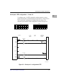
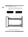
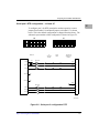
P2 Adapter Board
The MVME712M requires the use of the P2 adapter board. The features of
the P2 adapter board include:
1-2
❏
A connector that permits SCSI cable connection to other SCSI
devices and/or to MVME712M through a flat ribbon cable
❏
SCSI terminating resistors mounted in sockets, for end of cable or
middle of cable configuration
❏
Terminator power developed on the P2 adapter from the
+5 Vdc on connector P2, and fused (1 A) on the P2 adapter
❏
A connector that interfaces the EIA-232-D ports, printer port, SCSI,
and Ethernet signals to the MVME712M
Computer Group Literature Center Web Site