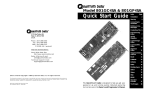
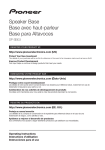
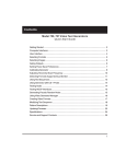
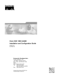
1
880 Series Generator
Quick Start Guide
agstr
Contents
®
Introduction
Video Interfaces
Computer Interfaces
Front Panel Interface
Status Indicators
Menu Selection Keys
Selecting menu items
Item selection examples
Using the Settings and
Options keys
2
2
3
4
4
5
5
5
6
Generator Operational Modes
Booting up the generator
Basic mode
Browse mode
8
8
8
9
Video Display Testing Procedures
Making physical connections
Selecting the device type and
interface
Selecting video formats
Selecting images
Web Interface
Establishing a Network
Environment
Working with the Virtual
Front Panel
Copying files from a PC to a
generator
Copying files from a
generator to a PC
This Quick Start Guide is designed to help get you up and running
quickly with your generator..
Model 880 Series Quick Start Guide
1
12
12
12
14
15
19
19
23
26
27
Introduction
This Quick Start Guide describes the basic features, functions and operating procedures for the 881 and 882 Quantum Data video test instruments for testing analog and
digital video display devices. The 881 provides features for testing video displays in
production environments. The 882 is its complement. It provides extended features to
test video displays for development environments and quality assurance applications.
Video Interfaces
This section describes the generator’s video interfaces. The video interfaces are shown
below and the table describes each connector (881 and 882 shown).
Interface
Description
1
SDI/HD-SDI connector outputs a serial digital signal per SMPTE 259M and
SMPTE 292M standards.
2
CVBS connector outputs an analog composite video baseband signal in
accordancewith SMPTE 170M standard.
3
S-VIDEO connector outputs an S-Video split luminance (Y) and chrominance
(C) analog video signal.
4
SPECIAL connector provides multiple outputs, including:
- digital composite sync
- line sync
- frame sync
- movable scope trigger (probe) pulse
- pixel clock signal
5
VGA OUT connector outputs analog component video or analog RGB signal.
6, 7
HDMI OUT (1/2) connectors output full single link HDMI video, as well as DVI
and modern HDMI-compatible digital video signals.
8, 9
HDMI IN (1/2) connectors for input of full single link HDMI video, as well as DVI
and modern HDMI-compatible digital video signals.
10
SPDIF-AV connector inputs audio from an external source.
Model 880 Series Quick Start Guide
2
Computer Interfaces
Computer Interfaces
This section describes the generator’s video interfaces. The video interfaces are shown
below and the table describes each connector.
Interface
Description
1
SERIAL connector provides RS-232C serial data communication interface for
the generator.
2
DEBUG connectoris for Quantum Data use only.
3
ETHERNET connector is used to connect the generator with a TCP/IP network,
for remote administration and control, and for sharing resources from a file
server.
4
GPIB connector provides IEEE-488 GPIB interface to the generator (882 only;
not provided on the 881 generator.
Model 880 Series Quick Start Guide
3
Front Panel Interface
Front Panel Interface
This section describes the front panel interface for operating the generator. The front
panel keys are shown below.
Status Indicators
Status indicators provide feedback about the operational status of the generator. The
graphic below shows the location of the status indicators.
Model 880 Series Quick Start Guide
4
Selecting Menu Items
Menu Selection Keys
You can access the generator’s menus using the menu selection keys depicted below.
Selecting menu items
When you press a menu selection key, a menu appears on the generator’s display.
Each menu item corresponds to a key located adjacent to the item. These keys are
called "soft keys because their functions change depending on the items that appear on
the generator's display. For example, for the menu shown below, the soft key at the
upper left corresponds to the System item on the generator's display.
Item selection examples
The following examples show the different types of menu items.
Model 880 Series Quick Start Guide
5
Settings and Options Keys
Using the Settings and Options keys
The Options key enables you to view or set basic options for the selected item. For
items with multiple pages of options, press the Options key again to view additional
pages. Typically, options are attributes that are either enabled or disabled. For example,
the screen below shows the options for a format. On this screen, the asterisk (*) next to
DSS means that DSS is selected, the + next to SyncOnG means that this option is
enabled, and the - signs next to Pedestal, SyncOnR, and SyncOnB mean that these
options are disabled. If you press the soft key adjacent to SyncOnR, the - will change to
a +, indicating the option is now enabled.
The Settings key enables you to view or set a parameter to a value. For example, the
screen below shows the settings for the video signal of a format. To change the value of
the XVSI, AVSI, or DVSI setting, press the soft keys next to the arrows on the bottom row
of the generator’s display until the blinking cursor is on the value you want to change.
Increment the value up or down by pressing the + and - keys.
Model 880 Series Quick Start Guide
6
Generator File System
The generator has a file system that can be stored on multiple media (storage devices
or locations). The 880 series generator file system is comprised of two main directories
(folders): 1) System and 2) Library. The System folder contains the realtime operating
system and firmware file (vxWorks) and the gateware. The Library folder contains the
following resource files:
File Type
Description
Fonts
Object files used to define the font types.
Formats
XML files for configuring the source list of formats.
FormatLib
XML files for configuring the source list of formats.
Images
C++ object files, executables, bitmaps and XML files for rendering images.
Sequences
XML files with instructions for test sequences.
Users
XML files for user configuration profiles.
Web
HTML files for the internal web server.
Model 880 Series Quick Start Guide
7
Generator Operational Modes
The generator has two operational modes: 1) Basic mode and 2) Browse mode. The
generator boots up in the Basic mode which is the main operating mode you will be
using. Both modes are described below along with instructions for booting up the
generator.
Booting up the generator
When the generator is powered up it presents a screen enabling you to select the boot
device. Selecting a boot device means that you can specify which medium (storage
location) the generator loads its operating system and firmware from. If you do not
press a key within five seconds the currently specified boot location is used and boot up
proceeds. This feature enables you to control where the generator boots from in instances where the default location is either inaccessible or known to have a suspect
application file. Follow the procedure below to boot the generator:
To boot the generator:
1.
Apply power to the generator. The following display appears.
If you are sure you want to boot from the current storage location you can let the
system boot automatically.
2.
To boot from an alternative device, press any key within five seconds. The following
display appears. The following screen appears on the generator’s display:
3.
Choose the !BootDev item by pressing the adjacent soft key.
Basic mode
The Basic mode is the main operating mode of the generator. Typically, you will use the
Basic mode when testing displays and sources. In Basic mode you can select formats
and images, create and run test sequences, view and edit object properties, and so on.
Model 880 Series Quick Start Guide
8
Browse Mode
In the Basic mode you make selections in the front panel with the item selection keys
and the soft keys.
Browse mode
Browse mode is for advanced users who want to load objects from different media and
program the generator function keys. When in Browse mode, the selection keys shown
below are active.
The procedure below describes how to place the generator in Browse mode:
To place the generator in Browse mode:
1.
Press and hold the Tools key. The message Hold to enter Browse Mode appears on
the generator’s display. Continue holding the Tools key until the Browser status
indicator lights. The following menu appears:
In Browse mode, you can view and use objects (resource files such as formats,
images and sequences) located in the generator’s flash memory, a network file
server, the generator’s PC card, or the generator’s cache memory.
Medium
Description
Flashmem
Non-volatile memory in generator.
NetPlace
File server connected with generator.
PCCard
Compact Flash card in generator.
Cache
Volatile memory in generator. This source contains objects that have
been used (loaded into cache) since the generator was started.
Model 880 Series Quick Start Guide
9
Operational Modes
2.
Choose the media type that you wish to browse through.
A list of folders on that medium appears on the generator’s display as shown below.
2.
Choose the folder you want to open by pressing the adjacent soft key. The contents
of the folder appears on the generator’s display.
3.
Continue selecting folders to open until you locate the item you need. To use an
item, press the adjacent soft key.
Setting the generator’s path
You can configure the generator to access resource files from any media storage
location. When you are in Basic mode the generator's Source list, Content list of
Sequence list display items in the folder that the format, image or sequence path
parameters are pointing to. However, the path parameter for formats, images and
sequences can be changed either through the command line or through the front panel
using the Browse mode which is shown below.
Changing the path parameter enables you to configure the generator to access format,
image, and sequence files stored on the media location that you specify. For example
you can set the format path to the PC card so that when you press the Source key in
Basic mode you get a list of formats in the PC card's Format folder. You may wish to set
the image path to the PC server so that when you press the Content key in the Basic
mode you access a list of images from the server's Image folder. You can set the
format, image or sequence path to any of the media storage locations (i.e. flash
memory, PC card, or on a file server).
Note: You can also set the generator's path using the command line interface. For
instructions refer to the User's Guide.
To set the generator’s path using the front panel:
1.
Place the generator in Browse mode by holding down the Tools key until the media
menu appears on the generator’s display as shown below.
2.
Choose the desired medium by pressing the adjacent soft key. The folders on the
selected medium (for example flash memory) appear on the generator’s display as
shown below.
Model 880 Series Quick Start Guide
10
Operational Modes
3.
Press the soft key adjacent to the Library folder. The contents of the selected folder
appears on the generator’s display as shown in the example below.
4.
Press the soft key adjacent to the folder you want to use. For example, to set the
format path, press the soft key adjacent to the Formats folder. The contents of the
Formats folder appears on the generator’s display.
5.
Select a format by pressing the adjacent soft key.
The format path is now set to the selected folder on the selected medium. In this
example, when you go back in to Basic mode and you press the Source key you will
get a list of formats in the Flashmem's Format folder.
Programming the generator’s function keys
The generator is equipped with four function keys (F1 through F4) that can be programmed as short-cuts to folders. The procedure below describes how to program the
function keys.
To program a function key as a folder short cut:
1.
Browse to the folder to which you want to create a short cut.
2.
Hold down a function key (F1, F2, F3, or F4) to assign the key to the folder.
Switching from Browse mode to Basic mode
You can switch back to the Basic mode when you are finished browsing for files.
To switch from Browse mode to Basic mode:
1.
Press and hold the Tools key. The message Hold to enter Basic Mode appears on
the generator’s display. Continue holding the Tools key until the Browser status
indicator turns off and the Tools menu appears.
Model 880 Series Quick Start Guide
11
Video Display Testing Procedures
This section provides an overview of the video testing process, which involves connecting the generator to the display under test, selecting the interface and format appropriate for the display, and then selecting images to exercise the display to ensure proper
functioning.
Making physical connections
Use the following table as a guide for connecting the generator to the display under
test. First identify the Signal type and determine the Port (Interface). Then select the
cable.
Display type
Information
Technology (IT)
Consumer
Equipment (CE)
Professional AV
Signal type
Port (Interface)
Cable
Computer - VESA
(DMT,CVT)
Analog Component VGA OUT
RGB
VGA to VGA
Computer - VESA
(DDWG)
Digital Component
RGB
HDMI OUT
HDMI to DVI
SDTV - ITU-470-6
baseband
Analog Composite
C VBS
C VBS
BNC to RCA 75
Ohms
SDTV - ITU-470-6
baseband
Analog Composite
S-VIDEO
S-VIDEO
S-Video (miniDin)
SDTV -CEA-861B
Analog Component VGA OUT
YPbPr
VGA to RCA
(optional - avail
from QDI
HDTV -CEA-861B
Digital Component
DVI RGB
HDMI OUT
HDMI to DVI
HDTV -CEA-861B
Digital component
HDMI RGB and
YCbCr
HDMI OUT
HDMI to HDMI
SDI (SMPTE-259M)
and HD-SDI
(SMPTE-292M-C)
Digital component
YCbCr
SDI/HD-SDI
BNC Coax
Selecting the device type and interface
After making the physical connections, you are ready to select the device type and
interface. If you are testing video displays, you will select Display as the device type
using the front panel keys.
You can select the interface using either the front panel keys or the command line
interface. The interface you specify will depend on the video display type you are testing.
It will be one of the following:
Model 880 Series Quick Start Guide
12
Video Display Testing Procedures
Interface
Description
VGA
For testing analog VESA displays and component consumer electronic
displays.
C VBS
For testing composite analog consumer electronic displays.
S-Video
For testing composite (separate luma and chroma) analog consumer
electronic displays.
HDMI-D
For testing DVI displays through the HDMI interface.
HDMI-H
For testing HDMI consumer electronic displays.
SDI/HD-SDI
For testing SDI and HD-SDI professional AV displays.
Once you have selected the display and the interface you can change the parameters
specifying the physical size of the display if your application calls for that. You can also
gate off the interface output temporarily if necessary. Use the procedures below.
To define the display size:
1.
After selecting the interface, press the Settings key. The following information
appears on the generator’s display.
2.
Navigate to the other parameters for physical size (VSIZ and USIZ) to set the display
size for your test application.
To gate off the interface:
1.
After selecting the interface, press the Options key. The following information
appears on the generator’s display.
2.
Enable or disable the interface output by pressing the adjacent soft key.
Selecting video formats
When you have selected the interface you next need to specify the format. A format
defines a set of video, timing, and sync parameters for a specific device or standard.
This section explains how to configure the generator to output video formats that are
supported by the device being tested.
Model 880 Series Quick Start Guide
13
Selecting Video Formats
Note: For more information about formats, see the 881/882 User's Guide.
Selecting formats automatically
When testing EDID-compatible displays, the generator can automatically update the
Source list to include only formats supported by the display under test.
To update the Source list automatically:
1.
Connect the generator to the display you want to test.
2.
Press the Sink key.
3.
Press the Options key. The following information appears on the generator’s display.
4.
Choose the Read EDID item by pressing the adjacent soft key. A + appears next to
Read EDID, indicating it is enabled.
The generator loads the Source list with formats supported by the connected display
(hot-plug formats read via EDID structure of attached display).
Note: To disable hot plug formats press the soft key adjacent to Read EDID. A next to Read EDID indicates it is disabled.
To bypass hot plug formats:
1.
Connect the generator to the display you want to test.
2.
Press the Sink key.
3.
Press the Options key. The following information appears on the generator’s display.
4.
Choose the HP Bypass item by pressing the adjacent soft key. A + appears next to
Read EDID, indicating it is enabled.
4.
Disable hot plug (enable hot plug bypass) by pressing the adjacent soft key until a '' (minus sign) is displayed indicating disabled.
Model 880 Series Quick Start Guide
14
Selecting Images
Selecting formats manually
When testing a display that is not EDID-compliant, you must manually choose formats
that are supported by the display. Note that once you select an interface the source list
of formats will be filtered to only those that are suitable for a particular video interface.
For example if you select CVBS as the interface the source list of formats will not
include the VESA formats.
The generator has a library of standard formats. For a description of how the library is
organized, see the 881/882 User's Guide.
Once you have selected a format you can modify the format options and settings if
necessary. For instructions on this refer to the User's Guide.
To select a format:
1.
Identify the type of display (composite television, component standard definition
television, component high definition television, computer equipment, or other
specialty display).
Check the specifications of your display for supported formats.
2.
Press the Source key to access the list of formats. A list of formats appear on the
generator’s display as shown below. To see all of the formats, press the + and keys.
The list of formats that appears when you press the Source key may be a filtered or
abbreviated list. Formats not suitable for the selected interface type will not appear
by default on the Source list.
The list of formats that appear when you press the Source key will be the formats in
the Format folder of the media storage location that you have set the format path
parameter to using either the Browse mode or command line (FMTP parameter).
4.
Choose a format by pressing the adjacent soft key.
Selecting images
Once you have determined the format or formats appropriate for testing the display, you
will apply a series of images suitable for evaluating the display. Of primary importance
is determining what type of display you are testing (for example, CRT or digital flat panel
display). You must also determine if you are testing composite TV and use images
appropriate for these formats and video types.
Each image in the generator’s library is intended to test one or more attributes of a
particular display type and video type.
Model 880 Series Quick Start Guide
15
Displaying Images
Displaying images
Use the following procedures to view primary images. Once you have selected an image
you can modify the image options if necessary.
To select an image:
1.
Identify the type of display (CRT or FPD) and the images that are used for testing
this type of display (see the table below).
2.
Press the Content key. A list of images appears on the generator’s display as
shown below. Press the + and - keys to see all of the images.
The list of images that appear when you press the Content key will be the images in
the Image folder of the media storage location that you have set the image path
parameter to using the Browse mode or the command line (IMGP parameter).
3.
Choose an image by pressing the adjacent soft key.
The table below provides a summary of analog CRT display characteristics and the
images used to evaluate them. For details on the images and display attributes, see
Appendix B, “Image Reference” of the User's Guide.
Display type Display
characteristic
Image
Analog CRT
Geometry (pin and
barrel, linearity)
Static images: Hatch (TVHatch, Hatch16,20) CirclesL, Geom_1 Geom-5, SMPTE133.
Focus
Focus and Text images.
Photometry
Flat, Ramp, ColorBar, SMPTEBar, TVBar.
(chrominance, levels)
Luminance
SMPTE133 Grays(5,9,11,16,32,64).
Gamma correction
SMPTE133 (checkerbox).
Resolution
BurstTCE, Burst(TV formats only), Grill(11,15,22,33,44).
Pulse (CE SDTV)
PulseBar.
Centering
Outline(0,1,2,3).
Voltage Regulation
Regulate.
Electromagnetic
Interference
EMITest(1,2,3,4,5).
Model 880 Series Quick Start Guide
16
Displaying Image Versions
The table below provides a summary of digital FPD display characteristics and the
images used to evaluate them. For details on the images and display attributes, see
Appendix B, “Image Reference” of the User's Guide.
Display type Display
characterisitic
Images
Digital Flat
Panel (fixed
pixel displays)
Flat, Raster, Ramp, Focus Text.
Pixel anomolies
(stuck pixels, miss
sampling)
Photometry
Flat, Flatgray, Ramp, ColorBar, SMPTEBar, SMPTE133.
(chrominance, levels)
Luminance
SMPTE133(grayscales), Grays(5,9,11,16,32,64).
Resolution
BurstTCE, Grill(11,15,22,33,44).
Centering
Outline(0,1,2,3).
Persistence
Animated images: Persist, Cubes, SlideX.
Displaying image versions
Many images have secondary or alternate versions and some images have many
versions. Use the procedures below to view the alternate and multiple image versions.
To view alternate image versions in the Content list:
1.
Select an image by pressing the Contents key.
2.
Enable and view image versions as follows:
Press the Options key. The following menu will appear on the generator’s display
for images with a single secondary image:
3.
Choose the Alternate item by pressing the adjacent soft key until a + appears next
to the item.
4.
Toggle back and forth between the images using the adjacent soft key.
Model 880 Series Quick Start Guide
17
Displaying Image Versions
To view multiple image versions in the Content list:
1.
Select an image by pressing the Contents key.
2.
Enable and view image versions as follows:
Press the Options key. The following menu appears on the generator’s display:
3.
Choose the More item by pressing the adjacent soft key until a + and Rendition
appears next to the item.
4.
Press the + and - keys to advance through the image versions. Each version shows
the format parameters for a different format in the Source list.
Model 880 Series Quick Start Guide
18
Web Interface
The generator has a built-in Web server that enables you to interact with the generator
using a PC and an Ethernet connection. The Web interface includes the following
functions:
• Virtual Front Panel for operating the generator remotely.
• Generator FTP Browser for copying files between media within the generator,
between generators, and between a generator and a PC.
• Format Editor for creating formats and modifying and viewing format parameters.
For more information about the Format Editor, Refer to the User's Guide for
instructions on using the Format Editor.
• CMD Terminal for operating the generator using the command line interface.
• Calibration reports (Currently not available)
This section describes how to operate the Virtual Front Panel and the Generator FTP
Browser.
Establishing a Network Environment
To utilize the Web interface features you have to create a network environment for your
generators. You must physically connect the generators to the network, and then configure their IP addresses and the IP address of the file server (which must be different).
Procedures for these tasks are described in this section.
In a typical networked environment, you will connect the generators to the corporate, IPbased Ethernet LAN. In this scenario, you connect a standard Ethernet patch cable
between the Ethernet port on the generator and a LAN access jack or to a local hub. The
file server is also connected to the LAN in the same manner.
Model 880 Series Quick Start Guide
19
Establishing a Network Environment
Another type of network scenario is to directly connect a single generator to a file server.
For a direct connection, you must use a crossover Ethernet cable and connect it from
the Ethernet port on the file server to the generator Ethernet port as shown below.
Note: If you are using a PC that is connected to a network that automatically assigns an
IP address, and you will be disconnecting from that network to connect to the crossover
cable and generator, you must manually enter an IP address into the PC so it can
communicate with the generator. The network portions of the IP addresses of the generator and the PC must match; the host portions must be different.
When the network connection on the generator is active, the Network LED lights on the
front panel.
Setting the generator's IP address
Each generator on the network must have a unique IP address if you want to control the
generator over a network, or want the generator to share resources located on a file
server. Typically, your site’s LAN administrator will provide you with IP addresses for
each generator. Depending on how your site’s LAN is configured, your LAN adminstrator
may also provide you with a subnet mask.
To set the IP address of the generator:
1.
Press the Tools key. The Tools menu appears on the generator’s display as shown
below.
2.
Choose the System item by pressing the adjacent soft key. The System menu
appears on the generator’s display as shown below.
3.
Choose the Network item by pressing the adjacent soft key. The generator’s IP
address and subnet mask appear on the generator’s display as shown below.
Model 880 Series Quick Start Guide
20
Setting the Generator's IP Address
4.
Press the Settings key. The Network Connection screen appears on the generator’s
display as shown below.
Note: If the IP Address configuration option is not visible, press the soft key adjacent to the arrow symbol by SubnetMask until IP Address appears.
5.
Change the IP address as follows:
a. Position the blinking cursor on the address digit you want to change. To do this,
press the soft key adjacent to the arrow by the address to move the cursor left or
right until it appears on the digit you want to change.
b. Adjust the value of the digit up or down by pressing the + or - keys. Repeat for
each IP address digit you want to change.
6. If necessary, change the subnet mask as follows:
a. If the SubnetMask configuration option is not visible, press the soft key adjacent
to the arrow symbol by IP Address until SubnetMask appears.
b. Position the blinking cursor on the subnet mask digit you want to change. To do
this, press the soft key adjacent to the arrow by the subnet mask to move the cursor
left or right until it appears on the digit you want to change.
c. Adjust the value of the digit up or down by pressing the + or - keys. Repeat for
each subnet mask digit you want to change.
7.
To save the changes, press the Enter (Options) key. The following choices appear
on the generator’s display:
To save the changes, choose the Yes item by pressing the adjacent soft key.
To exit without saving the changes, choose the No item.
Model 880 Series Quick Start Guide
21
Setting the Server's IP Address
To return to the Network Connection screen without saving the changes, choose the
Back item.
8.
Reboot the generator to enable the IP address change.
Setting the server's IP address in the generator
You must enter the IP address of the file server in each generator so the generator can
communicate with the file server. In addition, you can also enter a name (called the
Server Name) for the file server.
To specify the IP address and host name of the file server:
1.
Press the Tools key. The Tools menu appears on the generator’s display as shown
below.
2.
Choose the System item by pressing the adjacent soft key. The System menu
appears on the generator’s display as shown below.
3.
Choose the Server item by pressing the adjacent soft key. The host name and IP
address appear on the generator’s display.
4.
Press the Settings key. The Network Server (Server IP address) screen appears on
the generator’s display as shown below.
If the Server Address (IP address) configuration option is not visible, press the soft
key adjacent to the arrow symbol by Server Name until Server Address (IP address)
appears.
5.
Change the Server address as follows:
Model 880 Series Quick Start Guide
22
Virtual Front Panel
a. Position the blinking cursor on the address digit you want to change. To do this,
press the soft key adjacent to the arrow by the address to move the cursor left or
right until it appears on the digit you want to change.
b. Adjust the value of the digit up or down by pressing the + or - keys. Repeat for
each address digit you want to change.
6.
(Optional) Change the Server name as follows:
a. If the Server Name configuration option is not visible, press the soft key adjacent
to the arrow symbol by Server IP Address until Server Name appears.
b. Position the blinking cursor on the character you want to change. To do this,
press the soft key adjacent to the arrow by the name to move the cursor left or right
until it appears on the character you want to change.
c. Select the desired character by pressing the + or - keys to scroll through uppercase letters, lowercase letters, and numbers. Repeat for each character you want to
change.
7.
To save the changes, press the Enter (Options) key. The following choices appear
on the generator’s display:
To save the changes, choose the Yes item by pressing the adjacent soft key.
To exit without saving the changes, choose the No item.
To return to the Network Server screen without saving the changes, choose the
Back item.
Working with the Virtual Front Panel
The Virtual Front Panel enables you to perform remotely the same tasks as you would
with the generator’s front panel. To use the Virtual Front Panel, you must have a PC
connected to a generator either through an Ethernet LAN or locally through an Ethernet
crossover cable connected between the Ethernet ports on the generator and the PC.
These configurations are described in more detail in the User's Guide. You must also
have the Java Runtime Environment (JRE) 1.4.2 or later installed on your PC. You can
download the JRE from http://java.sun.com/j2se/1.4.2/download.html.
To use the Virtual Front Panel, you must know the IP address of the generator and
configure it with an IP address that is compatible with the IP address of your PC.
Model 880 Series Quick Start Guide
23
Virtual Front Panel
The following procedures describe how to access the Virtual Front Panel using a Web
browser.
To determine the IP address of the generator:
1.
Press the Tools key. The Tools menu appears on the generator’s display as shown.
2.
Choose the System item by pressing the adjacent soft key. The System menu
appears on the generator’s display as shown below.
To use the Virtual Front Panel:
1.
Open a Web browser (such as Internet Explorer) and type the generator’s IP address in the address entry field.
The generator home page appears in the browser.
Model 880 Series Quick Start Guide
24
Virtual Front Panel
You can add the page to your list of favorite pages in your Web browser to avoid
retyping the IP address each time you want to access the page.
2.
Click the Virtual Front Panel link. The Virtual Front Panel appears.
Model 880 Series Quick Start Guide
25
FTP Browser
If you create objects on a PC, such as images or formats, you can use the Generator
FTP Browser to copy these objects to a generator. You can also use the Generator FTP
Browser to copy objects between media in a generator and to copy objects from one
generator to another.
Copying files from a PC to a generator
You can copy files from the PC to the generator when you are upgrading the generators
with new system or library files.
To copy files from a PC to a generator:
1.
Access the generator’s Virtual Front Panel.
2.
From the Options menu (upper left corner of the Virtual Front Panel), choose the
FTP Browser menu item. The Generator FTP Browser appears. The Instrument Files
area shows the files stored on the generator. The Host Files area shows the files
stored on the PC.
2.
In the Host Files area, locate and select the file or folder you want to copy.
3.
In the Instrument Files area, locate the destination folder for the file as follows:
Model 880 Series Quick Start Guide
26
Copying Files with the Generator FTP Browser
In the Look in box, click the down arrow and select the storage medium where you
want to copy the file. Select tffs0 for the generator’s flash memory or card0 for the
generator’s PC card.
In the list of files, open the destination folder.
4.
In the Host Files area, click Download. The Transfer Files dialog box appears.
Verify that the source file or folder and the destination folder are correct, and then
click OK.
The Copying Files dialog box appears showing the status of the operation. When the
status is 100%, click Done.
Copying files from a generator to a PC
You can copy files from a generator back to your PC. This is useful if you need to save
custom formats or images saved only in a generator's local memory.
To copy files from a generator to a PC:
1.
Access the generator’s Virtual Front Panel.
2.
From the Options menu (upper left corner of the Virtual Front Panel), choose the
FTP Browser menu item. The Generator FTP Browser appears. The Instrument Files
area shows the files stored on the generator. The Host Files area shows the files
stored on the PC.
Model 880 Series Quick Start Guide
27
Copying Files with the Generator FTP Browser
3.
In the Instrument Files area, locate and select the file or folder you want to copy as
follows.
4.
In the Look in box, click the down arrow and select the medium where the file is
located. Select tffs0 for the generator’s flash memory or card0 for the generator’s
PC card.
5.
In the list of files, select the file or folder you want to copy.
6.
In the Host Files area, open the destination folder where you want to copy the files.
7.
In the Instrument Files area, click Upload. The Transfer Files dialog box appears.
Verify that the source file or folder and the destination folder are correct, and then
click OK.
The Copying Files dialog box appears showing the status of the operation. When the
status is 100%, click Done.
Model 880 Series Quick Start Guide
28
This manual for use with the following Models of Quantum Data Video Generators:
881 and 882
The following hardware options are covered:
-
GPIB Communications Port
Ethernet Communications Port
Serial Communications Port
NTSC/PAL TV Outputs (CVBS and S-Video)
VGA Analog Video Outputs
Single Link HDMI/DVI Digital Video Outputs
SDI/HD-SDI Output (Serial Digital Interface/High Definition) (optional interface)
Information based on the following generator firmware versions:
881/882:
Version 2.0.0
Entire contents
Copyright ©2005
by Quantum Data, Inc.
All rights reserved.
The information contained in
this document is provided for
use by our customers and may
not be incorporated into other
products or publications without the expressed written consent of Quantum Data.
Information furnished by Quantum Data is believed to be
accurate and reliable. However,
no responsibility is assumed
by Quantum Data for its use.
Quantum Data reserves the
right to make changes at any
time and without notice to its
products to improve performance, reliability, manufacturing
methods, and (or) marketability.
"Model 802 Series Quick Start Guide"
Part # 68-00203 Rev. A3
(25-July-2005)
Quantum Data, Inc.
2111 Big Timber Rd.
Elgin, IL 60123-1100
U.S.A.
®
Internet Connections
Phone: (847) 888-0450
Fax: (847) 888-2802
World Wide Web Site:
http://www.quantumdata.com
Sales E-mail:
[email protected]
Toll Free Support in the
USA
Phone: 1-888-252-6133
Customer Service E-mail:
[email protected]
Technical Support E-mail:
[email protected]
Model 880 Series Quick Start Guide
29