1
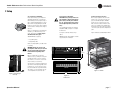
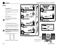
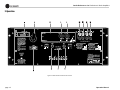
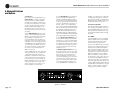
Studio Reference I & II Professional Studio Amplifiers
3 Operation
3.2 Front Panel Controls
and Indicators
A. Level Controls
Each channel’s output level can be adjusted
accurately using the 31-position detented level
controls on the front panel (see Section 4.4.1).
B. ODEP Indicators
During normal operation of the amplifier, the
ODEP (Output Device Emulation Protection)
indicators glow brightly to show the presence
of reserve thermodynamic energy. They dim
proportionally as energy reserves decrease. In
the rare event that energy reserves are depleted,
the indicators turn off and ODEP proportionally
limits the output drive so the amplifier can
safely continue operating even under severe
conditions. These indicators also help to identify more unusual operating conditions (see
Figure 4.1).
C. IOC Indicators
The IOC (Input Output Comparator) indicators
serve as sensitive distortion indicators to provide proof of distortion-free performance.
Operation Manual
Under normal conditions, the indicators remain
off. They flash if the output waveform differs
from the input by 0.05% or more (see
Section 4.2). If the input signal level is too
high, the indicators will also flash brightly with
a half-second hold delay to show input overload or output clipping. Note: The channel 2
IOC indicator stays on in Parallel-Mono mode.
See Section 4.1.
D. Signal Presence Indicators
These indicators flash synchronously with the
amplifier’s audio output to show signal presence. Note: These indicators may not flash at
very low input signal levels. See Section 4.1.
E. Enable Indicator
This indicator lights when the amplifier has
been “enabled” or turned on, and AC power is
available.
F. Enable Switch
This push button is used to turn the amplifier
on and off. When turned on, the output is
muted for about four seconds to protect your
system from start-up transients. This is why a
power sequencer is rarely needed for multiple
units. (The turn-on delay can be changed. Contact Crown’s Technical Support Group for
details.)
G. Dust Filter
The dust filter removes large particles from the
air drawn in by the cooling fan. In most cases,
the fan will not run so the filter will remain
clean. If the filter becomes dirty, it can be
removed for easy cleaning (see Section 4.3).
H. Dynamic Range/Level Meters
A five-segment output meter is provided for
each channel. The meters are factory-set to
show dynamic range of the signals in dB, which
is computed as the ratio of peak to average output power. Also, the meter can optionally be set
to show output levels (see Section 4.1).
• Meter Switches
Two switches behind the front panel can be
used to customize the output meters (H). By
default, the meters display dynamic range. To
make the meters display signal levels or to turn
them off, see Section 4.4.2.
page 15