1
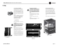
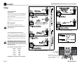
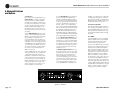
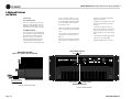
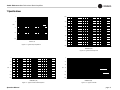
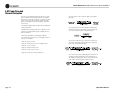
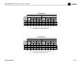
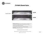
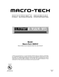
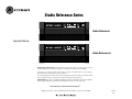
Studio Reference I & II Professional Studio Amplifiers
2 Setup
2.6 Wire Your System
2.6.1 Stereo Mode
Typical input and output wiring is shown in
Figure 2.8.
CHANNEL 2
LOUDSPEAKER
Turn off the amplifier and set the
Stereo/Mono Switch to Stereo.
CHANNEL 1
INPUTS: Connect input wiring for both channels.
CHANNEL 2
NOTE: Crown provides a reference of wiring pin
assignments for commonly used connector
types in the Crown Amplifier Application Guide
available at www.crownaudio.com.
–
+
CHANNEL 1
LOUDSPEAKER
+
–
MIXER
CH-2
CH-1
FX
PUSH
OUTPUTS: Each output channel has two sets of
binding posts to make it easier to connect multiple loudspeaker cables to each channel.
PUSH
Maintain proper polarity (+/–) on output connectors.
Connect Channel 1 loudspeaker’s positive (+)
lead to Channel 1 positive (red) terminal of amp;
repeat for negative (–). Repeat Channel 2 wiring
as for Channel 1.
Reference
S T U D I O
STUDIO REFERENCE
AMPLIFIER
STEREO
PARALLEL
MONO
BRIDGE
MONO
CAUTION: TURN OFF AMPLIFIER
CAUTION: In Stereo mode, never tie an
amplifier’s outputs together directly, and
never parallel them with the output of
another amplifier. Such connections do not
result in increased output power, but may
activate the protection circuitry to prevent overheating.
Operation Manual
BEFORE CHANGING THIS SWITCH!
Figure 2.8
Stereo Wiring
page 9