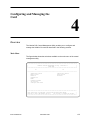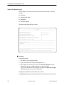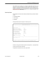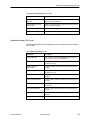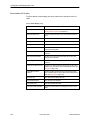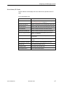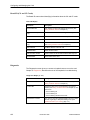
1
AREA CODE CHANGE
Please note that the area code for
Paradyne Corporation in Largo, Florida
has changed from 813 to 727.
For any Paradyne telephone number that
appears in this manual with an 813 area
code, dial 727 instead.
HOTWIRE 5100 DSL
ACCESS SYSTEM
CENTRAL OFFICE
USER’S GUIDE
Document No. 5100-A2-GB20-00
November 1996
Copyright 1996 Paradyne Corporation.
All rights reserved.
Printed in U.S.A.
Notice
This publication is protected by federal copyright law. No part of this publication may be copied or distributed,
transmitted, transcribed, stored in a retrieval system, or translated into any human or computer language in any form
or by any means, electronic, mechanical, magnetic, manual or otherwise, or disclosed to third parties without the
express written permission of Paradyne Corporation, 8545 126th Avenue North, P.O. Box 2826, Largo,
FL 33779-2826.
Paradyne Corporation makes no representation or warranties with respect to the contents hereof and specifically
disclaims any implied warranties of merchantability or fitness for a particular purpose. Further, Paradyne Corporation
reserves the right to revise this publication and to make changes from time to time in the contents hereof without
obligation of Paradyne Corporation to notify any person of such revision or changes.
Changes and enhancements to the product and to the information herein will be documented and issued as a new
release to this manual.
Warranty, Sales, and Service Information
Contact your sales or service representative directly for any help needed. For additional information concerning
warranty, sales, service, repair, installation, documentation, or training, use one of the following methods:
Via the Internet: Visit the Paradyne World Wide Web site at http://www.paradyne.com
Via Telephone: Call our automated call system to receive current information via fax or to speak with a
company representative.
— Within the U.S.A., call 1-800-870-2221
— International, call 813-530-2340
Trademarks
All products and services mentioned herein are the trademarks, service marks, registered trademarks or registered
service marks of their respective owners.
Printed on recycled paper
A
November 1996
5100-A2-GB20-00
Important Regulatory Information
Important Safety Instructions
1. Read and follow all warning notices and instructions marked on the product or included in the manual.
2. This product is intended to be used in a UL-Listed/CSA-Certified computer with a 3-wire grounding type plug (a
plug which has a grounding pin). This is a safety feature. Equipment grounding is vital to ensure safe operation.
Do not defeat the purpose of the grounding type plug by modifying the plug or using an adapter.
3. When installed in the final configuration, the product must comply with the applicable Safety Standards and
regulatory requirements of the country in which it is installed. If necessary, consult with the appropriate regulatory
agencies and inspection authorities to ensure compliance.
In addition, if the equipment is to be used with telecommunications circuits, take the following precautions:
— Never install telephone wiring during a lightning storm.
— Never install telephone jacks in wet locations unless the jack is specifically designed for wet locations.
— Never touch uninsulated telephone wires or terminals unless the telephone line has been disconnected at the
network interface.
— Use caution when installing or modifying telephone lines.
— Avoid using a telephone (other than a cordless type) during an electrical storm. There may be a remote risk of
electric shock from lightning.
— Do not use the telephone to report a gas leak in the vicinity of the leak.
5100-A2-GB20-00
November 1996
B
Contents
About This Guide
Purpose and Audience . . . . . . . . . . . . . . . . . . . . . . . . . . . . . . . . . . . . . . . . . . . v
Document Summary . . . . . . . . . . . . . . . . . . . . . . . . . . . . . . . . . . . . . . . . . . . . . v
Product-Related Documents . . . . . . . . . . . . . . . . . . . . . . . . . . . . . . . . . . . . . . vi
1
About HotWire DSL
What Is the HotWire 5100 DSL Access System? . . . . . . . . . . . . . . . . . . . . 1-1
Features . . . . . . . . . . . . . . . . . . . . . . . . . . . . . . . . . . . . . . . . . . . . . . . . . . . . . . . 1-1
Operating Environment . . . . . . . . . . . . . . . . . . . . . . . . . . . . . . . . . . . . . . . . . . 1-2
HotWire DSL Requirements . . . . . . . . . . . . . . . . . . . . . . . . . . . . . . . . . . . . . . 1-3
Hardware Requirements . . . . . . . . . . . . . . . . . . . . . . . . . . . . . . . . . . . . . 1-3
Software Requirements . . . . . . . . . . . . . . . . . . . . . . . . . . . . . . . . . . . . . . 1-3
Distance Requirements . . . . . . . . . . . . . . . . . . . . . . . . . . . . . . . . . . . . . . 1-3
2
Installing and Connecting the Card
Package Contents . . . . . . . . . . . . . . . . . . . . . . . . . . . . . . . . . . . . . . . . . . . . . . 2-1
Installation Steps . . . . . . . . . . . . . . . . . . . . . . . . . . . . . . . . . . . . . . . . . . . . . . . . 2-1
Setting I/O Base Address . . . . . . . . . . . . . . . . . . . . . . . . . . . . . . . . . . . . . . . . 2-2
Setting IRQ Switches to Off . . . . . . . . . . . . . . . . . . . . . . . . . . . . . . . . . . . . . . 2-4
Installing the CO Cards in the PC . . . . . . . . . . . . . . . . . . . . . . . . . . . . . . . . . 2-4
Connecting the Card to the LAN Network and POTS Network . . . . . . . . . 2-5
Connecting to the LAN Network . . . . . . . . . . . . . . . . . . . . . . . . . . . . . . . 2-6
Connecting to the POTS Network . . . . . . . . . . . . . . . . . . . . . . . . . . . . . . 2-6
Connecting to the POTS Network Using Rack-Mounted POTS
Splitters . . . . . . . . . . . . . . . . . . . . . . . . . . . . . . . . . . . . . . . . . . . . . . . . . . . . 2-6
Connecting to the POTS Network Using Standalone POTS
Splitters . . . . . . . . . . . . . . . . . . . . . . . . . . . . . . . . . . . . . . . . . . . . . . . . . . . . 2-10
Connecting to a Terminal . . . . . . . . . . . . . . . . . . . . . . . . . . . . . . . . . . . . . . . . . 2-10
Installing the Software . . . . . . . . . . . . . . . . . . . . . . . . . . . . . . . . . . . . . . . . . . . 2-11
Installing the Kernel Device Driver and Central Management
Utility Software . . . . . . . . . . . . . . . . . . . . . . . . . . . . . . . . . . . . . . . . . . . . . . 2-11
Installing the SNMP Agent Software . . . . . . . . . . . . . . . . . . . . . . . . . . . 2-12
5100-A2-GB20-00
November 1996
i
Contents
3
Accessing the Central Management Utility
Overview . . . . . . . . . . . . . . . . . . . . . . . . . . . . . . . . . . . . . . . . . . . . . . . . . . . . . . 3-1
Accessing the Central Management Utility Locally . . . . . . . . . . . . . . . . . . . 3-2
Accessing the Central Management Utility Using a VT100-Compatible
Terminal . . . . . . . . . . . . . . . . . . . . . . . . . . . . . . . . . . . . . . . . . . . . . . . . . . . . . . . 3-2
Accessing the Central Management Utility Using Telnet . . . . . . . . . . . . . . 3-3
Setting the Terminal Interface Options . . . . . . . . . . . . . . . . . . . . . . . . . . . . . 3-4
Automatically Running the Central Management Utility . . . . . . . . . . . . . . . 3-5
4
Configuring and Managing the Card
Overview . . . . . . . . . . . . . . . . . . . . . . . . . . . . . . . . . . . . . . . . . . . . . . . . . . . . . . 4-1
Main Menu . . . . . . . . . . . . . . . . . . . . . . . . . . . . . . . . . . . . . . . . . . . . . . . . . 4-1
Menus That Require Input . . . . . . . . . . . . . . . . . . . . . . . . . . . . . . . . . . . . 4-2
Read-Only Menus . . . . . . . . . . . . . . . . . . . . . . . . . . . . . . . . . . . . . . . . . . . 4-3
Configuring and Managing the Card . . . . . . . . . . . . . . . . . . . . . . . . . . . . . . . 4-4
Operational Status (CO Cards) . . . . . . . . . . . . . . . . . . . . . . . . . . . . . . . . 4-4
Operational Status (CP Cards) . . . . . . . . . . . . . . . . . . . . . . . . . . . . . . . . 4-5
Error Status (CO Cards) . . . . . . . . . . . . . . . . . . . . . . . . . . . . . . . . . . . . . . 4-6
Error Status (CP Cards) . . . . . . . . . . . . . . . . . . . . . . . . . . . . . . . . . . . . . . 4-7
Board ID (CO and CP Cards) . . . . . . . . . . . . . . . . . . . . . . . . . . . . . . . . . 4-8
Diagnostics . . . . . . . . . . . . . . . . . . . . . . . . . . . . . . . . . . . . . . . . . . . . . . . . . 4-8
Reset . . . . . . . . . . . . . . . . . . . . . . . . . . . . . . . . . . . . . . . . . . . . . . . . . . . . . . 4-9
Firmware Upgrade . . . . . . . . . . . . . . . . . . . . . . . . . . . . . . . . . . . . . . . . . . . 4-10
Set Filters . . . . . . . . . . . . . . . . . . . . . . . . . . . . . . . . . . . . . . . . . . . . . . . . . . 4-10
Configure DSL Cards . . . . . . . . . . . . . . . . . . . . . . . . . . . . . . . . . . . . . . . . 4-12
5
Configuring the SNMP Agent
SNMP Interface Model . . . . . . . . . . . . . . . . . . . . . . . . . . . . . . . . . . . . . . . . . . . 5-1
Configuration . . . . . . . . . . . . . . . . . . . . . . . . . . . . . . . . . . . . . . . . . . . . . . . . . . . 5-2
Configuring System Variables and Community Strings . . . . . . . . . . . . 5-2
Configuring System Trap Destination . . . . . . . . . . . . . . . . . . . . . . . . . . . 5-2
PDU Trace . . . . . . . . . . . . . . . . . . . . . . . . . . . . . . . . . . . . . . . . . . . . . . . . . . . . . 5-3
ii
November 1996
5100-A2-GB20-00
Contents
6
Diagnostics
Overview . . . . . . . . . . . . . . . . . . . . . . . . . . . . . . . . . . . . . . . . . . . . . . . . . . . . . . 6-1
LED Status . . . . . . . . . . . . . . . . . . . . . . . . . . . . . . . . . . . . . . . . . . . . . . . . . . . . . 6-2
Using the Loopback Tests . . . . . . . . . . . . . . . . . . . . . . . . . . . . . . . . . . . . . . . . 6-4
LAN Loopback . . . . . . . . . . . . . . . . . . . . . . . . . . . . . . . . . . . . . . . . . . . . . . 6-5
Local Loopback . . . . . . . . . . . . . . . . . . . . . . . . . . . . . . . . . . . . . . . . . . . . . 6-5
Remote Loopback . . . . . . . . . . . . . . . . . . . . . . . . . . . . . . . . . . . . . . . . . . . 6-6
A
Pinouts
J1 Ethernet Connector Pinouts . . . . . . . . . . . . . . . . . . . . . . . . . . . . . . . . . . . . A-1
J2 DSL Network Access Connector Pinouts . . . . . . . . . . . . . . . . . . . . . . . . A-1
B
Installing POTS Splitter at Customer Premises
How to Install the POTS Splitter . . . . . . . . . . . . . . . . . . . . . . . . . . . . . . . . . . . B-1
C
Technical Specifications
Technical Specifications . . . . . . . . . . . . . . . . . . . . . . . . . . . . . . . . . . . . . . . . . . C-1
Glossary
Index
5100-A2-GB20-00
November 1996
iii
About This Guide
Purpose and Audience
This guide describes how to install and configure the Central Office (CO)
component of the HotWire 5100 DSL Access System. The guide is written for
administrators and technicians who maintain the networks that support HotWire
DSL operation.
To install and configure the Customer Premises (CP) portion of the HotWire DSL,
refer to the HotWire 5100 DSL Access System Customer Premises User’s Guide.
Document Summary
5100-A2-GB20-00
Section
Description
Chapter 1
About HotWire DSL. Provides an overview of the
operation of the HotWire DSL and lists its hardware
and software requirements.
Chapter 2
Installing and Connecting the Card. Describes how to
install the HotWire DSL hardware and software.
Chapter 3
Accessing the Central Management Utility. Describes
how to access the HotWire DSL Central Management
Utility to configure and manage the CO PC card.
Chapter 4
Configuring and Managing the Card. Describes how to
configure and manage the CO PC card.
Chapter 5
Configuring the SNMP Agent. Describes how to
configure the SNMP Agent.
Chapter 6
Diagnostics. Describes the meaning of the LEDs on the
CO PC card and how to use the HotWire DSL loopback
tests.
Appendix A
Pinouts. Provides pinouts for the CO PC card.
November 1996
v
Contents
Section
Description
Appendix B
Installing POTS Splitter at Customer Premises.
Describes how to install the POTS splitter at the
customer premises.
Appendix C
Technical Specifications. Lists the technical
specifications of the CO PC card.
Glossary
Defines acronyms and terms used in this document.
Index
Lists key terms, acronyms, concepts, and sections in
alphabetical order.
Product-Related Documents
Document Number
Document Title
5100-A2-GB21
HotWire 5100 DSL Access System Customer
Premises User’s Guide
Contact your sales representative to order additional product documentation.
vi
November 1996
5100-A2-GB20-00
About HotWire DSL
1
What Is the HotWire 5100 DSL Access System?
The HotWire DSL Access System provides high-speed Internet or corporate LAN
access over traditional twisted-pair telephone wiring. Using HotWire DSL modem
cards, PC users at remote locations can connect to a Central Office (CO) to
access Internet service providers or corporate networks.
Features
HotWire DSL has the following features:
High-speed data rates.
— 1544 or 2048 kbs downstream (toward customer premises) and 64 kbs
upstream (toward CO site) Asymmetric Digital Subscriber Loop (ADSL)
— 2560, 2240, 1920, 1600, 1280, 960, or 640 kbs downstream and 1088,
952, 816, 680, 544, 408, or 272 kbs upstream Rate-adaptive Digital
Subscriber Loop (RADSL)
5100-A2-GB20-00
Remote access from the Customer Premises (CP) to the CO from up to a
distance of 15,000 ft with standard #26 AWG wiring.
Security features in the HotWire DSL CO hardware that prevent remote users
from accessing another user’s PC files or LAN traffic.
Prevention against degradation of voice telephone service while using ADSL
or RADSL service.
Primary network management support via SNMP. SNMP management of all
the HotWire DSL cards is accomplished over a single connection to the CO
PC from a network management system (such as HP OpenView). The CO
PC gathers all management information for each of the CO cards and
responds to the SNMP requests on behalf of the cards.
November 1996
1-1
About HotWire DSL
These specific management information bases (MIBs) are supported:
— MIB II System and Interface Groups
— Enterprise Specific Device MIB
Operating Environment
The following figure shows the HotWire DSL operating environment.
Central Office
Customer Premises
CO PC
Telephone
Handset
Ethernet
CP PC
CO
Card
Up to
18
CO
Cards
POTS
Splitter
POTS/
DSL
POTS/
DSL
POTS
Splitter
CP
Card
CO Switch
496-14983
Installation of the CP hardware and software is described in the HotWire 5100
DSL Access System Customer Premises User’s Guide.
1-2
November 1996
5100-A2-GB20-00
About HotWire DSL
HotWire DSL Requirements
Hardware Requirements
HotWire DSL requires an Intel 80486 or Pentium, NEBS-compliant PC with:
Up to 18 card slots that can accommodate full-size (12-inch) ISA HotWire
DSL interface cards
3.5″ diskette drive (1.44 Mbs)
250 watt power supply (minimum)
325 kb free disk space
Software Requirements
The product requires Microsoft Windows NT 3.51, workstation or server version.
Using telnet to access the HotWire DSL Central Management Utility requires that
the CO PC be running a telnet server, such as that sold by Pragma System, and
a telnet client, such as that sold by NetManage.
Distance Requirements
The HotWire DSL enables operation at distances up to 15,000 ft with standard
#26 AWG (.40 mm) telephone wiring.
5100-A2-GB20-00
November 1996
1-3
Installing and Connecting the
Card
2
Package Contents
The HotWire DSL CO product consists of:
H
CO DSL card
H
HotWire DSL CO Product Disks
H
HotWire DSL POTS Splitter
H
User’s guide
Installation Steps
" Procedure
To install the HotWire DSL CO product, follow these steps:
1. Set the I/O base address of the card by setting dual in-line package (DIP)
switches on the card (page 2-2).
2. Set all hardware interrupt request (IRQ) switches to off (page 2-4).
3. Install the card into the PC (page 2-4).
4. Cable the card to the local LAN network (hub) (page 2-6).
5. Cable the card to the POTS splitter (page 2-6).
6. Cable the POTS splitter to the subscriber loop and CO switch (page 2-6).
7. Install the HotWire DSL CO product software (page 2-11).
8. Configure (if necessary) the DSL mode and MAC and IP filter addresses
using the HotWire DSL Central Management Utility as described in
Chapter 4, Configuring and Managing the Card.
9. Configure the SNMP Agent as described in Chapter 5, Configuring the SNMP
Agent.
5100-A2-GB20-00
November 1996
2-1
Installing and Connecting the Card
In addition to Steps 1–9, a HotWire DSL CP card must be installed in a
customer’s PC (as described in the HotWire 5100 DSL Access System Customer
Premises User’s Guide) and a DSL line must be provisioned by the POTS
provider to make a DSL link operational.
If you are also responsible for installing the POTS splitter at the customer
premises, refer to Appendix B, Installing POTS Splitter at Customer Premises.
Setting I/O Base Address
The DIP switch bank SW1 shown in the following figure is used to assign the
card’s I/O base address.
12
34
5
12
6
7
12
ON
1
2
3
4
5 6
7
34
8
34
5
6
7
8
8
496-14980
To help you keep track of your configuration, use the following configuration table
to record the CO PC slot in which you have installed a CO card. The cards can
occupy any available slot.
The channel numbers (0–17) are tied to I/O base addresses as shown in the
configuration table. Use these numbers to identify a card when using the HotWire
DSL Central Management Utility.
NOTE:
Ensure that the I/O base addresses used by the CO cards do not conflict with
the I/O base addresses of any other cards in the CO PC.
2-2
November 1996
5100-A2-GB20-00
Installing and Connecting the Card
Configuration Table for SW1 Switches
I/O Base
Address
Switch Settings
1 2
3 4
0
0x210
On Off
Off Off Off On Off Off
1
0x220
On Off
Off Off On Off Off Off
2
0x240
On Off
Off On Off Off Off Off
3
0x250
On Off
Off On Off On Off Off
4
0x260
On Off
Off On On Off Off Off
5
0x280
On Off
On Off Off Off Off Off
6
0x290
On Off
On Off Off On Off Off
7
0x2A0
On Off
On Off On Off Off Off
8
0x2B0
On Off
On Off On On Off Off
9
0x2C0
On Off
On On Off Off Off Off
10
0x2D0
On Off
On On Off On Off Off
11
0x320
On On
Off Off On Off Off Off
12
0x330
On On
Off Off On On Off Off
13
0x340
On On
Off On Off Off Off Off
14
0x350
On On
Off On Off On Off Off
15
0x360
On On
Off On On Off Off Off
16
0x380
On On
On Off Off Off Off Off
17
0x390
On On
On Off Off On Off Off
CO PC Slot Channel
Number
Number
5100-A2-GB20-00
November 1996
5
6
7
8
2-3
Installing and Connecting the Card
Setting IRQ Switches to Off
IRQ (hardware interrupt request) DIP switch banks SW2 and SW3 select an IRQ.
IRQs are not used by the CO cards. Set these switches to Off for proper
operation of the card.
SW2
ON
1
2
3
4
5 6
7
12
8
34
5
12
6
7
12
SW3
ON
1
2
3
34
8
34
5
6
7
8
4
496-15017
Installing the CO Cards in the PC
Procedure
1. Access the card slots of the PC.
2. Insert a CO card into a vacant 16-bit ISA expansion slot.
3. Observe the SYS LED after the card is inserted. It should blink while a
self-test is in progress and then remain on. If it does not, the card is defective
and should be replaced. (See LED Status in Chapter 6 for a description of the
card’s LEDs.)
2-4
November 1996
5100-A2-GB20-00
Installing and Connecting the Card
Connecting the Card to the LAN Network and POTS
Network
The figure below identifies the connectors that enable you to connect the card to
your LAN and POTS networks.
J1 for LAN connection
J2 for POTS connection
12
34
5
12
6
7
34
8
12
34
5
6
7
8
J2
6-Pin
Modular Jack
(Network Access
Connector)
J1
8-Pin
Modular Jack
(Ethernet
Connector)
496-14981
5100-A2-GB20-00
November 1996
2-5
Installing and Connecting the Card
Connecting to the LAN Network
Procedure
1. Plug the end of an 8-pin modular cable into the J1 Ethernet connector of the
CO card.
2. Plug the other end of the cable into your LAN hub connector.
Connecting to the POTS Network
The HotWire DSL product comes with one of two types of POTS splitters:
rack-mounted or standalone. The installation procedures for these two types of
splitters follow.
Connecting to the POTS Network Using Rack-Mounted POTS Splitters
Procedure
1. Install the POTS splitter rack and its multi-pin blocks at a distance from the
CO PC and POTS lines so that it is convenient to run connecting leads.
2. Insert POTS splitter cards into rack.
3. Connect rack connector P2 to multi-pin block #1; connect rack connector P3
to multi-pin block #2. (P2 connects POTS splitters 1 through 12 to block #1.
P3 connects POTS splitters 13 through 24 to block #2. There are two splitters
per card.)
2-6
November 1996
5100-A2-GB20-00
Installing and Connecting the Card
Multi-pin
Block #1
Connects to
Multi-pin
Block #2
P2
P3
POTS Splitter Rack
496-15026
5100-A2-GB20-00
November 1996
2-7
Installing and Connecting the Card
Four rows of pins of a multi-pin block are dedicated to each CO card/POTS
splitter pair. For example, Pins A1–4, B1–4, C1–4, and D1–4 are associated
with POTS splitter #1 in the rack and the CO card connected to connector #1
of the multi-pin block. Pins A5–8, B5–8, C5–8, and D5–8 are associated with
POTS splitter #2 in the rack and the CO card connected to connector #2 of
the multi-pin block, and so on.
Mounting
Ear
C
D
To
Subscriber
Loop
B
A
Tip
(D1)
To
CO
Card
Ring
(D2)
Tip
(A3)
Ring
(A4)
To
CO
Switch
Connectors
#1 – #4
Connectors
#9 – #12
Connectors
#5 – #8
Mounting
Ear
2-8
November 1996
496-15025
5100-A2-GB20-00
Installing and Connecting the Card
Always connect the CO switch tip and ring leads to the bottom two
A-column pins of a four-row set: A3(tip)–A4(ring), A7(tip)–A8(ring),
A11(tip)–A12(ring), and so on.
Always connect the subscriber loop tip and ring leads to the top two
D-column pairs: D1(tip)–D2(ring), D5(tip)–D6(ring), D9(tip)–D10(ring),
and so on.
4. Plug the end of an 8-pin modular cable into the J2 network access connector
of a CO card.
5. Plug the other end of the cable into the appropriate DSL connector of the
multi-pin block (Connector #1 in the figure on page 2-8).
6. Connect the tip lead of the CO switch pair to the appropriate pin of the
multi-pin block (A3 in the figure on page 2-8).
7. Connect the ring lead of the CO switch line to the appropriate pin of the
multi-pin block (A4 in the figure on page 2-8).
8. Connect the tip lead of the subscriber loop to the appropriate pin of the
multi-pin block (D1 in the figure on page 2-8).
9. Connect the ring lead of the subscriber loop to the appropriate pin of the
multi-pin block (D2 in the figure on page 2-8).
10. Jumper pins B to pins C using bridge clips (B1–C1, B2–C2, B3–C3, B4–C4 in
the figure below).
If you are using POTS monitoring bridge clips, place them on B3–C3 or
B4–C4.
B and C
(with Bridge Clip)
A
D
1
2
3
4
496-15023
5100-A2-GB20-00
November 1996
2-9
Installing and Connecting the Card
Connecting to the POTS Network Using Standalone POTS Splitters
Procedure
1. Install the splitter at a distance from the CO PC and POTS lines so that it is
convenient to run connecting leads.
2. Plug the end of an 8-pin modular cable into the J2 network access connector
of the CO card.
3. Connect the tip lead of the cable to the POTS splitter connector labeled T1 as
shown in the figure. (There is a POTS splitter associated with each card.)
LAN
Network
Ethernet
CO Card
POTS Splitter
J1
T1 T2
J2
T3 T4
Tip
DSL Ring
Tip
Tip
Subscriber Loop
Ring
Ring
CO Switch
496-14984
4. Connect the ring lead of the cable to the POTS splitter connector labeled T2.
5. Connect the tip lead of the subscriber loop to the splitter connector
labeled T1.
6. Connect the ring lead of the subscriber loop to the splitter connector
labeled T2.
7. Connect the tip lead of the CO switch to the splitter connector labeled T3.
8. Connect the ring lead of the CO switch to the splitter connector labeled T4.
Connecting to a Terminal
Procedure
1. If you plan to use a VT100-compatible terminal for management of the CO
card (as described in Chapter 4) or a PC running a terminal emulator, plug
the end of a serial cable into the COM port of the CO PC.
2. Plug the other end of the cable into your terminal’s serial port.
2-10
November 1996
5100-A2-GB20-00
Installing and Connecting the Card
Installing the Software
The HotWire DSL CO product software consists of three components as shown in
following table.
Software Component
Function
Kernel Device Driver
Contains the privilege level to communicate with the CO
card. It routes the read/write requests from/to the CO card
as needed by applications.
Central Management Utility
Enables you to configure and manage the CO card.
SNMP Agent
Enables you to manage CO cards remotely using the
Simple Network Management Protocol (SNMP).
Installing the Kernel Device Driver and Central Management Utility
Software
Use the following procedure to install the kernel device driver and central
management utility software.
Procedure
1. If you previously installed a version of the HotWire DSL software, go to
Step 2. If not, go to Step 6.
2. Start the Registry Editor from the Program Manager by executing the file
REGEDT32.EXE.
If necessary, use the Browse option on the Run pop-up menu to find the file.
3. Determine the path to the Windows NT System 32 Drivers (normally
c:\Windows\System32\drivers or
c:\WinNT35\System32\drivers).
4. Select HKEY_LOCAL_MACHINE on the Local Machine window. Select the
Subkey SYSTEM→CurrentControlSet→Control→VirtualDeviceDriver.
Edit the parameter VDD (by double-clicking on the right-hand window) to
remove the entry c:\windows\system32\drivers\boravdd.dll (or
c:\WinNT35\System32\drivers\boravdd.dll).
5. Close the Registry Editor.
6. Open an MS-DOS window and insert the floppy labeled CO PC HotWire
Windows NT Kernel Driver into drive A.
7. Stop the kernel driver by issuing the command net stop genport at the
prompt.
8. Copy the a:\Genport.sys driver into the Windows NT System 32 Drivers
directory, i.e., copy a:\genport.sys
5100-A2-GB20-00
November 1996
2-11
Installing and Connecting the Card
c:\Windows\system32\drivers\genport.sys (or
c:\WinNT35\System32\drivers\genport.sys).
9. Type a:\regini a:\genport.ini.
10. Reboot the CO PC.
11. Insert the floppy labeled CO PC Windows NT Central Management Utility
Software into an available floppy drive (drive A is assumed in Step 13).
12. Select File→Run from the Program Manager menu.
13. Type a:setup.exe and click the OK button.
Installing the SNMP Agent Software
Before installing the SNMP agent on the CO PC, be sure the following
prerequisites are met:
H
Windows NT 3.51 workstation or server operating system.
H
A LAN NIC (Network Interface Card) installed in the CO PC with proper driver
for the card.
H
A TCP/IP protocol stack (included with NT) installed and configured, bound to
the NIC.
H
The kernel driver provided with the product must be installed (page 2-11).
H
If the SNMP agent provided with Windows NT is installed, it must be
deactivated. To check for its installation, look under the Main group, under the
Services Icon. If it is installed, stop it and change the startup to manual so it
will not start automatically.
Use the following procedure to install the SNMP agent software.
1. Insert the floppy labeled CO PC Windows NT SNMP Agent Software into an
available floppy drive (drive A is assumed in Step 13).
2. Select File→Run from the Program Manager menu.
3. Type a:setup.exe and click the OK button.
Since the SNMP agent is typically running in the background, the following
procedure is recommended to ensure good response time to SNMP requests:
" Procedure
1. Under the Main group, double click on Control Panel, and then on the System
icon.
2. On the System dialog box, click on the Tasking... button.
3. Select Foreground and Background Applications Equally Responsive.
Follow the steps described in Chapter 5 to configure the SNMP Agent.
2-12
November 1996
5100-A2-GB20-00
Accessing the Central
Management Utility
3
Overview
There are three ways to access the CO card in order to configure and manage it:
By using the PC monitor and keyboard to access the central management
utility, as described in Accessing the Central Management Utility Locally on
page 3-2.
By using a VT100-compatible terminal or PC running a terminal emulator
program to access the central management utility, as described in Accessing
the Central Management Utility Using a VT100-Compatible Terminal on
page 3-2.
By using a TCP/IP system to access the central management utility via telnet,
as described in Accessing the Central Management Utility Using Telnet on
page 3-3
Chapter 4, Configuring and Managing the Card, describes the operation of the
central management utility.
NOTE:
You cannot use the local and the terminal-based or telnet-based central
management utilities simultaneously.
5100-A2-GB20-00
November 1996
3-1
Accessing the Central Management Utility
Accessing the Central Management Utility Locally
The procedure that follows describes how to use a locally attached keyboard and
monitor to access the central management utility.
Procedure
1. Install the software from the product disk as described in Installing the
Software in Chapter 2.
2. Access a MS-DOS window.
3. At the MS-DOS prompt, type:
cd c:\HOTWIRE
hotwire.exe
4. Refer to Chapter 4 for instructions on configuring the CO card.
Accessing the Central Management Utility Using a
VT100-Compatible Terminal
The procedure that follows describes how to use a VT100-compatible terminal or
a PC running a terminal emulator program to access the central management
utility.
NOTE:
Using a VT100-compatible terminal or terminal emulator requires that you
first use a PC monitor and keyboard to run the c:\HOTWIRE\hotwire.exe
file or perform the procedure described in Automatically Running the Central
Management Utility on page 3-5 so that hotwire.exe runs automatically
at boot time. Because the terminal-based central management utility does not
report operating system errors, it is recommended that you have a keyboard
and monitor attached to the CO PC.
Do not exit the central management utility from the terminal. If you do, you
must restart the utility from the PC keyboard as described in Step 3 in the
following procedure or reboot the CO PC if you have configured the utility to
run automatically at boot time as described in Automatically Running the
Central Management Utility on page 3-5.
Procedure
1. Ensure that the terminal interface options of the central management utility
are appropriate for your environment. See Setting the Terminal Interface
Options on page 3-4.
2. Connect the VT100-compatible terminal or terminal emulator to the
appropriate COM port of the CO PC.
3-2
November 1996
5100-A2-GB20-00
Accessing the Central Management Utility
3. From the PC keyboard, type:
cd c:\HOTWIRE
hotwire.exe
Alternatively, follow the procedure described in Automatically Running the
Central Management Utility on page 3-5.
4. Read Chapter 4, Configuring and Managing the Card.
Accessing the Central Management Utility Using
Telnet
The procedure that follows describes how to use a TCP/IP system to access the
central management utility via telnet.
Procedure
1. To open a telnet session to the CO PC, type:
telnet <IP address of CO PC>
2. Type:
cd c:\HOTWIRE
hotwire.exe
3. Read Chapter 4, Configuring and Managing the Card.
NOTE:
When using telnet, press the Esc key twice whenever the central
management utility requires that you press the Esc key.
5100-A2-GB20-00
November 1996
3-3
Accessing the Central Management Utility
Setting the Terminal Interface Options
The terminal interface options of the terminal-based central management utility
are set in the c:\HOTWIRE\hotwire.ini file. If you want to change any of the
options, use the following procedure.
" Procedure
1. Make a backup copy of the hotwire.ini file in case the file becomes
corrupted during editing, i.e., copy hotwire.ini hotwire.bak.
2. Edit the file with any ASCII text editor using the information provided in the
following table.
Parameter
Description
Baud Rate
Sets the communications rate. Possible values:
H 9600
H 19200 (default)
Port Name
Sets the COM port. Possible values:
H COM1
H COM2
H NONE (default)
Selecting NONE disables the central management
utility when accessed from the serial port.
Flow Control
Sets the flow control protocol. Possible values:
H XON_XOFF (default)
H DTR_DSR
H RTS_CTS
H NONE
Select NONE (all uppercase) if your terminal does not
support any of the protocols listed.
If you choose DTR_DSR, make sure that your
terminal is connected and powered on to avoid
hanging the CO PC.
3-4
November 1996
5100-A2-GB20-00
Accessing the Central Management Utility
Automatically Running the Central Management
Utility
The following procedure describes how to configure Windows NT so that the
HotWire DSL Central Management Utility runs automatically at boot time. This
procedure enables a user to use the terminal-based central management utility
without having a monitor and keyboard attached to the CO PC.
Procedure
1. Double-click on the Windows NT Startup group icon.
2. From the Windows NT Program Manager select File→New.
3. Click the Program Item and then click OK. Enter the following information in
the Program Items Properties menu:
Description: CMU
Command Line: craft.bat
Working Directory: c:\HOTWIRE
4. Click OK. An icon is created in the Startup group window.
5. Start the Registry Editor from the Program Manager by executing the file
REGEDT32.EXE.
If necessary, use the Browse option on the Run pop-up menu to find the file.
6. Select HKEY_LOCAL_MACHINE on the Local Machine window. Select the
Subkey Software→Microsoft→Windows NT→Current Version→WinLogon
7. Select Edit→Add Value. Enter the following information:
Value Name: AutoAdminLogon
Data: REG_SZ
Click OK.
8. Enter 1 (one) in the String menu and save.
9. Select Edit→Add Value. Enter the following information:
Value Name: Default Password
Data: REG_SZ
Click OK.
10. Enter the password for the administrator of the system and save. Close all
menus.
11. Reboot the CO PC. While it is rebooting, press F2 (or Esc on some
machines) to run the CO PC startup utility.
12. Select the option that disables the CO PC from halting when an error
message is reported to the screen (e.g., Pause on Post Error or
Initialization Error Halts).
5100-A2-GB20-00
November 1996
3-5
Accessing the Central Management Utility
13. Power down the CO PC.
14. Disconnect the CO PC monitor and keyboard.
15. Power on the CO PC.
NOTE:
The file c:\HOTWIRE\craft.bat delays the start of the
c:\HOTWIRE\hotwire.exe file until after the Windows NT COM port driver
is started. If the default 15-second delay is too short, use an ASCII editor to
edit this file to increase the value.
3-6
November 1996
5100-A2-GB20-00
Configuring and Managing the
Card
4
Overview
The Hotwire DSL Central Management Utility enables you to configure and
manage the HotWire CO cards as described in the following sections.
Main Menu
The figure below shows the selections available on the main menu of the central
management utility.
ÎÎÎÎÎÎÎÎÎÎÎÎÎÎÎÎÎÎÎÎÎÎÎÎÎ
ÎÎÎÎÎÎÎÎÎÎÎÎÎÎÎÎÎÎÎÎÎÎÎÎÎ
ÎÎÎÎÎÎÎÎÎÎÎÎÎÎÎÎÎÎÎÎÎÎÎÎÎ
ÎÎÎÎÎÎÎÎÎÎÎÎÎÎÎÎÎÎÎÎÎÎÎÎÎ
ÎÎÎÎÎÎÎÎÎÎÎÎÎÎÎÎÎÎÎÎÎÎÎÎÎ
ÎÎÎÎÎÎÎÎÎÎÎÎÎÎÎÎÎÎÎÎÎÎÎÎÎ
ÎÎÎÎÎÎÎÎÎÎÎÎÎÎÎÎÎÎÎÎÎÎÎÎÎ
ÎÎÎÎÎÎÎÎÎÎÎÎÎÎÎÎÎÎÎÎÎÎÎÎÎ
ÎÎÎÎÎÎÎÎÎÎÎÎÎÎÎÎÎÎÎÎÎÎÎÎÎ
ÎÎÎÎÎÎÎÎÎÎÎÎÎÎÎÎÎÎÎÎÎÎÎÎÎ
ÎÎÎÎÎÎÎÎÎÎÎÎÎÎÎÎÎÎÎÎÎÎÎÎÎ
ÎÎÎÎÎÎÎÎÎÎÎÎÎÎÎÎÎÎÎÎÎÎÎÎÎ
ÎÎÎÎÎÎÎÎÎÎÎÎÎÎÎÎÎÎÎÎÎÎÎÎÎ
ÎÎÎÎÎÎÎÎÎÎÎÎÎÎÎÎÎÎÎÎÎÎÎÎÎ
ÎÎÎÎÎÎÎÎÎÎÎÎÎÎÎÎÎÎÎÎÎÎÎÎÎ
ÎÎÎÎÎÎÎÎÎÎÎÎÎÎÎÎÎÎÎÎÎÎÎÎÎ
******************************************************************************
*
HotWire Central Management Utility Version X.X
*
*
Main Menu
*
******************************************************************************
CO
CP
______________________________________________________________________________
Operational Status
Error Status
Board ID
Diagnostics
Reset
Firmware Upgrade
Set Filters
Configure DSL Cards
Operational Status
Error Status
Board ID
*****************************************************************************
*Use arrow keys to highlight a selection and then press Enter.
*
*Use Esc to exit the HotWire utility.
Use Ctrl-R to refresh the screen. *
*****************************************************************************
5100-A2-GB20-00
November 1996
4-1
Configuring and Managing the Card
Menus That Require Input
The following menus require that you input information (other than the channel
number):
H
Set Filters
H
Configure DSL Card
H
Diagnostics
H
Firmware Upgrade
The figure below shows the Filters menu.
ÎÎÎÎÎÎÎÎÎÎÎÎÎÎÎÎÎÎÎÎÎÎÎÎÎ
ÎÎÎÎÎÎÎÎÎÎÎÎÎÎÎÎÎÎÎÎÎÎÎÎÎ
ÎÎÎÎÎÎÎÎÎÎÎÎÎÎÎÎÎÎÎÎÎÎÎÎÎ
ÎÎÎÎÎÎÎÎÎÎÎÎÎÎÎÎÎÎÎÎÎÎÎÎÎ
ÎÎÎÎÎÎÎÎÎÎÎÎÎÎÎÎÎÎÎÎÎÎÎÎÎ
ÎÎÎÎÎÎÎÎÎÎÎÎÎÎÎÎÎÎÎÎÎÎÎÎÎ
ÎÎÎÎÎÎÎÎÎÎÎÎÎÎÎÎÎÎÎÎÎÎÎÎÎ
ÎÎÎÎÎÎÎÎÎÎÎÎÎÎÎÎÎÎÎÎÎÎÎÎÎ
ÎÎÎÎÎÎÎÎÎÎÎÎÎÎÎÎÎÎÎÎÎÎÎÎÎ
ÎÎÎÎÎÎÎÎÎÎÎÎÎÎÎÎÎÎÎÎÎÎÎÎÎ
ÎÎÎÎÎÎÎÎÎÎÎÎÎÎÎÎÎÎÎÎÎÎÎÎÎ
ÎÎÎÎÎÎÎÎÎÎÎÎÎÎÎÎÎÎÎÎÎÎÎÎÎ
ÎÎÎÎÎÎÎÎÎÎÎÎÎÎÎÎÎÎÎÎÎÎÎÎÎ
ÎÎÎÎÎÎÎÎÎÎÎÎÎÎÎÎÎÎÎÎÎÎÎÎÎ
ÎÎÎÎÎÎÎÎÎÎÎÎÎÎÎÎÎÎÎÎÎÎÎÎÎ
ÎÎÎÎÎÎÎÎÎÎÎÎÎÎÎÎÎÎÎÎÎÎÎÎÎ
******************************************************************************
*
Filters
*
******************************************************************************
Channel Number (0-17)
MAC Filter Source Address 1
IP Filter Source Address 1
MAC Filter State 1 (1=On, 0=off)
IP Filter State 1 (1=On, 0=off)
MAC Broadcast Filter State (1=On, 0=Off
Unknown Protocol Filter State (1=On, 0=Off)
Save the Changes ( Y(es) or N(o) )
:
:
:
:
:
:
:
:
6
00:00:00:00:00:00
110.112.113.114
0
0
0
0
N
******************************************************************************
*Channel Number (0-17)
>>
******************************************************************************
*Comments:
******************************************************************************
******************************************************************************
*Use Del to erase entry.
*
*Use Esc to return to the main menu. Use Ctrl-R to refresh the screen.
*
******************************************************************************
" Procedure
To input information:
1. Use Enter to move through the fields.
2. Type a parameter in the input field (designated by >> ).
3. After making your choices, type Y(es) in the Save the Changes field and
press Esc to save your changes and return to the main menu.
If you do not want to save your changes, type N(o) in the Save the Changes
field and press Esc to return to the main menu.
Pressing Ctrl-R updates the information on the screen.
A Comments field gives you status information about the operation of the screen.
4-2
November 1996
5100-A2-GB20-00
Configuring and Managing the Card
(The Set Filters menu enables you to configure multiple MAC and IP filter source
addresses, as well as individually set the filter states for these addresses to On
(enable) or Off (disable). Use the left and right arrow keys to scroll through these
addresses and state selections. See page 4-12 for a complete description of the
Configure DSL Cards menu items.)
Read-Only Menus
The following menu items return read-only information after you input a channel
number:
Operational Status
Error Status
Board ID
The figure below shows an example of a read-only menu.
ÎÎÎÎÎÎÎÎÎÎÎÎÎÎÎÎÎÎÎÎÎÎÎÎÎ
ÎÎÎÎÎÎÎÎÎÎÎÎÎÎÎÎÎÎÎÎÎÎÎÎÎ
ÎÎÎÎÎÎÎÎÎÎÎÎÎÎÎÎÎÎÎÎÎÎÎÎÎ
ÎÎÎÎÎÎÎÎÎÎÎÎÎÎÎÎÎÎÎÎÎÎÎÎÎ
ÎÎÎÎÎÎÎÎÎÎÎÎÎÎÎÎÎÎÎÎÎÎÎÎÎ
ÎÎÎÎÎÎÎÎÎÎÎÎÎÎÎÎÎÎÎÎÎÎÎÎÎ
ÎÎÎÎÎÎÎÎÎÎÎÎÎÎÎÎÎÎÎÎÎÎÎÎÎ
ÎÎÎÎÎÎÎÎÎÎÎÎÎÎÎÎÎÎÎÎÎÎÎÎÎ
ÎÎÎÎÎÎÎÎÎÎÎÎÎÎÎÎÎÎÎÎÎÎÎÎÎ
ÎÎÎÎÎÎÎÎÎÎÎÎÎÎÎÎÎÎÎÎÎÎÎÎÎ
ÎÎÎÎÎÎÎÎÎÎÎÎÎÎÎÎÎÎÎÎÎÎÎÎÎ
ÎÎÎÎÎÎÎÎÎÎÎÎÎÎÎÎÎÎÎÎÎÎÎÎÎ
ÎÎÎÎÎÎÎÎÎÎÎÎÎÎÎÎÎÎÎÎÎÎÎÎÎ
ÎÎÎÎÎÎÎÎÎÎÎÎÎÎÎÎÎÎÎÎÎÎÎÎÎ
ÎÎÎÎÎÎÎÎÎÎÎÎÎÎÎÎÎÎÎÎÎÎÎÎÎ
ÎÎÎÎÎÎÎÎÎÎÎÎÎÎÎÎÎÎÎÎÎÎÎÎÎ
ÎÎÎÎÎÎÎÎÎÎÎÎÎÎÎÎÎÎÎÎÎÎÎÎÎ
******************************************************************************
*
Operational Status (CO)
*
******************************************************************************
Channel number
6
Ethernet Pkts Received
76945
Ethernet Pkts Transmitted
7116
Ethernet Octets Received
423389358
Ethernet Octets Transmitted
555567
DSL Pkts Received
7115
DSL Pkts Transmitted
268140
DSL Octets Received
569727
DSL Octets Transmitted
206647187
MAC Broadcast Pkts Rcvd
0
MAC Broadcast Pkts Xmtd
0
Link
Up
Ethernet Link Integrity
Good
______________________________________________________________________________
Channel Number (0-17)
>>
******************************************************************************
* Use Esc to return to the main menu. Use Ctrl-R to refresh the screen.
*
******************************************************************************
To select a card, type the channel number in the input field (>>) and press Enter.
To return to the main menu, press Esc.
To update the information on the screen, press Ctrl-R.
5100-A2-GB20-00
November 1996
4-3
Configuring and Managing the Card
Configuring and Managing the Card
The central management utility enables you to:
Monitor the status of the CO card and the CP card with which it
communicates by using the Operating Status and Error Status menus
Identify the version numbers associated with the CO and CP cards by
selecting the Board ID menu
Run loopback tests on the cards by selecting the Diagnostics menu
Cause a firmware reboot of the card by selecting the Reset menu
Upgrade the card’s firmware by selecting the Firmware Upgrade menu
Set DSL mode by selecting the Configure DSL Cards menu
Set MAC and IP filter addresses by selecting the Set Filters menu
The sections that follow describe these selections.
Operational Status (CO Cards)
The Operational Status screen displays the amount of data sent and received by
the CO cards.
Operational Status Display (CO) (1 of 2)
4-4
Parameter
Description
Channel Number
User-supplied number that identifies the channel. (See
Setting I/O Base Address in Chapter 2.)
Ethernet Packets Received
Number of Ethernet packets received by the CO card from
the LAN segment.
Ethernet Packets
Transmitted
Number of Ethernet packets transmitted from the CO card
to the LAN segment.
Ethernet Octets Received
Number of Ethernet octets received by the CO card from
the LAN segment.
Ethernet Octets
Transmitted
Number of Ethernet octets transmitted from the CO card
to the LAN segment.
DSL Packets Received
Number of DSL packets received by the CO card from the
CP card.
DSL Packets Transmitted
Number of DSL packets transmitted from the CO card to
the CP card.
DSL Octets Received
Number of DSL octets received by the CO card from the
CP card.
DSL Octets Transmitted
Number of DSL octets transmitted from the CO card to the
CP card.
November 1996
5100-A2-GB20-00
Configuring and Managing the Card
Operational Status Display (CO) (2 of 2)
Parameter
Description
MAC Broadcast Packets
Received
Number of MAC Broadcast Packets received by the CO
card from the LAN segment.
MAC Broadcast Packets
Transmitted
Number of MAC Broadcast Packets transmitted to the CO
card from the LAN segment.
Link
State of the DSL link (up or down).
Ethernet Link Integrity
State of the Ethernet link (good or bad).
Operational Status (CP Cards)
The Operational Status screen displays the amount of data sent and received by
the CP cards.
Operational Status Display (CP)
5100-A2-GB20-00
Parameter
Description
Channel Number
User-supplied number that identifies the channel. (See
Setting I/O Base Address in Chapter 2.)
ISA Bus Packets Received
Number of packets received by the CP card from the ISA
bus of the CP card.
ISA Bus Packets
Transmitted
Number of packets sent to the ISA bus of the PC by the
CP card.
ISA Bus Octets Received
Number of octets received by the CP card from the ISA
bus of the CP card.
ISA Bus Octets Transmit
Number of the octets sent to the ISA bus of the PC by the
CP card.
DSL Packets Received
Number of DSL packets received by the CP card from the
CO card.
DSL Packets Transmitted
Number of DSL packets transmitted from the CP card to
the CO card.
DSL Octets Received
Number of DSL octets received by the CP card from the
CO card.
DSL Octets Transmitted
Number of DSL octets transmitted from the CP card to the
CO card.
Link
State of the DSL link (up or down).
November 1996
4-5
Configuring and Managing the Card
Error Status (CO Cards)
The Error Status screen displays the errors related to the operation of the CO
cards.
Error Status Display (CO)
4-6
Parameter
Description
Channel Number
User-supplied number that identifies the channel. (See
Setting I/O Base Address in Chapter 2.)
Ethernet CRC Errors
Number of Ethernet CRC errors encountered by the CO
card.
DSL CRC Errors
Number of DSL CRC errors encountered by the CO card.
Errored Minutes
Number of minutes in which an error has occurred.
Severely Errored Minutes
Number of minutes in which 10 errors have occurred.
Ethernet Discarded Packets
Number of Ethernet frames discarded by the CO card
because of invalid data.
Ethernet Dropped Packets
Number of Ethernet packets dropped because of a buffer
overflow.
DSL Discarded Packets
Number of the DSL frames discarded by the CO card
because of invalid data.
DSL Dropped Packets
Number of DSL packets dropped because of a buffer
overflow.
Invalid IP Packets Filtered
Number of IP packets filtered out because the IP source
address was not in the IP source address filter table (see
Set Filters, page 4-10).
Invalid MAC Packets
Filtered
Number of MAC packets filtered out because the MAC
source address was not in the MAC source address filter
table (see Set Filters, page 4-10).
Time Link Up
Time that the link initially came up.
Link Restarted Time
Time the link was restarted.
Link Reset TIme
Time the card was last reset.
Link Down State Transition
Number of times that the link changed from up to down
state.
November 1996
5100-A2-GB20-00
Configuring and Managing the Card
Error Status (CP Cards)
The Error Status screen displays the errors related to the operation of the CP
cards.
Error Status Display (CP)
5100-A2-GB20-00
Parameter
Description
Channel Number
User-supplied number that identifies the channel. (See
Setting I/O Base Address in Chapter 2.)
ISA FIFO CRC Errors
Number of FIFO CRC errors encountered by the CP card.
DSL CRC Errors
Number of DSL CRC errors encountered by the CP card.
Errored Minutes
Number of minutes in which an error has occurred.
Severely Errored Minutes
Number of minutes in which 10 errors have occurred.
ISA FIFO Dropped Packets
Number of FIFO packets discarded by the CP card
because of invalid data.
DSL Discarded Packets
Number of DSL frames discarded by the CO card because
of invalid data.
DSL Dropped Packets
Number of DSL packets dropped because of a buffer
overflow.
Link State Down Transition
Number of times the link changed from up to down.
Time Link Up
Time that the link initially came up.
Card Reset Time
Time that the card was last reset.
Link Restarted Time
Time the link was last restarted.
November 1996
4-7
Configuring and Managing the Card
Board ID (CO and CP Cards)
The Board ID screen shows identifying information about the CO and CP cards.
Board ID Display
Parameter
Description
Channel Number
User-supplied number that identifies the channel. (See
Setting I/O Base Address in Chapter 2.)
Software Version (CO card
only)
Version number of the central management utility.
Firmware Version
Version number of the firmware currently loaded.
Hardware Release
Release level of the card.
Base Address (CO card
only)
The I/O base address as set by DIP switches on the card.
(See Setting I/O Base Address in Chapter 2.)
MAC Address
The MAC address of the CO card.
Model Number
Model number of card.
DSL Firmware Version
Version number of the firmware related to DSL chip set.
Serial Number
Serial number of the card.
Diagnostics
The Diagnostics screen gives you access to loopback tests to run on the card.
Chapter 6, Diagnostics, discusses the use of the loopbacks in troubleshooting.
Diagnostics Display (1 of 2)
Parameter
Description
Channel Number
User-supplied number that identifies the channel. (See
Setting I/O Base Address in Chapter 2.)
Locate LED
Flashes the LED on the card selected by the channel
number (see Setting I/O Base Address in Chapter 2). The
choices are:
0=Turn flashing off
1=Turn flashing on
2=Turn flashing off after 30 seconds
Clear Status Counters
4-8
Type Y(es) to reset the operational status and error status
counters. Type N(o) to keep the existing count. (See
Operational Status ( CO Cards), page 4-4.)
November 1996
5100-A2-GB20-00
Configuring and Managing the Card
Diagnostics Display (2 of 2)
Parameter
Description
Loopback Type
Loopbacks available to test the operation of the CP card:
H 1=Local Loopback – enables data received from the
CO ISA bus to be looped back by the DSL firmware on
the CO card
H 2=Remote Loopback – enables data received from the
CO ISA bus to be looped back by the DSL firmware on
the CP card
H 3=LAN – enables data received from the CO card ISA
bus to be looped back by the Ethernet on-board
transceiver
For a detailed description of the loopbacks, refer to
Chapter 6, Diagnostics.
Loopback Enable
Type Y(es) and press Enter to begin the selected
loopback. Type N(o) and press Enter to end the loopback.
" Procedure
1. Choose a channel number.
2. Choose a loopback type.
3. Type Y(es) and press Enter to run the loopback.
The status of the loopback is displayed on the screen.
NOTE:
A remote loopback should not be run on a CO card with model number 5161
if the CP card with which it is communicating is running any application. (To
determine model number, see Board ID on page 4-8.)
Reset
The Reset screen enables you to perform a firmware reset of the card. The reset
function requires that you supply a channel number.
5100-A2-GB20-00
November 1996
4-9
Configuring and Managing the Card
Firmware Upgrade
The Firmware Installation screen enables you download code into the firmware of
the CO card.
Firmware Upgrade
Parameter
Description
Channel Number
User-supplied number that identifies the channel. (See
Setting I/O Base Address in Chapter 2.)
CO Firmware Version
Current firmware version.
Firmware Filename
Filename containing the code to be downloaded.
Start Firmware Download
Type Y(es) and press Enter to begin the download; Type
N(o) and press Enter to cancel the download.
Set Filters
The Filters screen enables you to select the filter operation of the CO card.
Filters Display (1 of 2)
Parameter
Description
Channel Number
User-supplied number that identifies the channel. (See
Setting I/O Base Address in Chapter 2.)
MAC Filter Source Address
Used to filter the data sent from the CO card to the
CP card. The CO card sends only those packets to its
attached CP card that have a source MAC address that
matches one of the addresses in its filter table.
Filtering MAC source addresses provides security benefits
by keeping users separate from one another on the LAN
segment.
You can configure up to 4 addresses. Use the left and
right arrow keys to scroll through these addresses.
4-10
November 1996
5100-A2-GB20-00
Configuring and Managing the Card
Filters Display (2 of 2)
Parameter
Description
IP Filter Source Address
Used to filter the data that is sent from the CP card to the
CO LAN segment. The CO card puts only those packets
on the LAN segment that match one of the addresses in
its filter table.
Filtering IP source addresses prevents a user from trying
to “spoof” a reply to the router by using someone else’s IP
address.
Use this option only if the service provider will be using
static IP address assignment. Because the filter address is
entered by the CO central management utility program, it
is fixed and will not work properly if the service provider
allocates IP addresses dynamically (i.e., each time a user
requests a session, a new IP address is allocated to that
user).
You can configure up to 8 addresses. Use the left and
right arrow keys to scroll through these addresses.
MAC Filter State
Type 1 (one) and press Enter to enable filtering; Type 0
(zero) and press Enter to disable filtering. The default is
disabled.
You can set the filter state for each MAC Filter Source
Address selected. Use the left and right arrow keys to
scroll through the states.
IP Filter State
Type 1 (one) and press Enter to enable filtering; Type 0
(zero) and press Enter to disable filtering. The default is
disabled.
You can set the filter state for each IP Filter Source
Address selected. Use the left and right arrow keys to
scroll through the states.
MAC Broadcast Filter State
Type 1 (one) and press Enter to enable filtering; Type 0
(zero) and press Enter to disable filtering. The default is
disabled.
Used to filter broadcast MAC packets that are not IP or
ARP in order to reduce data traffic to CP card.
Note: If you are using a router on the CP PC, you need to
disable this parameter.
Unknown Protocol Filter
State
Type 1 (one) and press Enter to enable filtering; Type 0
(zero) and press Enter to disable filtering. The default is
disabled.
Used to filter packets other than IP or ARP.
Note: Invalid packet counters counts invalid packets
regardless of the setting of this parameter (see
page 4-6).
Save the Changes
5100-A2-GB20-00
Type Y(es) and press Esc to save the changes and return
to the main menu. Type N(o) and press Esc to return to
the main menu without saving changes.
November 1996
4-11
Configuring and Managing the Card
Configure DSL Cards
The Configure DSL Card screens enables you to set the data rate of the CO
card.
Configure DSL Display
Parameter
Description
Channel Number
User-supplied number that identifies the channel. (See
Setting I/O Base Address in Chapter 2.)
Downstream Date Rate
Downstream data rates for ADSL cards:
H 1.5440 Mbs
H 2.0480 Mbs
Downstream data rates for RADSL cards:
H 2560 kbs
H 2240 kbs
H 1920 kbs
H 1600 kbs
H 1280 kbs
H 960 kbs
H 640 kbs
Upstream Date Rate
Upstream data rates for RADSL cards:
H 1080 kbs
H 952 kbs
H 816 kbs
H 680 kbs
H 544 kbs
H 408 kbs
H 272 kbs
Configure the Card
Type Y(es) and press Esc to save the changes and return
to the main menu. Type N(o) and press Esc to return to
the main menu without saving changes.
" Procedure
1. Choose a channel number from the initial screen that is displayed.
2. Choose a data rate from the second screen that is displayed
3. Type Y(es) or N(o) in the Configure the Card field and press Esc as
described above.
4-12
November 1996
5100-A2-GB20-00
Configuring the SNMP Agent
5
SNMP Interface Model
The DSL modem SNMP management model is that of a single CO PC addressed
by its IP Host name. The PC has multiple interfaces:
The PC’s NIC card
Three interfaces for each of the PC’s DSL modem cards
— The modem card
— The modem card’s Ethernet interface
— The modem card’s DSL interface
The interface numbers are as follows:
5100-A2-GB20-00
Interface Number
Description
1
PC NIC (LAN card)
1000
DSL modem 1
1001
DSL modem 1 Ethernet interface
1002
DSL modem 1 DSL interface
2000
DSL modem 2
2001
DSL modem 2 Ethernet interface
2002
DSL modem 2 DSL interface
November 1996
5-1
Configuring the SNMP Agent
Configuration
After installing the SNMP agent (as described in Chapter 2), you can configure
the following SNMP options:
H
System Name: a name for this CO PC.
H
System Contact: an administrator of this CO PC.
H
System Location: a room or rack location identifier for this CO PC.
H
Community Strings: The community string is used to identify and authenticate
information transactions between the SNMP manager and agent. Therefore,
you must configure the manager and agent to have the same community.
The default community is “public.” A different community may be used for
read-only transactions and for read/write transactions.
H
Trap destination
Close and restart the agent application after making changes to the configuration
so that the new values will be used.
Configuring System Variables and Community Strings
Use the following procedure to configure the system variables and community
string:
" Procedure
1. Start the HotWire DSL SNMP Agent utility by clicking on its icon.
2. Select Options→Configuration from the menu.
3. Fill in the parameter fields.
4. Click OK.
Configuring System Trap Destination
Traps are unsolicited messages about the state of the DSL card sent by the
SNMP agent to the SNMP manager. The agent will generate the following traps:
5-2
H
Warm start: Upon starting the agent.
H
Link up: Upon Ethernet Link Integrity transition to good.
H
Link down: Upon Ethernet Link Integrity transition to bad.
H
DSL link up: Upon DSL Link state transition to up.
H
DSL link down: Upon DSL Link state transition to down.
November 1996
5100-A2-GB20-00
Configuring the SNMP Agent
Up to four destination addresses may be entered. If no destination addresses are
entered, no traps will be transmitted.
Use the following procedure to configure the IP address(es) of the SNMP
management station(s) that manage this CO PC.
Procedure
1. Start the HotWire DSL SNMP Agent utility by clicking on its icon.
2. Select Traps→Destination from the menu.
3. Fill in the IP address(es) of the SNMP management system(s) to which you
want the SNMP agent to send traps.
4. Click OK.
PDU Trace
You can send a hexidecimal trace of the PDUs sent and received by the CO PC
to the screen or to a file.
Use the following procedure to send a trace to your screen:
Procedure
1. Start the HotWire DSL SNMP Agent utility by clicking on its icon.
2. Select Options→Dump Packets from the menu.
A hexidecimal trace is sent to the screen.
To stop a trace, reselect Options→Log Receipt.
Use the following procedure to send a trace to a file:
Procedure
1. Start the HotWire DSL SNMP Agent utility by clicking on its icon.
2. Select Options→Log Receipt from the menu.
3. Select a file name to receive the trace.
A hexidecimal trace is sent to the file.
To stop a trace, reselect Options→Log Receipt.
5100-A2-GB20-00
November 1996
5-3
Diagnostics
6
Overview
HotWire DSL provides you with three ways to monitor the health and status of its
cards and connections:
LEDs located on the card.
Diagnostic utilities accessible from an SNMP manager and the local
management utility that enable you to put either the local CO or the remote
CP card in loopback and send/receive test patterns.
Operating and error statistics reported by an SNMP agent and/or the local
management utility.
This chapter describes the meaning of the LEDs and the use of the diagnostics
utilities. Chapter 4, Configuring and Managing the Card describes the operating
and error statistics.
5100-A2-GB20-00
November 1996
6-1
Diagnostics
LED Status
There are 10 LEDs on the CO card.
LNK CD RX TX
JAB COL RX TX TEST SYS
LEDs
Ethernet
DSL
12
34
5
12
6
7
34
8
12
5
6
7
System
8
34
496-14982
6-2
November 1996
5100-A2-GB20-00
Diagnostics
The following table describes the meaning and states of the LEDs.
Type
LED
LED is . . .
Indicating . . .
DSL
LNK
On
Normal operation.
Off
Link down.
Blinking
Normal operation. Carrier detect
training mode.
Off
No carrier.
On
Normal operation. Data mode.
Blinking, On
Normal operation. Indicates
presence of DSL traffic.
Off
No data being received.
Blinking, On
Normal operation. Indicates
presence of DSL traffic.
Off
No data being sent.
Blinking
Presence of a jabber condition.
Off
Normal operation.
Blinking
Presence of a collision.
Off
Normal operation. No collisions.
Blinking, On
Normal operation. Indicates
presence of LAN traffic.
Off
No data being received.
Blinking, On
Normal operation. Indicates
presence of LAN traffic.
Off
No data being sent.
TEST
Blinking
Normal operation.
SYS
Blinking
Self-test in progress. Occurs at
power-up.
Off
Error condition. Self-test failed.
On
Normal Operation. Self-test
successful.
CD
RX
TX
Ethernet
JAB
COL
RX
TX
System
If any of the states defined in the table as “Error Conditions” occurs, reset the
card using the Reset selection from the main menu of the local management
utility. If the error condition persists, attempt to run the loopback tests as
described in Using the Loopback Tests on page 6-4.
5100-A2-GB20-00
November 1996
6-3
Diagnostics
Using the Loopback Tests
When you encounter a problem with a HotWire connection, try to determine
whether the problem is in the:
H
LAN Network
H
POTS service
H
Local CO card
H
Remote CP card
You can become aware of a problem through poor performance statistics or error
conditions reported by the local management utility (Chapter 4). LEDs on the CO
and CP card also have error states as described in LED Status on page 6-2.
Use the following procedure when you encounter a problem.
" Procedure
1. Run the LAN loopback as described in LAN Loopback on page 6-5 to verify
that the back-end network and Ethernet circuitry of the CO card are
operational. If the LAN loopback is successful, go to Step 2.
2. Run the local loopback as described In Local Loopback on page 6-5 to
verify that the ISA data path circuitry of the CO card is operational.
If neither the LAN or the local loopback detects an error, the likelihood is that
the problem is in the POTS facility or CP card.
Go to Step 3.
3. Run the remote loopback as described in Remote Loopback on page 6-6 to
verify that the DSL circuitry of the CO card, the POTS network and the DSL
circuity of the CP card are operational.
If the remote loopback is successful, the problem is likely to be in the
application software or network setup.
If the remote loopback is unsuccessful, go to Step 4.
4. If the error condition persists, swap in another CO card and repeat
Steps 1 though 3.
5. If the error condition still persists, swap in another CP card and repeat
Steps 1 though 3.
You initiate and terminate the loopback tests from the Diagnostic screen of the
local management utility described in Diagnostics in Chapter 4.
6-4
November 1996
5100-A2-GB20-00
Diagnostics
LAN Loopback
The LAN loopback enables data received from the CO card ISA bus to be looped
back by the Ethernet on-board transceiver. Note that this loopback interrupts data
transfer to the CP card. See Diagnostics in Chapter 4 for the procedure to run a
loopback test.
CO Card
Ethernet
Transceiver
ISA
Bus
496-14986
Local Loopback
The local loopback enables data received from the CO ISA bus to be looped back
by the firmware process on the CO card. This will be a unidirectional loopback,
meaning that data is transmitted back to the PC end of the connection only. Note
that any data arriving over the DSL link is dropped in this mode of operation. See
Diagnostics in Chapter 4 for the procedure to run a loopback test.
CO Card
ISA
Bus
DSL
Link
496-14985
5100-A2-GB20-00
November 1996
6-5
Diagnostics
Remote Loopback
The remote loopback enables data received from the CO ISA bus to be looped
back by the firmware process on the CP card. This will also be a unidirectional
loopback, meaning that data is transmitted back to the PC end of the connection
only. Note that any data arriving over the DSL link will be dropped in this mode of
operation. See Diagnostics in Chapter 4 for the procedure to run a loopback test.
NOTE:
A remote loopback should not be run on a CO card if the CP card with which
it is communicating is running a local loopback.
CO Card
ISA
Bus
CP Card
ISA
Bus
Network
DSL Link
DSL Link
496-14987
6-6
November 1996
5100-A2-GB20-00
Pinouts
A
J1 Ethernet Connector Pinouts
Pin Number
Use
1
TX Data +
2
TX Data –
3
RX Data +
4
NC (unused)
5
NC (unused)
6
RX Data –
7
NC (unused)
8
NC (unused)
J2 DSL Network Access Connector Pinouts
5100-A2-GB20-00
Pin Number
Use
1
NC (unused)
2
NC (unused)
3
Ring
4
Tip
5
NC (unused)
6
NC (unused)
November 1996
A-1
Installing POTS Splitter at
Customer Premises
B
How to Install the POTS Splitter
The following procedure describes how to wire a HotWire POTS Splitter at a
customer site. It does not specify the specific hardware to use. Consult your
company’s specifications for that information. However, it is recommended that
you use the same type of two-conductor cable that is used for the pole-to-house
connection to make the connection between the Telephone Network Interface
and the POTS splitter. Also, use EIA/TIA Category 3 cable between the DSL card
and the POTS splitter.
Figure B-1 presents a schematic view of the circuit. Figure B-2 illustrates how to
wire the POTS splitter.
DSL Card
To
Subscriber
Loop
T1
T3
Tip
Tip
Primary
Surge
Protection
(2)
To
Customer
Telephones
POTS
Splitter
T2
T4
Ring
Ring
Network
Demarcation
Point
496-15024
Figure B-1. Schematic of POTS Splitter Installation
5100-A2-GB20-00
November 1996
B-1
Installing POTS Splitter at Customer Premises
Use the following procedure to wire the POTS splitter.
Procedure
1. Attach the splitter at a distance from the Telephone Network Interface that
makes it convenient to run connecting leads.
2. Access the customer side of the Telephone Network Interface as shown in
Figure B-2.
3. Connect the tip lead of the DSL card cable to G1.
4. Connect the ring lead of the DSL card cable to R1.
5. Connect G1 to T1.
6. Connect R1 to T2.
7. Connect the tip lead of the customer telephone to T3.
8. Connect the ring lead of the customer telephone to T4.
B-2
November 1996
5100-A2-GB20-00
Installing POTS Splitter at Customer Premises
Telephone Network Interface
Tip
G1
Ring
R1
To DSL Card in
Customer PC
To
Subscriber Loop
Ground
Tip
T3
Tip
T1
Ring
T2
Mounting
Screw(s)
(2)
POTS Splitter
To Customer
Telephone
Ring
T4
496-15027
Figure B-2. POTS Splitter Installation
5100-A2-GB20-00
November 1996
B-3
Technical Specifications
C
Technical Specifications
The following table lists the technical specifications for the CO card (ATU-C).
Technical Specifications
Specifications
Criteria
Analog Interface
ATU-C card includes an RJ11 connector for use
with either a Carrierless Amplitude & Phase (CAP)
Modulation RADSL multi-speed or CAP ADSL
1.544 Mbs 2.048 Mbs downstream/64 kbps
upstream interface with the local loop.
Digital Interfaces
8-pin connector for Ethernet 10-Base T hub
connection; PC ISA bus.
Management
SNMP with MIB II and private enterprise MIB
extensions. ATU-C cards have local support via a
VT100 terminal emulation interface on CO PC.
Power Consumption
Less than 9 watts.
Operating Environment
Ambient Temperature: 50° to 120° F ( 10° to 50° C)
Relative Humidity: 5% to 90% non-condensing
Shock and vibration sufficient to withstand normal
shipping
5100-A2-GB20-00
November 1996
C-1
Glossary
ADSL
Asymmetric high-bit-rate Digital Subscriber Loop. Provides high-speed digital rates to a
customer premises, while supporting a lower speed in the reverse direction.
ATU-R
ADSL Termination Unit at the Remote (or customer premises) end of the local loop.
ATU-U
ADSL Termination Unit at the CO end of the local loop.
CO
Central Office.
CP
Customer Premises.
CPE
Customer Premises Equipment. Terminal equipment supplied by either the customer or
some other supplier, which is connected to the telecommunications network.
CPU
Central Processing Unit.
CRC
Cyclic Redundancy Check. A commonly used method of error detection.
DIP
Dual In-line Package switch.
DSL
Digital Subscriber Loop. The non-loaded, local-loop copper connection between the
customer and the first node within the network.
FIFO
First In First Out. Specifies order of priority for queued entries.
HDSL
High-bit-rate Digital Subscriber Loop. Provides high bandwidth, bi-directional transmission
over copper wire for both T1 and E1 services.
Internet
Worldwide interconnected networks that predominantly use the TCP/IP protocol.
I/O Base Address
Areas of memory your CPU uses to distinguish between the various peripheral devices
connected to your system when transferring or receiving data.
IRQ
(Hardware) Interrupt Request. A signal used by your device to inform your CPU when it
wants to transfer or receive data.
LAN
Local Area Network. A network that spans a small geographic area (e.g., a building).
LEDs
Light Emitting Diodes. Indicators on a device that usually show the status of a component.
LEDs may have three states: blinking, on or off.
MAC Address
Media Access Control address. Hardware address that identifies a card on a LAN.
NAS
Network Access System.
POTS
Plain Old Telephone Service.
RADSL
Rate-adaptive Digital Subscriber Loop. Provides multi-speed symmetric data rates on the
local loop while maintaining existing POTS or BRI (Basic Rate Interface) on the same loop.
TCP/IP
Transmission Control Protocol/Internet Protocol. The predominant protocol in the
worldwide Internet.
5100-A2-GB20-00
November 1996
GL-1
Index
B
F
board id
CO card, 4-8
CP card, 4-8
filters, 4-10
firmware upgrade, 4-10
G
C
GlobeLink NAS Central Office (CO) product
components, 2-1
description, 1-1
GlobeLink NAS Customer Premises (CP) product
installation, 2-2
manual, 1-2
central management utility
menus, 4-4
operation, 3-1, 4-1
configuration
automatically running the central management
utility, 3-5
CO card, 4-4
setting the terminal interface options, 3-4
via a terminal, 2-10, 3-1, 3-2
via software utility, 3-2
via telnet, 3-3
via the PC monitor and keyboard, 3-1
configuring DSL modes, 4-12
connecting card to LAN network, 2-6
connecting card to POTS network, 2-6
H
hardware requirements, 1-3
Hotwire DSL Customer Premises (CP) product, status
information, 4-4
I
D
Digital Subscriber Loop (DSL)
Asymmetric Digital Subscriber Loop (ADSL), 1-1
Rate-adaptive Digital Subscriber Loop (RADSL),
1-1
distance requirements, 1-3
E
error status
CO card, 4-6
CP card, 4-7
I/O base address, 2-2
installation, 2-1
CO card, 2-4
CO software, 2-11
interrupt switches, 2-4
L
LAN, 2-6
LEDs, 2-4, 6-2
loopbacks, 4-8, 6-4
M
managing the card, 4-4
MIBs, 5-2
O
operational status
CO card, 4-4
CP card, 4-5
5100-A2-GB20-00
November 1996
IN-1
Index
P
S
PC configuration, 1-3
POTS splitter
central office installation, 2-6
customer premises installation, B-1
part of GlobeLink NAS product, 2-1
Simple Network Management Protocol (SNMP), 5-2
software requirements, 1-3
supported MIBS, 5-2
R
technical specifications, C-1
reset, 4-9
W
T
Windows NT, 1-3
IN-2
November 1996
5100-A2-GB20-00