1
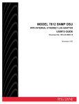
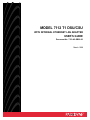
MODEL 7112 T1 DSU/CSU
WITH INTERNAL ETHERNET LAN ADAPTER
USER’S GUIDE
Document No. 7112-A2-GB20-20
March 1998
Copyright 1998 Paradyne Corporation.
All rights reserved.
Printed in U.S.A.
Notice
This publication is protected by federal copyright law. No part of this publication may be copied or distributed,
transmitted, transcribed, stored in a retrieval system, or translated into any human or computer language in any form
or by any means, electronic, mechanical, magnetic, manual or otherwise, or disclosed to third parties without the
express written permission of Paradyne Corporation, 8545 126th Avenue North, P.O. Box 2826, Largo,
Florida 33779-2826.
Paradyne Corporation makes no representation or warranties with respect to the contents hereof and specifically
disclaims any implied warranties of merchantability or fitness for a particular purpose. Further, Paradyne Corporation
reserves the right to revise this publication and to make changes from time to time in the contents hereof without
obligation of Paradyne Corporation to notify any person of such revision or changes.
Changes and enhancements to the product and to the information herein will be documented and issued as a new
release to this manual.
Trademarks
All products and services mentioned herein are the trademarks, service marks, registered trademarks or registered
service marks of their respective owners.
Warranty, Sales, and Service Information
Contact your local sales representative, service representative, or distributor directly for any help needed. For
additional information concerning warranty, sales, service, repair, installation, documentation, training, distributor
locations, or Paradyne worldwide office locations, use one of the following methods:
Via the Internet: Visit the Paradyne World Wide Web site at http://www.paradyne.com
Via Telephone: Call our automated call system to receive current information via fax or to speak with a
company representative.
— Within the U.S.A., call 1-800-870-2221
— Outside the U.S.A., call 1-727-530-2340
Printed on recycled paper
A
March 1998
7112-A2-GB20-20
Contents
About This Guide
Document Purpose and Intended Audience . . . . . . . . . . . . . . . . . . . . . . . . . vii
Document Summary . . . . . . . . . . . . . . . . . . . . . . . . . . . . . . . . . . . . . . . . . . . . . vii
Product-Related Documents . . . . . . . . . . . . . . . . . . . . . . . . . . . . . . . . . . . . . . viii
1
About the T1 DSU/CSU
Model 7112 T1 DSU/CSU Features . . . . . . . . . . . . . . . . . . . . . . . . . . . . . . . . 1-1
Typical DSU/CSU Configurations . . . . . . . . . . . . . . . . . . . . . . . . . . . . . . . . . . 1-2
User Interface Types . . . . . . . . . . . . . . . . . . . . . . . . . . . . . . . . . . . . . . . . . . . . 1-3
Front Panel LED Status Indicators . . . . . . . . . . . . . . . . . . . . . . . . . . . . . . . . . 1-3
Rear Panel Interface Connections . . . . . . . . . . . . . . . . . . . . . . . . . . . . . . . . . 1-4
SNMP Management Capabilities . . . . . . . . . . . . . . . . . . . . . . . . . . . . . . . . . . 1-4
Management Information Base (MIB) Support . . . . . . . . . . . . . . . . . . . 1-4
2
Using the ASCII Terminal Interface (ATI)
Accessing the ATI . . . . . . . . . . . . . . . . . . . . . . . . . . . . . . . . . . . . . . . . . . . . . . . 2-1
Connecting to the Terminal Port . . . . . . . . . . . . . . . . . . . . . . . . . . . . . . . . . . . 2-1
Initiating an ATI Session . . . . . . . . . . . . . . . . . . . . . . . . . . . . . . . . . . . . . . . . . 2-2
Screen Work Areas . . . . . . . . . . . . . . . . . . . . . . . . . . . . . . . . . . . . . . . . . . . . . 2-3
Screen Format Types . . . . . . . . . . . . . . . . . . . . . . . . . . . . . . . . . . . . . . . . . . . . 2-3
What Affects Screen Displays . . . . . . . . . . . . . . . . . . . . . . . . . . . . . . . . . 2-3
Navigating . . . . . . . . . . . . . . . . . . . . . . . . . . . . . . . . . . . . . . . . . . . . . . . . . . . . . 2-4
Keyboard Keys . . . . . . . . . . . . . . . . . . . . . . . . . . . . . . . . . . . . . . . . . . . . . . 2-4
Screen Function Keys . . . . . . . . . . . . . . . . . . . . . . . . . . . . . . . . . . . . . . . . 2-6
Switching Between Screen Work Areas . . . . . . . . . . . . . . . . . . . . . . . . 2-6
Ending an ATI Session . . . . . . . . . . . . . . . . . . . . . . . . . . . . . . . . . . . . . . . . . . . 2-7
7112-A2-GB20-20
March 1998
i
Contents
3
Configuring the DSU/CSU
Entering Device and System Information . . . . . . . . . . . . . . . . . . . . . . . . . . . 3-1
Configuring the DSU/CSU . . . . . . . . . . . . . . . . . . . . . . . . . . . . . . . . . . . . . . . . 3-2
Configuration Option Areas . . . . . . . . . . . . . . . . . . . . . . . . . . . . . . . . . . . 3-2
Accessing and Displaying Configuration Options . . . . . . . . . . . . . . . . 3-3
Saving Configuration Options . . . . . . . . . . . . . . . . . . . . . . . . . . . . . . . . . 3-3
Assigning DS0 Channels to the Data Port . . . . . . . . . . . . . . . . . . . . . . . . . . 3-4
Displaying DS0 Channel Assignments . . . . . . . . . . . . . . . . . . . . . . . . . . . . . 3-5
Using the Block or ACAMI Assignment Method . . . . . . . . . . . . . . . . . . 3-5
Using the Individual Channel Assignment Method . . . . . . . . . . . . . . . 3-6
Clearing DS0 Channel Assignments . . . . . . . . . . . . . . . . . . . . . . . . . . . 3-6
4
Security
Overview . . . . . . . . . . . . . . . . . . . . . . . . . . . . . . . . . . . . . . . . . . . . . . . . . . . . . . 4-1
Creating a Login . . . . . . . . . . . . . . . . . . . . . . . . . . . . . . . . . . . . . . . . . . . . . 4-2
Deleting a Login . . . . . . . . . . . . . . . . . . . . . . . . . . . . . . . . . . . . . . . . . . . . . 4-3
Resetting the DSU/CSU’s COM Port or Factory Defaults . . . . . . . . . . 4-3
ATI Access . . . . . . . . . . . . . . . . . . . . . . . . . . . . . . . . . . . . . . . . . . . . . . . . . 4-4
Effective Access Level . . . . . . . . . . . . . . . . . . . . . . . . . . . . . . . . . . . . . . . 4-5
Controlling SNMP Access . . . . . . . . . . . . . . . . . . . . . . . . . . . . . . . . . . . . . . . . 4-6
Assigning SNMP Community Names and Access Levels . . . . . . . . . 4-6
Limiting SNMP Access through the IP Addresses . . . . . . . . . . . . . . . . 4-7
5
IP Addressing
IP Addressing . . . . . . . . . . . . . . . . . . . . . . . . . . . . . . . . . . . . . . . . . . . . . . . . . . 5-1
IP Addressing Examples . . . . . . . . . . . . . . . . . . . . . . . . . . . . . . . . . . . . . . . . . 5-2
Local Addressing Only (No FDL) . . . . . . . . . . . . . . . . . . . . . . . . . . . . . . 5-2
FDL Connection – Extending Subnet for FDL . . . . . . . . . . . . . . . . . . . 5-3
FDL Connection – Unique FDL Subnet . . . . . . . . . . . . . . . . . . . . . . . . . 5-4
Assigning IP Addresses and Subnet Masks . . . . . . . . . . . . . . . . . . . . . . . . . 5-5
ii
March 1998
7112-A2-GB20-20
Contents
6
Monitoring the DSU/CSU
What to Monitor . . . . . . . . . . . . . . . . . . . . . . . . . . . . . . . . . . . . . . . . . . . . . . . . . 6-1
DSU/CSU LEDs . . . . . . . . . . . . . . . . . . . . . . . . . . . . . . . . . . . . . . . . . . . . . . . . 6-2
System LEDs . . . . . . . . . . . . . . . . . . . . . . . . . . . . . . . . . . . . . . . . . . . . . . . 6-3
Network LEDs . . . . . . . . . . . . . . . . . . . . . . . . . . . . . . . . . . . . . . . . . . . . . . 6-4
Port LEDs . . . . . . . . . . . . . . . . . . . . . . . . . . . . . . . . . . . . . . . . . . . . . . . . . . 6-5
Status Screen Commands . . . . . . . . . . . . . . . . . . . . . . . . . . . . . . . . . . . . . . . 6-6
System and Test Status . . . . . . . . . . . . . . . . . . . . . . . . . . . . . . . . . . . . . . . . . . 6-6
Health and Status Messages . . . . . . . . . . . . . . . . . . . . . . . . . . . . . . . . . . 6-7
Self-Test Results . . . . . . . . . . . . . . . . . . . . . . . . . . . . . . . . . . . . . . . . . . . . 6-8
Test Status Messages . . . . . . . . . . . . . . . . . . . . . . . . . . . . . . . . . . . . . . . . 6-9
Cross Connect Status . . . . . . . . . . . . . . . . . . . . . . . . . . . . . . . . . . . . . . . . . . . 6-10
Network Performance Statistics . . . . . . . . . . . . . . . . . . . . . . . . . . . . . . . . . . . 6-11
Summary Information . . . . . . . . . . . . . . . . . . . . . . . . . . . . . . . . . . . . . . . . 6-12
Interval Table . . . . . . . . . . . . . . . . . . . . . . . . . . . . . . . . . . . . . . . . . . . . . . . 6-12
Worst Interval . . . . . . . . . . . . . . . . . . . . . . . . . . . . . . . . . . . . . . . . . . . . . . . 6-13
24-Hour Totals . . . . . . . . . . . . . . . . . . . . . . . . . . . . . . . . . . . . . . . . . . . . . . 6-14
Ethernet Port Status . . . . . . . . . . . . . . . . . . . . . . . . . . . . . . . . . . . . . . . . . . . . . 6-14
Management Protocol Statistics . . . . . . . . . . . . . . . . . . . . . . . . . . . . . . . . . . . 6-15
7
Testing
Detecting Problems . . . . . . . . . . . . . . . . . . . . . . . . . . . . . . . . . . . . . . . . . . . . . 7-1
Accessing the Test Menu . . . . . . . . . . . . . . . . . . . . . . . . . . . . . . . . . . . . . . . . . 7-2
Running Network Tests . . . . . . . . . . . . . . . . . . . . . . . . . . . . . . . . . . . . . . . . . . 7-3
Line Loopback . . . . . . . . . . . . . . . . . . . . . . . . . . . . . . . . . . . . . . . . . . . . . . 7-4
Payload Loopback . . . . . . . . . . . . . . . . . . . . . . . . . . . . . . . . . . . . . . . . . . . 7-4
Repeater Loopback . . . . . . . . . . . . . . . . . . . . . . . . . . . . . . . . . . . . . . . . . . 7-5
Remote Send Line Loopback . . . . . . . . . . . . . . . . . . . . . . . . . . . . . . . . . 7-6
Test Patterns for the Network . . . . . . . . . . . . . . . . . . . . . . . . . . . . . . . . . 7-6
Running Data Port Tests . . . . . . . . . . . . . . . . . . . . . . . . . . . . . . . . . . . . . . . . . 7-7
Data Terminal Loopback . . . . . . . . . . . . . . . . . . . . . . . . . . . . . . . . . . . . . . 7-8
Data Channel Loopback . . . . . . . . . . . . . . . . . . . . . . . . . . . . . . . . . . . . . . 7-9
Send V.54 Up/Down Sequences . . . . . . . . . . . . . . . . . . . . . . . . . . . . . . . 7-10
Send FT1 Up/Down Sequences . . . . . . . . . . . . . . . . . . . . . . . . . . . . . . . 7-11
Test Patterns for the DTE . . . . . . . . . . . . . . . . . . . . . . . . . . . . . . . . . . . . . 7-11
Lamp Test . . . . . . . . . . . . . . . . . . . . . . . . . . . . . . . . . . . . . . . . . . . . . . . . . . . . . . 7-12
Ending an Active Test . . . . . . . . . . . . . . . . . . . . . . . . . . . . . . . . . . . . . . . . . . . . 7-12
7112-A2-GB20-20
March 1998
iii
Contents
8
Messages and Troubleshooting
Overview . . . . . . . . . . . . . . . . . . . . . . . . . . . . . . . . . . . . . . . . . . . . . . . . . . . . . . 8-1
SNMP Traps . . . . . . . . . . . . . . . . . . . . . . . . . . . . . . . . . . . . . . . . . . . . . . . . . . . 8-1
Configuring SNMP Traps . . . . . . . . . . . . . . . . . . . . . . . . . . . . . . . . . . . . . 8-1
Device Messages . . . . . . . . . . . . . . . . . . . . . . . . . . . . . . . . . . . . . . . . . . . . . . . 8-2
Troubleshooting . . . . . . . . . . . . . . . . . . . . . . . . . . . . . . . . . . . . . . . . . . . . . . . . . 8-4
A
Configuration Option Tables
Overview . . . . . . . . . . . . . . . . . . . . . . . . . . . . . . . . . . . . . . . . . . . . . . . . . . . . . . A-1
System Options Menu . . . . . . . . . . . . . . . . . . . . . . . . . . . . . . . . . . . . . . . . . . . A-2
Network Interface Options Menu . . . . . . . . . . . . . . . . . . . . . . . . . . . . . . . . . . A-3
Cross Connect Assignments . . . . . . . . . . . . . . . . . . . . . . . . . . . . . . . . . . . . . . A-7
Data Port Options Menu . . . . . . . . . . . . . . . . . . . . . . . . . . . . . . . . . . . . . . . . . A-8
Ethernet Port Options Menu . . . . . . . . . . . . . . . . . . . . . . . . . . . . . . . . . . . . . . A-11
Terminal Port Options . . . . . . . . . . . . . . . . . . . . . . . . . . . . . . . . . . . . . . . . . . . . A-12
Telnet Session Options . . . . . . . . . . . . . . . . . . . . . . . . . . . . . . . . . . . . . . . . . . A-14
SNMP Menu . . . . . . . . . . . . . . . . . . . . . . . . . . . . . . . . . . . . . . . . . . . . . . . . . . . A-16
General SNMP Management Options . . . . . . . . . . . . . . . . . . . . . . . . . . A-16
SNMP NMS Security Options . . . . . . . . . . . . . . . . . . . . . . . . . . . . . . . . . A-17
SNMP Traps Options . . . . . . . . . . . . . . . . . . . . . . . . . . . . . . . . . . . . . . . . A-19
B
Worksheets
Overview . . . . . . . . . . . . . . . . . . . . . . . . . . . . . . . . . . . . . . . . . . . . . . . . . . . . . . B-1
Configuration Worksheets . . . . . . . . . . . . . . . . . . . . . . . . . . . . . . . . . . . . . . . . B-1
iv
March 1998
7112-A2-GB20-20
Contents
C
MIB Descriptions
Overview . . . . . . . . . . . . . . . . . . . . . . . . . . . . . . . . . . . . . . . . . . . . . . . . . . . . . . C-1
MIB II – RFC 1213 and RFC 1573 . . . . . . . . . . . . . . . . . . . . . . . . . . . . . . . . . C-1
System Group . . . . . . . . . . . . . . . . . . . . . . . . . . . . . . . . . . . . . . . . . . . . . . C-2
Interfaces Group . . . . . . . . . . . . . . . . . . . . . . . . . . . . . . . . . . . . . . . . . . . . C-3
Extension to Interface Table (ifXTable) . . . . . . . . . . . . . . . . . . . . . . . . . C-7
Interface Stack Group . . . . . . . . . . . . . . . . . . . . . . . . . . . . . . . . . . . . . . . . C-8
Interface Test Table . . . . . . . . . . . . . . . . . . . . . . . . . . . . . . . . . . . . . . . . . . C-9
Generic Receive Address Table . . . . . . . . . . . . . . . . . . . . . . . . . . . . . . . C-9
IP Group . . . . . . . . . . . . . . . . . . . . . . . . . . . . . . . . . . . . . . . . . . . . . . . . . . . C-9
SNMP Group . . . . . . . . . . . . . . . . . . . . . . . . . . . . . . . . . . . . . . . . . . . . . . . C-12
DS1/E1 – RFC 1406 . . . . . . . . . . . . . . . . . . . . . . . . . . . . . . . . . . . . . . . . . . . . . C-13
DS1 Near End Group Configuration Table Objects . . . . . . . . . . . . . . . C-13
DS1 Near End Group Current Table Objects . . . . . . . . . . . . . . . . . . . . C-17
DS1 Near End Group Interval Table Objects . . . . . . . . . . . . . . . . . . . . C-18
DS1 Near End Group Total Table Objects . . . . . . . . . . . . . . . . . . . . . . . C-19
DS1 Fractional Group . . . . . . . . . . . . . . . . . . . . . . . . . . . . . . . . . . . . . . . . C-20
Ethernet-Like MIB – RFC 1643 . . . . . . . . . . . . . . . . . . . . . . . . . . . . . . . . . . . C-20
RS-232-Like MIB – RFC 1659 . . . . . . . . . . . . . . . . . . . . . . . . . . . . . . . . . . . . C-20
Number of RS-232-Like Ports Object . . . . . . . . . . . . . . . . . . . . . . . . . . . C-20
General Port Table Objects . . . . . . . . . . . . . . . . . . . . . . . . . . . . . . . . . . . C-20
Asynchronous Port Table Objects . . . . . . . . . . . . . . . . . . . . . . . . . . . . . . C-22
Synchronous Port Table Objects . . . . . . . . . . . . . . . . . . . . . . . . . . . . . . . C-23
Input Signal Table Objects . . . . . . . . . . . . . . . . . . . . . . . . . . . . . . . . . . . . C-24
Output Signal Table Objects . . . . . . . . . . . . . . . . . . . . . . . . . . . . . . . . . . C-25
Generic Interface Extension MIB – RFC 1229 . . . . . . . . . . . . . . . . . . . . . . . C-26
Generic Interface Test Table Objects . . . . . . . . . . . . . . . . . . . . . . . . . . . C-26
Enterprise MIB Object . . . . . . . . . . . . . . . . . . . . . . . . . . . . . . . . . . . . . . . . . . . C-29
Device Configuration Variable (pdn-common 7) . . . . . . . . . . . . . . . . . . C-29
Device Security, pdn-security (pdn-common 8) . . . . . . . . . . . . . . . . . . C-29
Device Traps, pdn-traps (pdn-common 9) . . . . . . . . . . . . . . . . . . . . . . . C-29
Device Control, pdn-control (pdn-common 10) . . . . . . . . . . . . . . . . . . . C-29
7112-A2-GB20-20
March 1998
v
Contents
D
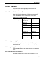
Standards Compliance for SNMP Traps
Overview . . . . . . . . . . . . . . . . . . . . . . . . . . . . . . . . . . . . . . . . . . . . . . . . . . . . . . D-1
Trap: warmStart . . . . . . . . . . . . . . . . . . . . . . . . . . . . . . . . . . . . . . . . . . . . . . . . . D-1
Trap: authentificationFailure . . . . . . . . . . . . . . . . . . . . . . . . . . . . . . . . . . . . . . D-1
Traps: linkUp and linkDown . . . . . . . . . . . . . . . . . . . . . . . . . . . . . . . . . . . . . . . D-2
Traps: enterpriseSpecific . . . . . . . . . . . . . . . . . . . . . . . . . . . . . . . . . . . . . . . . . D-4
E
Cables and Pin Assignments
Cabling Overview . . . . . . . . . . . . . . . . . . . . . . . . . . . . . . . . . . . . . . . . . . . . . . . E-1
Modular RJ48C-to-RJ48C T1 Network Interface Cable . . . . . . . . . . . . . . . E-2
Modular RJ48C-to-CA81A T1 Network Interface Cable . . . . . . . . . . . . . . . E-2
Terminal Port EIA-232 Connector . . . . . . . . . . . . . . . . . . . . . . . . . . . . . . . . . E-3
10BaseT Connector . . . . . . . . . . . . . . . . . . . . . . . . . . . . . . . . . . . . . . . . . . . . . E-3
Serial Crossover Cable . . . . . . . . . . . . . . . . . . . . . . . . . . . . . . . . . . . . . . . . . . E-4
DTE V.35 Connector . . . . . . . . . . . . . . . . . . . . . . . . . . . . . . . . . . . . . . . . . . . . . E-5
F
Technical Specifications
Glossary
Index
vi
March 1998
7112-A2-GB20-20
About This Guide
Document Purpose and Intended Audience
This guide contains information needed to set up, configure, and operate the
Model 7112 T1 DSU/CSU and is intended for use by installers and operators.
Document Summary
7112-A2-GB20-20
Section
Description
Chapter 1
About the T1 DSU/CSU. Describes the DSU/CSU features
and SNMP management capabilities with a typical
configuration example.
Chapter 2
Using the ASCII Terminal Interface. Provides instructions for
accessing the user interface and navigating the screens.
Chapter 3
Configuring the DSU/CSU. Provides procedures for setting
up the user interface, and DSU/CSU configuration steps.
Chapter 4
Security. Presents procedures for creating a login, setting
the effective access levels, and controlling SNMP access.
Chapter 5
IP Addressing. Provides details regarding IP addresses with
examples.
Chapter 6
Monitoring the DSU/CSU. Describes monitoring details
about the LEDs, DSU/CSU status, and network statistics.
Chapter 7
Testing. Provides details about available tests and test
setup.
Chapter 8
Messages and Troubleshooting. Provides information on
SNMP traps, device messages, and troubleshooting.
March 1998
vii
About This Guide
Section
Description
Appendix A
Configuration Option Tables. Contains all configuration
options, default settings, and possible settings.
Appendix B
Worksheets. Contains all the configuration options, default
settings, and possible settings to use for planning.
Appendix C
MIB Descriptions. Provides all MIBs supported by the
DSU/CSU.
Appendix D
Standards Compliance for SNMP Traps. Contains SNMP
trap compliance details.
Appendix E
Cables and Pin Assignments. Contains connector and
interface details.
Appendix F
Technical Specifications. Contains physical and regulatory
specifications, network and port interfaces, power
consumption values, etc.
Glossary
Defines acronyms and terms used in this document.
Index
Lists key terms, acronyms, concepts, and sections in
alphabetical order.
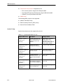
Product-Related Documents
Document Number
Document Title
7112-A2-GN10
Model 7112 T1 DSU/CSU with Internal Ethernet LAN
Adapter Startup Instructions
Contact your sales or service representative to order additional product
documentation.
Paradyne documents are also available on the World Wide Web at:
http://www.paradyne.com
Select Service & Support → Technical Manuals
viii
March 1998
7112-A2-GB20-10
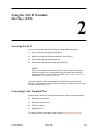
About the T1 DSU/CSU
1
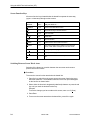
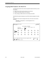
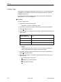
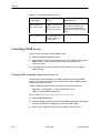
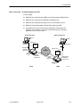
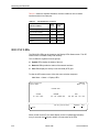
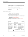
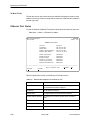
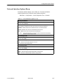
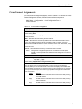
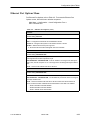
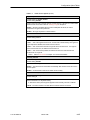
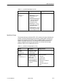
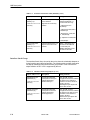
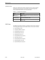
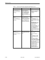
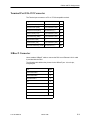
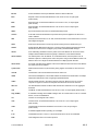
Model 7112 T1 DSU/CSU Features
SNMP
D S U /C S U
NMS
LA N A
10B aseT
C onnection
R outer
T1
N et w o r k
LA N B
R outer
SNMP
D S U /C S U
Facility
D ata Link
97-15692
The 7112 T1 DSU/CSU provides an interface between the T1 digital network and
the customer premises equipment, converting signals received from the DTE
(Data Terminal Equipment) to bipolar signals that can be transmitted over T1
lines.
The T1 DSU/CSU offers these features:
7112-A2-GB20-20
10BaseT Port. Allows the DSU/CSU to connect directly to an Ethernet LAN.
SNMP ( Simple Network Management Protocol ) Management. Provides
network management via an industry-standard SNMP management system.
Facility Data Link (FDL). Provides remote management via SNMP or Telnet
session capability over the T1 network.
ASCII Terminal Interface (ATI). Provides a menu-driven VT100-compatible
interface for configuring and managing the DSU/CSU locally or remotely by
Telnet session or External Modem.
Two Customer-Specified Configuration Storage Areas. Allows quick
access to alternate sets of configuration options.
March 1998
1-1
About the T1 DSU/CSU
Management. Provides management via:
— ASCII terminal connection through the Terminal port
— External modem through the Terminal port
— Telnet through the Ethernet port or the FDL
— SNMP through Ethernet port or the FDL
Alarm Indication. Activates front panel LEDs.
Diagnostics. Provides the capability to diagnose device and network
problems and perform tests, including digital loopbacks, pattern tests, and
self-test.
Device and Test Monitoring. Provides the capability of tracking and
evaluating the unit’s operation, including health and status, and error-rate
monitoring.
Security. Provides multiple levels of security, which deters unauthorized
access to the DSU/CSU.
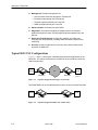
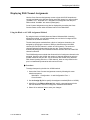
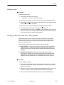
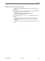
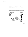
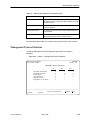
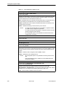
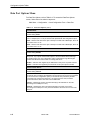
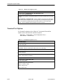
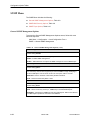
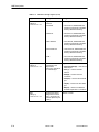
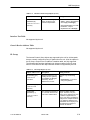
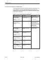
Typical DSU/CSU Configurations
Figures 1-1 and 1-2 show typical LAN/WAN interconnection applications for the
DSU/CSU. The routers connected to the DSU/CSU at each location provide the
LAN interconnection.
Router
Router
T1
DSU/CSU
DSU/CSU
98-15688-01
Figure 1-1. Typical Configuration (through a T1 network)
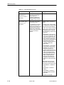
Two SNMP DSUs can be connected back-to-back to act as Local Area Data Sets.
Router
Router
DSU/CSU
DSU/CSU
98-15697-01
Figure 1-2. Typical Configuration (DSU/CSU to DSU/CSU)
1-2
March 1998
7112-A2-GB20-20
About the T1 DSU/CSU
User Interface Types
There are three types of user interfaces to the T1 DSU/CSU:
Menu-driven ASCII terminal interface screens (see Chapter 2, Using the
ASCII Terminal Interface (ATI)).
SNMP NMS Access – Refer to Model 7112 T1 DSU/CSU Features on
page 1-1. Provides the capability to access the DSU/CSU via an SNMP
management system connected to the Ethernet port or remotely through the
Facility Data Link (FDL). Refer to Chapter 5, IP Addressing.
Front panel LED status indicators. Refer to Chapter 6, Monitoring the
DSU/CSU.
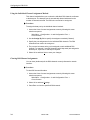
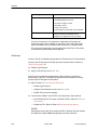
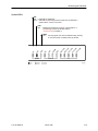
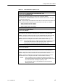
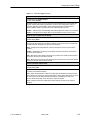
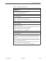
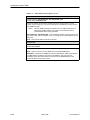
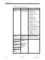
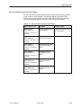
Front Panel LED Status Indicators
FT1/T1
System
)
)
08
06
(1
TR
D
TS
(1
)
C
RT
S
(1
05
04
(1
XD
R
D
(1
Network
TX
R
EE
F
AR
O
AL
O
ST
G
SI
TE
K
FA
I
Out
O
In
L
M
03
)
7112 SNMP DSU/CSU
MONITOR
)
Refer to Chapter 6, Monitoring DSU/CSU LEDs.
Port
97-15687
Figure 1-3. Model 7112 SNMP DSU/CSU Front Panel
7112-A2-GB20-20
March 1998
1-3
About the T1 DSU/CSU
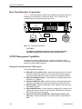
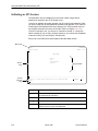
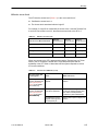
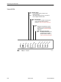
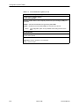
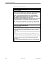
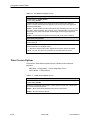
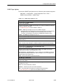
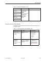
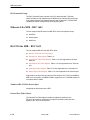
Rear Panel Interface Connections
Figure 1-4 shows the physical interfaces of the DSU/CSU. Information about the
installation of the DSU/CSU is contained in Model 7112 T1 DSU/CSU with
Internal Ethernet LAN Adapter Startup Instructions.
10BaseT
POWER
NETWORK
TERMINAL
D
T
E
Ethernet
or
Modem
DTE
T1
Network
Terminal
97-15694
Figure 1-4. Rear Panel Connectors
CAUTION:
The 10BaseT and Network connectors are not keyed. Follow the
installation procedures carefully to avoid connection errors.
SNMP Management Capabilities
The DSU/CSU supports SNMP Version 1, and has the capability of being
managed by any industry-standard SNMP manager and accessed using SNMP
protocol by external SNMP managers.
Management Information Base (MIB) Support
The following MIBs are supported:
1-4
MIB II (RFC 1213 and RFC 1573) – Defines the general objects for use with
a network management protocol in TCP/IP internets and provides general
information about the DSU/CSU. MIB II is backward-compatible with MIB I.
Ethernet-like MIB (RFC 1643) – Defines objects for managing Ethernet-like
interfaces (e.g., 10BaseT).
RS-232-Like MIB (RFC 1659) – Defines objects for managing RS-232-type
interfaces and supports the V.35 synchronous data port on the DSU/CSU.
Enterprise MIB – Supports configuration, status, statistics, and tests on the
DS1 network interface.
DS1/E1 MIB (RFC1406) – Defines objects for managing DS1 interfaces and
supports the network interface on the DSU/CSU. DS1 Near End Group and
DS1 Fractional Group are supported.
Generic-Interface Extension MIB (RFC 1229) (Generic Interface Test
table only) – Provides extensions to the generic interface group defined in
MIB II.
March 1998
7112-A2-GB20-20
Using the ASCII Terminal
Interface (ATI)
2
Accessing the ATI
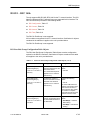
You can communicate with the ATI using one of the following methods:
Direct connection through the Terminal port.
Dialing in through an external modem to the Terminal port.
Telnet session through the Ethernet port.
Telnet session through the Facility Data Link (FDL).
NOTE:
Only one ATI session can be active at a time, and another user’s session
cannot be forced to end. To automatically log out a user due to inactivity,
enable the Inactivity Timeout option (see Table A-6, Terminal Port Options
and Table A-7, Telnet Session Options).
The user interface is blank until activated. Press Enter to activate the user
interface. Security can limit ATI access several ways. To setup security or a login
ID, refer to Chapter 4, Security.
Connecting to the Terminal Port
Ensure that the device you connect communicates using the following settings:
Data rate set to 9.6 kbps.
Character length set to 8.
Parity set to None.
Stop Bits set to 1.
To change Terminal port settings, refer to Table A-6, Terminal Port Options.
7112-A2-GB20-20
March 1998
2-1
Using the ASCII Terminal Interface (ATI)
Initiating an ATI Session
The Main Menu screen is displayed on the screen unless a login ID and
password is required or the ATI is already in use.
If security is enabled, the system prompts you for a login ID and password. After
you enter a valid login ID and password, the Main menu appears. If you enter an
invalid login ID and password after three attempts, the Telnet session closes or
the terminal connection returns to an idle state. Refer to Chapter 4, Security.
If the ATI is already in use, you will see a “connection refused” or “connection
failed” message (if you are using a Telnet session) or you will see the IP address
of the other user (if you are using the Terminal port).
Entry to all of the DSU/CSU’s tasks begins at the Main Menu screen.
Menu Path
ÎÎÎÎÎÎÎÎÎÎÎÎÎÎÎÎÎÎÎÎÎÎÎÎÎ
ÎÎÎÎÎÎÎÎÎÎÎÎÎÎÎÎÎÎÎÎÎÎÎÎÎ
ÎÎÎÎÎÎÎÎÎÎÎÎÎÎÎÎÎÎÎÎÎÎÎÎÎ
ÎÎÎÎÎÎÎÎÎÎÎÎÎÎÎÎÎÎÎÎÎÎÎÎÎ
ÎÎÎÎÎÎÎÎÎÎÎÎÎÎÎÎÎÎÎÎÎÎÎÎÎ
ÎÎÎÎÎÎÎÎÎÎÎÎÎÎÎÎÎÎÎÎÎÎÎÎÎ
ÎÎÎÎÎÎÎÎÎÎÎÎÎÎÎÎÎÎÎÎÎÎÎÎÎ
ÎÎÎÎÎÎÎÎÎÎÎÎÎÎÎÎÎÎÎÎÎÎÎÎÎ
ÎÎÎÎÎÎÎÎÎÎÎÎÎÎÎÎÎÎÎÎÎÎÎÎÎ
ÎÎÎÎÎÎÎÎÎÎÎÎÎÎÎÎÎÎÎÎÎÎÎÎÎ
ÎÎÎÎÎÎÎÎÎÎÎÎÎÎÎÎÎÎÎÎÎÎÎÎÎ
ÎÎÎÎÎÎÎÎÎÎÎÎÎÎÎÎÎÎÎÎÎÎÎÎÎ
ÎÎÎÎÎÎÎÎÎÎÎÎÎÎÎÎÎÎÎÎÎÎÎÎÎ
ÎÎÎÎÎÎÎÎÎÎÎÎÎÎÎÎÎÎÎÎÎÎÎÎÎ
ÎÎÎÎÎÎÎÎÎÎÎÎÎÎÎÎÎÎÎÎÎÎÎÎÎ
ÎÎÎÎÎÎÎÎÎÎÎÎÎÎÎÎÎÎÎÎÎÎÎÎÎ
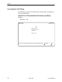
main
Device Name:
PARADYNE
Model: 7112
MAIN MENU
Screen
Area
Screen
Function
Keys
Status
Test
Configuration
Control
Input Fields
––––––––––––––––––––––––––––––––––––––––––––––––––––––––––––––––––––––––––––––––
Ctrl-a to access these functions, ESC for previous menu
MainMenu
Exit
Save
Select . . .
To . . .
Status
View system status, diagnostic test results, cross connections, statistics,
and LEDs identity information.
Test
Select and cancel tests for the DSU/CSU’s interfaces.
Configuration Display and edit the configuration options.
Control
2-2
Control the user interface for device naming, login administration, or to
initiate a power-up reset of the DSU/CSU.
March 1998
7112-A2-GB20-20
Using the ASCII Terminal Interface (ATI)
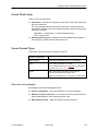
Screen Work Areas
There are two user work areas:
Screen area – Provides the menu path, access level, menus, and input fields
above the dotted line.
The menu path appears as the first line on the screen. In this manual, the
menu path is presented as a menu selection sequence with the names of the
screens For example:
Main Menu → Configuration → Load Configuration From →
Edit →Terminal Port
Screen function key area – Provides functions available below the dotted
line based upon screen selection and access level.
Screen Format Types
Three types of screen formats are available on the ATI.
Use the screen format . . . To . . .
Menu selection
Display a list of available functions for user selection.
Input
Add or change information on a screen.
Input or edit fields that have an Underline in the field value
or selection. See Screen Work Areas.
Display
Display configuration information and results from
performance and DSU/CSU-specific tests.
Display-only fields that have no underline in the field value.
What Affects Screen Displays
What appears on the screens depends on the:
7112-A2-GB20-20
Current configuration – How your DSU/CSU is currently configured.
Effective security access level – An access level that is typically set by the
system administrator for each interface and each user.
Data selection criteria – What you entered in previous screens.
March 1998
2-3
Using the ASCII Terminal Interface (ATI)
Navigating
You can navigate the screens by:
Using keyboard keys
Using screen function keys
Switching between the two screen work areas
MAIN MENU
Status
Test
Configuration
Control
Load Configuration
from . . .
Status
Test
• System and Test Status
• Network Performance Statistics
• Cross Connect Status
• Ethernet Port Status
• Network Tests
• Data Port Tests
• Lamp Test
• Abort Tests
• Management Protocol Satistics
• Display LEDs
• Identity
Configuration
Edit/Display
• System
• Network
• Cross Connect
• Data Port
Control
• Device Name
• Administer Logins
• Reset Device
• Ethernet Port
• Terminal Port
• Telnet Session
• SNMP
SNMP
• General SNMP Management
• SNMP NMS Security
• SNMP Traps
97-15686
Keyboard Keys
Use the following keyboard keys to navigate within the screen.
2-4
Press . . .
To . . .
Ctrl-a
Move cursor between the screen area and the screen function
keys area below the dotted line at the bottom of the screen.
Esc
Return to the previous screen.
Tab
Move cursor to the next field on the screen.
Backspace
Move cursor to the previous field on the screen.
March 1998
7112-A2-GB20-20
Using the ASCII Terminal Interface (ATI)
Press . . .
To . . .
Enter
Accept entry or display valid options on the last row of the screen
when pressed before entering data or after entering invalid data.
Ctrl-k
Tab backwards (moves cursor one field to the left).
Spacebar
Select the next valid value for the field.
Delete (Del)
Delete character that the cursor is on.
Up Arrow or Ctrl-u
Move cursor up one field within a column on the same screen.
Down Arrow or Ctrl-d Move cursor down one field within a column on the same screen.
Right Arrow or Ctrl-f
Move cursor one character to the right if in edit mode.
Left Arrow or Ctrl-b
Move cursor one character to the left if in edit mode.
Ctrl-l
Redraw the screen display, clearing information typed in but not
yet entered.
" Procedure
To make a menu or field selection:
1. Press the tab key or the right arrow key to position the cursor on a menu or
field selection. Each selection is highlighted as you press the key to move the
cursor from position to position.
2. Press Enter. The selected menu or screen appears.
3. Continue Steps 1 and 2 until you reach the screen you want.
The current setting or value appears to the right of the field name. You can enter
information into a selected field by:
H
Typing in the first letter(s) of a field value or command, using the DSU/CSU’s
character matching feature.
H
Switching from the screen area to the screen function area below the dotted
line and selecting or entering the designated screen function key.
If a field is blank and the Field Values screen area displays valid selections, press
the spacebar and the first valid value for the field will appear. Continue pressing
the spacebar to scroll through other valid values.
7112-A2-GB20-20
March 1998
2-5
Using the ASCII Terminal Interface (ATI)
Screen Function Keys
All screen function keys located below the dotted line operate the same way
(upper- or lowercase) throughout the screens.
For the screen
Select . . . And press Enter to . . .
function . . .
MainMenu
M or m
Return to the Main Menu screen.
Exit
E or e
Terminate the async terminal session.
New
N or n
Enter new data.
De l ete
L or l
Delete data.
Save
S or s
Save information.
Refresh
R or r
Update screen with current information.
ClrStats
C or c
Clear network performance statistics and refresh the
screen, Clear status messages for one-time events.
PgUp
U or u
Display the previous page.
PgDn
D or d
Display the next page.
ResetMon
R or r
Reset an active Monitor of active pattern test counter to
zero.
Switching Between Screen Work Areas
Selecting Ctrl-a allows you to switch between the two screen work areas to
perform all screen functions.
Procedure
To access the screen function area below the dotted line:
1. Press Ctrl-a to switch from the screen area to the screen function key area
below the dotted line. The available selections for the first input field appear
on the last line as shown below.
2. Select either the function’s designated (underlined) character or press the tab
key until you reach the desired function key.
Example:
To save the changes you have made on this screen, enter s or S ( Save).
3. Press Enter.
4. To return to the screen area above the dotted line, press Ctrl-a again.
2-6
March 1998
7112-A2-GB20-20
Using the ASCII Terminal Interface (ATI)
Ending an ATI Session
Use the Exit function key from any screen to terminate the session.
Procedure
To end a session with the ASCII terminal interface:
1. Press Ctrl-a to go to the screen function key area below the dotted line.
2. Tab to Exit (or type e or E) and press Enter. The User Interface Idle screen
appears.
7112-A2-GB20-20
March 1998
2-7
Using the ASCII Terminal Interface (ATI)
This page intentionally left blank.
2-8
March 1998
7112-A2-GB20-20
Configuring the DSU/CSU
3
Entering Device and System Information
Use the Device Name screen to determine the name that will be displayed at the
top of all ATI screens, and SNMP system information that will be displayed on the
Identity screen. To access the Device Name screen, follow this menu selection
sequence:
Main Menu → Control → Device Name
main/control/device_name
Device Name:
PARADYNE
Model: 7112
DEVICE NAME
Device
System
System
System
Î
Name:
Name:
Location:
Contact:
NE815378
lllQJ98-001
Bldg. A412, 2nd Floor, Left cabinet
Joe Smith 800-555-5555 pager 888-555-5555
Clear
Clear
Clear
Clear
ÎÎ
ÎÎ
––––––––––––––––––––––––––––––––––––––––––––––––––––––––––––––––––––––––––––––––
Ctrl-a to access these functions, ESC for previous menu
MainMenu
Exit
Save
Fields on the Device Name screen are null until you enter values. Allowable
values are any printable ASCII character except the ^ (caret).
Use the left and right arrow keys to scroll through the fields. Select Clear to reset
a field to a null value.
7112-A2-GB20-20
March 1998
3-1
Configuring the DSU/CSU
" Procedure
To enter Device Name screen information:
1. Position the cursor in the Device Name field. Enter a name unique in your
system to identify the unit.
The maximum length of Device Name is 20 characters.
2. Position the cursor in the System Name field. Enter a name unique in your
network to identify the system.
The maximum length of System Name is 255 characters.
3. Position the cursor in the System Location field. Enter the physical location of
the system.
The maximum length of System Location is 255 characters.
4. Position the cursor in the System Contact field. Enter the name and contact
information for the person responsible for the unit.
The maximum length of System Contact is 255 characters.
5. Save the Device Name screen information.
Configuring the DSU/CSU
Configuration option settings determine how the DSU/CSU operates. Use the
Configuration branch of the DSU/CSU menu to display or change configuration
option settings.
Configuration Option Areas
The DSU/CSU is shipped with factory settings in all four strap areas. You can find
default information by:
H
Referring to Appendix A, Configuration Option Tables or Appendix B,
Worksheets.
H
Accessing the Default Factory Configuration branch of the DSU/CSU menu.
The DSU/CSU has four sets of configuration option settings. The Current
Configuration matches the Default Factory Configuration until modified and saved
by the user.
Configuration Option Area
Configuration Option Set
Current Configuration
The DSU/CSU’s active set of configuration options.
Customer Configuration 1
Use to set up and store a set of configuration options for
future use.
Customer Configuration 2
Use to set up and store a second set of configuration
options for future use.
Default Factory Configuration
A read-only configuration area containing the factory
default configuration options.
If the factory default settings do not support your network’s configuration, you can
customize the configuration options for your application.
3-2
March 1998
7112-A2-GB20-20
Configuring the DSU/CSU
Accessing and Displaying Configuration Options
To display the configuration options, you must first copy one configuration option
set into the edit area.
Procedure
To load a configuration option set into the configuration edit area:
1. Follow this menu selection sequence:
Main Menu → Configuration (Load Configuration From)
2. Select the Current, Customer 1, Customer 2, or Default Factory Configuration
and press Enter.
The selected configuration option set is loaded and the Configuration
Edit/Display menu screen appears.
See Appendix A for a list and explanation of the configuration options available.
Saving Configuration Options
When changes are made to the configuration options, the changes must be
saved to take effect. The Save key and Save Configuration To screen appear
when the user has an effective access level of 1. All other effective access levels
have read-only permission.
Procedure
To save configuration options changes:
1. Press Ctrl-a to switch to the screen function key area below the dotted line.
2. Select Save and press Enter. The Save Configuration To screen appears.
3. Select one of the three configuration option areas on the screen and press
Enter. When Save is complete, Command Complete appears in the message
area at the bottom of the screen.
NOTE:
When Exit is selected before Save, a Save Configuration screen appears
requiring a Yes or No confirmation response.
7112-A2-GB20-20
If you select . . .
Then the . . .
Yes
Save Configuration To screen appears.
No
Main Menu appears and changes are not saved.
March 1998
3-3
Configuring the DSU/CSU
Assigning DS0 Channels to the Data Port
The DSU/CSU provides Cross Connect configuration options that allow you to do
the following:
Display network DS0 channels assigned to the data port.
Allocate network DS0 channels to the data port.
Clear (unassign) all DS0 channels from the data port interface.
The DSU/CSU’s default configuration has all DS0 channels assigned to the data
port.
To access the Cross Connect Assignments screen, follow this menu selection
sequence:
Main Menu → Configuration → Load Configuration From →
Cross Connect
ÎÎÎÎÎÎÎÎÎÎÎÎÎÎÎÎÎÎÎÎÎÎÎÎÎ
ÎÎÎÎÎÎÎÎÎÎÎÎÎÎÎÎÎÎÎÎÎÎÎÎÎ
ÎÎÎÎÎÎÎÎÎÎÎÎÎÎÎÎÎÎÎÎÎÎÎÎÎ
ÎÎÎÎÎÎÎÎÎÎÎÎÎÎÎÎÎÎÎÎÎÎÎÎÎ
ÎÎÎÎÎÎÎÎÎÎÎÎÎÎÎÎÎÎÎÎÎÎÎÎÎ
ÎÎÎÎÎÎÎÎÎÎÎÎÎÎÎÎÎÎÎÎÎÎÎÎÎ
ÎÎÎÎÎÎÎÎÎÎÎÎÎÎÎÎÎÎÎÎÎÎÎÎÎ
ÎÎÎÎÎÎÎÎÎÎÎÎÎÎÎÎÎÎÎÎÎÎÎÎÎ
ÎÎÎÎÎÎÎÎÎÎÎÎÎÎÎÎÎÎÎÎÎÎÎÎÎ
ÎÎÎÎÎÎÎÎÎÎÎÎÎÎÎÎÎÎÎÎÎÎÎÎÎ
ÎÎÎÎÎÎÎÎÎÎÎÎÎÎÎÎÎÎÎÎÎÎÎÎÎ
ÎÎÎÎÎÎÎÎÎÎÎÎÎÎÎÎÎÎÎÎÎÎÎÎÎ
ÎÎÎÎÎÎÎÎÎÎÎÎÎÎÎÎÎÎÎÎÎÎÎÎÎ
ÎÎÎÎÎÎÎÎÎÎÎÎÎÎÎÎÎÎÎÎÎÎÎÎÎ
ÎÎÎÎÎÎÎÎÎÎÎÎÎÎÎÎÎÎÎÎÎÎÎÎÎ
ÎÎÎÎÎÎÎÎÎÎÎÎÎÎÎÎÎÎÎÎÎÎÎÎÎ
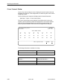
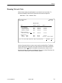
main/config/cross_connect
Device Name:
PARADYNE
Model: 7112
CROSS CONNECT ASSIGNMENTS
Assign To:
Assign By:
DS0s to Allocate:
Network
Block
24
Port Rate (Kbps): 1536
N01
P(B)
N02
P(B)
N03
P(B)
N04
P(B)
N05
P(B)
N06
P(B)
N07
P(B)
N08
P(B)
N11
P(B)
N12
P(B)
N13
P(B)
N14
P(B)
N15
P(B)
N16
P(B)
N17
P(B)
N18
P()
N19
P(B)
N20
P(B)
N21
P(B)
N22
P(B)
N23
P(B)
N24
P(B)
N25
P(B)
N26
P(B)
––––––––––––––––––––––––––––––––––––––––––––––––––––––––––––––––––––––––––––––––
Ctrl–a to access these functions, ESC for previous menu
MainMenu
Exit
Save Clrassign
Select: Block, ACAMI, Channel.
3-4
March 1998
7112-A2-GB20-20
Configuring the DSU/CSU
Displaying DS0 Channel Assignments
Use the Cross Connect Assignments screen to view which DS0 channels are
currently assigned to the data port. Below each DS0 channel you will see either
“Available” or “P”. DS0s with a “P” designation are assigned to the data port.
DS0s marked “Available” are unused (unassigned).
Cross Connect Assignments may also be displayed by accessing the Cross
Connect Status screen under the Status branch of the Main Menu.
Using the Block or ACAMI Assignment Method
By using the block or ACAMI (Alternate Channel Alternate Mark Inversion)
assignment method, you can assign a data port to a block of contiguous DS0
channels on the network interface.
The block assignment method allows a block of contiguous channels to be
assigned by specifying the number of DS0’s to allocate and an initial DS0
channel (the first DS0 channel in a block of DS0 channels). The number of
channels assigned is determined by the port rate. These channels are
automatically assigned to the destination network interface when the initial DS0
channel is selected.
The ACAMI assignment method also allows a block of contiguous channels to be
assigned. However, with ACAMI, the number of channels assigned is twice the
number needed for the port rate. This is because with ACAMI, every alternate
DS0 channel (starting with the n+1 DS0 channel), does not carry data from the
port, but instead always transmits and receives all ones.
Procedure
To assign data ports by the block or ACAMI method:
1. Access the Cross Connect Assignments screen by following this menu
selection sequence:
Main Menu → Configuration → Load Configuration From →
Cross Connect
2. Use the Assign By field to specify the assignment method (Block or ACAMI).
3. After filling in the DS0s to Allocate field, specify a port assignment for the
first DS0 channel in a block of contiguous, available DS0 channels.
4. Select Ctrl-a and then Save to save your changes.
7112-A2-GB20-20
March 1998
3-5
Configuring the DSU/CSU
Using the Individual Channel Assignment Method
This channel method allows you to select the individual DS0 channels to allocate
to the data port. The data port rate is automatically determined based on the
number of channels selected. The DS0s do not need to be contiguous.
Procedure
To assign the data port by the individual channel method:
1. Access the Cross Connect Assignments screen by following this menu
selection sequence:
Main Menu → Configuration → Load Configuration From →
Cross Connect
2. Use the Assign By field to specify the assignment method (Channel).
3. Specify the port assignments for the individual DS0 channels. The DS0
channels do not need to be contiguous.
4. The port rate increases as the port is assigned to each additional DS0
channel. For example, if two DS0 channels (at 64 kbps each) are assigned to
the data port, a port rate of 128 kbps is required.
5. Select Ctrl-a and then Save to save your changes.
Clearing DS0 Channel Assignments
You can clear (deallocate) all the DS0 channels currently allocated to network
interface.
Procedure
To clear DS0 channel allocation:
1. Access the Cross Connect Assignments screen by following this menu
selection sequence:
Main Menu → Configuration → Load Configuration From →
Cross Connect
2. Select Ctrl-a and then Clrassign.
3. Press Enter to clear the specified DS0 channels.
3-6
March 1998
7112-A2-GB20-20
Security
4
Overview
The DSU/CSU provides several methods of security by limiting user access to the
ATI through option settings. Refer to ATI Access on page 4-4.
Enable the Login Required option to require a Login ID for the:
— Terminal Port
— Telnet Session
Limit the access:
— Port Access Level option of 1, 2, or 3 for the Terminal port
— Session Access Level option of 1, 2, or 3 for the Telnet Session
Disable the access:
— Telnet Session option
— Facility Data Link (FDL) option
— Ethernet Port Use option
SNMP security is handled through Community Names with access levels and
IP address validation. Refer to Controlling SNMP Access on page 4-6.
7112-A2-GB20-20
March 1998
4-1
Security
Creating a Login
Logins apply to Terminal port and Telnet access to the ATI. Six login ID/password
combinations are available. Each Login ID and Password must be unique and
include an access level.
For additional information regarding the ATI access using the Login Required
option, refer to ATI Access on page 4-4.
Procedure
To create a login record:
1. Follow this menu selection sequence:
Main Menu → Control → Administer Logins
2. Press Ctrl-a to switch to the screen function key area below the dotted line.
3. Select New and press Enter.
4. Create the login by entering the following fields. Login IDs and passwords are
case-sensitive.
On the Administer
Logins screen, for the . . . Enter . . .
Login ID
1 to 10 ASCII printable characters
Password
1 to 10 ASCII printable characters
Access Level
Level 1, Level 2, or Level 3
NOTE:
Assign at least one Level 1 Access Level. Full access is necessary to
make configuration option changes and administer logins.
5. Press Ctrl-a to switch to the screen function key area below the dotted line.
Select Save and press Enter.
6. When Save is complete, Command Complete appears at the bottom of the
screen. Select:
— New to add another login record
— MainMenu to go to the Main Menu
— Exit to end the ATI session
4-2
March 1998
7112-A2-GB20-20
Security
Deleting a Login
" Procedure
To delete a login record:
1. Follow this menu selection sequence:
Main Menu → Control → Administer Logins
2. Press Ctrl-a to switch to the screen function key area below the dotted line.
3. Select PgUp or PgDn and press Return to page through login pages / records
until you find the one to be deleted.
4. Once the correct record is displayed, select Delete and press Enter.
5. To complete the delete action, select Save and press Enter.
When the deletion is complete, Command Complete appears at the bottom of
the screen. The number of login pages / records reflects one less record, and
the record following the deleted record appears.
Resetting the DSU/CSU’s COM Port or Factory Defaults
Misconfiguring the access unit could render the user interface inaccessible,
leaving it in a state where a session cannot be started via the COM port or a
Telnet session. If this occurs, access unit connectivity can be restored via a
directly connected terminal.
Two methods can be used to restore access to the user interface:
H
Reset COM Port – Allows you to reset the configuration options related to
COM port usage. This also causes a device reset, where the access unit
performs a Device Self-Test. No security-related configuration options are
changed.
H
Reload Factory Defaults – Allows you to reload the Default Factory
Configuration, resetting all of the configuration and control settings which
causes the current configuration to be destroyed and a device reset. This
method is also useful when the user’s password(s) have been forgotten.
" Procedure
To reset COM port settings:
1. At the async terminal that is directly connected to the access unit, configure
the terminal to operate at 9.6 kbps, using character length of 8 bits, with one
stop-bit, and no parity.
2. Reset the access unit, then immediately and repeatedly press Enter at a rate
of about 1 press per second until the System Paused screen appears.
3. Tab to the desired method, and enter yes (or y) for the selected prompt.
7112-A2-GB20-20
March 1998
4-3
Security
If entering yes to prompt . . .
Then . . .
Reset COM Port usage
Port Type is set to Terminal
Data Rate (kbps) is set to 9.6
Character Length is set to 8
Stop Bits is set to 1
Parity is set to None
External Device Commands is set to Disable
Reload Factory Defaults
All factory-loaded configuration and control
settings contained in the Default Factory
Configuration configuration area are loaded.
If no (or n) is entered, or if no selection is made within 30 seconds, the
access unit returns to the condition or operation it was in when the system
reset was initiated, with the COM port rate returning to its configured rate.
The access unit resets itself, going through a Device Self-Test. Connectivity
is restored and the Main Menu screen appears.
ATI Access
Access to the ATI is available through either the Terminal port or a Telnet session.
Access to the ATI through the Terminal port can be limited. Refer to Table A-6,
Terminal Port Options, to:
Enable Login Required.
Assign a Port Access Level of 1, 2, or 3.
The ATI can be accessed remotely through a Telnet Session via either the
Ethernet port or the FDL. The DSU/CSU provides several methods for limiting
access to the ATI through a Telnet session.
Refer to Table A-7, Telnet Session Options, to:
— Enable Login Required.
— Assign a Telnet Session Access Level of 1, 2, or 3.
— Disable Telnet access completely.
To prevent the 10BaseT port and FDL from supporting a Telnet session:
— Set the Ethernet Port Use option to Disable. Refer to Table A-5, Ethernet
Port Options.
— Disable the FDL. Refer to Table A-2, Network Interface Options.
NOTE:
Preventing access to the ATI by setting the FDL or Ethernet Port Use options
to Disable also inhibits SNMP management over those interfaces.
4-4
March 1998
7112-A2-GB20-20
Security
Effective Access Level
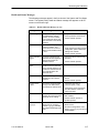
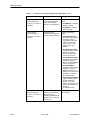
The ATI effective access level (Table 4-1) is the more restrictive of:
Port/Session access level, or
The Access level associated with the Login ID.
For example, if a login ID is created with an Access Level 1 and the Terminal Port
is set for a Port Access Level of 2, the effective access level to the ATI is 2.
Table 4-1. Effective Access Levels
ATI Access to Menu Functions
Effective
Effective
Effective
Access Level 1 Access Level 2 Access Level 3
Status
Full Access
Full Access
Read-Only
Test
Full Access
Full Access
No Access
Configuration
Full Access
Read-Only
Read-Only
Control
Full Access
No Access
No Access
When user access to the ATI is attempted through the Terminal port or a Telnet
session, the ATI response is based on the Login Required option and the
availability of the ATI. Table 4-2 describes how the system responds to various
ATI access conditions.
Table 4-2. ATI Access Conditions (1 of 2)
If access to the ATI
is through the . . .
7112-A2-GB20-20
Then . . .
What to do now?
Terminal port with
Security disabled with
the Login Required
option set to Disable
(See Table A-6)
The Main Menu screen
appears.
Select a menu option to begin your
session.
Terminal port with
Security enabled with
the Login Required
option set to Enable
(See Table A-6)
You are prompted for a
login ID and password.
If Invalid Password appears,
re-enter the password. After three
tries with an invalid password,
contact the system administrator.
The Main Menu screen
appears if the login ID is
not configured yet.
Select a menu option to begin your
session.
March 1998
4-5
Security
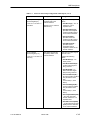
Table 4-2. ATI Access Conditions (2 of 2)
If access to the ATI
is through the . . .
Then . . .
What to do now?
Terminal port and the
ATI is already in use
with a Telnet session
User Interface Already
In Use message appears
with the active user’s IP
address and Login ID.
Try again later.
Telnet session and the
ATI is currently in use
Connection Failed
message appears. The
DSU/CSU allows only
one ATI session.
Try again later.
When the ATI is available, the
message User Interface Idle
appears. Press Enter for the Main
Menu.
Controlling SNMP Access
There are three methods for limiting SNMP access.
Disable the SNMP management option.
Assign SNMP community names and access levels. The DSU/CSU supports
SNMP Version 1, which provides limited security through the use of
community names.
Limit SNMP access through validation of the IP address of each allowed
SNMP manager.
Assigning SNMP Community Names and Access Levels
The DSU/CSU can be managed by an SNMP manager supporting the SNMP
protocol. The community name must be supplied by an external SNMP manager
accessing an object in the MIB.
To define SNMP community names, follow this menu selection sequence:
Main Menu → Configuration → (Load Configuration From) →
SNMP → General SNMP Management
Refer to Table A-8, General SNMP Management Options, to:
4-6
Enable SNMP Management.
Assign the SNMP community names of the SNMP Managers that are allowed
to access the DSU/CSU’s Management Information Base (MIB).
Specify read or read-write access for each SNMP community name.
March 1998
7112-A2-GB20-20
Security
Limiting SNMP Access through the IP Addresses
The DSU/CSU provides an additional level of security through validation of the
IP addresses.
The SNMP Management option must be enabled. To control SNMP access with
IP addresses, follow this menu selection sequence:
Main Menu → Configuration → Load Configuration From →
SNMP→ SNMP NMS Security Options
Refer to Table A-9, SNMP NMS Security Options. The SNMP access can be
limited by:
7112-A2-GB20-20
Enabling NMS IP address validation to perform validation checks on the
IP address of an SNMP management system attempting to access the
DSU/CSU.
Specifying read or read-write access for each NMS authorized to access the
unit.
March 1998
4-7
Security
This page intentionally left blank.
4-8
March 1998
7112-A2-GB20-20
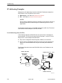
IP Addressing
5
IP Addressing
There are three IP addressing strategies to provide SNMP NMS connectivity.
Local addressing only
Extending subnet for FDL
Unique subnet for the FDL
Review the following information before selecting an IP addressing scheme.
Assign an IP address for the 10BaseT port and FDL management interfaces.
Set the default gateway address. This is a default route for all destinations
not on the LAN. The gateway should be a router on the LAN with routes to
the rest of the network
Each DSU/CSU routing table supports a maximum of 20 routes.
— A subnet route is automatically added for the 10BaseT port
— A Host route is automatically added for the FDL link using RIP
7112-A2-GB20-20
Any legal host address is allowed for a given subnet.
March 1998
5-1
IP Addressing
IP Addressing Examples
Management of IP addressing is based on individual IP addresses assigned to
each interface. The IP interfaces for the unit are:
Ethernet port – See Table A-5, Ethernet Port Options.
FDL – See Table A-2, Network Interface Options.
NOTE:
Do not assign IP addresses without the assistance of the network manager or
individuals responsible for determining the IP addressing scheme for your
organization.
The following examples apply to IP (SNMP) management traffic only. The subnet
mask shown for these examples is 255.255.255.000.
Local Addressing Only (No FDL)
In the following example, the DSU/CSUs do not use the FDL for management
communications. This can be the result of using Fractional T1 service or Frame
Relay Service. In this example both DSU/CSUs:
Only receive management data through the 10BaseT port connection.
Do not route the data between themselves. Routers route the management
data for the connected DSU/CSUs using the user data path between the
routers.
The following illustration shows each DSU/CSU with its own IP address on the
LAN subnet.
Subnet 135.18.5.0
Ethernet Port
IP Address:
135.18.5.2
Subnet 135.18.1.0
7112
DSU/CSU
A
NMS
135.18.1.2
135.18.1.1
Router
T1
Network
135.18.5.1
135.18.4.1
Router
7112
DSU/CSU
B
Ethernet Port
IP Address:
135.18.4.2
Subnet 135.18.4.0
98 -15700-01
5-2
March 1998
7112-A2-GB20-20
IP Addressing
FDL Connection – Extending Subnet for FDL
In this example:
DSU/CSU A is connected to the NMS on LAN A through the 10BaseT port.
DSU/CSU A is connected to DSU/CSU B through the FDL.
DSU/CSU B is addressed through the FDL as if it existed on LAN A.
DSU/CSU A forwards all data to DSU/CSU B using Proxy ARP.
A proprietary RIP is used to learn the IP addresses of the remote FDL
interfaces. It can take up to 5 minutes for the RIP protocol to exchange
addresses once the FDL is active.
Subnet 135.18.5.0
Subnet 140.20.10.0
NMS A
NMS B
135.18.5.2
140.20.10.1
135.18.5.1
Router
Ethernet IP
Address:
135.18.5.3
140.20.10.2
T1
Network
7112
DSU/CSU
A
Router
FDL
FDL IP
Address:
140.20.10.4
FDL IP
Adress:
135.18.5.4
Ethernet IP
Address:
140.20.10.3
7112
DSU/CSU
B
LAN B
LAN A
7112-A2-GB20-20
March 1998
97-15699-01
5-3
IP Addressing
FDL Connection – Unique FDL Subnet
In this example:
DSU/CSU A is connected to the NMS on LAN A through the 10BaseT port.
DSU/CSU A is connected to DSU/CSU B through the FDL.
DSU/CSU A and DSU/CSU B create their own unique Subnet (LAN C).
NOTE:
Interconnected DSU/CSUs automatically pass routing information between
each other using a proprietary protocol. However, a static route to subnet
138.20.18.2 must be set in the routing table of the NMS Host or Router.
Subnet 140.20.10.0
Subnet 135.18.5.0
NMS A
NMS B
135.18.5.2
135.18.5.1
Ethernet IP
Address:
135.18.5.3
7112
DSU/CSU
A
140.20.10.1
Router
140.20.10.2
T1
Network
FDL
FDL IP
Address:
138.20.18.1
Router
FDL IP
Address:
138.20.18.2
7110 or 7112
DSU/CSU
B
LAN A
5-4
LAN C
March 1998
LAN B
97-15698-01
7112-A2-GB20-20
IP Addressing
Assigning IP Addresses and Subnet Masks
After selecting an IP scheme, assign an address to the DSU/CSUs.
If using the . . .
Then assign the . . .
10BaseT port as a management interface
10BaseT port IP address and subnet
mask. Refer to Table A-5, Ethernet Port
Options.
FDL
IP address and subnet mask. Refer to
Table A-2, Network Interface Options.
The DSU/CSU can validate the IP address of an NMS that attempts to access it.
Refer to Table A-9, SNMP NMS Security Options.
7112-A2-GB20-20
March 1998
5-5
IP Addressing
This page intentionally left blank.
5-6
March 1998
7112-A2-GB20-20
Monitoring the DSU/CSU
6
What to Monitor
This chapter presents information on how to access and monitor DSU/CSU status
and performance statistics on the T1 network. You can monitor DSU/CSU
operations by monitoring:
7112-A2-GB20-20
LEDs on the Status screen or the DSU/CSU’s front panel
System and Test Status screens
Highest priority Health and Status message on the last line of all screens
Cross Connect Status screen
Network Interface Status screen
Network Performance Statistics screen
Network Management System via SNMP MIB objects
SNMP traps and other information reported by your NMS via SNMP MIB
objects
March 1998
6-1
Monitoring the DSU/CSU
Table 6-1 shows the available indicators of alarm conditions on the network
interface and the User Data port.
Table 6-1. Alarm Indicator Locations
Status
Screen
Alarm Condition
Network
LED
Loss of Signal (LOS)
Y
SIG
Out of Frame (OOF)
Y
OOF
Alarm Indication Signal (AIS)
Y
ALARM
Excessive Error Rate (EER)
Y
EER
Yellow
Y
ALARM
DSU/CSU LEDs
The DSU/CSU LEDs can be viewed on the Display LEDs Status screen. This ATI
status screen is available locally and remotely.
The 12 LEDs are organized in three groups:
System LEDs display the status of the unit.
Network LEDs provide the status of the network interface.
Port LEDs display the activity on the user data (DTE) port.
To view the LED status screen, follow this menu selection sequence:
Main Menu → Status → Display LEDs
main/status/leds
Device Name:
PARADYNE
Model: 7112
DISPLAY LEDS
SYSTEM
Î
Î
OK
FAIL
TEST
NETWORK
SIG
OOF
ALARM
PORT
EER
TXD
RXD
RTS
CTS
DTR
ÎÎ
ÎÎ
––––––––––––––––––––––––––––––––––––––––––––––––––––––––––––––––––––––––––––––––
ESC for previous menu
MainMenu
Exit
Refresh
When viewed via the ATI, the status display screen is updated approximately
every 5 seconds. Use Refresh to obtain a current status of all LEDs.
6-2
March 1998
7112-A2-GB20-20
Monitoring the DSU/CSU
System LEDs
OK:
ON – DSU/CSU is operational.
OFF – DSU/CSU is performing a power-up self-test, has detected a
system failure, or there is no power.
FAIL:
ON – DSU/CSU has detected a system or device failure, or
is performing a power-up self-test. Refer to
Troubleshooting in Chapter 8.
TEST:
ON – Test in progress. Test can be initiated locally, remotely,
or from the network. Includes power-up self-test.
7112-A2-GB20-20
March 1998
6-3
Monitoring the DSU/CSU
Network LEDs
SIG – Network Signal
ON – A recoverable signal is present on the
network interface.
OFF – The network signal cannot be recovered. A
Loss of Signal condition exists.
OOF – Out of Frame:
ON – An out of frame condition was detected
on the network interface. Refer to
Table 6-2, Health and Status Messages.
Alarm:
ON – DSU/CSU has detected an alarm
condition on the received network
signal. Refer to Troubleshooting in
Chapter 8.
EER – Excessive Error Rate:
ON – The EER threshold has been
exceeded on the network
interface. Refer to Table 6-2,
Health and Status Messages.
6-4
March 1998
7112-A2-GB20-20
Monitoring the DSU/CSU
Port LEDs
TXD – Transmitted Data:
ON
– Receiving a 0 from the DTE.
OFF
– Receiving a 1 from the DTE.
RXD – Received Data:
ON
– Sending a 0 to the DTE.
OFF
– Sending a 1 to the DTE.
RTS – Request to Send:
ON – DTE is activating a control signal to
indicate readiness to transmit data.
CTS – Clear to Send:
ON – DSU/CSU is activating a control
signal to indicate to the DTE that
it can start sending data.
DTR – Data Terminal Ready:
ON – DTE is activating a control signal to
indicate readiness for operation.
7112-A2-GB20-20
March 1998
6-5
Monitoring the DSU/CSU
Status Screen Commands
The status screens appear with the cursor in the function area below the dotted
line. To update the information displayed, select Refresh and press Enter.
The System and Test Status screen provides a Clear command. Select Clear and
press Enter to clear status messages for one-time events.
Statistics screens provide a ClrStats command. Select ClrStats and press Enter
to clear all statistics and refresh the screen. ClrStats is not available for an
Access level of 3.
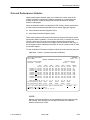
System and Test Status
To view System and Test Status information, follow this menu selection
sequence:
Main Menu → Status → System and Test Status
The System and Test Status screen has three sections:
Health and Status – Displays messages in priority order (highest to lowest).
Refer to Table 6-2, Health and Status Messages.
Self-Test Results – Results of the Diagnostic test run on the device itself.
Refer to Table 6-3, Self-Test Results Messages.
Test Status – Currently active tests. Refer to Table 6-4, Test Status
Messages.
ÎÎÎÎÎÎÎÎÎÎÎÎÎÎÎÎÎÎÎÎÎÎÎÎÎ
ÎÎÎÎÎÎÎÎÎÎÎÎÎÎÎÎÎÎÎÎÎÎÎÎÎ
ÎÎÎÎÎÎÎÎÎÎÎÎÎÎÎÎÎÎÎÎÎÎÎÎÎ
ÎÎÎÎÎÎÎÎÎÎÎÎÎÎÎÎÎÎÎÎÎÎÎÎÎ
ÎÎÎÎÎÎÎÎÎÎÎÎÎÎÎÎÎÎÎÎÎÎÎÎÎ
ÎÎÎÎÎÎÎÎÎÎÎÎÎÎÎÎÎÎÎÎÎÎÎÎÎ
ÎÎÎÎÎÎÎÎÎÎÎÎÎÎÎÎÎÎÎÎÎÎÎÎÎ
ÎÎÎÎÎÎÎÎÎÎÎÎÎÎÎÎÎÎÎÎÎÎÎÎÎ
ÎÎÎÎÎÎÎÎÎÎÎÎÎÎÎÎÎÎÎÎÎÎÎÎÎ
ÎÎÎÎÎÎÎÎÎÎÎÎÎÎÎÎÎÎÎÎÎÎÎÎÎ
ÎÎÎÎÎÎÎÎÎÎÎÎÎÎÎÎÎÎÎÎÎÎÎÎÎ
ÎÎÎÎÎÎÎÎÎÎÎÎÎÎÎÎÎÎÎÎÎÎÎÎÎ
ÎÎÎÎÎÎÎÎÎÎÎÎÎÎÎÎÎÎÎÎÎÎÎÎÎ
ÎÎÎÎÎÎÎÎÎÎÎÎÎÎÎÎÎÎÎÎÎÎÎÎÎ
ÎÎÎÎÎÎÎÎÎÎÎÎÎÎÎÎÎÎÎÎÎÎÎÎÎ
ÎÎÎÎÎÎÎÎÎÎÎÎÎÎÎÎÎÎÎÎÎÎÎÎÎ
main/status/system
Device Name:
PARADYNE
Model: 7112
SYSTEM AND TEST STATUS
HEALTH AND STATUS
SELF-TEST RESULTS
TEST STATUS
–––––––––––––––––––––––––––––––––––––––––––––––––––––––––––––––––––––––––––––––
Loss of Signal
CPU Fail
No Test Active
Out of Frame
Device Fail
Line Loopback Active
Alarm Indication Signal
B8ZS/LOS Fail
Payload Loopback Active
Excessive Error Rate
Network T1 Fail
Repeater Loopback Active
Yellow Alarm
Alarm Fail
Data Channel Loopback Active
Primary Clock Failed
Memory Fail
Data Terminal Loopback Active
FDL Link Down
DSU/CSU Port Fail
Ptrn Test Active, Network
Device Fail yyyyyyyy
Failure xxxxxxxx
Mon Ptrn Test Active, Network
Ptrn Test Active, Port
User Data Port Down
Passed
Ethernet Port Down
Mon Ptrn Test Active, Port
System Operational
Lamp Test Active
–––––––––––––––––––––––––––––––––––––––––––––––––––––––––––––––––––––––––––––––
ESC for previous menu
MainMenu
Exit
Refresh
Clear
6-6
March 1998
7112-A2-GB20-20
Monitoring the DSU/CSU
Health and Status Messages
The following messages appear in the first column of the System and Test Status
screen. The highest priority Health and Status message also appears on all ATI
screens on the bottom right.
Table 6-2. Health and Status Messages (1 of 2)
Message
What Message Indicates
What To Do
Loss Of Signal
No signal is being received.
Local DSU/CSU network
problem. An LOS condition
(175 consecutive zeros) has
been detected on the network
interface.
1. Verify that the network cable is
securely attached at both ends.
Out of Frame
DSU/CSU is detecting an out 1. Wait for the condition to clear.
of frame condition. This
2. Verify that the line framing format
occurs when two out of four
configuration option matches the
frame synchronization bits are
setting of the network.
in error.
3. Contact network provider.
Alarm Indication
Signal
An Alarm Indication Signal
(unframed all ones signal) is
being received from the
network interface.
1. Check the status of the far-end
device(s).
Excessive Error
Rate
An Excessive Error Rate
condition has been detected
on the network interface. The
condition is cleared when the
error rate falls below the
threshold value.
1. Contact network provider.
Yellow Alarm
A Yellow Alarm signal is being 1. Check the status of the far-end
device.
received from the network
interface.
2. Contact network provider.
Primary Clock
Failed
The primary clock has failed. 1. Check the clock source
connector (DTE or Net).
Timing for the DSU/CSU is
provided by the internal clock.
2. If the primary clock was derived
from the network, contact the
network provider.
FDL Link Down
The FDL communication
between the local and remote
DSU/CSU is not working.
Device Fail
yyyyyyyy
7112-A2-GB20-20
2. Contact network provider.
2. Contact network provider.
1. Verify that the remote unit has
FDL enabled.
2. Contact network provider if
problem persists.
An internal error has been
1. Select the Clear function from the
Status screen.
detected by the operating
software. yyyyyyyy indicates
the 8-digit hexadecimal failure 2. Provide the 8-digit failure code
shown ( yyyyyyyy ) to your service
code.
representative.
March 1998
6-7
Monitoring the DSU/CSU
Table 6-2. Health and Status Messages (2 of 2)
Message
What Message Indicates
What To Do
User Data Port
Down
The DTE is not ready to
transmit or receive data.
1. Check on the DTE status. Verify
that the DTE is powered up and
asserting DTR and RTS.
2. Disable send all 1’s on data port
not ready.
Ethernet Link
Down
System
Operational
The DSU/CSU detects no
electrical activity on the
10BaseT port.
1. Verify that the Ethernet cable is
securely attached at both ends.
The unit is functioning
properly and there are no
status messages to display.
No action required.
2. Contact your LAN support
technician if problem persists.
Self-Test Results
The results of the last power-up or reset self-test appear in the middle column of
the System and Test Status screen.
Table 6-3. Self-Test Results Messages
6-8
Message
What Message Indicates
What To Do
CPU Fail
The CPU failed internal testing.
1. Reset the unit and try again.
Device Fail
One or more of the DSU/CSU’s
integrated circuit chips has failed
device-level testing.
2. Select the Clear function on
the Status screen.
3. Call your service
assistance
representative for assistance.
B8ZS/LOS
Fail
The DSU/CSU failed to transmit all
ones or to detect a Loss of Signal.
Network T1
Fail
The DSU/CSU failed to internally
loop data on the network T1 circuit.
Alarm Fail
The DSU/CSU failed to transmit AIS
or to detect a Yellow alarm.
Memory Fail
The DSU/CSU failed memory
verification.
DSU/CSU
Port Fail
The Data Port failed self-test.
Failure
xxxxxxxx
An internal failure occurred.
(xxxxxxxx represents an eight-digit
hexadecimal failure code for use by
service personnel.)
Record the failure code and
contact your service
representative.
Passed
No problems were found during
power-up.
No action needed; no problems
were found during power-up or
reset.
March 1998
7112-A2-GB20-20
Monitoring the DSU/CSU
Test Status Messages
The Test Status messages in the following table appear in the right column of the
System and Test Status screen.
Table 6-4. Test Status Messages
7112-A2-GB20-20
Test Status Message
Meaning
No Test Active
No tests are currently running.
Line Loopback Active
The network Line Loopback test is active.
Payload Loopback
Active
The network Payload Loopback test is active.
Repeater Loopback
Active
The network Repeater Loopback test is active.
Data Channel
Loopback Active
The Data Channel Loopback test is active for the data port.
Data Terminal
Loopback Active
The Data Terminal Loopback test is active for the data port.
QRSS Test Active,
Network
The QRSS test pattern is being sent over the network interface.
1-in-8 Test Active,
Network
The 1-in-8 test pattern is being sent over the network interface.
Mon QRSS Test
Active, Network
DSU/CSU is monitoring a QRSS test pattern over the network
interface.
QRSS Test Active,
Port
The QRSS test pattern is being sent on the port interface.
511 Test Active, Port
The 511 test pattern is being sent on the port interface.
Mon QRSS Test
Active, Port
DSU/CSU is monitoring a QRSS test pattern on the port
interface.
Mon 511 Test Active,
Port
DSU/CSU is monitoring a 511 test pattern on the port interface.
Lamp Test Active
The Lamp Test is active, causing the LEDs on the front panel to
light.
March 1998
6-9
Monitoring the DSU/CSU
Cross Connect Status
Use the Cross Connect Status screen to display the network interface time slots
assigned to the data port. These assignments are made using the Cross Connect
configuration option.
Use the following menu sequence to display network channel information.
Main Menu → Status → Cross Connect Status
The Cross Connect Status screen displays 24 two-field entries in three rows.
Together, each two-field entry defines the assignment for one network interface
time slot. The top field represents the time slot of the network interface. The
bottom field shows whether or not the time slot is assigned to the data port.
main/status/cross_connect
Device Name:
PARADYNE
Model: 7112
CROSS CONNECT STATUS
Î
Î
N01
P
N02
P
N03
P
N04
P
N05
P
N06
P
N07
N08
N09
N10
N11
N12
N13
N14
N15
N16
N17
N18
N19
N20
N21
N22
N23
N24
ÎÎ
ÎÎ
––––––––––––––––––––––––––––––––––––––––––––––––––––––––––––––––––––––––––––––––
ESC for previous menu
MainMenu
Exit
The following information is available for viewing.
6-10
The Network Time Slot Fields (top) . . .
Indicate the . . .
N01 to N24
Network Interface time slot (01 to 24).
The Cross Connect Status Field
(bottom) . . .
Indicates the time slot is . . .
blank
Unassigned.
P
Assigned to the data port.
March 1998
7112-A2-GB20-20
Monitoring the DSU/CSU
Network Performance Statistics
Network performance statistics allow you to monitor the current status of the
network operations. Performance statistics can assist you in determining the
duration of specific conditions and provide a historical context for problem
detection and analysis.
When the network interface is configured for ESF framing, network performance
is continuously monitored and maintained in two sets of aggregate registers:
Carrier Network Interface Registers (Telco)
User Network Interface Registers (User)
These status registers collect performance data for the previous 24-hour period.
Performance data is updated in 15-minute intervals. After 15 minutes, the current
interval is rolled over into a set of accumulator registers that represent the
previous 96 15-minute intervals for the register. An interval total of how many of
the 96 registers contain valid data is also kept, as well as a 24-hour total for each
accumulator register.
To view the Network Performance Statistics, follow this menu selection sequence:
Main Menu → Status → Network Performance Statistics
ÎÎÎÎÎÎÎÎÎÎÎÎÎÎÎÎÎÎÎÎÎÎÎÎÎ
ÎÎÎÎÎÎÎÎÎÎÎÎÎÎÎÎÎÎÎÎÎÎÎÎÎ
ÎÎÎÎÎÎÎÎÎÎÎÎÎÎÎÎÎÎÎÎÎÎÎÎÎ
ÎÎÎÎÎÎÎÎÎÎÎÎÎÎÎÎÎÎÎÎÎÎÎÎÎ
ÎÎÎÎÎÎÎÎÎÎÎÎÎÎÎÎÎÎÎÎÎÎÎÎÎ
ÎÎÎÎÎÎÎÎÎÎÎÎÎÎÎÎÎÎÎÎÎÎÎÎÎ
ÎÎÎÎÎÎÎÎÎÎÎÎÎÎÎÎÎÎÎÎÎÎÎÎÎ
ÎÎÎÎÎÎÎÎÎÎÎÎÎÎÎÎÎÎÎÎÎÎÎÎÎ
ÎÎÎÎÎÎÎÎÎÎÎÎÎÎÎÎÎÎÎÎÎÎÎÎÎ
ÎÎÎÎÎÎÎÎÎÎÎÎÎÎÎÎÎÎÎÎÎÎÎÎÎ
ÎÎÎÎÎÎÎÎÎÎÎÎÎÎÎÎÎÎÎÎÎÎÎÎÎ
ÎÎÎÎÎÎÎÎÎÎÎÎÎÎÎÎÎÎÎÎÎÎÎÎÎ
ÎÎÎÎÎÎÎÎÎÎÎÎÎÎÎÎÎÎÎÎÎÎÎÎÎ
ÎÎÎÎÎÎÎÎÎÎÎÎÎÎÎÎÎÎÎÎÎÎÎÎÎ
ÎÎÎÎÎÎÎÎÎÎÎÎÎÎÎÎÎÎÎÎÎÎÎÎÎ
ÎÎÎÎÎÎÎÎÎÎÎÎÎÎÎÎÎÎÎÎÎÎÎÎÎ
main/status/performance
Device Name:
PARADYNE
Model: 7112
NETWORK PERFORMANCE STATISTICS
Current Interval Timer
Telco=438
User=437
Current Int:
Interval 01:
Interval 02:
Interval 03:
Interval 04:
Interval 05:
Interval 06:
Interval 07:
–––ES––
Tel Usr
000 000
000 000
000 000
000 000
000 000
000 000
000 000
000 000
ESF Error Events
Telco=0
User=0
––UAS––
Tel Usr
000 000
000 000
000 000
000 000
000 000
000 000
000 000
000 000
––SES––
Tel Usr
000 000
000 000
000 000
000 000
000 000
000 000
000 000
000 000
––BES––
Tel Usr
000 000
000 000
000 000
000 000
000 000
000 000
000 000
000 000
––CSS–– –LOFC–– –Status–
Tel Usr Tel Usr
(User)
000 000 000 000 YL
000 000 000 000 none
000 000 000 000 none
000 000 000 000 none
000 000 000 000 none
000 000 000 000 none
000 000 000 000 none
000 000 000 000 none
Worst Interval:24 24 14 14
14
14
09 09
18 16
44 44
Tel Tot(valid 96):00001 00000
00001
00000
00000
00000
Usr Tot(valid 96):00000 00000
00000
00000
00000
00000
–––––––––––––––––––––––––––––––––––––––––––––––––––––––––––––––––––––––––––––––
Ctrl–a to access these functions, ESC for previous menu
MainMenu
Exit
Refresh PgDn PgUp ClrStats
Select: 01, 02, 03, 04, 05, 06, 07, 08, 09...
NOTE:
Network performance statistics are only available for those interfaces using
ESF framing. Verify that the Line Framing Format field on the Network
Interface screen is set to ESF.
7112-A2-GB20-20
March 1998
6-11
Monitoring the DSU/CSU
You can reset the user performance registers via the ClrStats selection on the
Performance Statistics screen.
NOTE:
ClrStats only resets the user events. Telco events are cleared during a
power-on reset.
There are four sections to the Network Performance Statistics screen:
Summary Information
Interval Table
Worst Interval
24-Hour Totals
Summary Information
Summary information provides the following information:
Current Interval Timer – displays the number of seconds that have elapsed
in the current 15-minute interval.
ESF Error Events – displays the number of ESF frames with either a CRC
error or an OOF event.
The ESF Error Event statistic is not reset every 15 minutes. If the counter
reaches 65,535, it remains at this value until reset.
The Telco counter for ESF Error Events can only be cleared by a reset
command from the network or a reset of the device itself.
The User counter for ESF Error Events can only be reset by selecting the
ClrStats option or by resetting the device.
Interval Table
Network performance statistics are kept for each 15-minute interval over the past
24-hour period. There are six types of statistics recorded:
6-12
Errored Seconds (ES) – The number of errored seconds for the current
interval. An errored second is any second with one or more ESF error events.
The maximum is 900 seconds.
Unavailable Seconds (UAS) – The number of unavailable seconds for the
current interval. An unavailable second is any one second interval when
service is unavailable. (Detection occurs with 10 consecutive unavailable
seconds.) The maximum is 900 seconds.
Severely Errored Seconds (SES) – The number of severely errored
seconds for the current interval. A severely errored second is any second
with 320 or more CRC errors, or any second with one or more OOF events.
The maximum is 900 seconds.
March 1998
7112-A2-GB20-20
Monitoring the DSU/CSU
Bursty Errored Seconds (BES) –The number of bursty errored seconds for
the current interval. A bursty errored second is any second with more than
one, but less than 320, CRC errors. The maximum is 900 seconds.
Controlled Slip Seconds (CSS) – The number of controlled slip seconds for
the current interval.
Loss of Frame Count (LOFC) – The loss of frame count for the current
interval. This is a count of the number of times that an LOF is declared. The
maximum count is 255.
A Telco set and a user set are kept for each of the above statistics. The user set
is a copy of the Telco set, but the user set can be cleared.
In addition to the statistics kept for the network interface, the system maintains a
Status register for each interval (far-right column). The Status register shows
whether or not the following events have occurred at least once within the
15-minute interval:
Y – Yellow Alarm
L – Loss of Signal
E – Excessive Error Rate
F – Frame Synchronization Bit Error
V – Line Code Violation
none
Every 15 minutes, the current interval’s data is rolled over into a set of
accumulator registers that represent the previous 96 15-minute intervals for the
register. All counts show the number of occurrences since the last reset of the
counters.
When you enter the Network Performance Statistics screen, the current interval
and seven most recent intervals are displayed. To display other intervals:
Use the PgUp and PgDn selections. Intervals display as a series of
7 consecutive periods (recent to old).
Tab to one of the rows in the interval table that has an underlined interval
number (intervals 1, 4, and 7 when first displayed). Type the number of the
interval you want to display at any of these three underlined locations.
Intervals are numbered from 1 (most recent) to 96 (oldest). For example:
— Enter 10 on the top line to display intervals 10 through 17.
— Enter 10 on the middle line to display intervals 7 through 13.
— Enter 10 on the bottom line to display intervals 4 through 10.
Worst Interval
To assist you in selecting trouble spots, a Worst Interval is also displayed. The
Worst Interval is the 15-minute period that contains the largest number of
seconds for either ES, UAS, SES, BES, or CSS, or the greatest Loss of Frame
Count (LOFC). If more than one interval contains the same worst value, then the
oldest interval is displayed.
7112-A2-GB20-20
March 1998
6-13
Monitoring the DSU/CSU
24-Hour Totals
The last two lines on the screen (above the dotted line) display the totals for each
statistic over the last 24 hours, along with the number of valid intervals included in
the total (up to 96).
Ethernet Port Status
To view the Ethernet (10BaseT) Port Status, follow this menu selection sequence:
Main Menu → Status → Ethernet Port Status
ÎÎÎÎÎÎÎÎÎÎÎÎÎÎÎÎÎÎÎÎÎÎÎÎÎ
ÎÎÎÎÎÎÎÎÎÎÎÎÎÎÎÎÎÎÎÎÎÎÎÎÎ
ÎÎÎÎÎÎÎÎÎÎÎÎÎÎÎÎÎÎÎÎÎÎÎÎÎ
ÎÎÎÎÎÎÎÎÎÎÎÎÎÎÎÎÎÎÎÎÎÎÎÎÎ
ÎÎÎÎÎÎÎÎÎÎÎÎÎÎÎÎÎÎÎÎÎÎÎÎÎ
ÎÎÎÎÎÎÎÎÎÎÎÎÎÎÎÎÎÎÎÎÎÎÎÎÎ
ÎÎÎÎÎÎÎÎÎÎÎÎÎÎÎÎÎÎÎÎÎÎÎÎÎ
ÎÎÎÎÎÎÎÎÎÎÎÎÎÎÎÎÎÎÎÎÎÎÎÎÎ
ÎÎÎÎÎÎÎÎÎÎÎÎÎÎÎÎÎÎÎÎÎÎÎÎÎ
ÎÎÎÎÎÎÎÎÎÎÎÎÎÎÎÎÎÎÎÎÎÎÎÎÎ
ÎÎÎÎÎÎÎÎÎÎÎÎÎÎÎÎÎÎÎÎÎÎÎÎÎ
ÎÎÎÎÎÎÎÎÎÎÎÎÎÎÎÎÎÎÎÎÎÎÎÎÎ
ÎÎÎÎÎÎÎÎÎÎÎÎÎÎÎÎÎÎÎÎÎÎÎÎÎ
ÎÎÎÎÎÎÎÎÎÎÎÎÎÎÎÎÎÎÎÎÎÎÎÎÎ
ÎÎÎÎÎÎÎÎÎÎÎÎÎÎÎÎÎÎÎÎÎÎÎÎÎ
ÎÎÎÎÎÎÎÎÎÎÎÎÎÎÎÎÎÎÎÎÎÎÎÎÎ
main/status/ethernet
Device Name:
PARADYNE
Model: 7112
ETHERNET PORT STATUS
Port Use:
IP Address:
Subnet Mask:
Default Gateway Address:
Ethernet MAC Address:
Version 2
000.000.000.000
000.000.000.000
000.000.000.000
00:00:00:00:00:00
Frames Transmitted:
Frames Received:
Errored Frames:
Excessive Collisions:
Carrier Sense Errors:
Deferred Transmissions:
0000000000
0000000000
0000000000
0000000000
0000000000
0000000000
–––––––––––––––––––––––––––––––––––––––––––––––––––––––––––––––––––––––––––––––
Exit
ESC for previous menu
MainMenu
ClrStats
Refresh
Table 6-5 describes the fields on the Ethernet Port Status screen.
Table 6-5. Ethernet Port Status Screen Contents (1 of 2)
6-14
Label
What the Field Indicates
Port Use
The port is enabled if 802.3 or Version 2 is displayed. The
port is disabled if Disable is displayed.
IP Address
The IP address of the port.
Subnet Mask
The subnet mask to be used with the IP address.
Default Gateway Address
The gateway to be used for packets that do not have a
route.
Ethernet MAC Address
The physical address of the port.
Frames Transmitted
The number of frames transmitted.
Frames Received
The number of frames received.
March 1998
7112-A2-GB20-20
Monitoring the DSU/CSU
Table 6-5. Ethernet Port Status Screen Contents (2 of 2)
Label
What the Field Indicates
Errored Frames
The number of frames in error. This is the sum of frames
with alignment errors, FCS (Frame Check Sequence) errors,
and framing errors.
Excessive Collisions
The number of frames for which transmission failed due to
excessive collisions.
Carrier Sense Errors
The number of times the carrier sense condition was lost or
never asserted.
Deferred Transmissions
The number of frames for which the first transmission
attempt is delayed because the medium is busy.
All counts show the number of occurrences since the last reset of the counters.
Management Protocol Statistics
To view the Management Protocol Statistics, follow this menu selection
sequence:
Main Menu → Status → Management Protocol Statistics
ÎÎÎÎÎÎÎÎÎÎÎÎÎÎÎÎÎÎÎÎÎÎÎÎÎ
ÎÎÎÎÎÎÎÎÎÎÎÎÎÎÎÎÎÎÎÎÎÎÎÎÎ
ÎÎÎÎÎÎÎÎÎÎÎÎÎÎÎÎÎÎÎÎÎÎÎÎÎ
ÎÎÎÎÎÎÎÎÎÎÎÎÎÎÎÎÎÎÎÎÎÎÎÎÎ
ÎÎÎÎÎÎÎÎÎÎÎÎÎÎÎÎÎÎÎÎÎÎÎÎÎ
ÎÎÎÎÎÎÎÎÎÎÎÎÎÎÎÎÎÎÎÎÎÎÎÎÎ
ÎÎÎÎÎÎÎÎÎÎÎÎÎÎÎÎÎÎÎÎÎÎÎÎÎ
ÎÎÎÎÎÎÎÎÎÎÎÎÎÎÎÎÎÎÎÎÎÎÎÎÎ
ÎÎÎÎÎÎÎÎÎÎÎÎÎÎÎÎÎÎÎÎÎÎÎÎÎ
ÎÎÎÎÎÎÎÎÎÎÎÎÎÎÎÎÎÎÎÎÎÎÎÎÎ
ÎÎÎÎÎÎÎÎÎÎÎÎÎÎÎÎÎÎÎÎÎÎÎÎÎ
ÎÎÎÎÎÎÎÎÎÎÎÎÎÎÎÎÎÎÎÎÎÎÎÎÎ
ÎÎÎÎÎÎÎÎÎÎÎÎÎÎÎÎÎÎÎÎÎÎÎÎÎ
ÎÎÎÎÎÎÎÎÎÎÎÎÎÎÎÎÎÎÎÎÎÎÎÎÎ
ÎÎÎÎÎÎÎÎÎÎÎÎÎÎÎÎÎÎÎÎÎÎÎÎÎ
ÎÎÎÎÎÎÎÎÎÎÎÎÎÎÎÎÎÎÎÎÎÎÎÎÎ
main/status/management
Device Name: Node A
PARADYNE
Model: 7112
MANAGEMENT PROTOCOL STATISTICS
TCP
IP
Datagrams Transmitted:
Datagrams Received:
Format Errors:
Invalid Address:
Unknown Protocol:
Dropped Due To No Route:
0
0
0
0
0
0
UDP
0
0
0
–
–
–
0
0
0
0
–
–
––––––––––––––––––––––––––––––––––––––––––––––––––––––––––––––––––––––––––––––––
Exit
ESC for previous menu
MainMenu
Refresh
ClrStats
7112-A2-GB20-20
March 1998
6-15
Monitoring the DSU/CSU
Table 6-6 describes the fields on the Management Protocol Statistics screen.
Table 6-6. Management Protocol Statistics Screen Contents
Label
What the Field Indicates
Datagrams Transmitted
The number of datagrams successfully transmitted at each
protocol layer.
Datagrams Received
The number of datagrams successfully received at each
protocol layer.
Format Errors
The number of protocol packets that contained errors.
Invalid Address
The number of protocol packets that contained invalid
addresses.
Unknown Protocol
The number of datagrams that were lost due to unknown
protocols.
Dropped Due To No
Route
The number of datagrams that were lost due to no route.
All counts show the number of occurrences since the last reset of the counters.
6-16
March 1998
7112-A2-GB20-20
Testing
7
Detecting Problems
The DSU/CSU can detect and report problem conditions and perform diagnostic
tests. The DSU offers a number of indicators to alert you to possible problems:
LEDs – Refer to DSU/CSU LEDs in Chapter 6, Monitoring the DSU/CSU.
SNMP Traps – For information on traps, refer to Configuring SNMP Traps in
Chapter 8, Messages and Troubleshooting.
Health and status messages and network performance statistics. Refer to
Chapter 6, Monitoring the DSU/CSU.
Alarm Condition Indications.
The following table shows the available indicators of alarm conditions on the
network interface and the User Data port.
SNMP
Trap
Alarm Condition
Specific
LED
Loss of Signal (LOS)
Y1
Y
Y
Out of Frame (OOF)
Y1
Y
Y
Alarm Indication Signal (AIS)
Y1
Y
N
Excessive Error Rate (EER)
Y1
Y
N
Yellow
Y1
Y
Y
FDL Link Down
Y1
Y
N
User Data Port Down
Y1
Y
Y
1
7112-A2-GB20-20
ATI
Status
Screen
Link Up/Link Down Trap
March 1998
7-1
Testing
Accessing the Test Menu
From the Test menu, you can run network tests, data port tests, and a lamp test
for the front panel LEDs.
The Test menu is limited to users with an access level of 1 or 2 (Refer to
Chapter 4, Security). To access the Test menu, follow this menu selection
sequence:
Main Menu → Test
ÎÎÎÎÎÎÎÎÎÎÎÎÎÎÎÎÎÎÎÎÎÎÎÎÎ
ÎÎÎÎÎÎÎÎÎÎÎÎÎÎÎÎÎÎÎÎÎÎÎÎÎ
ÎÎÎÎÎÎÎÎÎÎÎÎÎÎÎÎÎÎÎÎÎÎÎÎÎ
ÎÎÎÎÎÎÎÎÎÎÎÎÎÎÎÎÎÎÎÎÎÎÎÎÎ
ÎÎÎÎÎÎÎÎÎÎÎÎÎÎÎÎÎÎÎÎÎÎÎÎÎ
ÎÎÎÎÎÎÎÎÎÎÎÎÎÎÎÎÎÎÎÎÎÎÎÎÎ
ÎÎÎÎÎÎÎÎÎÎÎÎÎÎÎÎÎÎÎÎÎÎÎÎÎ
ÎÎÎÎÎÎÎÎÎÎÎÎÎÎÎÎÎÎÎÎÎÎÎÎÎ
ÎÎÎÎÎÎÎÎÎÎÎÎÎÎÎÎÎÎÎÎÎÎÎÎÎ
ÎÎÎÎÎÎÎÎÎÎÎÎÎÎÎÎÎÎÎÎÎÎÎÎÎ
ÎÎÎÎÎÎÎÎÎÎÎÎÎÎÎÎÎÎÎÎÎÎÎÎÎ
ÎÎÎÎÎÎÎÎÎÎÎÎÎÎÎÎÎÎÎÎÎÎÎÎÎ
ÎÎÎÎÎÎÎÎÎÎÎÎÎÎÎÎÎÎÎÎÎÎÎÎÎ
ÎÎÎÎÎÎÎÎÎÎÎÎÎÎÎÎÎÎÎÎÎÎÎÎÎ
ÎÎÎÎÎÎÎÎÎÎÎÎÎÎÎÎÎÎÎÎÎÎÎÎÎ
main/test
Device Name:
PARADYNE
Model: 7112
TEST
Network Tests
Data Port Tests
Lamp Test
Abort Tests
––––––––––––––––––––––––––––––––––––––––––––––––––––––––––––––––––––––––––––––––
Ctrl-a to access these functions ESC for previous menu
MainMenu
Exit
7-2
March 1998
7112-A2-GB20-20
Testing
Running Network Tests
Network tests require the participation of your network service provider. To
access the Network Tests screen, follow this menu selection sequence:
Main Menu → Test → Network Tests
ÎÎÎÎÎÎÎÎÎÎÎÎÎÎÎÎÎÎÎÎÎÎÎÎÎ
ÎÎÎÎÎÎÎÎÎÎÎÎÎÎÎÎÎÎÎÎÎÎÎÎÎ
ÎÎÎÎÎÎÎÎÎÎÎÎÎÎÎÎÎÎÎÎÎÎÎÎÎ
ÎÎÎÎÎÎÎÎÎÎÎÎÎÎÎÎÎÎÎÎÎÎÎÎÎ
ÎÎÎÎÎÎÎÎÎÎÎÎÎÎÎÎÎÎÎÎÎÎÎÎÎ
ÎÎÎÎÎÎÎÎÎÎÎÎÎÎÎÎÎÎÎÎÎÎÎÎÎ
ÎÎÎÎÎÎÎÎÎÎÎÎÎÎÎÎÎÎÎÎÎÎÎÎÎ
ÎÎÎÎÎÎÎÎÎÎÎÎÎÎÎÎÎÎÎÎÎÎÎÎÎ
ÎÎÎÎÎÎÎÎÎÎÎÎÎÎÎÎÎÎÎÎÎÎÎÎÎ
ÎÎÎÎÎÎÎÎÎÎÎÎÎÎÎÎÎÎÎÎÎÎÎÎÎ
ÎÎÎÎÎÎÎÎÎÎÎÎÎÎÎÎÎÎÎÎÎÎÎÎÎ
ÎÎÎÎÎÎÎÎÎÎÎÎÎÎÎÎÎÎÎÎÎÎÎÎÎ
ÎÎÎÎÎÎÎÎÎÎÎÎÎÎÎÎÎÎÎÎÎÎÎÎÎ
ÎÎÎÎÎÎÎÎÎÎÎÎÎÎÎÎÎÎÎÎÎÎÎÎÎ
ÎÎÎÎÎÎÎÎÎÎÎÎÎÎÎÎÎÎÎÎÎÎÎÎÎ
ÎÎÎÎÎÎÎÎÎÎÎÎÎÎÎÎÎÎÎÎÎÎÎÎÎ
main/test/network
Device Name:
PARADYNE
Model: 7112
NETWORK TESTS
Test
Command
Status
Result
Local Loopbacks
Line Loopback:
Payload Loopback:
Repeater Loopback:
Start
Start
Start
Inactive
Inactive
Inactive
0:00:00
0:00:00
0:00:00
Remote Loopbacks
Send Line Loopback: Up
Send
Inactive
0:00:00
Pattern Tests
Send:
QRSS
Monitor:
QRSS
Start
Start
Active
Active
0:00:00
99:08:48 – Errors 99999+
––––––––––––––––––––––––––––––––––––––––––––––––––––––––––––––––––––––––––––––––
Ctrl-a to access these functions, ESC for previous menu
MainMenu
Exit
Use the Command column to start or stop a test by pressing Enter. The Result
column displays the test duration since the last device reset. When the Monitor
QRSS test is active, ResetMon is available to reset the error counter to zero.
Selecting the Stop command on the Network Test screen or Abort Tests from the
Test menu will not disrupt a network-initiated loopback.
7112-A2-GB20-20
March 1998
7-3
Testing
Line Loopback
Line Loopback (LLB) loops the received signal on the network interface back to
the network without change.
" Procedure
To run a Line loopback:
1. Position the cursor at the Start command next to Line Loopback on the
Network Tests screen and press Enter.
2. The Start command is changed to Stop. If you want to manually stop the test,
verify that the cursor is positioned at the Stop command and press Enter.
DSU
CSU
LLB Network
Interface
ALL 1s
DTE
496-15075
Line Loopback cannot be started when any of the following tests are already
active:
H
Payload Loopback
H
Data Channel Loopback
H
Send Pattern test on the network interface.
Payload Loopback
Payload Loopback (PLB) loops the received signal on the network interface back
to the network. Framing CRCs and BPVs are corrected.
" Procedure
To run a Payload loopback:
1. Position the cursor on the Start command next to Payload Loopback on the
Network Tests screen and press Enter.
The Start command is changed to Stop.
7-4
March 1998
7112-A2-GB20-20
Testing
2. To manually stop the test, verify that the cursor is positioned at the Stop
command and press Enter.
DSU
CSU
PLB Network
Interface
ALL 1s
DTE
496-15076
Payload Loopback cannot be started when any other loopback or Send Pattern
test is already active on the network interface.
Repeater Loopback
Repeater Loopback (RLB) loops the signal being sent from the data port back to
the data port. Framing CRCs and BPVs are corrected.
" Procedure
To run a Repeater loopback:
1. Position the cursor at the Start command next to Repeater Loopback on the
Network Tests screen and press Enter.
2. To manually stop the test, verify that the cursor is positioned at the Stop
command and press Enter.
DSU
CSU
RLB
Network
Interface
ALL 1s
496-15077
DTE
Repeater Loopback cannot be started when any of the following tests are already
active:
7112-A2-GB20-20
H
Data Terminal Loopback
H
Data Channel Loopback
H
Payload Loopback.
March 1998
7-5
Testing
Remote Send Line Loopback
Remote Send Line Loopback sends the line loopback up or down code on the
network interface for 10 seconds.
Procedure
To run a Send Remote Line loopback:
1. Position the cursor at the Up or Down selection next to Send Line Loopback
on the Network Tests screen.
2. Press the space bar to select either Up or Down.
3. Position the cursor at the Send command next to Up or Down selection and
press Enter.
The Send command is changed to Sending. The loopback will stop
automatically after 10 seconds. You cannot stop the Remote Send Line
Loopback test manually.
Remote Send Line Loopback cannot be started when any other loopback or a
Send Pattern test is already active on the network interface.
Test Patterns for the Network
The Send test sends a QRSS or 1-in-8 test pattern over the network interface.
The Monitor test monitors the QRSS test pattern over the network interface.
Procedure
To run a Send pattern test:
1. Position the cursor at the QRSS or 1-in-8 selection next to Send on the
Network Tests screen.
2. Press the space bar to select the desired test pattern (QRSS or 1-in-8).
3. Position the cursor at the Start command next to the selected pattern and
press Enter.
The Start command is changed to Stop.
4. To manually stop the test, verify that the cursor is positioned at the Stop
command and press Enter.
7-6
March 1998
7112-A2-GB20-20
Testing
Procedure
To run a Monitor QRSS test:
1. Position the cursor at the Start command next to Monitor QRSS on the
Network Tests screen.
2. If desired, use Ctrl-a to switch to the screen function key area and use the
virtual function key r or R (ResetMon) to clear the error counter to zero. Press
Ctrl-a to return the cursor to the Start command and press Enter.
The Start command is changed to Stop.
3. To manually stop the test, verify that the cursor is positioned at the Stop
command and press Enter.
The Send and Monitor Pattern tests cannot be started when any loopback is
already active on the network interface.
Running Data Port Tests
To access the Data Port Tests screen, follow this menu selection sequence:
Main Menu → Test → Data Port Tests
ÎÎÎÎÎÎÎÎÎÎÎÎÎÎÎÎÎÎÎÎÎÎÎÎÎ
ÎÎÎÎÎÎÎÎÎÎÎÎÎÎÎÎÎÎÎÎÎÎÎÎÎ
ÎÎÎÎÎÎÎÎÎÎÎÎÎÎÎÎÎÎÎÎÎÎÎÎÎ
ÎÎÎÎÎÎÎÎÎÎÎÎÎÎÎÎÎÎÎÎÎÎÎÎÎ
ÎÎÎÎÎÎÎÎÎÎÎÎÎÎÎÎÎÎÎÎÎÎÎÎÎ
ÎÎÎÎÎÎÎÎÎÎÎÎÎÎÎÎÎÎÎÎÎÎÎÎÎ
ÎÎÎÎÎÎÎÎÎÎÎÎÎÎÎÎÎÎÎÎÎÎÎÎÎ
ÎÎÎÎÎÎÎÎÎÎÎÎÎÎÎÎÎÎÎÎÎÎÎÎÎ
ÎÎÎÎÎÎÎÎÎÎÎÎÎÎÎÎÎÎÎÎÎÎÎÎÎ
ÎÎÎÎÎÎÎÎÎÎÎÎÎÎÎÎÎÎÎÎÎÎÎÎÎ
ÎÎÎÎÎÎÎÎÎÎÎÎÎÎÎÎÎÎÎÎÎÎÎÎÎ
ÎÎÎÎÎÎÎÎÎÎÎÎÎÎÎÎÎÎÎÎÎÎÎÎÎ
ÎÎÎÎÎÎÎÎÎÎÎÎÎÎÎÎÎÎÎÎÎÎÎÎÎ
ÎÎÎÎÎÎÎÎÎÎÎÎÎÎÎÎÎÎÎÎÎÎÎÎÎ
ÎÎÎÎÎÎÎÎÎÎÎÎÎÎÎÎÎÎÎÎÎÎÎÎÎ
ÎÎÎÎÎÎÎÎÎÎÎÎÎÎÎÎÎÎÎÎÎÎÎÎÎ
main/test/data
Device Name:
PARADYNE
Model: 7112
DATA PORT TESTS
Test
Command
Status
Result
Local Loopbacks
Data Terminal Loopback:
Data Channel Loopback:
Start
Start
Inactive
Inactive
0:00:00
0:00:00
Remote Loopbacks
Send V.54 Loopback: Up
Send FT1 Loopback: Down
Send
Send
Inactive
Inactive
0:00:00
0:00:00
Pattern Tests
Send:
QRSS
Monitor:
QRSS
Start
Stop
Inactive
Active
0:00:00
99:08:48 – Errors 99999+
––––––––––––––––––––––––––––––––––––––––––––––––––––––––––––––––––––––––––––––––
Ctrl-a to access these functions, ESC for previous menu
MainMenu
Exit
ResetMon
7112-A2-GB20-20
March 1998
7-7
Testing
Data Terminal Loopback
Data Terminal Loopback (DTLB) loops the user data back to the DTE. This
loopback is located as closely as possible to the User Data Port (DTE) interface.
Procedure
To run a data terminal loopback:
1. Position the cursor at the Start command next to Data Terminal Loopback on
the Data Port Tests screen and press Enter.
The Start command is changed to Stop.
2. To manually stop the test, verify that the cursor is positioned at the Stop
command and press Enter.
CSU
Network
Interface
DSU
ALL 1s
DTLB
DTE
Port 1
97-15696
Data Terminal Loopback cannot be started when any other loopback is already
active on the data port.
7-8
March 1998
7112-A2-GB20-20
Testing
Data Channel Loopback
Data Channel Loopback (DCLB) loops the data from all network DS0 channels
assigned to the port back to the network. This loopback is located as closely as
possible to the User Data Port (DTE) interface.
" Procedure
To run a data channel loopback:
1. Position the cursor at the Start command next to Data Channel Loopback on
the Sync Data Port Tests screen and press Enter.
The Start command is changed to Stop.
2. If you want to manually stop the test, verify that the cursor is positioned at the
Stop command and press enter.
CSU
Network
Interface
DSU
DCLB
ALL 1s
DTE
Port 1
97-15695
Data Channel Loopback cannot be started when any of the following tests are
active:
7112-A2-GB20-20
H
Line, Payload, or Repeater Loopback on the network interface
H
DTE Payload loopback on the data port.
March 1998
7-9
Testing
Send V.54 Up/Down Sequences
The local DSU/CSU can send an ITU-T V.54 Up or Down sequence to request
the start or stop of a Data Channel Loopback on a remote DSU/CSU.
The DSU/CSU can send:
H
In-band V.54 Up (activation) code to request the start of a Data Channel
Loopback (V.54 Loop 2) at the remote DSU/CSU.
H
In-band V.54 Down (deactivation) code to request termination of a Remote
Data Channel Loopback (V.54 Loop 2) at the remote DSU/CSU.
" Procedure
To send an V.54 Up or Down sequence to a remote unit:
1. Position the cursor at the Up or Down selection next to Send V.54 Loopback
on the Data Port Tests screen.
2. Press the space bar to select the desired code (Up or Down).
3. Position the cursor at the Start command next to Send V.54 Loopback on the
Sync Data Port Tests screen.
4. Press Enter.
The Start command is changed to Sending. The Up or Down sequence
transmission stops automatically after 10 seconds. You cannot stop the
sequence manually.
The Send V.54 Up/Down test cannot be started when any loopback or Send
Pattern test is active on the network interface.
7-10
March 1998
7112-A2-GB20-20
Testing
Send FT1 Up/Down Sequences
The local DSU/CSU can send an ANSI T1.403 (Annex B) Up or Down sequence
to request the start or stop of a Data Channel Loopback on a remote DSU/CSU.
The DSU/CSU can send:
H
In-band ANSI T1.403 (Annex B) Up (activation) code to request the start of a
Data Channel Loopback at the remote DSU/CSU.
H
In-band ANSI T1.403 (Annex B) Down (deactivation) code to request
termination of a Remote Data Channel Loopback at the remote DSU/CSU.
" Procedure
To send an FT1 Up or Down sequence to a remote unit:
1. Position the cursor at the Up or Down selection next to Send FT1 Loopback
on the Data Port Tests screen.
2. Press the space bar to select the desired code (Up or Down).
3. Position the cursor at the Start command next to Send FT1 Loopback on the
Data Port Tests screen.
4. Press Enter.
The Start command is changed to Sending. The Up or Down sequence
transmission stops automatically after 10 seconds. You cannot stop the
sequence manually.
The Send FT1 Up/Down test cannot be started when any loopback or Send
Pattern test is active on the network interface.
Test Patterns for the DTE
This test sends a QRSS or 511 test pattern, or monitors a QRSS or 511 test
pattern over the User Data Port interface.
" Procedure
To run a Send Pattern test:
1. Position the cursor at the QRSS or 511 pattern selection next to Start QRSS
on the Data Port Tests screen.
2. Press the space bar to select the desired test pattern (QRSS or 511).
3. Position the cursor at the Start command next to the desired Send pattern.
4. Press Enter.
The Start command is changed to Stop. If you want to manually stop the test,
verify that the cursor is positioned at the Stop command.
7112-A2-GB20-20
March 1998
7-11
Testing
" Procedure
To run a Monitor Pattern test:
1. Position the cursor at the Start command next to Monitor QRSS on the Data
Port Tests screen.
2. Press Enter.
The Start command is changed to Stop. If you want to manually stop the test,
verify that the cursor is positioned at the Stop command.
The Send and Monitor Pattern tests cannot be started when any loopback is
already active on the data port.
Lamp Test
The Lamp test determines whether all LEDs are lighting properly.
During the Lamp test, all LEDs blink simultaneously every second. When you
stop the Lamp test, the LEDs are restored to their normal condition.
Ending an Active Test
A test initiated by the user can be ended by the user.
H
A Test Timeout option is available to automatically terminate a user-initiated
Loopback or Pattern test (as opposed to manually terminating a test) after it
has been running a specified period of time. Refer to Table A-1, System
Options.
Test Timeout does not pertain to tests commanded by the:
— Network, such as the network-initiated Line and Payload Loopbacks.
— DTE, such as the DTE-initiated Data Channel Loopback.
H
On each test screen is a command column. Pressing Enter when the cursor
is on the Stop command stops the test.
H
Use the Abort Tests selection from the Test menu to stop all tests running on
all interfaces, with the exception of network or DTE-initiated loopbacks.
Command Complete appears when all tests on all interfaces have been
terminated.
Test status messages appear in the right-most column of the System and Test
Status screen. See Table 6-4, Test Status Messages, in Chapter 6.
7-12
March 1998
7112-A2-GB20-20
Messages and Troubleshooting
8
Overview
There are many messages available to assess the status of the device and
contribute to problem resolutions. Refer to the following sections:
SNMP Traps
— Configuring SNMP Traps
Device Messages
Troubleshooting
SNMP Traps
SNMP traps are unsolicited messages sent out from the DSU/CSU automatically
when the DSU/CSU detects conditions set by the user.
Configuring SNMP Traps
An SNMP trap can be automatically sent out through the FDL or the Ethernet port
to the SNMP manager when the DSU/CSU detects conditions set by the user.
These traps enable the SNMP manager to gauge the state of the device. Refer to
Appendix D, Standards Compliance for SNMP Traps, for details of SNMP traps
supported by the DSU/CSU.
To configure the DSU/CSU for SNMP traps, use the SNMP Traps Options screen
to:
7112-A2-GB20-20
Enable SNMP traps.
Set the number of SNMP managers that receive SNMP traps from the
DSU/CSU.
Enter an IP address and network destination for each SNMP manager
specified.
Select the type of SNMP traps to be sent from the DSU/CSU.
March 1998
8-1
Messages and Troubleshooting
To configure SNMP Traps, follow this menu selection sequence:
Main Menu → Configuration → Load Configuration From →
SNMP → SNMP Traps
Refer to Table A-10, SNMP Traps Options.
Device Messages
The Device Messages in Table 8-1, listed in alphabetical order, may appear in the
messages area at the bottom of the ATI screens.
Table 8-1. Device Messages (1 of 2)
Device Message
What Message Indicates
What To Do
Cannot Save – no
Login IDs with Access
Level 1
All of the login IDs being
saved have an access level
below Level 1.
Change the access level of at
least one Login ID to Level 1 so
that configuration changes can
be made. (Levels 2 and 3 cannot
make configuration changes.)
Save the Login IDs.
Command Complete
Action requested has
successfully completed.
No action needed.
Invalid Character ( x ) 1
A nonprintable ASCII
character has been
entered.
Re-enter information using valid
characters.
Invalid – Data
Terminal (or Channel)
Initiated Loopback
Active
Network-initiated loopback
was in progress when
another selection was
made.
No action needed.
Invalid Password
Login is required and an
incorrect password was
entered; access is denied.
Try again.
The [test] was already in
progress when another
selection was made.
Allow test to continue.
Invalid – [ Test ]
Already Active
Contact your system
administrator to verify your
password.
Select another test.
Stop the test.
Invalid Test
Combination
1
8-2
A loopback or pattern test
was in progress when Start
was selected to start
another test, or was active
on the same or another
interface when Start was
selected.
Wait until other test ends and
message clears.
Abort all tests from the Test
menu screen.
Stop the test from the same
screen the test was started
from.
x is the character not being accepted.
March 1998
7112-A2-GB20-20
Messages and Troubleshooting
Table 8-1. Device Messages (2 of 2)
Device Message
What Message Indicates
What To Do
Limit of six Login IDs
reached
An attempt to enter a new
login ID was made, and the
limit of six login/password
combinations has been
reached.
1. Delete another login/password
combination.
No Security Records
to Delete
Delete was selected from
the Administer Login
screen, and no security
records had been defined.
No action needed.
Password Matching
Error – Re-enter
Password
Password entered in the
Re-enter Password field of
the Administer Logins
screen does not match
what was entered in the
Password field.
Try again.
Please Wait
Command takes longer
than 5 seconds.
Wait until message clears.
Test Active
A test is running and no
higher priority health and
status messages exist.
Contact service provider if test
2. Re-enter the new login ID.
Enter a security record.
initiated by the network.
Wait until the test ends and
message clears.
Cancel all tests from the Test
screen.
Stop the test from the same
screen the test was started
from.
7112-A2-GB20-20
March 1998
8-3
Messages and Troubleshooting
Troubleshooting
This DSU/CSU is designed to provide you with many years of trouble-free
service. If a problem occurs, however, refer to Table 8-2 for possible solutions.
Table 8-2. Troubleshooting (1 of 2)
Symptom
Possible Cause
Solutions
Alarm LED is on.
One of several alarm
conditions exists. Health
and Status displays the
alarm condition.
Refer to Table 6-2, Health and
Status Messages, for
recommended action.
Fail LED is on.
One of several error
conditions exists. Health
and Status displays the
alarm condition.
Refer to Table 6-2, Health and
Status Messages, and Table 6-3,
Self Test Results Messages, for
recommended action.
Cannot access the
DSU/CSU via the
ATI.
The terminal is not set
1. Check the cable and
connections.
up for the correct rate or
data format, or the
DSU/CSU is configured
so it prevents access.
Telnet is not enabled
2. Set up your terminal or PC
emulation as shown in
Connecting to the Terminal Port
in Chapter 2.
3. Power the DSU/CSU on and off
and try again.
Select ClrStats from the status
Device Fail appears
on the System and
Test Status screen
under Self-Test
results.
The DSU/CSU detects an
internal hardware failure.
No power, or the
LEDs are not lit.
The power cord is not
securely plugged into the
wall receptacle and into the
rear panel connection.
Check that the power cord is
securely attached at both ends.
The wall receptacle has no
power.
Check the wall receptacle power
menu
Contact your service
representative.
by plugging in some equipment
that is known to be working.
Check the circuit breaker.
Verify that your site is not on an
energy management program.
An LED is not lit.
8-4
Power supply has failed.
Replace power supply.
LED is out.
Run the Lamp test. If the LED in
question does not flash with the
other LEDs, then contact your
service representative.
March 1998
7112-A2-GB20-20
Messages and Troubleshooting
Table 8-2. Troubleshooting (2 of 2)
Symptom
Possible Cause
Solutions
Not receiving data.
The network or data port
Check network and data port
cables are not
connected (check front
panel LEDs for more
information).
A test is being executed
on the unit (check the
TEST LED on the front
panel).
The data port is not
assigned to the network.
The far-end device is
off-line.
Power-Up Self-Test
fails. Only Fail LED
is on after
power-up.
7112-A2-GB20-20
The DSU/CSU has
detected an internal
hardware failure.
cables.
Run Loopback tests. Refer to
Chapter 7, Testing.
Stop the test or wait for the test
to end.
Check the Cross Connect Status
screen. If the data port is not
assigned to any network
timeslots, use the Cross Connect
Assignment screen (under the
Config menu) to connect the port
to the network.
Make sure the far-end device is
on.
Select ClrStats from the status
menu
Contact your service
representative.
March 1998
8-5
Messages and Troubleshooting
This page intentionally left blank.
8-6
March 1998
7112-A2-GB20-20
Configuration Option Tables
A
Overview
The tables in this appendix summarize the configuration options accessed when
you select Configuration on the Main Menu. The configuration options are
arranged into groups based upon functionality.
NOTE:
All changes to configuration options must be saved. Refer to Saving
Configuration Options in Chapter 3.
MAIN MENU
Status
Test
Configuration
Control
Configuration
Edit/Display
Load
Configuration
From...
System
Network
Cross Connect
Data Port
Ethernet Port
Terminal Port
Telnet Session
SNMP
SNMP & Communication
Communication Protocol
General SNMP Management
SNMP NMS Security
SNMP Traps
97-15683
7112-A2-GB20-20
Select . . .
To Access the . . .
To Configure the . . .
System
System Options, Table A-1
General system options
Network
Network Interface Options, Table A-2
T1 network interface
Cross Connect
Cross Connect Assignments, Table A-3
Cross connections between
T1 DS0s and the data port
Data Port
Data Port Options, Table A-4
User data on DTE port
Ethernet Port
Ethernet Port Options, Table A-5
10BaseT
Terminal Port
Terminal Port Options, Table A-6
Terminal Port
March 1998
A-1
Configuration Option Tables
Select . . .
To Access the . . .
To Configure the . . .
Telnet Port
Telnet Session Options, Table A-7
Telnet user interface
SNMP
General SNMP Management
Management support
through SNMP
Options, Table A-8
SNMP NMS Security Options,
Table A-9
SNMP Traps Options, Table A-10
System Options Menu
For System Options, refer to Table A-1. To access the System Options screen,
follow this menu selection sequence:
Main Menu → Configuration → Load Configuration From → System
Table A-1. System Options
Self Test
Possible Settings: Enable, Disable
Default Setting: Enable
Controls whether or not the DSU/CSU performs a self-test at power-up and after reset.
Enable – Self-test will be performed at power-up and after a reset.
Disable – Self-test is disabled. The DSU/CSU will still perform a few basic tests (such
as memory and program checksum).
Test Timeout
Possible Settings: Enable, Disable
Default Setting: Enable
Allows user-initiated tests to end automatically. Recommend enabling when the unit is
managed remotely through the FDL to avoid the requirement to terminate the test
manually.
Enable – User-initiated loopback and pattern tests end when test duration is reached.
Disable – Tests can be terminated manually from the Network Tests screen. Refer to
Running Network Tests in Chapter 7.
NOTE:
Tests commanded by the DTE or network-initiated tests are not affected by
this test timeout.
Test Duration (min)
Possible Settings: 1–120
Default Setting: 10
Number of minutes for a test to be active before automatically ending.
Test Duration (min) option appears when Test Timeout is enabled.
1 to 120 – Amount of time in minutes for a user-initiated test to run before terminating.
A-2
March 1998
7112-A2-GB20-10
Configuration Option Tables
Network Interface Options Menu
For Network Interface Options, refer to Table A-2. To access the Network
Interface Options screen, follow this menu selection sequence:
Main Menu → Configuration → Load Configuration From → Network
Table A-2. Network Interface Options (1 of 4)
Primary Clock Source
Possible Settings: Network, Internal, Port
Default Setting: Network
Determines the primary source for the master clock. The source will provide all the
timing within the DSU/CSU as well as the clocks for all external interfaces.
Network – Master clock source is derived from the T1 network interface.
Internal – Master clock source is the DSU/CSU internal clock.
Port – Master clock source is derived from the data port.
NOTE:
If the selected primary clock source fails, the DSU/CSU automatically
switches to use its internal clock.
Line Framing Format
Possible Settings: ESF, D4
Default Setting: ESF
Specifies the framing format to be used on the network interface.
ESF – Selects the Extended Superframe format.
D4 – Selects the D4 framing format.
Line Coding Format
Possible Settings: B8ZS, AMI
Default Setting: B8ZS
Specifies the line coding format to be used on the network interface.
B8ZS – Selects the Bipolar 8 Zero Suppression coding format.
AMI – Selects the Alternate Mark Inversion coding format.
7112-A2-GB20-20
March 1998
A-3
Configuration Option Tables
Table A-2. Network Interface Options (2 of 4)
Bit Stuffing
Possible Settings: 62411, Part68, Disable
Default Setting: 62411
Specifies when bit stuffing is performed to meet the ones density requirements for data
transmission on the network. You must choose the maximum number of consecutive
zeros the DSU/CSU can receive before it inserts a one.
62411 – Specifies that a one is inserted in the data stream after 15 consecutive zeros or
when the density of ones falls below 12.5% (complies with AT&T TR 62411).
Part68 – Specifies that a one is inserted in the data stream after 80 consecutive zeros
(complies with FCC Part 68).
Disable – Disables bit stuffing so that ones density is not enforced.
NOTES: – To comply with Canadian DOC CS-03 regulations, equipment installed
in Canada must be configured to select 62411.
– To comply with USA Part 68 regulations, equipment installed in the USA
must be configured to select Part 68.
– This configuration option is only available if the network interface line
coding format is set to AMI.
Line Build Out (LBO)
Possible Settings: 0.0, –7.5, –15, –22.5
Default Setting: 0.0
Specifies the line build out (LBO) for the signal transmitted to the network.
FDL Management Link
Possible Settings: Enable, Disable
Default Setting: Disable
Specifies whether Facility Data Link (FDL) is enabled. Selecting Enable allows SNMP or
Telnet traffic to flow over the 4 kbps data link provided by FDL. Running SNMP or Telnet
over FDL requires an end-to-end FDL connection and cannot be terminated within the
network.
Enable – Enables the FDL management link for SNMP or Telnet.
Disable – Disables the FDL management link.
NOTES: – This configuration option is only available if the framing format is set to
ESF.
– If the local DSU/CSU’s FDL is enabled, the remote DSU/CSU’s FDL
must also be enabled.
FDL IP Address
Possible Settings: 000.000.000.000 – 255.255.255.255, Clear
Default Setting: 000.000.000.000
Specifies the Internet Protocol address used to access the unit via the FDL.
000.000.000.000 – 255.255.255.255 – The range for the first byte is 000 to 255, with the
exception of 127. The range for the remaining three bytes is 000 to 255.
Clear – Clears the FDL IP address and sets to all zeros.
A-4
March 1998
7112-A2-GB20-10
Configuration Option Tables
Table A-2. Network Interface Options (3 of 4)
FDL Subnet Mask
Possible Settings: 000.000.000.000 – 255.255.255.255, Clear
Default Setting: 000.000.000.000
Specifies the subnet mask used to access the unit via the FDL interface.
000.000.000.000 – 255.255.255.255 – Set the FDL interface subnet mask. The range
for each byte is 000 to 255.
Clear – Clears the FDL Subnet Mask and sets to all zeros. When the subnet mask is all
zeros, the device creates a default subnet mask based on the class of IP address:
– Class A defaults to 255.000.000.000
– Class B defaults to 255.255.000.000
– Class C defaults to 255.255.255.000
Network Initiated Line Loopback (LLB)
Possible Settings: Enable, Disable
Default Setting: Enable
Allows initiation and termination of the LLB to be controlled by the receipt of
LLB-actuate and LLB-release commands from the network (or remote DSU/CSU).
Enable – Causes the DSU/CSU to enter an LLB (if the DSU/CSU can perform an LLB
in its current state) and to cause an LLB-release command to terminate the LLB.
Disable – Causes the DSU/CSU to ignore LLB-actuate and LLB-release commands
(the DSU/CSU is not in compliance with ANSI T1.403 and AT&T TR 62411).
NOTE:
If this configuration option is enabled, the DSU/CSU recognizes the in-band
LLB-actuate and LLB-release codes specified by AT&T as well as the
bit-oriented FDL messages specified by ANSI (for ESF only).
Network Initiated Payload Loopback (PLB)
Possible Settings: Enable, Disable
Default Setting: Enable
Allows initiation and termination of the PLB to be controlled by the receipt of
PLB-actuate and PLB-release commands from the network (or remote DSU/CSU).
Enable – Causes the DSU/CSU to enter a PLB (if the DSU/CSU can perform a PLB in
its current state) and to cause a PLB-release command to terminate the PLB.
Disable – Causes the DSU/CSU to ignore PLB-actuate and PLB-release commands
(the DSU/CSU is not in compliance with ANSI T1.403 and AT&T TR 54016).
NOTES: – If this configuration option is enabled, the DSU/CSU recognizes the
in-band PLB-actuate and PLB-release codes specified by AT&T as well
as the bit-oriented FDL messages specified by ANSI.
– This configuration option is only available if the network interface
framing is set to ESF.
7112-A2-GB20-20
March 1998
A-5
Configuration Option Tables
Table A-2. Network Interface Options (4 of 4)
ANSI Performance Report Messages
Possible Settings: Disable, Enable
Default Setting: Disable
Specifies whether ANSI T1.403 compliant performance report messages (PRMs) are
generated.
Disable – Prevents the DSU/CSU from generating ANSI PRMs.
Enable – Generates and sends ANSI PRMs over the FDL every second.
NOTE:
This configuration option is only available if the framing format is set to
ESF.
Circuit Identifier
Possible Settings: ASCII Text, Clear
Default Setting: [blank]
Uniquely identifies the DS1 circuit.
ASCII Text – Enter a maximum of 15 characters.
Clear – Clears the field.
A-6
March 1998
7112-A2-GB20-10
Configuration Option Tables
Cross Connect Assignments
For Cross Connect Assignment Options, refer to Table A-3. To access the Cross
Connect Assignments screen, follow this menu selection sequence:
Main Menu → Configuration → Load Configuration From →
Cross Connect
Table A-3. Cross Connect Assignments
Assign By
Available Settings: Block, ACAMI, Channel
Default Setting: Block
Specifies the method for assigning the synchronous data port’s DS0 channels to the
network interface.
Block – Allocates DS0 channels by the block method.
ACAMI – Allocates DS0 channels by the Alternate Channel Alternate Mark Inversion
method. The difference between block and ACAMI is that the number of channels
allocated with ACAMI is double the number needed for the port rate. With ACAMI, every
alternate DS0 channel does not carry data from the port but always transmits and
receives all ones.
Channel – Allocates DS0 channels by the individual channel method.
NOTE:
Changing this configuration option from one method to another (Block,
ACAMI, or Channel) deallocates all DS0 channels assigned to the network
interface.
Synchronous Data Port Assignments
Available Settings:N01, N02, ..., N24
P(x), P(x), ..., P(x)
Default Setting: P(B) (all DS0’s assigned to data port)
Designates the assignment of DS0 channels connected to the synchronous data port.
There are three rows in the assignment table. In each row, the top line displays
channels (DS0’s) for the network interface. The bottom line displays what whether that
DS0 is available (unassigned) or connected to the synchronous data port. If connected
to the synchronous data port, the value of P(x) specifies the assignment method used
for the connection:
7112-A2-GB20-20
Value
Meaning
P(A)
This DS0 channel is allocated to the synchronous data port using
the ACAMI method.
P(B)
This DS0 channel is allocated to the synchronous data port using
the Block method.
P(C)
This DS0 channel is allocated to the synchronous data port using
Channel method.
March 1998
A-7
Configuration Option Tables
Data Port Options Menu
For Data Port Options, refer to Table A-4. To access the Data Port Options
screen, follow this menu selection sequence:
Main Menu → Configuration → Load Configuration From → Data Port
Table A-4. Data Port Options (1 of 3)
Port Base Rate
Possible Settings: Nx56, Nx64
Default Setting: Nx64
Allows selection of the base rate for the synchronous data port. The data rate for the
port is a multiple (from 1 to 24) of the base rate specified with this configuration option.
Nx64 – Sets the base rate for this port to 64 kbps. The data rate is Nx64 kbps, where N
is a number from 1 to 24.
Nx56 – Sets the base rate for this port to 56 kbps. The data rate is Nx56 kbps, where N
is a number from 1 to 24.
Invert Transmit Clock
Possible Settings: Enable, Disable
Default Setting: Disable
Specifies whether the clock supplied by the DSU/CSU on the TXC interchange circuit
DB (CCITT 114) is phase inverted with respect to the Transmitted Data interchange
circuit BA (CCITT 103). This configuration option is useful when long cable lengths
between the DSU/CSU and the DTE are causing data errors.
Disable – Indicates TXC supplied by the DSU/CSU on this port is not phase inverted.
Enable – Indicates TXC supplied by the DSU/CSU on this port is phase inverted.
Transmit Clock Source
Possible Settings: Internal, External
Default Setting: Internal
Specifies whether the transmitted data for the synchronous data port is clocked using
an internal clock provided by the DSU/CSU (synchronized to the clock source specified
by the clock source configuration option) or an external clock provided by the DTE
connected to the synchronous data port. If an external clock is used, it must be
synchronized to the same clock source as the DSU/CSU.
Internal – Indicates the clock is provided internally by the DSU/CSU on the TXC
interchange circuit DB (CCITT 114).
External – Indicates the clock is provided externally by the DTE on the XTXC
interchange circuit DA (CCITT 113). Use this selection if the clock source is set to the
data port.
A-8
March 1998
7112-A2-GB20-10
Configuration Option Tables
Table A-4. Data Port Options (2 of 3)
Invert Transmit and Received Data
Possible Settings: Enable, Disable
Default Setting: Disable
Specifies whether the synchronous data port’s transmitted data and received data are
logically inverted before being transmitted or received. This configuration option is
useful for applications where HDLC data is being transported. Inverting the data
ensures that the density requirements for the network interface are met.
Disable – Indicates the transmitted data and received data for this port are not inverted.
Enable – Indicates the transmitted data and received data for this port are inverted.
Send All Ones on Data Port Not Ready
Possible Settings: Disable, DTR, RTS, Both
Default Setting: Both
Specifies the conditions on the data port that determine when valid data is not being
sent from the DTE. When this condition is detected, all ones are sent to the network on
the DS0 channels allocated to the synchronous data port.
Both – Monitors both DTR and RTS. If either is interrupted, all ones are sent to the
network.
Disable – Disables the monitoring of interchange circuits from the DTE connected to
the synchronous data port.
DTR – Monitors the DTE Ready interchange circuit CD (CCITT 108/1/2). When DTR is
interrupted, all ones are sent to the network.
RTS – Monitors the Request-to-Send interchange circuit CA (CCITT 105). When RTS is
interrupted, all ones are sent to the network.
Action on Network Yellow Alarm
Possible Settings: None, Halt
Default Setting: Halt
Specifies the action taken on the synchronous data port when a Yellow Alarm is
received on the network interface.
Halt – Stops the transmission of data on the data port and disables the data port when
Yellow Alarms are received on the network interface. When Yellow Alarms are received,
all ones are sent on the Received Data interchange circuit BB (CCITT 104). The
Clear-to-Send interchange circuit CB (CCITT 106) is interrupted.
None – Makes the data port unaffected by Yellow Alarms received on the network
interface.
7112-A2-GB20-20
March 1998
A-9
Configuration Option Tables
Table A-4. Data Port Options (3 of 3)
Network Init. Data Channel Loopback
Possible Settings: Disable, V.54, FT1, Both
Default Setting: Disable
Allows the initiation and termination of a Data Channel Loopback (V.54 loop 2) by the
receipt of a V.54 DCLB-actuate sequence or DCLB-release sequence from the network
or far-end device. The sequences may be either V.54 or FT1 (ANSI) compliant
sequences.
Disable – Ignores the DCLB-actuate and DCLB-release sequences for this port.
V.54 – Enables DCLB-actuate and DCLB-release sequences that comply with the
V.54 standard for ‘‘Inter-DCE signaling for point to point circuits.”
FT1 – Enables DCLB-actuate and DCLB-release sequences that comply with the ANSI
T1.403, Annex B standard for ‘‘In-band signaling for fractional-T1 (FT1) channel
loopbacks.”
Both – Enables DCLB-actuate and DCLB-release sequences that comply with either
the ANSI or V.54 standard. The type of actuate and release sequences do not have to
match.
Port (DTE) Initiated Loopbacks
Possible Settings: Disable, DTLB, DCLB, Both
Default Setting: Disable
Allows the initiation and termination of a local Data Terminal Loopback (DTLB) or
remote Data Channel Loopback (DCLB) by the DTE connected to the synchronous data
port. (DTLB is equivalent to a V.54 loop 3, and DCLB is equivalent to a V.54 loop 2.)
Control of these loopbacks is through the DTE interchange circuits as specified by the
V.54 standard.
Disable – Disables control of local DTLBs and remote DCLBs by the DTE connected to
this port.
DTLB – Gives control of the local DTLBs for this port to the DTE attached to this port.
This loopback is controlled by the Local Loopback interchange circuit LL (CCITT 141).
DCLB – Gives control of the remote DCLBs for the far-end port connected to this port to
the DTE attached to this port. This loopback is controlled by the Remote Loopback
interchange circuit RL (CCITT 140). The far-end equipment must support in-band
V.54 loopbacks.
Both – Gives control of local DTLBs and remote DCLBs to the DTE connected to this
port.
A-10
March 1998
7112-A2-GB20-10
Configuration Option Tables
Ethernet Port Options Menu
For Ethernet Port Options, refer to Table A-5. To access the Ethernet Port
Options screen, follow this menu selection sequence:
Main Menu → Configuration → Load Configuration From →
Edit → Ethernet Port
Table A-5. Ethernet Port Options (1 of 2)
Port Use
Possible Settings: 802.3, Version 2, Disable
Default Setting: Version 2
The Ethernet port provides a choice of functions.
802.3 – Configures the DSU/CSU to use IEEE 802.3 format.
Version 2 – Configures the system to use Ethernet Version 2 format.
Disable – Data received on this port is ignored.
No other fields in this table will appear when set to Disable.
IP Address
Possible Settings: 000.000.000.000 – 255.255.255.255, Clear
Default Setting: 000.000.000.000
Specifies the IP (Internet Protocol) address used to identify the Ethernet port. Each
three-digit decimal number represents a byte.
000.000.000.000 – 255.255.255.255 – Enter an address. The range for the first byte is
000 to 255, with the exception of 127. The range for the remaining three bytes is 000 to
255.
Clear – Clears the IP Address and sets to all zeros.
IP Subnet Mask
Possible Settings: 000.000.000.000 – 255.255.255.255, Clear
Default Setting: 000.000.000.000
Specifies the subnet mask needed to access the Ethernet port.
000.000.000.000 – 255.255.255.255 – Set the Ethernet port subnet mask. The range for
each byte is 000 to 255.
Clear – Clears the subnet mask and sets to all zeros. When the subnet mask is all
zeros, the device creates a default subnet mask based on the class of IP address:
– Class A defaults to 255.000.000.000
– Class B defaults to 255.255.000.000
– Class C defaults to 255.255.255.000
7112-A2-GB20-20
March 1998
A-11
Configuration Option Tables
Table A-5. Ethernet Port Options (2 of 2)
Default Gateway Address
Possible Settings: 000.000.000.000 – 255.255.255.255, Clear
Default Setting: 000.000.000.000
Specifies the IP address of the default gateway to be used for packets that do not have
a route.
000.000.000.000 – 255.255.255.255 – Enter an address. The range for the first byte is
000 to 255, with the exception of 127. The range for the remaining three bytes is 000 to
255. If the address is 000.000.000.000, all packets without a route are discarded.
Clear – Clears the Default Gateway Address and sets to all zeros.
Terminal Port Options
For Terminal Port Options, refer to Table A-6. To access the Terminal Port
Options screen, follow this menu selection sequence:
Main Menu → Configuration → Load Configuration From →
User Interface → Terminal Port
Table A-6. Terminal Port Options (1 of 3)
Data Rate (Kbps)
Possible Settings: 2.4, 4.8, 9.6, 14.4, 19.2, 28.8, 38.4
Default Setting: 9.6
Data rate in kbps on the Terminal port.
2.4 to 38.4 – Selects a Terminal port data rate from 2.4 to 38.4 kbps.
Character Length
Possible Settings: 7, 8
Default Setting: 8
Specifies the number of bits needed to represent one character, including the parity bit.
7 or 8 – Sets the bits per character.
Parity
Possible Settings: None, Even, Odd
Default Setting: None
Specifies Parity for the Terminal port.
None – Provides no parity.
Even – Parity is even.
Odd – Parity is odd.
A-12
March 1998
7112-A2-GB20-10
Configuration Option Tables
Table A-6. Terminal Port Options (2 of 3)
Stop Bits
Possible Settings: 1, 2
Default Setting: 1
Provides the number of stop bits for the Terminal port.
1 or 2 – Selects the number of stop bits.
Monitor DTR/RTS
Possible Settings: Enable, Disable
Default Setting: Enable
Specifies monitoring of the Data Terminal Ready (DTR) control lead.
Enable – Standard operation of the DTR control lead.
Disable – DTR is ignored. Some external device connections may require this setting.
Login Required
Possible Settings: Enable, Disable
Default Setting: Disable
Used to secure access to the ATI through the Terminal port. Login IDs are created with
a password and access level.
Enable – Security is enabled. When ATI access is attempted through the Terminal port,
a screen appears that requires a Login ID and password.
Disable – Main menu appears with no Login required.
NOTE:
Refer to Creating a Login in Chapter 4.
Port Access Level
Possible Settings: Level 1, Level 2, Level 3
Default Setting: Level 1
The Terminal port access level is interrelated with the access level of the Login ID.
Level 1 – This is the highest access level. If Login Required is disabled, the Terminal
port access is level 1. If Login Required is enabled, the effective level is the Login ID
access level.
Level 2 – This access level overrides a Login ID with an access level 1. If a Login ID
has an access level of 1 or 2, the effective access level is 2. If a Login ID has an access
level of 3, the effective access level is 3.
Level 3 – This access level of the port is 3, regardless of the access level of the Login
ID (overriding a Login ID with an access level of 1 or 2).
NOTE:
7112-A2-GB20-20
Refer to ATI Access in Chapter 4 for access level details.
March 1998
A-13
Configuration Option Tables
Table A-6. Terminal Port Options (3 of 3)
Inactivity Timeout
Possible Settings: Enable, Disable
Default Setting: Disable
Provides automatic logoff of an ATI session through the Terminal Port. When the
session is closed, User Interface Idle appears on the screen and the unit toggles the
Terminal port DSR lead.
Enable – The ATI session terminates automatically after the Disconnect Time set in the
next option. When the session was occurring over an external modem connected to the
Terminal port, the modem will interpret the DSR toggle as DTR being dropped and
disconnect.
Disable – An ATI session through the Terminal port will remain active indefinitely.
Disconnect Time (minutes)
Possible Settings: range 1 – 60
Default Setting: 5
Number of minutes of inactivity before the ATI session terminates automatically.
Timeout is based on no keyboard activity.
Disconnect Time(minutes) option appears when Inactivity Timeout is enabled.
1 to 60 – The ATI user session is closed after the selected number of minutes.
Telnet Session Options
To access the Telnet Session Options screen, follow this menu selection
sequence:
Main Menu → Configuration → Load Configuration From →
User Interface → Telnet Session
Table A-7. Telnet Session Options (1 of 2)
Telnet Session
Possible Settings: Enable, Disable
Default Setting: Disable
Specifies if the DSU/CSU will respond to a Telnet session request from a Telnet client
on an interconnected IP network.
Enable – Allows Telnet sessions between the unit and a Telnet client.
Disable – No Telnet sessions allowed.
A-14
March 1998
7112-A2-GB20-10
Configuration Option Tables
Table A-7. Telnet Session Options (2 of 2)
Login Required
Possible Settings: Enable, Disable
Default Setting: Disable
Used to secure access to the ATI through a Telnet session. Login IDs are created with a
password and access level. Refer to Creating a Login in Chapter 4.
Enable – Security is enabled. When access is attempted via Telnet, the user is
prompted for a Login ID and password.
Disable – No Login required for a Telnet session.
Session Access Level
Possible Settings: Level 1, Level 2, Level 3
Default Setting: Level 1
The Telnet session access level is interrelated with the access level of the Login ID.
Level 1 – This is the highest access level. Access level is determined by the Login ID. If
Login Required is disabled, the session access is level 1.
Level 2 – This access level overrides a Login ID with an access level 1. If a Login ID
has an access level of 3, the effective access level is 3.
Level 3 – This access level provides the effective access level and overrides the
access level of a Login ID.
NOTE:
Refer to ATI Access in Chapter 4 for access level details.
Inactivity Timeout
Possible Settings: Enable, Disable
Default Setting: Disable
Provides automatic logoff of a Telnet session.
Enable – The Telnet session terminates automatically after the Disconnect Time set in
the next option.
Disable – A Telnet session will not be closed due to inactivity.
Disconnect Time (minutes)
Possible Settings: range 1 – 60
Default Setting: 5
Number of minutes of inactivity before a Telnet session terminates automatically.
Timeout is based on no keyboard activity.
Disconnect Time (minutes) option appears when Inactivity Timeout is enabled.
1 to 60 – The Telnet session is closed after the selected number of minutes.
7112-A2-GB20-20
March 1998
A-15
Configuration Option Tables
SNMP Menu
The SNMP Menu includes the following:
General SNMP Management Options, Table A-8
SNMP NMS Security Options, Table A-9
SNMP Traps Options, Table A-10
General SNMP Management Options
To access the General SNMP Management Options screen, follow this menu
selection sequence:
Main Menu → Configuration → Load Configuration From→
SNMP → General SNMP Management
Table A-8. General SNMP Management Options (1 of 2)
SNMP Management
Possible Settings: Enable, Disable
Default Setting: Disable
Specifies if the DSU/CSU can be managed by an SNMP NMS or send out SNMP traps.
Enable – Enables SNMP management.
Disable – DSU/CSU does not respond to SNMP messages or send out SNMP traps.
Community Name 1
Possible Settings: ASCII Text, Clear
Default Setting: public
Community Name of external SNMP Managers allowed access to the DSU/CSU’s MIB.
This community name must be supplied by an external SNMP manager attempting to
access a MIB object. Level of access is set in the next option, Name 1 Access.
ASCII Text – Enter a maximum of 255 ASCII printable characters.
Clear – Clears the Community Name 1 field.
Name 1 Access
Possible Settings: Read, Read/Write
Default Setting: Read
Set the access level for the Community Name 1 created in the previous option.
Read – Allows a read-only access (i.e., SNMP Get) to accessible MIB objects.
Read/Write – Allows both an SNMP Get and Set to MIB objects. Write access allowed
to all MIB objects specified as read-write in the MIB RFC.
A-16
March 1998
7112-A2-GB20-10
Configuration Option Tables
Table A-8. General SNMP Management Options (2 of 2)
Community Name 2
Possible Settings: ASCII Text, Clear
Default Setting: [blank]
Community Name of external SNMP Managers allowed access to the DSU/CSU’s MIB.
This community name must be supplied by an external SNMP manager attempting to
access a MIB object. Level of access is set in the next option, Name 2 Access.
ASCII Text – Enter a maximum of 255 ASCII printable characters.
Clear – Clears the Community Name 2 field.
Name 2 Access
Possible Settings: Read, Read/Write
Default Setting: Read
Set the access level for the Community Name 2 created in the previous option.
Read – Allows a read-only access (i.e., SNMP Get) to accessible MIB objects.
Read/Write – Allows both an SNMP Get and Set to MIB objects. Write access allowed
to all MIB objects specified as read-write in the MIB RFC.
SNMP NMS Security Options
To access the SNMP NMS Security Options screen, follow this menu selection
sequence:
Main Menu → Configuration → Load Configuration From → Edit →
SNMP → SNMP NMS Security
Table A-9. SNMP NMS Security Options (1 of 2)
NMS IP Validation
Possible Settings: Enable, Disable
Default Setting: Disable
Determines if security checks are performed on the IP address of any SNMP
management system that attempts to access the node.
Enable – Performs security checking. Allows access only if the sending manager’s
IP address has been entered on the NMS IP address list below.
Disable – No security checking of incoming SNMP messages.
Number of Managers
Possible Settings: 1, 2, 3, 4, 5, 6, 7, 8, 9, 10
Default Setting: 1
Set the number of SNMP managers that are authorized to send SNMP messages. The
IP address of each SNMP management system must be entered in the next option.
1 to 10 – Specifies the number of SNMP managers allowed to send SNMP messages.
7112-A2-GB20-20
March 1998
A-17
Configuration Option Tables
Table A-9. SNMP NMS Security Options (2 of 2)
NMS n IP Address
Possible Settings: 000.000.000.000 – 255.255.255.255, Clear
Default Setting: 000.000.000.000
Enter an IP address for each of the managers set in the previous option. n is the
number of the manager (1 to 10). Use the next option to establish the security level for
each SNMP manager.
NOTE:
When an SNMP message is received from an IP address that does not
match the IP address entries in this option, access is denied and an
“authenticationFailure” trap is generated.
000.000.000.000 – 255.255.255.255 – Sets the NMS IP address. The range for the first
byte is 001 to 255, with the exception of 127. The range for the remaining three bytes is
000 to 255.
Clear – Clears the IP address and sets to all zeros.
Access Level
Possible Settings: Read, Read/Write
Default Setting: Read
Set the access level for each IP address created in the previous option.
Read – Allows a read-only access (SNMP Get) to accessible MIB objects.
Read/Write – Allows both an SNMP Get and Set to MIB objects. Write access allowed
to all MIB objects specified as read-write in the MIB RFC. This access level is
overridden by the Community Name’s access level for the SNMP Manager, if the
Community Name access level is Read.
A-18
March 1998
7112-A2-GB20-10
Configuration Option Tables
SNMP Traps Options
To access the SNMP Traps Options screen, follow this menu selection sequence:
Main Menu → Configuration → Load Configuration From → Edit →
SNMP & Communication → SNMP Traps
Table A-10. SNMP Traps Options (1 of 2)
SNMP Traps
Possible Settings: Enable, Disable
Default Setting: Disable
Controls the generation of SNMP trap messages. The options for addresses and types
of traps are located in this table.
SNMP Management must be enabled in Table A-8.
Enable – SNMP trap messages are sent out to SNMP managers.
If the destination is the Management port and an external device is attached to the
Management port, the messages are sent immediately if there is an active
connection. The destination is set with the Trap Manager Destination option.
Disable – No SNMP trap messages are sent out.
Number of Trap Managers
Possible Settings: 1, 2, 3, 4, 5, 6
Default Setting: 1
Sets the number of SNMP management systems that will receive SNMP traps.
1 to 6 – Number of trap managers. An NMS IP address is required for each manager.
Trap Manager n IP Address
Possible Settings: 000.000.000.000 – 255.255.255.255, Clear
Default Setting: 000.000.000.000
Specifies the Internet Protocol address used to identify each SNMP trap manager.
n represents the number of the manager (from 1 to 6).
000.000.000.000 – 255.255.255.255 – Enter an address for each SNMP trap manager.
The range for the first byte is 000 to 255, with the exception of 127. The range for the
remaining three bytes is 000 to 255.
Clear – Clears the IP address and sets to all zeros.
Trap Manager n Destination
Possible Settings: None, Ethernet, FDL
Default Setting: None
Provides the network destination path of each trap manager. n is the number of the
manager (from 1 to 6).
None – No network destination is defined.
Ethernet – The Ethernet port is the network destination.
FDL – The Facility Data Link Channel is the default network destination.
FDL Management Link option must be enabled in Table A-2.
7112-A2-GB20-20
March 1998
A-19
Configuration Option Tables
Table A-10. SNMP Traps Options (2 of 2)
General Traps
Possible Settings: Disable, Warm, AuthFail, Both
Default Setting: Both
Determines which SNMP traps are sent to each trap manager.
Disable – No general trap messages are sent.
Warm – Sends trap message for “warmStart”.
AuthFail – Sends trap message for “authenticationFailure”.
Both – Sends both trap messages.
NOTE:
Refer to Appendix D, Standards Compliance for SNMP Traps.
Enterprise Specific Traps
Possible Settings: Enable, Disable
Default Setting: Disable
This option is used to determine if SNMP traps are generated for enterprise-specific
events.
Enable – SNMP traps are generated for enterprise-specific events.
NOTE:
Refer to Traps: enterpriseSpecific in Appendix D.
Disable – No enterprise-specific event traps are sent.
Link Traps
Possible Settings: Disable, Up, Down, Both
Default Setting: Both
This option is used to determine if SNMP traps are generated for link up and link down
for one of the communication interfaces.
Disable – No linkUp or linkDown SNMP traps are generated.
Up – A linkUp trap is generated when the DSU/CSU recognizes that one of the
communication interfaces is operational.
Down – A linkDown trap is generated when the DSU/CSU recognizes a failure in one of
the communication interfaces.
Both – Sends trap messages for detection of both linkUp and linkDown.
NOTE:
Refer to Traps: linkUp and linkDown in Appendix D.
Link Trap Interfaces
Possible Settings: Network, Port, Both
Default Setting: Both
This option determines if the SNMP linkUp, SNMP linkDown, and interface-related
enterprise-specific traps are generated for the Network T Interface and/or User Data
(DTE) port.
NOTE:
These traps are not supported on the Management port and Terminal port.
Network – SNMP trap messages are generated for the network T1 interface.
Port – SNMP trap messages are generated for the User Data (DTE) port.
Both – SNMP trap messages are generated on both the network T1 interface and the
User Date (DTE) port.
A-20
March 1998
7112-A2-GB20-10
Worksheets
B
Overview
The worksheets in this appendix summarize the configuration options accessed
when you select Configuration on the Main Menu. The possible menu selections
are displayed with the default settings and the possible settings.
Configuration Worksheets
System
7112-A2-GB20-20
Configuration Option
Settings (default in Bold)
Self Test
Enable, Disable
Test Timeout
Enable, Disable
Test Duration (min)
1–120
March 1998
[10]
B-1
Worksheets
Network Interface
Configuration Option
Settings (default in Bold)
Primary Clock Source
Network, Internal, Port
Line Framing Format
ESF, D4
Line Coding Format
B8ZS, AMI
Bit Stuffing
62411, Part68, Disable
Line Build Out (LBO)
0.0, –7.5, –15, –22.5
FDL Management Link
Enable, Disable
FDL IP Address
000.000.000.000 – 255.255.255.255, clear
FDL Subnet Mask
000.000.000.000 – 255.255.255.255, clear
– Class A defaults to 255.000.000.000
– Class B defaults to 255.255.000.000
– Class C defaults to 255.255.255.000
Network Initiated Line Loopback (LLB)
Enable, Disable
Network Initiated Payload Loopback (PLB)
Enable, Disable
ANSI Performance Report Messages
Disable, Enable
Cross Identifier
<Blank>
Cross Connect Assignments
B-2
Configuration Option
Settings (default in Bold)
Assign By
Block, ACAMI, Channel
Synchronous Data Port Assignments
P(B)
The default is all DSOs assigned
g
to the
data port.
port
...
March 1998
P(B)
7112-A2-GB20-10
Worksheets
Cross Connect Assignments
Configuration Option
Settings (default in Bold)
Synchronous
y
Data Port Assignments
g
N01
The default is that all DS0s are assigned to
the data port.
port
N02
N03
N04
N05
N06
N07
N08
N09
N10
N11
N12
N13
N14
N15
N16
N17
N18
N19
N20
N21
N22
N23
N24
Data Port
7112-A2-GB20-20
Configuration Option
Settings (default in Bold)
Port Base Rate
Nx64, Nx56
Invert Transmit Clock
Enable, Disable
Transmit Clock Source
Internal, External
Invert Transmit and Received Data
Enable, Disable
Send All Ones on Data Port Not Ready
Disable, DTR, RTS, Both
Action on Network Yellow Alarm
None, Halt
March 1998
B-3
Worksheets
Data Port
Configuration Option
Settings (default in Bold)
Network Init. Data Channel Loopback
Disable, V.54, FT1, Both
Port (DTE) Initiated Loopbacks
Disable, DTLB, DCLB, Both
Ethernet Port
Configuration Option
Settings
Port Use
802.3, Version 2, Disable
IP Address
[000.000.000.000] – 255.255.255.255
IP Subnet Mask
[000.000.000.000] – 255.255.255.255
Default Gateway Address
[000.000.000.000] – 255.255.255.255
Default in [Bold]
Terminal Port
Configuration Option
Settings (default in Bold)
Data Rate (Kbps)
2.4, 4.8, 9.6, 14.4, 19.2, 28.8, 38.4
Character Length
7, 8
Parity
None, Even, Odd
Stop Bits
1, 2
Monitor DTR/RTS
Enable, Disable
Login Required
Enable, Disable
Port Access Level
Level 1, Level 2, Level 3
Inactivity Timeout
Enable, Disable
Disconnect Time (minutes)
range 1 – 60, 5
Telnet Session
B-4
Configuration Option
Settings (default in Bold)
Telnet Session
Enable, Disable
Login Required
Enable, Disable
Session Access Level
Level 1, Level 2, Level 3
Inactivity Timeout
Enable, Disable
Disconnect Time (minutes)
range 1 – 60, 5
March 1998
7112-A2-GB20-10
Worksheets
SNMP
Configuration Option
Settings (default in Bold)
General SNMP Management
SNMP Management
Enable, Disable
Community Name 1
ASCII Text, Public
Name 1 Access
Read, Read/Write
Community Name 2
ASCII Text
Name 2 Access
Read, Read/Write
SNMP NMS Security
NMS IP Validation
Enable, Disable
Number of Managers
1, 2, 3, 4, 5, 6, 7, 8, 9, 10
NMS n IP Address
000.000.000.000 – 255.255.255.255
(first byte cannot be 127)
Access Level
Read, Read/Write
SNMP Traps
7112-A2-GB20-20
SNMP Traps
Enable, Disable
Number of Trap Managers
1, 2, 3, 4, 5, 6
Trap Manager n IP Address
000.000.000.000 – 255.255.255.255
Trap Manager n Destination
None, Ethernet, FDL
General Traps
Disable, Warm, AuthFail, Both
Enterprise Specific Traps
Enable, Disable
Link Traps
Disable, Up, Down, Both
Link Trap Interfaces
Network, Port, Both
March 1998
B-5
Worksheets
This page intentionally left blank.
B-6
March 1998
7112-A2-GB20-10
MIB Descriptions
C
Overview
The MIB descriptions listed here provide clarification for the MIB objects when it
is not clear how the object definition in the applicable RFC is related to the unit.
Otherwise, the MIB object is supported as documented in the RFC. The 7112
SNMP DSU/CSU supports:
MIB II (RFC 1213 and RFC 1573)
DS1/E1 MIB (RFC 1406)
Ethernet-like MIB (RFC 1643)
RS-232-Like MIB (RFC 1659)
Generic Interface Extension MIB (RFC 1229)
Enterprise MIB
MIB II – RFC 1213 and RFC 1573
The unit supports the following MIB II object groups as defined in RFC 1213 and
RFC 1573:
System Group Objects, Table C-1
Interfaces Group Objects – Supported for the T1 network interface, User
Data (DTE) port, Terminal port, and the FDL as defined in RFC 1573, the
Evolution of the Interfaces Group.
— Interfaces Group Objects, Table C-2
— Extension to Interface Table (ifXTable), Table C-3
— Interface Stack Group Objects, Table C-4
7112-A2-GB20-20
IP Group Objects, Table C-5
ICMP (Internet Control Management Protocol) Group
TCP (Transmission Control Protocol) Group
UDP ( User Datagram Protocol ) Group
March 1998
C-1
MIB Descriptions
Transmission Group Objects. Supported on the:
— DS1 network interface using the DS1 Enterprise MIB.
— User Data (DTE) port and Terminal port using the RS-232-like MIB.
— 10BaseT port using the Ethernet-like MIB.
SNMP Group
The following MIB II groups are not supported:
Address Translation Group
Exterior Gateway Protocol ( EGP) Group
Generic Receive Address Table
System Group
System Group objects are fully supported by the unit.
Table C-1. System Group Objects (1 of 2)
Object, OID, Access
Description
Setting/Contents
sysDescr ( system 1)
Provides a full name and
version identification for the
system’s hardware and
software.
PARADYNE T1 DSU/CSU;
Model: 7112-xx-xxx;
S/W Release: yy.yy.yy;
H/W CCA number: zzzz-zzz;
Serial number: sssssss
Identifies the network
management subsystem.
1.3.6.1.4.1.1795.1.14.2.5.2
Identifies the length of time
since last unit IPL.
Days, hours, minutes, and
seconds since last IPL.
Provides the textual
identification of the contact
person for this managed
unit.1
ASCII character string, as set
by the user.
Provides an
administratively-assigned
name for this managed unit.1
ASCII character string, as set
by the user.
1.3.6.1.2.1.1.1
read-only
sysObjectID ( system 2)
1.3.6.1.2.1.1.2
read-only
sysUptime ( system 3)
1.3.6.1.2.1.1.3
read-only
sysContact (system 4)
1.3.6.1.2.1.1.4
read-write
sysName (system 5)
1.3.6.1.2.1.1.5
read-write
sysLocation (system 6)
1.3.6.1.2.1.1.6
read-write
C-2
Provides the physical location ASCII character string, as set
for this managed unit.1
by the user.
March 1998
7112-A2-GB20-10
MIB Descriptions
Table C-1. System Group Objects (2 of 2)
Object, OID, Access
Description
Setting/Contents
sysServices ( system 7)
Functionality supported:
Object is set to 1+2+4+8 (15).
1.3.6.1.2.1.1.7
read-only
physical (1 ) – Layer 1
functionality for all
interfaces.
datalink/subnetwork ( 2 )
– Layer 2 functionality
( SLIP/ PPP ) for all
management links.
internet ( 4 ) – Layer 3
functionality ( IP ) for all
management links.
end-to-end ( 8 ) – Layer 4
functionality ( TCP/ UDP )
for all management links.
Interfaces Group
The Interfaces Group as defined in RFC 1573 consists of an object indicating the
number of interfaces supported by the unit and an interface table containing an
entry for each interface. Since RFC 1573 is an SNMPv2 MIB, it is converted to
SNMPv1 for support by the unit. The following table provides clarification for
objects contained in the Interfaces group when it is not clear how the object
definition in RFC 1573 is supported by the unit.
Table C-2. Interfaces Group Objects (1 of 5)
Object
Description
Setting/Contents
ifNumber
( interfaces 1)
1.3.6.1.2.1.2.1
Specifies the number
of interfaces for this
unit in the ifTable.
5
ifIndex
( ifEntry 1)
Provides the index to
the interface table
( ifTable ) and to other
tables as well.
Indexes and values:
When an unsupported
index is entered (e.g.,
1 and 5), noSuchName
is returned.
3 – Ethernet port
1.3.6.1.2.1.2.2.1.1
1 – reserved
2 – Terminal port
4 – Network (T1) interface
5 – reserved
6 – User Data (DTE) port
8 – FDL
7112-A2-GB20-20
March 1998
C-3
MIB Descriptions
Table C-2. Interfaces Group Objects (2 of 5)
Object
Description
Setting/Contents
ifDescr
( ifEntry 2)
1.3.6.1.2.1.2.2.1.2
Supplies text for each
Interface:
Text Strings for each interface:
Terminal
“Terminal Port; PARADYNE DS1
Leased Line DSU/CSU; Hardware
Version [Hardware Revision]”
Ethernet
“Ethernet Port; PARADYNE DS1
Leased Line DSU/CSU; Hardware
Version [Hardware Revision]”
DS1 Network
“DS1 Network; PARADYNE DS1
Leased Line DSU/CSU; Hardware
Version [Hardware Revision]”
User Data Port
“User Data Port; PARADYNE DS1
Leased Line DSU/CSU; Hardware
Version [Hardware Revision]”
FDL
“FDL Channel; PARADYNE DS1
Leased Line DSU/CSU; Hardware
Version [Hardware Revision]”
ifType
( ifEntry 3 )
1.3.6.1.2.1.2.2.1.3
Identifies the interface
type based on the
physical/link
protocol(s), right below
the network layer.
Supported values:
ethernetCsmacd(6) – Used for the
Ethernet port.
other( 1 ) – Used for the DS1
network.
SLIP(28) – Used for the FDL
connection
rs232( 33 ) – Used for the Terminal
port.
v35( 45 ) – Used for the User Data
port.
DS1(18) – Used for the Network
and DTE Drop/Insert T1 interfaces.
ifMtu
( ifEntry 4 )
1.3.6.1.2.1.2.2.1.4
C-4
Identifies the largest
datagram that can be
sent or received on an
interface (Ethernet port
or FDL).
March 1998
Number of octets.
7112-A2-GB20-10
MIB Descriptions
Table C-2. Interfaces Group Objects (3 of 5)
Object
Description
Setting/Contents
ifSpeed
( ifEntry 5 )
1.3.6.1.2.1.2.2.1.5
Provides the current
bandwidth for the
interface in bits per
second.
Ethernet Port – The data rate for
the port.
Terminal port – Configured data
rate for the port.
DS1 – Line rate of 56,000 or
64,000 bps, reflecting the line rate
detected by the unit.
User data (DTE) port – Current
data rate of the port (DS1
operating rate minus FDL).
Facility Data Link – When FDL is
enabled, the data rate is 4 Kbps.
When FDL is disabled, the data
rate is zero.
ifAdminStatus
( ifEntry 7 )
1.3.6.1.2.1.2.2.1.7
Provides interface
status. Supported as
read-only.
up(1) – The interface is enabled.
down(2) – The interface is
disabled.
Ethernet Port – always down(2).
Terminal port – always up(1).
User data (DTE) port – always
up(1).
DS1 Network – always up(1).
Facility Data Link – Up(1) when
FDL enabled, down(2) when FDL
disabled.
7112-A2-GB20-20
March 1998
C-5
MIB Descriptions
Table C-2. Interfaces Group Objects (4 of 5)
Object
Description
Setting/Contents
ifOperStatus
( ifEntry 8 )
1.3.6.1.2.1.2.2.1.8
Specifies the current
operational state of the
interface. Read/Write
Ethernet port
– up(1) – No alarms
– down(2) – Alarms
– testing(3) – Test active
Terminal port. Always up(1); never
in testing(3) state.
User Data Port
– up(1) – No alarms
– down(2) – Alarms
– testing(3) – Test active
DS1 Network Interface
– up(1) – DTR on, if supported by
the DTE
– down(2) – DTR off, if supported
by the DTE
– testing(3) – Test active
Facility Data Link (FDL). When
enabled, up and down are based
on the current state of the physical
and link layer protocols.
– up(1) – Operational and no
active test on the DS1 network
interface
– down(2) – Not operational or
disabled
– testing(3) – Test active on DS1
network interface
ifLastChange
( ifEntry 9 )
1.3.6.1.2.1.2.2.1.9
Indicates the amount
of time the interface
has been up and
running.
Contains the value of sysUpTime
object at the time the interface
entered its current operational state.
ifInOctets (ifEntry 10)
1.3.6.1.2.1.2.2.1.10
Collects input statistics
on data received by
the interface.
interface
An integer number.
ifInUcastPkts
(ifEntry 11)
1.3.6.1.2.1.2.2.1.11
ifInDiscards
(ifEntry 13)
1.3.6.1.2.1.2.2.1.13
ifInErrors (ifEntry 14)
1.3.6.1.2.1.2.2.1.14
Applies to the FDL and
th Ethernet
the
Eth
t port.
t
Statistics are not
collected if the
Ethernet port is
di bl d
disabled.
ifInUnknown
Protos
(ifEntry 15)
1.3.6.1.2.1.2.2.1.15
C-6
March 1998
7112-A2-GB20-10
MIB Descriptions
Table C-2. Interfaces Group Objects (5 of 5)
Object
Description
Setting/Contents
ifOutOctets
(ifEntry 16)
1.3.6.1.2.1.2.2.1.16
Collects output
statistics on data
received by the
interface
interface.
An integer number.
ifOutUcastPkts
(ifEntry 17)
1.3.6.1.2.1.2.2.1.17
ifOutDiscards
(ifEntry 19)
1.3.6.1.2.1.2.2.1.19
Applies to the FDL and
the Ethernet port.
Statistics are not
collected if the
Ethernet port is
disabled.
ifOutErrors (ifEntry 20)
1.3.6.1.2.1.2.2.1.20
Extension to Interface Table (ifXTable)
This extension contains additional objects for the interface table. Supports only
the following objects.
Table C-3. Extension to Interface Table (ifXTable) (1 of 2)
Object, OID, Access
Description
Setting/Contents
ifName (ifXEntry 1)
Provides name of the
interface.
Interface text strings:
1.3.6.1.2.1.31.1.1.1.1
read-only
Ethernet Port
Terminal Port
Network
Data Port
FDL
ifLinkUpDownTrapEnable
(ifXEntry 14)
1.3.6.1.2.1.31.1.1.1.14
read-write
7112-A2-GB20-20
Indicates whether the link is
up or down, or enterprisespecific traps should be
generated.
March 1998
Only supports T1 network
and User data port.
SNMP Traps must be
enabled for the unit. See
Table A-10, SNMP Traps
Option.
C-7
MIB Descriptions
Table C-3. Extension to Interface Table (ifXTable) (2 of 2)
Object, OID, Access
Description
Setting/Contents
ifHighSpeed
(ifXEntry 15)
Reflects the ifSpeed setting
for the interface.
1.3.6.1.2.1.31.1.1.1.15
read-only
Supported as a read-only
variable.
This object is supported for
the Ethernet Network T1
and User Data Port only.
0 – ifSpeed from 0 to
499,999 bps
1 – ifSpeed from 500,000 to
1, 499,999 bps
2 –ifSpeed from 1,500,000
to 1, 536,000 bps
10 – ifSpeed from 4999,000
to
10,499,000 bps
ifConnectorPresent
(ifXEntry 17)
1.3.6.1.2.1.31.1.1.1.17
read-only
Indicates whether there is a
physical connector for the
interface.
true(1) – Will always have
this value for the Network
T1, User Data port.
false(2) –Will always have
this value for the FDL.
Interface Stack Group
The Interface Stack Group is used by the unit to show the relationship between a
logical interface and a physical interface. The following table provides clarification
for objects contained in the Interface Stack group when it is not clear how the
object definition in RFC 1573 is supported by the unit.
Table C-4. Interface Stack Group Objects (1 of 2)
Object, OID, Access
Description
Setting/Contents
ifStackHigherLayer
(ifStackEntry1)
Provides the index that
corresponds to the higher
sublevel specified by
ifStackLowerLayer.
When the FDL in-band
management channel is enabled,
this object for the network T1
interface is set to the ifIndex of
the FDL. All other
ifStackHigherLayer objects will
have a value of zero.
Provides the index that
corresponds to the lower
sublevel specified by
ifStackHigherLayer.
When the FDL in-band
management channel is enabled,
this object (for the FDL) is set to
the ifIndex of the network T1
interface. All other
ifStackLowerLayer objects will
have a value of zero.
1.3.6.1.2.1.31.1.2.1.1
read-only
ifStackLowerLayer
(ifStackEntry2)
1.3.6.1.2.1.31.1.2.1.2
read-only
C-8
March 1998
7112-A2-GB20-10
MIB Descriptions
Table C-4. Interface Stack Group Objects (2 of 2)
Object, OID, Access
Description
Setting/Contents
ifStackStatus
(ifStackEntry3)
Specifies the stack group’s
status compared to the
interface’s ifOperStatus.
When ifStackStatus set to
1.3.6.1.2.1.31.1.2.1.3
read-only
active – maps to ifOperStatus
set to up(1) or testing(3).
When ifStackStatus set to not
in service – maps to
ifOperStatus set to down(2).
Interface Test Table
Not supported by the unit.
Generic Receive Address Table
Not supported by the unit.
IP Group
The Internet Protocol Group objects are supported by the unit for all data paths
that are currently configured to carry IP data to/from the unit. All of the objects in
the IP Group, except for the IP Address Translation table, are fully supported.
The following table provides clarification for objects contained in the IP group
when it is not clear how the object definition in MIB II is supported by the unit.
Table C-5. IP Group Objects (1 of 3)
Object, OID, Access
Description
Setting/Contents
ipForwarding (ip1)
Specifies whether the unit
is acting as an IP gateway
for forwarding of datagram
received by, but not
addressed to, the unit.
Supports only the following
value:
The address table.
Supported.
1.3.6.1.2.1.4.1
read-write
ipAddrTable (ip20)
forwarding(1) – The unit is
acting as a gateway.
1.3.6.1.2.1.4.20
read-only
ipAdEntAddr
(ipAddrEntry 1)
1.3.6.1.2.1.4.20.1.1
read-only
7112-A2-GB20-20
An IP address supported by Indexes for tables must be
the unit which serves as an unique. Therefore, only one
index to the address table.
ifIndex can be displayed for each
IP address supported by the
device. If the same IP address is
configured for multiple interfaces,
or for default IP addresses, the
ipAddrTable will not display all of
the interfaces that support a
particular IP address.
March 1998
C-9
MIB Descriptions
Table C-5. IP Group Objects (2 of 3)
Object, OID, Access
Description
Setting/Contents
ipAdEntIfIndex
(ipAddrEntry 2)
If this object has a greater
value than the ifNumber,
then it refers to a
proprietary interface not
currently implemented by
the MIB II Interface Group.
None
Use caution when adding
or modifying routes.
To delete a route, set object to
invalid.
If it is absolutely necessary
to add a route, the route
should only be added to the
connected device (device
closest to the destination).
Internal routing will continue
the route to the other
devices.
To modify a route, change fields
in the desired entry of the routing
table (indexed by ipRouteDest).
1.3.6.1.2.1.4.20.1.2
read-only
ipRouteTable (ip21)
1.3.6.1.2.1.4.21
read-write
To add a route, specify values for
a table entry for which the index
(ipRouteDest) does not already
exist. The following objects must
be specified:
ipRouteDest – Serves as an
index to the routing table. Only
one route per destination can
appear in the table. To ensure
that no duplicate destinations
appear in the routing table, the
ipRouteDest object will be
treated as described in the IP
Forwarding Table MIB
(RFC 1354).
ipRouteIfIndex – If this object
has a greater value than the
ifNumber, then it refers to a
proprietary interface not
currently implemented by the
MIB II Interface Group. Do not
delete route entries with an
unrecognized ipRouteIfIndex.
When setting this object via
SNMP, the ipRouteIfIndex
value can only assume an
appropriate value of IfIndex
defined for a particular device
type.
Objects that will be set to the
default value if not specified in
the Set PDU used to add a route:
ipRouteMetric1 – Defaults to
1 hop.
ipRouteType – Defaults to
indirect.
ipRouteMask – Defaults to
what is specified in the MIB
description.
Continued on next page.
C-10
March 1998
7112-A2-GB20-10
MIB Descriptions
Table C-5. IP Group Objects (3 of 3)
Object, OID, Access
Description
ipRouteTable (ip21)
(Continued)
Setting/Contents
Objects that are not used by this
unit:
ipRouteMetric2,
ipRouteMetric3,
ipRoutemetric4,
ipRoutemetric5 –
Default to –1.
ipRouteNextHop –
Defaults to 0.0.0.0.
Do not specify the following
read-only objects in the Set PDU
used to add a route:
ipRouteProto – Set to
netmgmt(3) by the software.
ipRouteAge – Reflects the
value of the time-to-live for the
route (in seconds). Defaults to
999 (permanent route).
ipRouteInfo – Unused; set to
{0, 0}.
ICMP Group
The ICMP (Internet Control Management Protocol) Group objects are fully
supported.
TCP Group
The TCP Group objects are fully supported, with the exception of tcpConnState
object, which will be read-only, since deleteTCB (12) is not supported and is the
only value which can be set.
UDP Group
The UDP Group objects are fully supported.
7112-A2-GB20-20
March 1998
C-11
MIB Descriptions
Transmission Group
Objects in the Transmission Group are supported on the T1 network interface,
User Data port and Terminal port. These objects are defined through other
Internet-standard MIB definitions rather than within MIB II.
Table C-6. Transmission Group Objects
Object
Description
dot3
(transmission 7)
Supported on the Ethernet port. Defined by the Ethernet-like
MIB (RFC 1643).
rs232
( transmission 33 )
Supported on the User Data port and Terminal port. Defined by
the RS-232-like MIB (RFC 1659).
ds1 (transmission 18)
Supported on the DS1 network interface by Paradyne
Enterprise MIB.
SNMP Group
The SNMP Group objects that apply to a management agent are fully supported.
The following objects apply only to an NMS and return a zero value if accessed.
C-12
snmpInTooBig (snmp 8)
snmpInNoSuchNames (snmp 9)
snmpInBadValues (snmp 10)
snmpInReadOnlys (snmp 11)
snmpInGenErrs (snmp 12)
snmpInGetResponses (snmp 18)
snmpInTraps (snmp 19)
snmpOutGetRequests (snmp 25)
snmpOutGetNexts (snmp 26)
snmpOutSetRequests (snmp 27)
March 1998
7112-A2-GB20-10
MIB Descriptions
DS1/E1 – RFC 1406
The unit supports DS1/E1 MIB, RFC 1406 for the T1 network interface. The DS1
Near End Group and DS1 Fractional Group are supported for this interface. The
DS1 Near End Group consists of the following tables:
DS1 Configuration, Table C-7
DS1 Current, Table C-8
DS1 Interval, Table C-9
DS1 Total, Table C-10
The DS1 Far End Group is not supported.
All four tables are supported for the T1 network interface. Clarification for objects
contained in the tables as it applies to the unit is provided below.
The DS1 Far End Group is not supported.
DS1 Near End Group Configuration Table Objects
The DS1 Near End Group Configuration Table Objects contains configuration
options for the DS1/E1 interfaces. Clarification for objects contained in this table
as it applies to the unit is provided below.
Table C-7. DS1 Near End Group Configuration Table Objects (1 of 4)
Object, OID, Access
Description
Setting/Contents
dsx1TimeElapsed
(dsx1ConfigEntry 3 )
The number of seconds
that have elapsed since the
start of the current
error-measurement period.
Supports the following
values:
1.3.6.1.2.1.1.10.18.6.1.3
read-only
0 to 899.
Applies to the T1 network
interface only.
dsx1ValidIntervals
(dsx1ConfigEntry 4 )
1.3.6.1.2.1.1.10.18.6.1.4
read-only
dsx1LineType
(dsx1ConfigEntry 5 )
1.3.6.1.2.1.1.10.18.6.1.5
read-write
Contains the number of
previous intervals for which
valid data was collected.
Applies to the T1 network
interface only.
Supports the following
values:
0 to 96.
The value is 96 unless the
interface was brought online
within the last 24 hours, in
which case the value will be
the number of complete
15 minute intervals since the
interface has been online.
Corresponds to the network Supports the following
framing configuration option values:
for the network interface on
dsx1ESF(2) – Indicates
the DSU/CSU.
ESF framing.
dsx1D4(2) – Indicates D4
framing.
7112-A2-GB20-20
March 1998
C-13
MIB Descriptions
Table C-7. DS1 Near End Group Configuration Table Objects (2 of 4)
Object, OID, Access
Description
Setting/Contents
dsx1LineCoding
(dsx1ConfigEntry 6 )
Corresponds to the network
line coding configuration
option for the network
interface on the DSU/CSU.
Supports the following
values:
1.3.6.1.2.1.1.10.18.6.1.6
read-write
dsx1B8ZS(2) – Indicates
B8ZS line coding.
dsx1AMI(5) – Indicates
AMI line coding.
dsx1SendCode
(dsx1ConfigEntry 7 )
1.3.6.1.2.1.1.10.18.6.1.7
read-write
Indicates the test
patterns/codes being sent
over the network interface.
Supports the following
values:
dsx1SendNoCode(1) –
specifies that the interface
is sending normal or
looped data. Setting the
interface to this value
stops an active “send
pattern” test on the
interface.
dsx1SendLineCode(2) –
specifies that the network
interface is sending a
Remote Loopback UP
code for 10 seconds.
dsx1SendResetCode(4) –
specifies that the network
interface is sending a
Remote Loopback DOWN
code for 10 seconds.
dsx1SendQRS(5) –
specifies that the network
interface is sending a
QRSS test pattern. The
pattern is sent until the test
is halted (i.e., setting to
dsx1SendNoCode).
dsx1SendOtherTestPatte
rn(8) – specifies that the
network interface is
sending a 1-in-8 test
pattern. The pattern is sent
until the test is halted (i.e.,
setting to
dsx1SendNoCode).
dsx1CircuitIdentifier
(dsx1ConfigEntry 8 )
1.3.6.1.2.1.1.10.18.6.1.8
read-write
Contains the transmission
vendor’s circuit identifier,
for the purpose of
facilitating troubleshooting.
A string of 0 to
255 characters.
Applies to the T1 network
interface only.
C-14
March 1998
7112-A2-GB20-10
MIB Descriptions
Table C-7. DS1 Near End Group Configuration Table Objects (3 of 4)
Object, OID, Access
Description
Setting/Contents
dsx1LoopbackConfig
(dsx1ConfigEntry 9 )
This object specifies the
loopback state of the
network interface.
Supports the following
values:
1.3.6.1.2.1.1.10.18.6.1.9
read-write
Applies to the T1 network
interface only.
dsx1NoLoop(1) – The T1
interface is not in a
loopback state.
dsx1PayloadLoop(2) –
Specifies that a Payload
Loopback (PLB) is active
for the network interface.
dsx1LineLoop(3) –
Specifies that a Line
Loopback (LLB) is active
for the network interface.
dsx1OtherLoop(4) –
Specifies that an
unspecified type of
loopback is active for the
network interface.
dsx1LineStatus
(dsx1ConfigEntry 10 )
1.3.6.1.2.1.1.10.18.6.1.10
read-only
This object specifies the
line (alarm) status of the
network interface.
More than one value may be
active at a time.
Supports the following
values:
dsx1NoAlarm(1) – No
alarm present.
dsx1RcvFarEndLOF(2) –
A yellow alarm signal is
being received.
dsx1RcvAIS(8) – An
Alarm Indication Signal
(AIS) is being received.
dsx1LossOfFrame(32) –
An Out Of Frame condition
has persisted for more
than
2.5 seconds (i.e., Red
Alarm).
dsx1LossOfSignal(64) –
A Loss of Signal condition
has persisted for more
than
2.5 seconds (i.e., Red
Alarm).
dsx1LoopbackState(128)
– The near end of the
network interface is in a
loopback state.
dsx1Other Failure(4096)
– An Excessive Error Rate
(EER) has been detected
on the network interface.
7112-A2-GB20-20
March 1998
C-15
MIB Descriptions
Table C-7. DS1 Near End Group Configuration Table Objects (4 of 4)
Object, OID, Access
Description
dsx1SignalMode
(dsx1ConfigEntry 11 )
This object specifies
Supports the following value:
whether Robbed Bit
none(1) – No signaling is
Signaling (RBS) is being
being used on this
used. This object differs
interface.
from the MIB definition in
that it is not read/write.
RBS is not supported in this
product.
1.3.6.1.2.1.1.10.18.6.1.11
read-only
dsx1TransmitClock–
Source
(dsx1ConfigEntry 12 )
1.3.6.1.2.1.1.10.18.6.1.12
read-only
This object specifies the
timing source for the
transmit clock for this T1
interface. This object differs
from the MIB definition in
that it is “read-only” (not
read/write) for DSU/CSUs.
Setting/Contents
Supports the following
values:
loopTiming(1) – The
recovered receive clock is
being used as the transmit
clock.
localTiming(2) – The
DSU/CSU’s internal clock
is used being as the
transmit clock.
ThroughTiming(3) – The
recovered receive clock
from another interface
(e.g., network or
synchronous data port) is
being used as the transmit
clock.
dsx1Fdl
(dsx1ConfigEntry 13 )
1.3.6.1.2.1.1.10.18.6.1.13
read-write
This object specifies how
Facility Data Link is being
used.
More than one value may be
active at a time.
Supports the following
values:
dsx1other(1) – SNMP
data is being sent over
FDL.
dsx1Ansi-T1-403(2) –
ANSI PRMs are supported
on the network interface as
specified by ANSI T1.403.
dsx1Att-54016(4) – FDL
supports the requirements
specified by AT&T
publication TR54016.
dsx1Fdl-none(8) –
Indicates that the device
does not use FDL.
C-16
March 1998
7112-A2-GB20-10
MIB Descriptions
DS1 Near End Group Current Table Objects
The DS1 Near End Group Current Table contains various statistics being
collected for the current 15-minute interval. The following objects are provided for
the network interface only. Objects in the DS1 Current Table that are not listed
below are not supported and will return an error status if access is attempted.
Table C-8. DS1 Near End Group Current Table Objects
Object, OID, Access
Description
Setting/Contents
dsx1CurrentIndex
(dsx1CurrentEntry 1 )
The index that identifies the
network interface.
Supports the following
values:
1 to 7FFFFFFF.
1.3.6.1.2.1.1.10.18.7.1.1
read-only
dsx1CurrentESs
(dsx1CurrentEntry 2 )
Errored Seconds for the
current interval.
An integer number.
1.3.6.1.2.1.1.10.18.7.1.2
read-only
dsx1CurrentSESs
(dsx1CurrentEntry 3 )
Severely Errored Seconds
for the current interval.
1.3.6.1.2.1.1.10.18.7.1.3
read-only
dsx1CurrentUASs
(dsx1CurrentEntry 5 )
Unavailable Seconds for
the current interval.
1.3.6.1.2.1.1.10.18.7.1.5
read-only
dsx1CurrentCCSs
(dsx1CurrentEntry 6 )
Controlled Slip Seconds for
the current interval.
1.3.6.1.2.1.1.10.18.7.1.6
read-only
dsx1CurrentBESs
(dsx1CurrentEntry 9)
Bursty Errored Seconds for
the current interval.
1.3.6.1.2.1.1.10.18.7.1.9
read-only
7112-A2-GB20-20
March 1998
C-17
MIB Descriptions
DS1 Near End Group Interval Table Objects
The DS1 Near End Group Interval Total Table contains the cumulative sum of the
various statistics for the 24-hour period preceding the current interval. The
following objects are provided for the network interface only. Objects in the DS1
Interval Table that are not listed below are not supported and will return an error
status if access is attempted.
Table C-9. DS1 Near End Group Interval Table Objects
Object, OID, Access
Description
Setting/Contents
dsx1IntervalIndex
(dsx1IntervalEntry 1)
The index that identifies the
network interface.
Supports the following
values:
1 to 7FFFFFFF.
1.3.6.1.2.1.1.10.18.8.1.1
read-only
dsx1IntervalNumber
(dsx1IntervalEntry 2 )
Interval number.
A number between 1 and
96, where 1 is the most
recently completed
15-minute interval and 96 is
the least recently completed
15-minute interval
(assuming that all
96 intervals are valid).
Errored Seconds for the
interval.
An integer number.
1.3.6.1.2.1.1.10.18.8.1.2
read-only
dsx1IntervalESs
(dsx1IntervalEntry 3 )
1.3.6.1.2.1.1.10.18.8.1.3
read-only
dsx1IntervalSESs
(dsx1IntervalEntry 4 )
Severely Errored Seconds
for the interval.
1.3.6.1.2.1.1.10.18.8.1.4
read-only
dsx1IntervalUASs
(dsx1IntervalEntry 6 )
Unavailable Seconds for
the interval.
1.3.6.1.2.1.1.10.18.8.1.6
read-only
dsx1IntervalCCSs
(dsx1IntervalEntry 7)
Controlled Slip Seconds for
the interval.
1.3.6.1.2.1.1.10.18.8.1.6
read-only
dsx1IntervalBESs
(dsx1IntervalEntry10)
Bursty Errored Seconds for
the interval.
1.3.6.1.2.1.1.10.18.8.1.10
read-only
C-18
March 1998
7112-A2-GB20-10
MIB Descriptions
DS1 Near End Group Total Table Objects
The DS1 Near End Group Total Table contains various statistics being collected
for the current 15-minute interval. The following objects are provided for the
network interface only. Objects in the DS1 Total Table that are not listed below
are not supported and will return an error status if access is attempted.
Table C-10. DS1 Near End Group Total Table Objects
Object, OID, Access
Description
Setting/Contents
dsx1TotalIndex
(dsx1TotalEntry 1 )
The index that identifies the
network interface.
Supports the following values:
Errored Seconds for the
previous 24-hour interval.
An integer number.
1 to 7FFFFFFF.
1.3.6.1.2.1.1.10.18.9.1.1
read-only
dsx1TotalESs
(dsx1TotalEntry 2 )
1.3.6.1.2.1.1.10.18.9.1.2
read-only
dsx1TotalSESs
(dsx1TotalEntry 3 )
1.3.6.1.2.1.1.10.18.9.1.3
read-only
dsx1TotalUASs
(dsx1TotalEntry 5 )
1.3.6.1.2.1.1.10.18.9.1.5
read-only
dsx1TotalCCSs
(dsx1TotalEntry 6 )
1.3.6.1.2.1.1.10.18.9.1.6
read-only
dsx1TotalBESs
(dsx1TotalEntry 9)
1.3.6.1.2.1.1.10.18.9.1.9
read-only
7112-A2-GB20-20
Severely Errored Seconds
for the previous 24-hour
interval.
Unavailable Seconds for
the previous 24-hour
interval.
Controlled Slip Seconds for
the previous 24-hour
interval.
Bursty Errored Seconds for
the previous 24-hour
interval.
March 1998
C-19
MIB Descriptions
DS1 Fractional Group
The DS1 Fractional Group consists of the DS1 fractional table. This table
(dsx1FracTable) is fully supported by the DSU/CSU and allows DS0 (time slots)
to be mapped between the network interface and the data port. The DSU/CSU
validates all channel configurations before applying them.
Ethernet-Like MIB – RFC 1643
The unit supports the Ethernet-Like MIB, RFC 1643 for all objects except :
dot3Tests
dot3ChipSets
dot3Errors
RS-232-Like MIB – RFC 1659
The unit supports RS-232-Like MIB, RFC 1659:
Number of RS-232-Like Ports Object.
General Port Table Objects, Table C-11.
Asynchronous Port Table Objects, Table C-12. Not supported for the User
Data port.
Synchronous Port Table Objects, Table C-13. Not supported for the Terminal
port.
Input Signal Table Objects, Table C-14. Not supported for the Terminal port.
Output Signal Table Objects, Table C-15. Not supported for the Terminal port.
Supported for the User Data port and the Terminal port. RFC 1659 is an SNMPv2
MIB, but is converted to an SNMPv1 MIB to support this unit. This MIB consists of
one object and five tables.
Number of RS-232-Like Ports Object
Supported as documented in the RFC.
General Port Table Objects
The General Port Table Objects contains configuration options for the
RS-232-Like interfaces. Clarification for objects contained in this table as it
applies to the unit is provided below.
C-20
March 1998
7112-A2-GB20-10
MIB Descriptions
Table C-11. General Port Table Objects
Object, OID, Access
Description
Setting/Contents
rs232PortType
(rs232PortEntry 2 )
Identifies the port hardware
type.
Supports only the following
values:
rs232(2) – Identifies the
Terminal port.
1.3.6.1.2.1.10.33.2.1.2
read-only
v35(5) – Identifies the
synchronous User Data port
which is compatible with the
V.35 standard.
rs232PortInSigNumber
(rs232PortEntry 3 )
Contains the number of
input signals (in the input
signal table) that can be
detected.
The value is 2 for synchronous
user data port and 0 for the
Terminal port.
Contains the number of
output signals (in the output
signal table) that can be
asserted.
The value is 3 for synchronous
User Data port and 0 for the
Terminal port.
rs232PortOutSpeed
(rs232PortEntry 6 )
Contains the port’s output
speed in bits per second.
1.3.6.1.2.1.10.33.2.1.6
read-write
The rs232PortOutSpeed
object has the same values
as the rs232PortInSpeed
object.
Supports the following speeds
for the Terminal port: 2400,
4800, 9600,14,400, 19,200,
28,800, 38,400.
1.3.6.1.2.1.10.33.2.1.3
read-only
rs232PortOutSigNumber
(rs232PortEntry 4 )
1.3.6.1.2.1.10.33.2.1.4
read-only
The following are not supported:
7112-A2-GB20-20
rs232PortInFlowType (rs232PortEntry 7)
rs232PortOutFlowType (rs232PortEntry 8)
March 1998
C-21
MIB Descriptions
Asynchronous Port Table Objects
The Asynchronous Port Table Objects contains an entry for the Terminal port. For
this unit, entries in the table that are counters (rs232AsyncPortEntry 6–8) are
used to collect statistics only and are not supported.
Table C-12. Asynchronous Port Table Objects
Object, OID, Access
Description
Setting/Contents
rs232AsyncPortBits
(rs232AsyncPortEntry 2 )
Specifies the number of bits Supports only the following
in a character.
values:
7 – 7-bit characters
1.3.6.1.2.1.10.33.3.1.2
read-write
8 – 8-bit characters
rs232AsyncPortStopBits
(rs232AsyncPortEntry 3 )
Specifies the number of
stop bits supported.
Supports only the following
values:
one(1) – One stop bit
1.3.6.1.2.1.10.33.3.1.3
read-write
two(2) – Two stop bits
rs232AsyncPortParity
(rs232AsyncPortEntry 4 )
Specifies the type of parity
used by the port.
Supports only the following
values:
none(1) – No parity bit
1.3.6.1.2.1.10.33.3.1.4
read-write
odd(2) – Odd parity
even(3) – Even parity
rs232AsyncPortAutoBaud
(rs232AsyncPortEntry 5 )
Specifies the ability to
automatically sense the
input speed of the port.
1.3.6.1.2.1.10.33.3.1.5
read-write
C-22
March 1998
Supports only the following
values:
disabled(2) – Does not
support Autobaud.
7112-A2-GB20-10
MIB Descriptions
Synchronous Port Table Objects
The Synchronous Port Table Objects contains an entry for the synchronous user
data port when this port is configured for synchronous operation. For this unit,
entries in the table that are counters (rs232SyncPortEntry 3–7) are used to
collect statistics only and are not supported. Clarification for objects contained in
this table as it applies to the unit is provided below.
Table C-13. Synchronous Port Table Objects (1 of 2)
Object, OID, Access
Description
Setting/Contents
rs232SyncPortClockSource
(rs232SyncPortEntry 2 )
Specifies the clock source
for the port.
Supports only the following
values:
internal(1) – The port uses an
internal clock.
1.3.6.1.2.1.10.33.4.1.2
read-write
external(2) – The port uses an
external clock.
rs232SyncPortRole
(rs232SyncPortEntry 8 )
1.3.6.1.2.1.10.33.4.1.8
read-write
rs232SyncPortEncoding
(rs232SyncPortEntry 9 )
1.3.6.1.2.1.10.33.4.1.9
read-write
Specifies whether this
device interface is a DTE or
DCE.
Supports only the following
value:
Specifies the bit encoding
technique that this port
uses.
Supports only the following
value:
dce(2) – The port acts as a
DCE.
nrz(1) – The port uses
non-return to zero encoding.
nrzi(2) – The port uses
non-return to zero-inverted
encoding. This corresponds to
the inverted transmit and
receive data relationship.
rs232SyncPortRTSControl
(rs232SyncPortEntry 10 )
Specifies the method used
to control the RTS signal.
1.3.6.1.2.1.10.33.4.1.10
read-write
Supports only the following
values:
controlled(1) – For User Data
port, this value is used when
the Data Port option Carrier
Control by RTS is set to
Switched.
constant(2) – For User Data
port, this value is used when
the Data Port option Carrier
Control by RTS is set to
Constant.
7112-A2-GB20-20
March 1998
C-23
MIB Descriptions
Table C-13. Synchronous Port Table Objects (2 of 2)
Object, OID, Access
Description
rs232SyncPortMode
(rs232SyncPortEntry 12 )
Specifies the port’s mode of Supports only the following
data transfer.
value:
fdx(1) – Full-duplex
1.3.6.1.2.1.10.33.4.1.12
read-write
rs232SyncPortMinFlags
(rs232SyncPortEntry 14 )
1.3.6.1.2.1.10.33.4.1.14
read-write
Setting/Contents
Specifies the minimum
number of flag patterns the
port needs in order to
recognize the end of one
from and the start of
another.
The only valid value is 2.
The following is not supported:
rs232SyncPortIdle Pattern (rs232SyncPortEntry 13)
Input Signal Table Objects
The Input Signal Table Objects contains entries for the input signals that can be
detected by the unit for the synchronous user data port. Clarification for objects
contained in this table as it applies to the unit is provided below.
Table C-14. Input Signal Table Objects
Object, OID, Access
Description
Setting/Contents
rs232InSigName
(rs232InSigEntry 2 )
Contains the identification
of a hardware input signal.
Supports only the following
values:
rts(1) – Request To Send
1.3.6.1.2.1.10.33.5.1.2
read-only
rs232InSigState
(rs232InSigEntry 3 )
dtr(4) – Data Terminal Ready
Contains the current signal
state.
on(2) – The signal is asserted.
1.3.6.1.2.1.10.33.5.1.3
read-only
rs232InSigChanges
(rs232InSigEntry 4 )
1.3.6.1.2.1.10.33.5.1.4
read-only
C-24
Supports only the following
values:
off(3) – The signal is
deasserted.
Indicates the number of
times that a signal has
changed from on to off, or
off to on.
March 1998
The object is incremented
each time that the signal is
sampled (every 100 ms) and
the signal state is different
from the previous state.
7112-A2-GB20-10
MIB Descriptions
Output Signal Table Objects
The Output Signal Table Objects contains entries for the output signals that can
be asserted by the unit, for the synchronous User Data port. Clarification for
objects contained in this table as it applies to the unit is provided below.
Table C-15. Output Signal Table Objects
Object, OID, Access
Description
rs232OutSigName
(rs232OutSigEntry 2 )
Contains the identification
Supports only the following
of a hardware output signal. values:
cts(2) – Clear To Sen
1.3.6.1.2.1.10.33.6.1.2
read-only
rs232OutSigState
(rs232OutSigEntry 3 )
DS1r(3) – Data Set Ready
Contains the current signal
state.
1.3.6.1.2.1.10.33.6.1.4
read-only
7112-A2-GB20-20
Supports only the following
values:
on(2) – The signal is asserted.
1.3.6.1.2.1.10.33.6.1.3
read-only
rs232OutSigChanges
(rs232OutSigEntry 4 )
Setting/Contents
off(3) – The signal is
deasserted.
Indicates the number of
times that a signal has
changed from on to off, or
off to on.
March 1998
Increments the object each
time that the signal is sampled
(every 100 ms) and the signal
state is different from the
previous state.
C-25
MIB Descriptions
Generic Interface Extension MIB – RFC 1229
The unit supports the Generic Interface Extension MIB (RFC 1229):
Table C-16, Generic Interface Test Table Objects
The DSU/CSU only supports the Generic Interface Test Table in the Generic
Interface Extension MIB.
Generic Interface Test Table Objects
The Generic Interface Test Table Objects are used to access additional tests
(loopbacks and pattern tests) that are not provided in the interface group of
MIB II. Clarification for objects contained in this table as it applies to the unit is
provided below.
Table C-16. Generic Interface Test Table Objects (1 of 3)
Object
Description
Setting/Contents
ifExtnsTestType
(ifExtnsTestEntry
4)
A control variable used to
start and stop user-initiated
tests on the interface. The
following tests may be
controlled:
The following objects use identifiers
to control tests on the network T1
and User Data port interface:
1.3.6.1.3.6.2.1.4
read-write
Monitor QRSS test
pattern on the network
T1 interface.
Send QRSS/511 test
notest(0 0) – Stops the test in
progress on the network T1 or
User Data port interface.
testMon QRSS (wellKnownTests
3) – Starts a Monitor QRSS test
on the interface.
pattern on the User Data
port.
Send V.54/FT1 up/down
code to the remote unit
for the User Data port.
Monitor QRSS/511 test
pattern on the User Data
port.
Data Channel and Data
Terminal Loopbacks on
the User Data port.
C-26
March 1998
Continued on next page.
7112-A2-GB20-10
MIB Descriptions
Table C-16. Generic Interface Test Table Objects (2 of 3)
Object
Description
ifExtnsTestType
(cont’d)
Setting/Contents
The following objects use identifiers
to control tests only on the User Data
port interface:
testFullDuplexLoopBack
(wellKnownTests 1) – Starts a
Data Channel Loopback (DCLB)
on the interface.
testLoopDTLB
(wellKnownTests 2) – Starts a
Data Terminal Loopback (DTLB)
on the interface.
testMon 511 (wellKnownTests 4)
– Starts a Monitor 511 test on the
interface.
testSendQRSS
(wellKnownTests 5) – Starts a
Send QRSS test on the interface.
testSend511
(wellKnownTests 6) – Starts a
Send 511 test on the interface.
testSendV54Up
(wellKnownTests 7) – Sends a
V.54 up code to the remote unit.
testSendV54Down
(wellKnownTests 8) – Sends a
V.54 down code to the remote
unit.
testSendFT1Up
(wellKnownTests 9) – Sends a
FTI up code to the remote unit.
testSendFT1Down
(wellKnownTests 10) – Sends a
FT1 down code to the remote unit.
7112-A2-GB20-20
March 1998
C-27
MIB Descriptions
Table C-16. Generic Interface Test Table Objects (3 of 3)
Object
Description
Setting/Contents
ifExtnsTestResult
(ifExtnsTestEntry
5)
Contains the result of the
most recently requested
test.
Supports the following values:
none(1) – No test active.
inProgress(3) – Test is in
1.3.6.1.3.6.2.1.5
read-only
progress.
notSupported(4) – Requested
test is not supported.
unAbleToRun(5) – Test cannot
run due to the state of the unit.
ifExtnsTestCode
(ifExtnsTestEntry
6)
Contains a code providing
more specific information
about the test result.
1.3.6.1.3.6.2.1.6
read-only
Supports the following values:
none (wellKnownCodes 1) – No
further information is available.
Used for send pattern/code and
loopback tests.
inSyncNoBitErrors
(wellKnownCodes 2) – A monitor
pattern (QRSS or 511) test has
synchronized on the pattern and
has not detected any bit errors.
inSyncWithBitErrors
(wellKnownCodes 3) – A monitor
pattern (QRSS or 511) test has
synchronized on the pattern but
has detected any bit errors.
notInSync (wellKnownCodes 4)
– A monitor pattern (QRSS or 511)
test has not synchronized on the
requested pattern.
C-28
March 1998
7112-A2-GB20-10
MIB Descriptions
Enterprise MIB Object
The following Paradyne Enterprise MIB Object is supported by the unit:
Device Configuration Variable, Table C-17
Device Configuration Variable (pdn-common 7)
The variable devConfigAreaCopy in the devConfigArea group is supported. This
variable allows the entire contents of one configuration area to be copied into
another configuration area. The unit only supports the following values.
Table C-17. Device Configuration Variable
Object, OID, Access
Description
Setting/Contents
devConfigAreaCopy
A “get” of this object will
always return noOp.
noOp(1)
Copy from active area to
customer 1 area.
active-to-customer1(2)
Copy from active area to
customer 2 area.
active-to-customer2(3)
Copy from customer 1 area
to active area.
customer1-to-active(4)
Copy from customer 1 area
to customer 2 area.
customer1-tocustomer2(5)
Copy from customer 2 area
to active area.
customer2-to-active(6)
Copy from customer 2 area
to customer 1 area.
customer2-tocustomer1(7)
1.3.6.1.4.1.1795.2.24.2.7.1.1
read-write
Copy from factory area to
factory1-to-active(8)
active area. There is only one
factory area for the unit.
Copy from factory area to
customer 1 area.
factory1-tocustomer1(9)
Copy from factory area to
customer 2 area.
factory1-tocustomer2(10)
Device Security, pdn-security (pdn-common 8)
Use the Device Security table to control the number of SNMP managers that may
access the unit, as well as the unit access level (read or read/write). Fully
supported by the unit.
Device Traps, pdn-traps (pdn-common 9)
Controls the SNMP managers to which the unit reports traps. Fully supported by
the unit.
Device Control, pdn-control (pdn-common 10)
Uses the devControlReset object to reset the unit. Fully supported by the unit.
7112-A2-GB20-20
March 1998
C-29
MIB Descriptions
This page intentionally left blank.
C-30
March 1998
7112-A2-GB20-10
Standards Compliance for
SNMP Traps
D
Overview
This section describes the unit’s compliance with SNMP standards and any
special operational features for the SNMP traps supported. The unit supports the
following user interface traps and enterprise-specific traps:
Trap: warmStart
SNMP Trap
Description
Possible Cause
warmStart
The unit has reinitialized
itself.
Reset command.
Power disruption.
The trap is sent after the
unit resets and stabilizes.
There are no
variable-bindings.
Trap: authentificationFailure
Along with the authenticationFailure MIB, a string is returned that identifies the IP
address of the workstation that attempted to access the unit.
NOTE:
To display the address of the workstation that attempted to access the unit,
you must customize your SNMP trap by adding $1 after authentication failure.
7112-A2-GB20-20
March 1998
D-1
Standards Compliance for SNMP Traps
SNMP Trap
Description
Possible Cause
authenticationFailure
Failed attempts to access
the unit.
SNMP message not properly
There are no
variable-bindings.
Three unsuccessful attempts
authenticated.
were made to enter a correct
login/password combination.
IP address security is
enabled, and a message was
received from SNMP manager
whose address was not on the
list of approved managers.
Attempt to set a read-only MIB
object.
Traps: linkUp and linkDown
The link SNMP traps are:
D-2
linkUp – The unit recognizes that one of the failed communication interfaces
is operational (up).
linkDown – The unit recognizes a failure in one of the communication
interfaces.
March 1998
7112-A2-GB20-10
Standards Compliance for SNMP Traps
The following table describes the conditions that define linkUp and linkDown for
each interface:
Interface
linkUp/Down
Variable-Bindings
Possible Cause
Physical Sublayer – Represented by the entry in the MIB II Interfaces Table.
T1 network
ifIndex (RFC 1573)
(Supported by the
media-specific ds1
MIB.)
ifAdminStatus
(RFC 1573)
ifOperStatus (RFC 1573)
ifType (RFC 1573)
dsx1LineStatus
(RFC 1406)
linkDown – One or more
alarm conditions are active on
the interface.
Alarm conditions include:
– Loss of Signal
– Out of Frame
– Alarm Indication Signal
– Excessive Error Rate
– Yellow Alarm
linkUp – No alarms on the
interface.
Synchronous User
Data Port
(Supported by the
media-specific
RS232-Like MIB.)
ifIndex (RFC 1573)
ifAdminStatus
(RFC 1573)
ifOperStatus (RFC 1573)
ifType (RFC 1573)
linkDown – One or more
alarm conditions are active on
the interface.
Alarm conditions include:
– DTR Off (only if the DTE
supports the DTR lead and
the port is configured to
monitor DTR.
– RTS Off (only if the DTE
supports the RTS lead).
linkUp – No alarms on the
interface.
7112-A2-GB20-20
March 1998
D-3
Standards Compliance for SNMP Traps
Traps: enterpriseSpecific
The enterpriseSpecific trap indicates that an enterprise-specific event has
occurred. The Specific-trap field in the Trap PDU identifies the particular trap that
occurred. The following table lists the enterprise specific traps supported by the
unit:
Trap
What It Indicates
Possible Cause
enterprisePrimaryClockFail
(1)
The currently configured
primary clock source has
failed.
The T1 network is down.
enterpriseSelfTestFail(2)
A hardware failure of the
unit is detected during the
unit’s self-test. The trap is
generated after the unit
completes initialization.
Failure of one or more of the
unit’s hardware components.
enterpriseDeviceFail(3)
An internal device failure.
Operating software has
detected an internal device
failure.
enterpriseTestStart(5)
A test is running.
At least one test has been
started on an interface.
enterpriseConfigChange(6)
The configuration changed
via the user interface or an
SNMP manager. The trap is
sent after 60 seconds have
elapsed without another
change. This suppresses
the sending of numerous
traps when multiple
changes are made in a
short period of time, as is
typically the case when
changing configuration
options.
Configuration has been
changed via the user
interface or an SNMP
manager.
enterpriseTestStop(105)
All tests have been halted.
All tests have been halted
on an interface.
There are no variable-bindings for enterprisePrimaryClockFail,
enterpriseDeviceFail, and enterpriseConfigChange. The variable-binding for
enterpriseSelfTestFail is devSelfTestResults.
D-4
March 1998
7112-A2-GB20-10
Standards Compliance for SNMP Traps
The tests that affect the enterpriseTestStart, enterpriseTestStop, and the
variable-binding are different for each particular interface. Diagnostic tests are
only supported on the physical T1 network and user data port interfaces. The
specific tests and variable-bindings are described in the following table:
Interface
enterpriseTestStart/Stop
Variable-Bindings
Possible Cause
ifIndex (RFC 1573)
enterpriseTest Start – Any one
Physical Sublayer
T1 network
ifAdminStatus
(RFC 1573)
ifOperStatus (RFC 1573)
ifType (RFC 1573)
dsx1SendCode
(RFC1406)
ifIndex (RFC 1573)
ifAdminStatus
(RFC 1573)
ifOperStatus (RFC 1573)
ifType (RFC 1573)
dsx1LoopbackConfig
(RFC 1406)
ifIndex (RFC 1573)
ifAdminStatus
(RFC 1573)
ifOperStatus (RFC 1573)
ifType (RFC 1573)
ifTestType (RFC 1573)
of the following tests is active
on the interface:
– Remote Line Loopback
– Send QRSS pattern
enterpriseTest Stop – No
longer has any tests running
on the interface.
enterpriseTest Start – Any one
of the following tests is active
on the interface:
– Line Loopback
– Payload Loopback
enterpriseTest Stop – No
longer has any tests running
on the interface.
enterpriseTest Start – Any one
of the following tests is active
on the interface:
– Repeater Line Loopback
– Send 1-in-8 pattern
– All Monitor Pattern tests
enterpriseTest Stop – No
longer has any tests running
on the interface.
Synchronous User
Data Ports
ifIndex (RFC 1573)
ifAdminStatus
(RFC 1573)
ifOperStatus (RFC 1573)
ifType (RFC 1573)
ifTestType (RFC 1573)
enterpriseTest Start – Any one
of the following tests is active
on the port:
– Local Loopback (DTE)
– Send 511 pattern
– Monitor 511 pattern
enterpriseTest Stop – No
longer has any tests running
on the port.
7112-A2-GB20-20
March 1998
D-5
Standards Compliance for SNMP Traps
This page intentionally left blank.
D-6
March 1998
7112-A2-GB20-10
Cables and Pin Assignments
E
Cabling Overview
The following sections provide pin assignments:
7112-A2-GB20-20
Modular RJ48C-to-RJ48C T1 Network Interface Cable
Modular RJ48C-to-CA81A T1 Network Interface Cable
Terminal Port EIA-232 Connector
10BaseT Connector
Serial Crossover Cable
DTE V.35 Connector
March 1998
E-1
Cables and Pin Assignments
Modular RJ48C-to-RJ48C T1 Network Interface Cable
Network access in the United States is via a 20-foot modular cable with an
RJ48C plug connector on each end.
RJ48C
PLUG
UNKEYED
RJ48C
PLUG
UNKEYED
RECEIVE RING
RECEIVE TIP
BLUE
1
2
BLUE
TWISTED PAIR
WHITE
WHITE
3
TRANSMIT RING
TRANSMIT TIP
4
5
1
2
3
ORANGE
ORANGE
TWISTED PAIR
WHITE
WHITE
4
5
6
6
7
7
8
8
493-14156-01
Modular RJ48C-to-CA81A T1 Network Interface Cable
Network access in Canada is via a 20-foot modular cable with a CA81A plug
connector on one end and an RJ48C plug connector on the other end.
RJ48C
PLUG
UNKEYED
RECEIVE RING
1
RECEIVE TIP
2
DA15P
PLUG
BLUE
BLUE
WHITE/BLUE
11
RECEIVE RING
3
RECEIVE TIP
9
TRANSMIT RING
1
TRANSMIT TIP
WHITE/BLUE
3
TRANSMIT RING
4
TRANSMIT TIP
5
ORANGE
ORANGE
WHITE/ORANGE
WHITE/ORANGE
6
7
493-14342
E-2
March 1998
7112-A2-GB20-10
Cables and Pin Assignments
Terminal Port EIA-232 Connector
The Terminal port connects to a PC or VT100-compatible terminal.
Signal
Direction
Transmit Data ( TXD )
To DSU/CSU ( In )
2
Received Data ( RXD )
From DSU/CSU ( Out )
3
Request to Send ( RTS )
To DSU/CSU ( In )
4
Clear to Send ( CTS )
From DSU/CSU ( Out )
5
Data Set Ready (DSR)
From DSU/CSU ( Out )
6
Signal Ground ( SG )
—
7
Carrier Detect ( CD )
From DSU/CSU ( Out )
8
Data Terminal Ready ( DTR ) To DSU/CSU ( In )
Pin #
20
10BaseT Connector
Use a standard 10BaseT cable to connect the DSU to an Ethernet LAN. A cable
is provided with the DSU.
The following table defines the pinouts for the 10BaseT port. It is an 8-pin,
unkeyed jack.
Use
Pin #
Transmitted Data +
1
Transmitted Data –
2
Received Data +
3
NC
4
NC
5
Received Data –
6
NC
7
NC
8
NC = Not connected (unused).
7112-A2-GB20-20
March 1998
E-3
Cables and Pin Assignments
Serial Crossover Cable
Use a serial crossover cable to connect an external modem to the DSU/CSU’s
COM port.
NOTE:
The Pin 17 to Pin 24 crossovers are not required and have no effect with the
Model 7112.
Pin 14
P1
Plug
Pin 1
P2
Plug
Pin 14
Pin 1
Pin 25
Pin 13
Pin 25
Pin 13
P1
Chassis Ground
TXD
RXD
RTS
CTS
DSR
Signal Ground
CD (RLSD)
TXC
RXC
DTR
XTXC
Pin
Pin
1
2
3
4
5
6
7
8
9
10
11
12
13
14
15
16
17
18
19
20
21
22
23
24
25
1
2
3
4
5
6
7
8
9
10
11
12
13
14
15
16
17
18
19
20
21
22
23
24
25
P2
Chassis Ground
TXD
RXD
RTS
CTS
DSR
Signal Ground
CD (RLSD)
TXC
RXC
DTR
XTXC
98-15811
E-4
March 1998
7112-A2-GB20-10
Cables and Pin Assignments
DTE V.35 Connector
The following table provides the pin assignments for the 34-position
V.35 connector to the DTE.
7112-A2-GB20-20
Signal
ITU
CT#
Direction
34-Pin
Socket
Connector
Signal Ground/Common
102
—
B
Request to Send ( RTS )
105
To DSU/CSU (In)
C
Clear to Send ( CTS )
106
From DSU/CSU
(Out)
D
Data Set Ready ( DSR )
107
From DSU/CSU
(Out)
E
Received Line Signal Detector
( RLSD or LSD )
109
From DSU/CSU
(Out)
F
Data Terminal Ready ( DTR )
108/1, /2 To DSU/CSU (In)
H
Remote Loopback ( RL )
140
To DSU/CSU (In)
N
Local Loopback ( LL )
141
To DSU/CSU (In)
L
Transmitted Data ( TXD )
103
To DSU/CSU (In)
P (A)
S (B)
Received Data ( RXD )
104
From DSU/CSU
(Out)
R (A)
T (B)
Transmitter Signal Element Timing —
DTE Source ( XTXC or TT )
113
To DSU/CSU (In)
U (A)
W (B)
Receiver Signal Element Timing —
DCE Source ( RXC )
115
From DSU/CSU
(Out)
V (A)
X (B)
Transmitter Signal Element Timing —
DCE Source ( TXC )
114
From DSU/CSU
(Out)
Y (A)
AA ( B )
Test Mode Indicator ( TM )
142
From DSU/CSU
(Out)
NN
March 1998
E-5
Cables and Pin Assignments
This page intentionally left blank.
E-6
March 1998
7112-A2-GB20-10
Technical Specifications
F
Model 7112 DSU/CSU Technical Specifications (1 of 2)
Item
Specifications
Approvals
Refer to the product labeling
Clock Sources
T1 network interface, Port, or internal clock
Environment
Operating Temperature
Storage Temperature
Relative Humidity Shock and
Vibration
32°F to 122°F (0°C to 50°C)
–4°F to 158°F (–20°C to 70°C)
5%—95% (noncondensing)
Withstands normal shipping and handling
Loopbacks
Standard
Additional
7112-A2-GB20-20
AT&T TR 54016, AT&T TR 62411, ANSI T1.4031989
LLB (Line Loopback), PLB (Payload Loopback),
RLB (Repeater Loopback),
DTLB (Data Terminal Loopback),
DCLB (Data Channel Loopback)
V.54 Loop 2 and Loop 3,
ANSI T1.403 Annex B Fractional T1 Loopback
March 1998
F-1
Technical Specifications
Model 7112 DSU/CSU Technical Specifications (2 of 2)
Item
Specifications
MIB II Object Groups
Supported
ICMP group
Interfaces group:
–
–
–
–
T1 network
DTE Data port
Terminal port
Ethernet port
IP group
SNMP group
System group
TCP group
Transmission group:
–
–
–
–
T1 network – DS1/E1 MIB
DTE Data port – RS-232-Like MIB
Terminal port – RS-232-Like MIB
Ethernet port – Ethernet-Like MIB
UDP group
Network T1 Interface
Framing Format
Coding Format
Line Build-Out (LBO)
ANSI PRM
Bit Stuffing
RJ48C
CA81A using adapter cable
(optional, Feature 3100–F1–501)
D4, ESF
AMI, B8ZS
0.0 dB, –7.5 dB, –15 dB, –22.5 dB
Selectable
FCC Part 68, AT&T TR 62411
NMS Compatibility
SNMP Network Manager
Physical Interface (USA)
Physical Interface (Canada)
Physical Dimensions
Height (including feet)
Height (without feet)
Width
Depth (case)
Depth (case and connectors)
Weight
Port Interface
Standards
Rates
V.35
Nx64 – 64K-1.536 Mb
Nx56 – 56K-1.344 Mb
Power Consumption and
Dissipation
Power Requirements
AC Power Module
F-2
2.1 inches (5.3 cm)
2.0 inches (5.1 cm)
8.7 inches (22.1 cm)
6.2 inches (15.7 cm)
6.5 inches (16.5 cm)
1 lb, 6 oz. (625 g)
4.5 watts, 15.4 Btu per hour at 120 volts (ac power)
Refer to the labeling on the ac power module for input
requirements
March 1998
7112-A2-GB20-10
Glossary
ACAMI allocation
method
Alternate Channel Alternate Mark Inversion. A method of allocating DS0 channels as a
group, so that every alternate DS0 channel does not carry data, but instead transmits and
receives all ones.
agent
A software program housed within a device to provide SNMP functionality. Each SNMP
agent stores management information and responds to the manager’s request.
aggregate
A single bit stream that combines two or more bit streams.
AIS
Alarm Indication Signal. A signal transmitted instead of the normal signal to maintain
transmission continuity and to indicate to the receiving device that a transmission fault
exists.
AMI
Alternate Mark Inversion. A line coding technique used to accommodate the ones density
requirements of T1 lines.
ASCII
American Standard Code for Information Interchange. A 7-bit code that establishes
compatibility between data services. ASCII is the standard for data transmission over
telephone lines.
ASCII Terminal or
Printer
Devices that can be attached, either locally or remotely, to display or print the DSU’s alarm
messages.
asynchronous
A data transmission that is synchronized by a transmission start bit at the beginning of
a character (five to eight bits) and one or more stop bits at the end.
AT Command Set
Attention Command Set. A group of commands, issued from an asynchronous DTE, that
allows control of the modem while in Command mode. All commands must begin with the
characters AT and end with a carriage return.
ATI
Asynchronous terminal interface. This feature allows a device to be controlled from an
async (asynchronous) terminal like an ASCII (VT100-compatible) terminal.
autobaud mode
An operational mode in which the DSU forces automatic setting of the DDS line rate/speed
(56 or 64 kbps) as soon as a valid DDS network signal is detected.
AUX port
The auxiliary communications port on a router.
BES
Bursty Errored Seconds. Seconds with more than one, but less that 320 CRC6 errors.
block allocation
method
A method of allocating DS0 channels as a group rather than individually.
BPV
Bipolar Violation. A modified bipolar signaling method in which a control code is inserted.
B8ZS
Bipolar with Eight Zero Substitution. A line coding technique used to accommodate the
ones density requirement of T1 lines.
CCA
Circuit Card Assembly. A printed circuit board to which separate components are attached.
CCITT
Consultative Committee on International Telegraphy and Telephony. See ITU.
CD
Carrier Detect. A signal indicating that energy exists on the transmission circuit.
Associated with Pin 8 on an EIA-232 interface.
channel
An independent data path.
7112-A2-GB20-20
March 1998
GL-1
Glossary
channel allocation
Assigning specific DS0 channels in the DSU/CSU to specific interfaces (network, DTE
Drop/Insert, etc.).
community name
An identification used by SNMP to grant an SNMP server access rights to a MIB.
configuration option
Device software that sets specific operating parameters for the DSU.
CPE
Customer Premises Equipment. Terminating equipment supplied by either the customer or
some other supplier that is connected to the telecommunications network (e.g., DSUs,
terminals, phones, routers, modems).
CRC
Cyclic Redundancy Check. A mathematical method of confirming the integrity of received
digital data.
CSA
Canadian Standards Association.
CSU
Channel Service Unit. The function of the DSU that protects the T1 line from damage and
regenerates the T1 signal.
CTS
Clear to Send. An EIA-lead standard for V.24 circuit CT 106; an output signal
(DCE-to-DTE).
data port
The electrical interface between the DSU/CSU and the synchronous data terminal
equipment.
DCE
Data Communications Equipment. The equipment that provides the functions required to
establish, maintain, and end a connection. It also provides the signal conversion required
for communication between the DTE and the network.
DCLB
Data Channel Loopback. Loops the data received from the network interface, for all DS0
channels allocated to the selected port, back to the network.
default
A preset value that is assumed to be correct unless changed by the user.
digital signal
A signal composed of discrete elements (zeros and ones) instead of a great multitude of
analog elements.
DS1/E1 MIB
Defines objects for managing the network and DTE Drop/Insert interfaces on the
DSU/CSU.
DSR
Data Set Ready. An EIA-lead standard for V.24 circuit CT 107; an output signal
(DCE-to-DTE).
DSU
Data Service Unit. Data communications equipment that provides an interface between the
DTE and the digital network.
DS0
Digital Signal Level 0.
DS0 channel
allocation
Assigning specific DS0 channels in the DSU/CSU to specific interfaces (network, DTE
Drop/Insert, etc.).
DTE
Data Terminal Equipment. The equipment, such as computers and printers, that provides
or creates data.
DTLB
Data Terminal Loopback. Loops the data received from the selected port, for all DS0
channels allocated to the port, back out the port.
DTR
Data Terminal Ready. An EIA-lead standard for V.24 circuit CT 108; an input signal
(DTE-to-DCE).
D4
The transmission standard that specifies 12 frames as a superframe that is used for frame
synchronization and to locate signaling bits.
EER
Excessive Error Rate. An error rate that is greater than the threshold in the DSU/CSU.
GL-2
March 1998
7112-A2-GB20-20
Glossary
EIA
Electronic Industries Association. This organization provides standards for the data
communications industry to ensure uniformity of interface between DTEs and DCEs.
EIA-232
The EIA’s standards defining the 25-pin interface between the DTE and DCE.
Enterprise MIB
MIB objects unique to Paradyne devices.
enterprise-specific
trap
A trap unique to Paradyne devices.
ES
Errored seconds. Seconds with one or more ESF error events.
ESF
Extended Superframe. The T1 transmission standard that specifies 24 frames as an
extended superframe to be used for frame synchronization and to locate signaling bits.
excessive BPV
An excessive bipolar violation condition results when at least one invalid bipolar violation
has occurred every 20 milliseconds for 2 seconds.
factory defaults
A predetermined set of configuration options for general operation.
FCC
Federal Communications Commission. Board of Commissioners that regulates all U.S.
interstate, intrastate, and foreign electrical communication systems that originate from the
United States.
FDL
Facility Data Link. Selected bits in the ESF format that are used for control, monitoring,
and testing.
FT1
Fractional T1. Individual DS0 channels that may be sold separately or in groups to provide
bandwidth that is some fraction of the total T1 capability.
full-duplex
The capability to transmit in two directions simultaneously.
HDLC
High-Level Data Link Control. A communications protocol defined by the International
Standards Organization (ISO).
ICMP
Internet Control Management Protocol. Internet protocol that allows for the generation of
error messages, tests packets, and information messages related to IP.
interface
A shared boundary between functional units.
IP
Internet Protocol. The TCP/IP standard protocol that defines the unit of information passed
across an Internet and provides the basis for packet delivery service. IP includes the ICMP
control and error message protocol as an integral part. The entire protocol suite is often
referred to as TCP/IP because TCP and IP are the two most fundamental protocols.
IP address
The IP address has a host component and a network component. The address is assigned
to hosts or workstations with direct Internet access to uniquely identify entities on the
Internet.
ITU
International Telecommunication Union, formerly known as CCITT . An advisory committee
established by the United Nations to recommend communications standards and policies.
LAN
Local Area Network. A network designed to connect devices over short distances, like
within a building.
LED
Light Emitting Diode. A status indicator that responds to the presence of a certain
conditions.
link layer protocol
The protocol that regulates the communication between two network nodes.
LL
Local Loopback. An EIA-lead standard for V.24 circuit CT 141; an input signal
(DTE-to-DCE).
LLB
Line Loopback. Loops the received signal on the network interface back to the network
without change.
7112-A2-GB20-20
March 1998
GL-3
Glossary
LOF
Loss of Frame. The inability to maintain frame synchronization.
LOFC
Loss of Frame Count. A count of the number of LOFs declared.
loopback
Used to test various portions of a data link in order to isolate an equipment or data line
problem. A diagnostic procedure that sends a test message back to its origination point.
LOS
Loss Of Signal. The T1 line condition where there are no pulses.
LSD
Line Signal Detect. An EIA-lead standard for V.24 circuit CT 109; an output signal
(DCE-to-DTE).
manager (SNMP)
The device that queries agents for management information, or receives unsolicited SNMP
trap messages indicating the occurrence of specific events.
MIB
Management Information Base. The set of variables a device running SNMP maintains.
Standard, minimal MIBs have been defined, and vendors often have private enterprise
MIBs. In theory, any SNMP manager can talk to any SNMP agent with a properly defined
MIB. MIB-II refers to an extended management database that contains variables not
defined in the original MIB I.
multiplexing
A method for interleaving several access channels onto a single circuit for transmission
over the network.
network interface
The T1 network interface connector on the rear panel of the DSU/CSU.
NMS
Network Management System. A computer system used for monitoring and controlling
network devices.
node
A connection or switching point on the network.
NS
No Signal. A network-reported condition.
object (SNMP)
A specific item within the Management Information Base (MIB).
OOF
Out Of Frame. An error condition in which frame synchronization bits are in error. A
network-reported condition.
OOS
Out of Service. A digital network trouble signal.
point-to-point circuit
A data network circuit with one control and one tributary device.
PPP
Point-to-Point Protocol. A link-layer protocol used by SNMP.
protocol
The rules that govern how devices exchange information on a network. It covers timing,
format, error control, and flow control during data transmission.
PSTN
Public Switched Telephone Network. A network shared among many users who can use
telephones to establish connections between two points.
QRSS
Quasi-Random Signal Source. Test pattern that approximates live data that can be
monitored for logic errors (on the network and the data port).
reset
A reinitialization of the device that occurs at power-up or in response to a reset command.
RFC
Request for Comments. The set of documents that describes the standard specifications
for the TCP/IP protocol suite.
RIP
Routing Information Protocol. Specifies the routing protocol used between DSUs.
RLSD
Receive Line Signal Detect. See CD.
router
A device that makes decisions about the paths network traffic should take and forwards
that traffic to its destination. A router helps achieve interoperability and connectivity
between different vendor’s equipment, regardless of protocols used.
GL-4
March 1998
7112-A2-GB20-20
Glossary
RS-232
An EIA standard for the 25-pin DCE/DTE interface. Same as EIA-232.
RTS
Request to Send. An EIA-lead standard for V.24 circuit CT 105; an input signal
(DTE-to-DCE).
RXC
Received Clock. An EIA-lead standard for V.24 circuit CT 115; an output signal
(DCE-to-DTE).
RXD
Received Data. An EIA-lead standard for V.24 circuit CT 104; an output signal
(DCE-to-DTE).
SDLC
Synchronous Data Link Control. A standard data link protocol.
self-test
A test that checks most hardware components when power is applied to the device or a
reset is initiated.
SES
Severely Errored Seconds. For T1 data, seconds with 320 or more CRC6 errors or errored
frame alignment signals.
SLIP
Serial Line Internet Protocol. A link layer protocol being used over serial lines by IP.
SNMP
Simple Network Management Protocol. A generic internet network management protocol
that allows the device to be managed by any industry-standard SNMP manager.
subnet
An IP addressing standard in which a portion of the host address can be used to create
multiple network addresses that are logically a subdivision of the network address.
subnet address
The subnet portion of an IP address. In a subnetted network, the host portion of an IP
address is split into a subnet portion and a host portion using a subnet address mask. This
allows a site to use a single IP network address for multiple physical networks.
subnet mask
An integer used with the IP address of the host to determine which bits in the host address
are used in the subnet address.
synchronous
Data transmission that is synchronized by timing signals. Characters are sent at a fixed
rate.
TCP/IP
Transmission Control Protocol/Internet Protocol. Refer to IP.
TDM
Time Division Multiplexer. A device that enables the simultaneous transmission of multiple
independent data streams into a single high-speed data stream.
Telnet
Virtual terminal protocol in the Internet suite of protocols. Allows the user of one host
computer to log into a remote host computer and interact as the user for that host.
time slot
The allocated DS0 channel slot when DS0 channels are combined to form an aggregate
bit stream.
TM
Test Mode. An EIA-lead standard for V.24 circuit CT 142; an output signal ( DCE-to-DTE ).
trap (SNMP)
A notification message to the SNMP manager when an unusual event occurs on a network
device, such as a reinitialization.
TX
Transmit. To send signals from a device.
TXC
Transmit Clock. An EIA-lead standard for V.24 circuit CT 114; an output signal
(DCE-to-DTE).
TXD
Transmit Data. An EIA-lead standard for V.24 circuit CT 103; an input signal
(DTE-to-DCE).
T1
A wideband digital interface operating at 1.544 Mbps.
UAS
Unavailable Seconds. A count of 1-second intervals when service is unavailable.
UDP
User Datagram Protocol. An Internet protocol.
7112-A2-GB20-20
March 1998
GL-5
Glossary
V.24
A CCITT standard for a low-speed, 25-position, DCE/DTE interface.
V.35
ITU-T standard for a high-speed, 34-pin, DCE/DTE interface.
V.54
A CCITT standard for local and remote diagnostic loopback tests.
WAN
Wide Area Network. A network that operates over long distances and spans a relatively
large geographic area (e.g., a country).
Yellow Alarm
An outgoing signal transmitted when a DS1 terminal has determined that it has lost the
incoming signal.
1-in-8 pattern
A test pattern consisting of a one (1) followed by seven zeros (on the network only).
511 pattern
A pseudo-random bit sequence that is 511 bits long (on the data ports only).
GL-6
March 1998
7112-A2-GB20-20
Index
Numbers
10BaseT cable, E-3
10BaseT port. See Ethernet port
A
ac power module, F-2
access
SNMP, 1-3, 4-6
to async terminal interface, 2-3, 4-4
access to user interface, resetting/restoring, 4-3
AIS (Alarm Indication Signal) condition, status
message, 6-7
alarm, condition, 7-1
alarm LED, 6-4
alarm messages, 8-1
AMI line coding, A-3
ASCII
alarm, 7-1
printable characters, 3-1
ATI (async terminal interface)
exiting, 2-7
initiating, 2-2
B
B8ZS (Bipolar Eight Zero Substitution) coding, A-3
B8ZS/LOS Fail, status, 6-8
bit stuffing, A-4
C
CA81A network interface cable, E-2
cables
Ethernet, E-3
rear panel, E-1
cables to order. See Start-Up Instructions
cabling example, 1-4
channel allocation, 3-4
configuration options, A-7
Clear command, 6-6
clocking, A-3, A-8
ClrStats command, 6-6
7112-A2-GB20-20
COM port, resetting, 4-3
community names, 4-6
configuration
example, 1-2
option tables, A-1
option worksheets, B-1
configuration changes, saving, 3-3
Configuration menu, 3-3
connectors, 1-4
10BaseT port, E-3
rear panel, E-1
create login ID, 4-2
cross connect assignments, 3-4
Cross Connect Status, 6-10
crossover cable, E-4
CTS, clear to send LED, 6-5
customer configuration areas, 3-2
D
data channel loopback (DCLB), 7-9, A-10
data port loopbacks, DTE initiated, A-10
data port options, A-8
data port tests, 7-7
data rate, terminal port, A-12
data terminal loopback (DTLB), 7-8, A-10
default configuration area, 3-2
device
messages, 8-2– 8-3
name, 3-1
device fail, status message, 6-7
dial-in, external device access, 4-1
dimensions, F-2
DS0 channel allocation. See channel allocation
DTE interface port location, 1-4
DTE port tests, 7-7
DTR, data terminal ready LED, 6-5
DS1/E1 MIB, C-13
March 1998
IN-1
Index
E
I
EER (Excessive Error Rate)
LED, 6-4
status message, 6-7
effective access level, 4-5
EIA-232 pin assignments, E-3
ending an ATI session, 2-7
enterprise
MIB objects, C-29
SNMP traps, D-4
environmental specifications, F-1
Ethernet cable, E-3
Ethernet port
connector, E-3
default gateway address, A-12
IP address, A-11
IP subnet mask, A-11
options, A-11
Use, A-11
Ethernet-Like MIB
objects not supported, C-20
objects supported, C-20
external device, access, 4-1
external modem interface, E-4
identity, 3-1
installing rear connectors. See Start-Up Instructions
interface connections, 1-4
invert transmit clock, A-8
IP address, Ethernet port, A-11
IP addresses, 4-7, 5-1
IP interfaces, 4-1, 5-2
K
keyboard functions, 2-4
L
LADS connection distances. See Start-Up Instructions
lamp test, 7-12
LAN cable, E-3
LEDs, 1-3, 6-2
Line Build Out, A-4
line coding format, A-3
line framing format, A-3
link-layer protocols, 5-1
local line loopback (LLB), 7-4
login ID, 4-1
terminal port requirement, A-13
LOS (Loss Of Signal), status message, 6-7
F
Facility Data Link (FDL), configuration option, A-4
Facility Data Link IP Addressing, configuration option,
A-4, A-5
factory default configuration options, resetting, 4-3
factory defaults, 3-2
FAIL, LED, 6-3
FDL
configuration option, A-4
subnet connection, 5-3, 5-4
FDLIP, configuration option, A-4, A-5
features, 1-1
framing, A-3
front panel, status indicators, 1-3
H
health and status messages, 6-7
IN-2
M
main menu, 2-2, A-1
management port
access, 4-1
location, 1-4
Management Protocol Statistics, 6-15
Memory Fail, status, 6-8
messages
alarm and device, 8-1
health and status, 6-7
self-test results, 6-8
test status, 6-9
MIB
descriptions, C-1
Ethernet-Like MIB objects supported, C-20
general support, 1-4
monitor test pattern
data port, 7-12
network, 7-7
monitoring, 6-1
March 1998
7112-A2-GB20-20
Index
N
R
navigating the screens, 2-4
network
interface cable, E-2
interface options, A-3
interface port location, 1-4
LEDs, 6-4
tests, 7-3
NMS
SNMP access, 4-7
SNMP connectivity, 5-1
SNMP security options, A-17
no test active status message, 6-9
rear panel, 1-4
Refresh command, 6-6
remote line loopback , 7-6
remote send line loopback, 7-6
repeater loopback (RLB), 7-5
resetting
the access unit, COM port, 4-3
the DSU/CSU, default configuration options, 4-3
restoring, user interface access, 4-3
RFC 1643, object groups supported, C-20
RFCs, MIB descriptions, C-1
RJ48C network interface cable, E-2
router, management data, 5-2
routing information protocol. See RIP
RS-232-Like MIB, C-20
RTS, request to send LED, 6-5
RXD, received data LED, 6-5
O
objects for MIBs, C-1
OK, LED, 6-3
OOF (out of frame)
LED, 6-4
performance statistic, 6-12
status message, 6-7
options
configuration tables, A-1
configuration worksheets, B-1
P
package checklist. See Start-Up Instructions
Passed, status, 6-8
payload loopback (PLB), 7-4
performance statistics, 6-11
physical description of DSU/CSU, F-2
pin assignments, E-1
port, LEDs, 6-5
PORT (1– 2) interface, technical specifications, F-2
power input, consumption, F-2
power input connector location, 1-4
power module, F-2
primary clock failed, status message, 6-7
primary clock source, A-3
Q
QRSS Test, GL-4
7112-A2-GB20-20
S
safety instructions. See Start-Up Instructions
saving option changes, 3-3
screens, for user interface, 2-1– 2-6
security, 4-1
self-test results, 6-8
send FT1 sequence test, 7-11
Send Ones configuration option, A-9
send test pattern
data port, 7-11
network, 7-6
send V.54 sequence test, 7-10
serial crossover cable, E-4
SIG, network signal LED, 6-4
SNMP
access, 4-6
features, 1-4
setup traps, 8-1
system entries, 3-1
traps, D-1
SNMP & communication, options, A-16
specifications, environmental, F-1
start-up
ATI, 2-1
instructions. See Document 7112-A2-GN10
March 1998
IN-3
Index
statistics, Management Protocol, 6-15
status
cross connect, 6-10
indicators on front panel, 1-3
test messages, 6-9
subnet, IP addresses, 5-1
sync data port options, A-8
system
device name fields, 3-1
LEDs, 6-3
T
telnet session access, 4-1
telnet session options, A-14
terminal port
access level, A-13
direct connection, 2-1
disconnect time, A-14
inactivity timeout, A-14
terminal port options, A-12
test
LED, 6-3
status messages, 6-9
Test menu, 7-3
test patterns, 7-6
testing, 7-1
transmit clock inversion, A-8
transmit clock source, A-8
traps, SNMP, 8-1, D-1
troubleshooting, 8-4
performance statistics, 6-11
TXD, transmitted data LED, 6-5
IN-4
U
user interface, 1-3
async terminal, 2-1
how to access, 2-1
resetting/restoring access, 4-3
V
V.35 connector, E-5
V.54 Loop 2. See data channel loopback (DCLB)
V.54 Loop 3. See data terminal loopback (DTLB)
VT100 compatible terminal. See async terminal
W
weight, F-2
worksheets, option configuration, B-1
Y
yellow alarm action, A-9
Yellow Alarm condition, status message, 6-7
March 1998
7112-A2-GB20-20