1
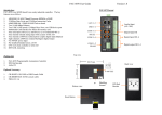
DNA-CAR-550
PCI Express Mini Card
Module Carrier
(for UEIPAC series only)
—
User Manual
February 2010 Edition
Version 1.2
PN Man-DNA-CAR-550-0210
© Copyright 1998-2010 United Electronic Industries, Inc. All rights reserved.
No part of this publication may be reproduced, stored in a retrieval system, or transmitted, in any form
by any means, electronic, mechanical, by photocopying, recording, or otherwise without prior written
permission.
Information furnished in this manual is believed to be accurate and reliable. However, no responsibility
is assumed for its use, or for any infringements of patents or other rights of third parties that may result
from its use.
All product names listed are trademarks or trade names of their respective companies.
See UEI’s website for complete terms and conditions of sale:
http://www.ueidaq.com/company/terms.aspx
Contacting United Electronic Industries
Mailing Address:
27 Renmar Avenue
Walpole, MA 02081
U.S.A.
For a list of our distributors and partners in the US and around the world, please see
http://www.ueidaq.com/partners/
Support:
Telephone:
Fax:
(508) 921-4600
(508) 668-2350
Also see the FAQs and online “Live Help” feature on our web site.
Internet Support:
Support
Web-Site
FTP Site
[email protected]
www.ueidaq.com
ftp://ftp.ueidaq.com
Product Disclaimer:
WARNING!
DO NOT USE PRODUCTS SOLD BY UNITED ELECTRONIC INDUSTRIES, INC. AS CRITICAL
COMPONENTS IN LIFE SUPPORT DEVICES OR SYSTEMS.
Products sold by United Electronic Industries, Inc. are not authorized for use as critical components in
life support devices or systems. A critical component is any component of a life support device or
system whose failure to perform can be reasonably expected to cause the failure of the life support
device or system, or to affect its safety or effectiveness. Any attempt to purchase any United Electronic
Industries, Inc. product for that purpose is null and void and United Electronic Industries Inc. accepts
no liability whatsoever in contract, tort, or otherwise whether or not resulting from our or our
employees' negligence or failure to detect an improper purchase.
Note: Specifications shown in this document are subject to change without notice. Please check with
UEI for current status.
ii
Table of Contents
Chapter 1 Introduction
.................................................... 1
1.1
Organization of this manual . . . . . . . . . . . . . . . . . . . . . . . . . . . . . . . . . . . . . . . . . . . . 1
1.2
DNA-CAR-550 Carrier Board Features. . . . . . . . . . . . . . . . . . . . . . . . . . . . . . . . . . . . 2
1.3
Functional Description . . . . . . . . . . . . . . . . . . . . . . . . . . . . . . . . . . . . . . . . . . . . . . . . 3
1.4
Specifications . . . . . . . . . . . . . . . . . . . . . . . . . . . . . . . . . . . . . . . . . . . . . . . . . . . . . . . 5
1.5
What is PCI Express . . . . . . . . . . . . . . . . . . . . . . . . . . . . . . . . . . . . . . . . . . . . . . . . . . 5
1.6
SIM Card. . . . . . . . . . . . . . . . . . . . . . . . . . . . . . . . . . . . . . . . . . . . . . . . . . . . . . . . . . . 5
1.7
USB 2.0. . . . . . . . . . . . . . . . . . . . . . . . . . . . . . . . . . . . . . . . . . . . . . . . . . . . . . . . . . . . 5
1.8
Wiring & Connectors . . . . . . . . . . . . . . . . . . . . . . . . . . . . . . . . . . . . . . . . . . . . . . . . . . 6
1.9
Inserting the PCI Express Mini Card. . . . . . . . . . . . . . . . . . . . . . . . . . . . . . . . . . . . . . 6
Chapter 2 Connecting to the Internet with CAR-550
............................ 8
2.1
2.1.1
2.1.2
2.1.3
2.1.4
2.1.5
2.1.6
Configuring your PCI Express Mini Card . . . . . . . . . . . . . . . . . . . . . . . . . . . . . . . . . . 8
Prerequisites . . . . . . . . . . . . . . . . . . . . . . . . . . . . . . . . . . . . . . . . . . . . . . . . . . 8
Manual Configuration. . . . . . . . . . . . . . . . . . . . . . . . . . . . . . . . . . . . . . . . . . . . 8
Load Kernel Modules . . . . . . . . . . . . . . . . . . . . . . . . . . . . . . . . . . . . . . . . . . . . 8
Configure Provider . . . . . . . . . . . . . . . . . . . . . . . . . . . . . . . . . . . . . . . . . . . . . . 9
Start PPP Daemon. . . . . . . . . . . . . . . . . . . . . . . . . . . . . . . . . . . . . . . . . . . . . . 9
Automatic Startup . . . . . . . . . . . . . . . . . . . . . . . . . . . . . . . . . . . . . . . . . . . . . 10
2.2
2.2.1
2.2.2
2.2.3
2.2.4
Connecting to a Wifi Network with CAR-550 . . . . . . . . . . . . . . . . . . . . . . . . . . . . . .
Load Kernel Modules . . . . . . . . . . . . . . . . . . . . . . . . . . . . . . . . . . . . . . . . . . .
Connect to an Open Access Point . . . . . . . . . . . . . . . . . . . . . . . . . . . . . . . . .
Connect to an Access Point with WEP Security . . . . . . . . . . . . . . . . . . . . . .
Connect to an Access Point with WPA/WPA2 Security . . . . . . . . . . . . . . . . .
10
10
11
11
11
Chapter 3 Programming with the Low-Level API . . . . . . . . . . . . . . . . . . . . . . . . . . . . . . 13
3.1
Low-Level DqAdv Functions . . . . . . . . . . . . . . . . . . . . . . . . . . . . . . . . . . . . . . . . . . . 13
Apppendix A - Accessories . . . . . . . . . . . . . . . . . . . . . . . . . . . . . . . . . . . . . . . . . . . . . . . . . 15
Index
. . . . . . . . . . . . . . . . . . . . . . . . . . . . . . . . . . . . . . . . . . . . . . . . . . . . . . . . . . . . . . . . . . 16
© Copyright 2010
United Electronic Industries, Inc.
Tel::508-921-4600
Date: February 2010
www.ueidaq.com
Vers: 1.2
DNA-CAR-550-ManualTOC.fm
List of Figures
1-1
1-2
1-3
1-4
1-5
DNA-CAR-550 PCI Express Mini Card Module Carrier Board....................................... 2
UEIPAC Cube with CAR-550 Module Carrier ................................................................ 3
CAR-550, UEIPAC NIC, and PPCx-CPU Assembly ...................................................... 3
Block Diagram of DNA-CAR-550 ................................................................................... 4
Inserting/Removing PCI Express Mini Wireless Card.................................................... 7
© Copyright 2010
United Electronic Industries, Inc.
Tel::508-921-4600
Date: February 2010
www.ueidaq.com
Vers: 1.2
DNA-CAR-550-ManualLOF.fm
DNA-CAR-550 Carrier Board
Chapter 1
Introduction
Chapter 1
Introduction
This document outlines the feature-set and operation of the UEI DNA-CAR-550
PC Express Mini Card module carrier. This board allows direct connection
between a UEIPAC series I/O module and CELL/WIFI networks and also
between a UEIPAC and GPS antennas. It is compatible with CELL/WIFI/GPS
cards from many vendors and also has a standard mini card USB 2.0 interface.
1.1
Organization This DNA-CAR-550 User Manual is organized as follows:
of this manual
•
Chapter 1- Introduction
This section provides an overview of the document content, an overview
of the device architecture, connectivity, and logic of the board.
•
Chapter 2 – Connecting to the Internet with the DNA-CAR-550
This section explains how to connect the UEIPAC to the Internet through
the CAR-550 via PCI Express or USB 2.0. It also describes prerequisites for using the board such as a cell phone data plan, a SIM card, and
account activation. Procedures for manual configuration and automatic
startup are also included in this section.
•
Chapter 3 – Programming with the Low-Level API
This section describes a low level function that may be used to enable
and disable the wireless interface.
•
Appendix – A. Accessories
This appendix contains a list of associated equipment typically used with
the unit.
•
Index
This is an alphabetical listing of topics covered in this manual.
Manual Conventions
To help you get the most out of this manual and our products, please note that
we use the following conventions:
Tips are designed to highlight quick ways to get the job done, or reveal good
ideas you might not discover on your own.
NOTE: Notes alert you to important information.
CAUTION! Caution advises you of precautions to take to avoid
injury, data loss, and damage to your boards or a system crash.
Text formatted in bold typeface generally represents text that should be entered
verbatim. For instance, it can represent a command, as in the following
example: “You can instruct users how to run setup using a command such as
setup.exe.”
©
© CopyrightIndustries,
2010
February
all rights
15, 2010
reserved
Scheidt &
Electronic
Inc.
Bachmann
United Electronic
USA Industries, Inc.
-821-2890
Edit: TBD
Tel: 508-921-4600
www.ueidaq.com
Checked: TBD
www.ueidaq.com
Date:210
ScheidtDate:
& Bachmann
printed
February
February
2010 2010
550_Chap1.fm
Vers: Draft
Vers:
Vers:
1.2
1.0
Fax:
550_Chap1.fm
781-821-2891
1
DNA-CAR-550 Carrier Board
Chapter 1
Introduction
Frequently Asked Questions
For frequently answered questions, application notes, and support, visit us
online:
http://www.ueidaq.com/faq/
1.2
DNA-CAR-550 The DNA-CAR-550 module carrier board has the following features:
Carrier Board
• Allows UEIPAC direct connection to CELL/WIFI networks
Features
• Allows UEIPAC direct connection to GPS antennas
•
Supports CELL/WIFI/GPS cards from many vendors
•
Standard Mini Card USB interface
•
Connects internally to UEIPAC USB port
•
2 external RF/Coax connectors
•
External access for carrier SIM/UIM card
•
Includes replacement faceplate for UEIPAC Cube
•
UEI 10-year Availability Guarantee
Posts for connecting
wireless antenna leads
MAIN (red) and AUX(black)
Sierra Wireless
PCI Express
Mini Card
Figure 1-1. DNA-CAR-550 PCI Express Mini Card Module Carrier
Board
©
© CopyrightIndustries,
2010
February
all rights
15, 2010
reserved
Scheidt &
Electronic
Inc.
Bachmann
United Electronic
USA Industries, Inc.
-821-2890
Edit: TBD
Tel: 508-921-4600
www.ueidaq.com
Checked: TBD
www.ueidaq.com
Date:210
ScheidtDate:
& Bachmann
printed
February
February
2010 2010
550_Chap1.fm
Vers: Draft
Vers:
Vers:
1.2
1.0
Fax:
550_Chap1.fm
781-821-2891
2
DNA-CAR-550 Carrier Board
Chapter 1
Introduction
AUX antenna (if used)
MAIN antenna
Figure 1-2. UEIPAC Cube with CAR-550 Module Carrier
DNA-CAR-550 Layer
NIC Layer
CPU Layer
AUX
Connect to wireless
coaxial connectors
on front panel of
Cube
MAIN
Sierra Wireless
Mini Card (snapped
into place)
Figure 1-3. CAR-550, UEIPAC NIC, and PPCx-CPU Assembly
1.3
Functional
Description
©
© CopyrightIndustries,
2010
February
all rights
15, 2010
reserved
Scheidt &
Electronic
Inc.
Bachmann
United Electronic
USA Industries, Inc.
-821-2890
The purpose of the DNA-CAR-550 is to provide an industry-standard wireless
interface between UEI UEIPAC GigE-based programmable automation
controllers and the Internet. The CAR-550 accepts a standard PCI Express Mini
Card that is compatible with a wide range of COTS cell, WIFI, and other
communication cards, some of which include a direct GPS interface. Note that
only Mini Cards that are based on the USB 2.0 interface are supported by the
CAR-550 board.
Edit: TBD
Tel: 508-921-4600
www.ueidaq.com
Checked: TBD
www.ueidaq.com
Date:210
ScheidtDate:
& Bachmann
printed
February
February
2010 2010
550_Chap1.fm
Vers: Draft
Vers:
Vers:
1.2
1.0
Fax:
550_Chap1.fm
781-821-2891
3
DNA-CAR-550 Carrier Board
Chapter 1
Introduction
The USB connection of the Mini Card is connected directly to the USB port of the
UEIPAC Cube. The minicard driver is part of the Linux kernel; UEI only supports
minicards that are supported by default in Linux. No need for a user to hunt for
proprietary drivers.
The CAR-550 provides a slot and reader for the standard SIM/UIM identity cards
commonly provided by network suppliers. The card may be inserted through the
front panel of the UEIPAC, which allows the user to add or modify service
without having to open the UEIPAC housing.
External RF connections are provided through two standard SMA coaxial.
connectors. RPSMA connectors can also be supplied as an option. The coaxial
connectors for the antenna are mounted directly on the front panel of the Cube
and are connected directly to the Mini Card by flexible leads, as shown in Figure
1-3. These connectors can be used to connect to various antennas for Cell,
WiFi, or GPS devices.
Four annunciator LEDs are provided. One is lit whenever power is on.The others
are controlled by the three LED indicator control pins that are standard with PCI
Express Mini Cards.
The CAR-550 not only provides simple, direct connections to a wide range of
Cell/CDMA/GSM and WiFi networks, but also enables direct connection to the
satellite GPS system.
A functional block diagram of the CAR-550 is illustrated in Figure 1-4 below.
Block Diagram:
PCI Express
Mini Card
LEDs & SMA
SIM/UIM
Card
UEIPAC Internal Bus
DC/DC
USB 2.0
Figure 1-4. Block Diagram of DNA-CAR-550
©
© CopyrightIndustries,
2010
February
all rights
15, 2010
reserved
Scheidt &
Electronic
Inc.
Bachmann
United Electronic
USA Industries, Inc.
-821-2890
Edit: TBD
Tel: 508-921-4600
www.ueidaq.com
Checked: TBD
www.ueidaq.com
Date:210
ScheidtDate:
& Bachmann
printed
February
February
2010 2010
550_Chap1.fm
Vers: Draft
Vers:
Vers:
1.2
1.0
Fax:
550_Chap1.fm
781-821-2891
4
DNA-CAR-550 Carrier Board
Chapter 1
Introduction
1.4
Specifications
The following table lists the technical specifications of the CAR-550 board.
Technical Specifications:
Carrier card type
SIM/UIM card interface
Communications interface
Indicator LEDs
RF connectors
RF connector type
Power dissipation
Operating Temp. Range
Operating Humidity
Vibration IEC 60068-2-6
IEC 60068-2-64
Shock
IEC 60068-2-27
MTBF
PCI Express Mini Card that utilize the
USB Interface
Accepts standard cards from Cell carrier.
May be installed from outside of chassis
USB 2.0
4 provided (1 indicates power is on, 3
are controlled by PCI Express Mini Card)
2
Standard SMA connector
Optional RPSMA connectors also
available
< 1 W, not including PCI Express Card
Tested -40 to +85 °C
95%, non-condensing
5 g, 10-500 Hz, sinusoidal
5 g (rms), 10-500 Hz, broad-band random
50 g, 3 ms half sine, 18 shocks @ 6 orientations
30 g, 11 ms half sine, 18 shocks @ 6 orientations
300,000 hours
1.5
What is PCI
Express
PCI Express is an extension of the PCI bus standard that greatly increases the
bandwidth, range of platforms, and form factors of devices on which it can be
used. It is backward-compatible with old PCI applications but also capable of
handling a much wider variety of current and future systems such as desktop,
mobile, server, communications, workstations, and embedded devices.
1.6
SIM Card
A subscriber identity module (SIM) on a removable SIM card securely stores the
service-subscriber key (IMSI) used to identify a subscriber on mobile telephony
devices such as computers and mobile phones. The SIM card allows users to
change phones (and providers) by simply removing the SIM card from one
mobile phone and inserting it into another mobile phone or broadband telephony
device.
A SIM card contains its unique serial number, international unique number of the
mobile user (IMSI), security authentication and ciphering information, temporary
information related to the local network (also temporary local id that has been
issued to the user), a list of the services the user has access to and two
passwords (PIN for usual use and PUK for unlocking).
SIM cards are available in two standard sizes. The first is the size of a credit card
(85.60 mm × 53.98 mm x 0.76 mm). The newer, more popular miniature version
has a width of 25 mm, a length of 15 mm, and a thickness of 0.76 mm. However,
most SIM cards are still supplied as a full-sized card with the smaller card held
in place by a few plastic links; it can easily be broken off to be used in a phone
that uses the smaller SIM
1.7
USB 2.0
©
© CopyrightIndustries,
2010
February
all rights
15, 2010
reserved
Scheidt &
Electronic
Inc.
Bachmann
United Electronic
USA Industries, Inc.
-821-2890
The USB 1.0 specification was introduced in 1996.for the purpose of making it
easy to connect external devices to PCs by replacing the multitude of
connectors at the back of PCs, addressing the usability problems of existing
interfaces, and to simplify software configuration of all devices connected to the
bus, as well as to permit greater bandwidth for external devices. The original
USB 1.0 specification had a data transfer rate of 12 Mbit/s.
Edit: TBD
Tel: 508-921-4600
www.ueidaq.com
Checked: TBD
www.ueidaq.com
Date:210
ScheidtDate:
& Bachmann
printed
February
February
2010 2010
550_Chap1.fm
Vers: Draft
Vers:
Vers:
1.2
1.0
Fax:
550_Chap1.fm
781-821-2891
5
DNA-CAR-550 Carrier Board
Chapter 1
Introduction
The USB 2.0 specification, which specifies a higher data transfer rate than the
USB 1.0 specification (480 Mbit/s vs.12 Mbit/s) was released in April 2000 and
was standardized by the USB-IF at the end of 2001.
1.8
Wiring &
Connectors
Since the CAR-550 is a wireless device, no external connections, (except the
antennas) are provided for the layer. All non-wireless interconnection between
the CAR-550 and other devices is handled within the Cube housing via the
interlayer bus.
1.9
Inserting the
PCI Express
Mini Card
The recommended procedure for inserting a PCI Express Mini Card into the
receptacle on the CAR-550 is as follows:
STEP 1: Remove power from the UEIPAC and place it on a clean surface.
STEP 2: Remove the four retaining screws from the front panel of the UEIPAC Cube.
STEP 3: Pull the stack of boards out of the front of the UEIPAC.
STEP 4: Locate the receiving connector for the Mini Card on the top of the CAR-550
board. As shown in Figure 1-5, insert the PCI Express Mini Card into the
receiving receptacle and then snap the card into place on the board.
STEP 5: Snap the connectors on the antenna leads onto the color coded MAIN and AUX
posts on the Sierra Wireless Card (See Figure 1-3 on page 3). Carefully align
the boards with the grooves in the UEIPAC housing and then reinsert the stack
of boards into the housing.
STEP 6: Insert the four screws for the front plate into the housing and then reconnect
power, antennas or coaxial cables, if used, and USB cables, if any.
STEP 7: Insert your SIM card and lock into place by sliding the locking tab on the SIM
Card Reader to the left.
STEP 8: Turn on power and verify that the proper LEDs are lit.
This completes the assembly procedure. Refer to Chapter 2 for the startup
procedure for connecting the UEIPAC to the Internet via the CAR-550.
©
© CopyrightIndustries,
2010
February
all rights
15, 2010
reserved
Scheidt &
Electronic
Inc.
Bachmann
United Electronic
USA Industries, Inc.
-821-2890
Edit: TBD
Tel: 508-921-4600
www.ueidaq.com
Checked: TBD
www.ueidaq.com
Date:210
ScheidtDate:
& Bachmann
printed
February
February
2010 2010
550_Chap1.fm
Vers: Draft
Vers:
Vers:
1.2
1.0
Fax:
550_Chap1.fm
781-821-2891
6
DNA-CAR-550 Carrier Board
Chapter 1
Introduction
To remove the Mini Card, follow Steps 1 through 3 above and then pull the two
retaining springs on the Mini Card receptacle away from the card until it
releases. Remove the antenna leads from the Mini Card and then remove the
card from its mating connector. Then follow Steps 5 and 6 above. This completes
the procedure.
Spring Retaining Clips (2)
Figure 1-5. Inserting/Removing PCI Express Mini Wireless Card
©
© CopyrightIndustries,
2010
February
all rights
15, 2010
reserved
Scheidt &
Electronic
Inc.
Bachmann
United Electronic
USA Industries, Inc.
-821-2890
Edit: TBD
Tel: 508-921-4600
www.ueidaq.com
Checked: TBD
www.ueidaq.com
Date:210
ScheidtDate:
& Bachmann
printed
February
February
2010 2010
550_Chap1.fm
Vers: Draft
Vers:
Vers:
1.2
1.0
Fax:
550_Chap1.fm
781-821-2891
7
DNA-CAR-550 Carrier Board
Chapter 2
Connecting to the Internet with CAR-550
Chapter 2
2.1
Configuring
Your PCI
Express Mini
Card
Connecting to the Internet with CAR-550
The CAR-550 is a carrier card for PCI Express Mini Cards. Those mini cards can
interface with a host using either PCI Express or USB 2.0 connectivity.
The CAR-550 only gives access to the USB 2.0 connectivity. It connects the PCI
Express mini card USB pins to the USB host port on the CPU layer.
Although you can use the CAR-550 with various types of PCI Express mini
cards, this manual focuses on using a Sierra wireless MC8790 card that offers
UMTS/HSPA and quad-band GSM/GPRS/EDGE network access for roaming on
high-speed networks worldwide.
Note that CAR-550 is only supported by the UEIPAC.
2.1.1
Prerequisites
You need to purchase a data plan with a cell phone provider that supports UMTS
and/or GSM/GPRS. ATT and T-Mobile provide such a service in the USA.
Once you purchase a data plan, you will receive a SIM card that you need to
insert in the CAR-550 before being able to establish a connection.
Don't forget to activate your account as soon as you receive your SIM card
(usually done over the phone or on-line).
2.1.2
Manual
Configuration
From the UEIPAC point of view, the wireless modem is seen as a serial port to
which it can send Hayes AT commands as if it were an old fashioned RTC
modem.
UEIPAC uses the PPP software to control the modem and configure a network
connection with your phone provider.
2.1.3
Load Kernel
Modules
At the command line prompt, type the following commands:
modprobe sierra
modprobe ppp
You should see the following messages printed on the console:
~ # modprobe sierra
usbcore: registered new interface driver usbserial
usbserial: USB Serial Driver core
USB Serial support registered for Sierra USB modem
sierra 1-1:1.0: Sierra USB modem converter detected
usb 1-1: Sierra USB modem converter now attached to
ttyUSB0
sierra 1-1:1.1: Sierra USB modem converter detected
usb 1-1: Sierra USB modem converter now attached to
ttyUSB1
sierra 1-1:1.2: Sierra USB modem converter detected
usb 1-1: Sierra USB modem converter now attached to
ttyUSB2
sierra 1-1:1.3: Sierra USB modem converter detected
usb 1-1: Sierra USB modem converter now attached to
ttyUSB3
sierra 1-1:1.4: Sierra USB modem converter detected
usb 1-1: Sierra USB modem converter now attached to
ttyUSB4
sierra 1-1:1.5: Sierra USB modem converter detected
©
© CopyrightIndustries,
2010
February
all rights
15, 2010
reserved
Scheidt &
Electronic
Inc.
Bachmann
United Electronic
USA Industries, Inc.
-821-2890
Edit: TBD
Tel: 508-921-4600
www.ueidaq.com
Checked: TBD
www.ueidaq.com
Date:210
ScheidtDate:
& Bachmann
printed
February
February
2010 2010
550_Chap2.fm
Vers: Draft
Vers:
Vers:
1.2
1.0
Fax:
550_Chap2.fm
781-821-2891
8
DNA-CAR-550 Carrier Board
Chapter 2
Connecting to the Internet with CAR-550
usb 1-1: Sierra USB modem converter now attached to
ttyUSB5
sierra 1-1:1.6: Sierra USB modem converter detected
usb 1-1: Sierra USB modem converter now attached to
ttyUSB6
usbcore: registered new interface driver sierra
sierra: v.1.3.2:USB Driver for Sierra Wireless USB
modems
~ # modprobe ppp
PPP generic driver version 2.4.2
2.1.4
Configure
Provider
The system is pre-configured to connect to ATT network. If you are using a
different provider, edit the file /etc/ppp/peers/gsm_chat
Look for the following line:
OK
'AT+CGDCONT=1,"IP","ISP.CINGULAR"'
Replace it with the APN (Access Point Name) of your provider.
For example, T-mobile's APN is “epc.tmobile.com”, so the line in
/etc/ppp/peers/gsm_chat becomes:
OK
2.1.5
Start PPP
Daemon
'AT+CGDCONT=1,"IP","EPC.TMOBILE.COM"'
Issue the following command to start the PPP daemon and configure the network connection.
/etc/init.d/pppd start
After a few seconds, the script will return printing the message “[OK]” if it successfully configured the network connection or “[Failed]” if it did not.
~ # /etc/init.d/pppd start
Starting pppd...PPP BSD Compression module registered
PPP Deflate Compression module registered[ OK ]
In case of failure, type the command “dmesg” to print the log and send that
information to UEI technical support.
Type the command “ifconfig” to print the network connections currently
configured on your UEIPAC. There should be three connections: local, eth0 and
ppp0.
eth0
Link encap:Ethernet
HWaddr 00:0C:94:00:C5:CB inet addr:192.168.100.2
Bcast:192.168.100.255 Mask:255.255.255.0
UP BROADCAST RUNNING MULTICAST MTU:1500
Metric:1RX packets:0 errors:0 dropped:0 overruns:0
frame:0 X packets:0 errors:0 dropped:0 overruns:0
carrier:0 collisions:0 txqueuelen:1000
RX bytes:0 (0.0 B) TX bytes:0 (0.0 B)
Base address:0x4000
lo Link encap:Local Loopback
inet addr:127.0.0.1 Mask:255.0.0.0
UP LOOPBACK RUNNING MTU:16436 Metric:1
RX packets:0 errors:0 dropped:0 overruns:0
frame:0 X
packets:0 errors:0 dropped:0 overruns:0 carrier:0
collisions:0 txqueuelen:0
©
© CopyrightIndustries,
2010
February
all rights
15, 2010
reserved
Scheidt &
Electronic
Inc.
Bachmann
United Electronic
USA Industries, Inc.
-821-2890
Edit: TBD
Tel: 508-921-4600
www.ueidaq.com
Checked: TBD
www.ueidaq.com
Date:210
ScheidtDate:
& Bachmann
printed
February
February
2010 2010
550_Chap2.fm
Vers: Draft
Vers:
Vers:
1.2
1.0
Fax:
550_Chap2.fm
781-821-2891
9
DNA-CAR-550 Carrier Board
Chapter 2
Connecting to the Internet with CAR-550
RX bytes:0 (0.0 B) TX bytes:0 (0.0 B)
ppp0
Link encap:Point-to-Point Protocol
inet addr:166.203.211.199
P-t-P:10.64.64.64 Mask:255.255.255.255
UP POINTOPOINT RUNNING NOARP MULTICAST
MTU:1500 Metric:1 RX packets:14 errors:0 dropped:0
overruns:0 frame:0 TX packets:15 errors:0 dropped:0
overruns:0 carrier:0 collisions:0 txqueuelen:3
RX bytes:182 (182.0 B) TX bytes:257 (257.0 B)
Make sure that ppp0 was assigned an IP address.
You can now connect to the internet from your UEIPAC.
2.1.6
Automatic
Startup
To automatically load the kernel modules, edit the file /etc/modules and add the
following lines at the end of the file:
sierra
ppp
To automatically start the ppp daemon, add a symbolic link to /etc/init.d/pppd
in the directory /etc/rc.d with the following command:
ln -s /etc/init.d/pppd /etc/rc.d/S30pppd
2.2
Connecting
to a Wifi
Network with
CAR-550
The UEIPAC comes with drivers for Wifi network usb interfaces that use the
following chipsets:
•
Realtek RTL8187
•
Ralink RT2570, RT2571
To connect a CAR-550 to a WiFI network, use the following procedure:
2.2.1
Load Kernel
Modules
At the command line prompt, type one of the following commands depending on
the wifi chipset you are using:
modprobe
modprobe
modprobe
modprobe
rtl8187
rt200xusb
rt2500usb
rt73usb
Wifi network interface are names wlan0, wlan1, etc…
The iwconfig utility is used to configure wifi communication parameters.
You can verify that your interface was properly detected by typing the command
iwconfig.
A new entry wlan0 should appear:
lo
eth0
eth1
wmaster0
wlan0
©
© CopyrightIndustries,
2010
February
all rights
15, 2010
reserved
Scheidt &
Electronic
Inc.
Bachmann
United Electronic
USA Industries, Inc.
-821-2890
no wireless extensions.
no wireless extensions.
no wireless extensions.
no wireless extensions.
IEEE 802.11bg ESSID:""
Mode:Managed Frequency:2.412 GHz
Access Point: Not-Associated
Tx-Power=0 dBm
Edit: TBD
Tel: 508-921-4600
www.ueidaq.com
Checked: TBD
www.ueidaq.com
Date:210
ScheidtDate:
& Bachmann
printed
February
February
2010 2010
550_Chap2.fm
Vers: Draft
Vers:
Vers:
1.2
1.0
Fax:
550_Chap2.fm
781-821-2891
10
DNA-CAR-550 Carrier Board
Chapter 2
Connecting to the Internet with CAR-550
Retry min limit:7
RTS thr:off
Fragment thr=2352 B
Encryption key:off
Power Management:off
Link Quality:0 Signal level:0
Noise level:0
Rx invalid nwid:0 Rx invalid crypt:0
Rx invalid frag:0
Tx excessive retries:0 Invalid misc:0
Missed beacon:0
2.2.2
Connect to an Specify that you want to connect as a client to a network with an access point:
Open Access
iwconfig wlan0 mode managed
Point
STEP 1: Set the ESSID of the access point:
iwconfig wlan0 essid <name of your access point>
STEP 2: Bring up the wifi interface:
ifconfig wlan0 up
You can now scan the access points accessible by your wifi interface:
iwlist wlan0 scan
If there is a DHCP server on your network, get an IP address for your wifi
interface:
udhcpc –i wlan0 –s /etd/udhcpc/default.script
Otherwise, assign a static IP address to your wifi interface:
ifconfig wlan0 192.168.100.3 netmask 255.255.255.0
route add default gateway 192.168.100.1
2.2.3
Connect to an The procedure is almost identical to connecting to an open access point. In
Access Point addition, you need to specify your WEP key, as follows:
with WEP
iwconfig wlan0 key <WEP key in hexadecimal>
128 bit WEP uses 26 hex characters, 64 bit WEP uses 10
Security
2.2.4
Connect to an Generate the pre-shared key using the access point’s password:
Access Point
wpa_passphrase <name of your access point>
with WPA/
<access point password>
WPA2
Edit the file /etc/wpa_supplicant.conf and update the ssid and psk entry to
Security
match the key generated by wpa_passphrase
ctrl_interface=/var/run/wpa_supplicant
ctrl_interface_group=0
©
© CopyrightIndustries,
2010
February
all rights
15, 2010
reserved
Scheidt &
Electronic
Inc.
Bachmann
United Electronic
USA Industries, Inc.
-821-2890
Edit: TBD
Tel: 508-921-4600
www.ueidaq.com
Checked: TBD
www.ueidaq.com
Date:210
ScheidtDate:
& Bachmann
printed
February
February
2010 2010
550_Chap2.fm
Vers: Draft
Vers:
Vers:
1.2
1.0
Fax:
550_Chap2.fm
781-821-2891
11
DNA-CAR-550 Carrier Board
Chapter 2
Connecting to the Internet with CAR-550
ap_scan=1
network={
ssid=<put your access point ESSID here>
proto=WPA
key_mgmt=WPA-PSK
pairwise=TKIP
group=TKIP
psk=<put your pre-shared key generated with
wpa_passphrase here>
priority=2
}
Specify that you want to connect as a client to a network with an access point in
managed mode:
iwconfig wlan0 essid <name of your access point>
mode managed
Run wpa_supplicant in daemon mode to authenticate with the access point:
wpa_supplicant –iwlan0 –c/etc/wpa_supplicant.conf –
Dwext –B
Run iwconfig to verify that the authentication worked:
wlan0
IEEE 802.11bg ESSID:"fred"
Mode:Managed Frequency:2.447 GHz Access Point:
00:13:10:AA:FA:10
Bit Rate=1 Mb/s
Tx-Power=27 dBm
Retry min limit:7
RTS thr:off
Fragment thr=2352 B
Encryption key:B507-40C4-9A48-806D-D664910F-B354-6CF4-DEBF-EA54-CE6F-B291-BD0E-593F-BFA9405D [2]
Security mode:open
Power Management:off
Link Quality=80/100 Signal level:-31 dBm
Rx invalid nwid:0 Rx invalid crypt:0
Rx invalid frag:0
Tx excessive retries:0 Invalid misc:0
Missed beacon:0
If there is a DHCP server on your network, get an IP address for your wifi
interface:
udhcpc –i wlan0 –s /etc/udhcpc/default.script
Otherwise, assign a static IP address to your wifi interface, as follows:
ifconfig wlan0 192.168.100.3 netmask 255.255.255.0
route add default gateway 192.168.100.1
©
© CopyrightIndustries,
2010
February
all rights
15, 2010
reserved
Scheidt &
Electronic
Inc.
Bachmann
United Electronic
USA Industries, Inc.
-821-2890
Edit: TBD
Tel: 508-921-4600
www.ueidaq.com
Checked: TBD
www.ueidaq.com
Date:210
ScheidtDate:
& Bachmann
printed
February
February
2010 2010
550_Chap2.fm
Vers: Draft
Vers:
Vers:
1.2
1.0
Fax:
550_Chap2.fm
781-821-2891
12
DNA-CAR-550 Carrier Board
Chapter 3
Programming with the Low-Level API
Chapter 3
Programming with the Low-Level API
The low-level API offers direct access to PowerDNA DaqBIOS protocol and
allows you to access device registers directly.
Please refer to the API Reference Manual document under:
Start » Programs » UEI » PowerDNA » Documentation
for pre-defined types, error codes, and functions for use with this board.
NOTE: High-level UEI Framework support for this layer is not available in the
current release of the CAR-550 board.
At present, only one low-level function is available for use with the CAR-550
board, as described below:
3.1
Low-Level
DqAdv
Functions
DqAdvSetWirelessState( )
•
Syntax:
DqAdvSetWirelessState(int hd, int devn, uint32 cmd,
uint32 data)
• Command:
DQE
Input
int hd
Handle to the IOM received from DqOpenIOM()
int devn
Layer inside the IOM
uint32 cmd
What parameter to set
uint32 data
Value depending on cmd parameter.
If cmd is DQ_CAR550_WIRELESS_EN_DIS, data is 32-bit value to
enable or disable wireless system. Zero to disable wireless, non-zero
to enable.
Output
None
Return
DQ_ILLEGAL_HANDLE
Illegal IOM Descriptor or communication wasn’t established.
DQ_BAD_DEVN
Device indicated by devn does not exist or is not a CAR-550.
DQ_SEND_ERROR
Unable to send the Command to IOM.
DQ_TIMEOUT_ERROR
Nothing is heard from the IOM for Time out duration.
DQ_IOM_ERROR
Error occurred at the IOM when performing this command.
DQ_SUCCESS
Successful completion.
Other negative values
Low level IOM error.
©
© CopyrightIndustries,
2010
February
all rights
15, 2010
reserved
Scheidt &
Electronic
Inc.
Bachmann
United Electronic
USA Industries, Inc.
-821-2890
Edit: TBD
Tel: 508-921-4600
www.ueidaq.com
Checked: TBD
www.ueidaq.com
Date:210
ScheidtDate:
& Bachmann
printed
February
February
2010 2010
550_Chap3.fm
Vers: Draft
Vers:
Vers:
1.2
1.0
Fax:
550_Chap3.fm
781-821-2891
DNA-CAR-550 Carrier Board
Chapter 3
Programming with the Low-Level API
• Description:
This function is used to enable or disable the wireless interface installed on a
CAR-550.
• Note:
None.
©
© CopyrightIndustries,
2010
February
all rights
15, 2010
reserved
Scheidt &
Electronic
Inc.
Bachmann
United Electronic
USA Industries, Inc.
-821-2890
Edit: TBD
Tel: 508-921-4600
www.ueidaq.com
Checked: TBD
www.ueidaq.com
Date:210
ScheidtDate:
& Bachmann
printed
February
February
2010 2010
550_Chap3.fm
Vers: Draft
Vers:
Vers:
1.2
1.0
Fax:
550_Chap3.fm
781-821-2891
DNA-CAR-550 Carrier Board
Appendix
A. Accessories
This appendix provides a list of accessories typically used with CAR-550 carrier
board(s). They are all available from a number of suppliers.
© Copyright 2010
United Electronic Industries, Inc.
•
PCI Express Mini Cards
•
SIM/UIM Cards
•
Coaxial Cables with SMA or RPSMA (reverse polarity) connectors
Tel: 508-921-4600
Date: February 2010
www.ueidaq.com
Vers: 1.2
File: 550_Appx.fm
15
16
Index
A
Accessories 16
Automatic Startup
B
Block Diagram
M
Manual Configuration
10
O
Organization
4
C
Configure Provider
8
1
P
PCI Express 5
Prerequisites 8
Programming with the Low-Level API
9
F
Features 2
Functional Description
I
Inserting the Mni Card
L
Load Kernel Modules
14
S
3
SIM Card 5
specifications 5
Start PPP Daemon
6
U
USB 2.0
8
9
5
W
Wiring 6
© Copyright 2010
United Electronic Industries, Inc.
Tel: 508-921-4600
Date: February 2010
www.ueidaq.com
Vers: 1.2
File: DNA-CAR-550-ManualIX.fm