1
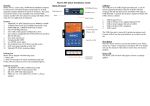
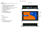
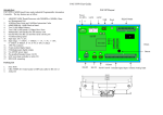
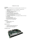
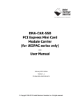
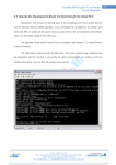
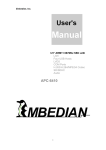
PAC-4070 User Guide
Version 1.0
Introduction:
PAC-4070 is an ARM9-based Linux ready industrial controller. The key
features are as follow:
1.
2.
3.
4.
5.
6.
7.
8.
9.
10.
11.
12.
13.
14.
ARM926EJ-S ARM Thumb Processor 400MHz w/MMU
32-KByte Data Cache and 32-KByte Instruction Cache
64MB SDRAM, 128MB NAND Flash on board
Two 10/100 Mbps Ethernet
Two USB 2.0 full speed (12 Mbps) Host Ports, one USB device port
Multimedia Card Interface for Micro SD memory card
Four serial ports: RS-232 x2 and RS-232 x2 or Isolated RS-485 x2
Four channel isolated analog input with accurate 16-bit A/D
Four channels 2500Vrms isolated photo coupler digital input (Bipolar)
Eight channels 2500Vrms isolated Darlington digital output
9 to 40VDC power input
Pre-installed Standard Linux 2.6 OS
GNU tool chain available in Artila CD
DIN RAIL mounting
Packing List
1.
2.
3.
PAC-4070 Layout
LAN 1~2
COM 1~2
Digital Input DI1
RS-232
COM 3~4
Digital Input DI2~4
COM 1~2
RS-485
Digital output DO1~4
Top view
PAC-4070 Programmable Automation Controller
DIN Rail bracket
Artila CD
102.5 mm
Back view
65 mm
Optional Accessory:
1.
2.
3.
Analog Input
(AI1~AI4)
USB 1~2
CB-RJ45F9-150: RJ45 to DB9 Female Cable
CB-BHDB9-020: M-502 console cable
PWR-12V-1A
9~40 VDC
V+
VBottom view
Reset Button
Shielding
Ground
DIN Rail
Bracket
Pin Assignment and Definition
Reset Button
Press the “Reset” button to activate the hardware reset.
You should only use this function if the software does
not function properly.
Power LED
The Power LED will show solid green if power is
properly applied
Ready LED
The Ready LED will show solid green if PAC-4070
complete system boot up. If Ready LED is off during
system boot up, please check if power input is correct.
Turn off the power and restart PAC-4070 again. If
Ready LED is still off, please contact the manufacture
for technical support.
Link and Act LED
When Ethernet port are connected to the network, Link
LED will show solid green. If there is traffic is the
Ethernet line, the yellow Act LED will flash.
Serial Port LED
When RXD line is high then Yellow light is ON and
when TXD line is high, Green light is ON.
Ethernet Port
Serial Console Port:
Serial console port is located inside the box at JP4 of M502. You need a special console cable (CB-BHDB9-020) to
access it
1
2
3
4
TxD
RxD
VCC3
GND
TxD: RS-232 transmit
RxD: RS-232 receive
VCC3: 3.3 VCC Output
GND: Signal ground
Use any terminal software such as hyper terminal and configure
the setting as follow:
Baud Rate: 115200
Data bits: 8
Parity: N
Stop bit: 1
Terminal type: VT100
Note : We provide a utility software, setconsole to redirect
the console port to any one of the serial port. Therefore user
do not need to open the case to access the physical console
port. Please refer to setconsole command in the Artila
utility section.
Serial Ports:
Port 1~2: Software selectable RS-232 or isolated RS485. If RS-485 is chosen, please use terminal block
connector for RS-485.
Port 3~4: RS-232 port with hardware flow control
Note: Only Port 2 support RS-232 full modem control
DSR,DCD and DTR.
Analog input block diagram
Power Input Connector
PAC-4070 uses +9VDC to 40VDC power and input from
three ports plug-in screw terminal connector. Auto-polarity
and surge protection are included in power input circuitry
of PAC-4070 to provide power protection. Shielding
ground provides better EMI protection. Please wire the
shielding ground to an appropriate grounded metal surface
V/A
+
_
PGA
120 Ω
Digital Input Connector
The 4 channel isolated input are equipped with 2500 Vrms
photo coupler . DI1 uses DI.GND and DI2 to DI4 share
command ground, DI COM. The specification of the
isolated input channels are:
ADC
DC
Analog Input Connector (AI+, AI-)
Each of the 4 channels isolated analog input can be configured
as various input range and the common features are show as
follow:
Effective Resolution: 16-bit
Channels: four differential input channels
Input Type: mV, V, mA
Input Range:
Uni-polar:0~150mV, 0~500mV, 0~1V, 0~5V, 0~10V
Bi-polar: +/- 150mV, +/- 500mV, +/- 1V, +/- 5V, +/- 10V
Current: 0~20mA
Sampling rate: 10~100 samples /sec
Input Impedance: 20 M Ohm
Accuracy: +/- 0.1%
CMR: 50/60 Hz 100dB
Isolation: 1500Vrms (Three-way)
The analog input channels provide 1500Vrms isolation.
Therefore, to measure a floating signal such as a battery and
single-ended source, simply connect the positive signal to AI+
and negative (ground) signal to AI– to perform a differential
measurement.
To measure current input, please set the jumper (JP1~JP4) to
position 2-3 to shunt the 120 ohm resistor on board for current
measurement.
Input Type Selection Jumper JP1~JP4
1
3
Voltage Input: 1-2 (default)
Current Input: 2-3
DC
Digital Output Connector (DO1~DO4, DO GND, DO VCC)
The digital output are equipped with 4 darlington pair
transistors (Allegro UDN2981A) to switch the external relay
or solenoid. The internal transient-suppression diodes permit
the drive to be used with inductive load. The source voltage
of the drive is from 5Vdc to 50 Vdc and the maximum
driving current is 500 mA. 2500 Vrms isolation is provided
in all 4 DO ports.
DO VCC
Power
5~50V
DOX
Relay
DO GND
DOX: DO output channels
DO GND: Ground of DO (Darlington)
DO VCC: External voltage source of DO
Logical High: 5~24Vdc
Logical Low: 0~1.5Vdc
Input resistance: 1.2KOhms @0.5W
Response time: 20us
Isolation: 2500Vrms
DI1, DI2~4
DIGND,DICOM
DIx: Isolated digital input channels
DI GND: ground of DI1
DI COM: common ground of DI2~DI4
Factory Default Settings
LAN 1 IP Address: 192.168.2.127
LAN 2 IP Address: 192.168.3.127
Login: root or guest ( telnet guest only)
Password: root or guest ( telnet guest only)
Serial Console Port:
Baud rate: 115200
Data format: 8 Bits, No Parity, 1 Stop bit (N,8,1)
Flow Control: None
Terminal type: VT100
Default started service
1.
amgrd (Artila broadcast search daemon)
2.
ssh (secured shell) with sftp
3.
syslog/klogd (system and kernel log)
4.
telnet server (disable root with /etc/securetty)
5.
ftp server (vsftp)
6.
web server (apache2)
7.
Ready LED (debug LED for internal use)
Network Settings
Power on and System boot up
Once PAC-4070 is correctly power on, it will start boot Linux
kernel and mount file system. You can use Ethernet and telnet
and login PAC-4070. Once kernel loaded, it will find /sbin/
init and execute it. The initialization configuration is at /etc/
inittab. Once boot up, you can use telnet to login PAC-4070.
Use vi editing tool to edit the /etc/network/interfaces for network
setting. The default setting is static IP 192.168.2.127. PAC-4070
also supports Wireless LAN. Use
wireless_essid XXX
wireless_key YYY
To add SSID and WEP key if necessary. XXX is SSID and YYY
is WEP Key
PAC-4070 supports USB WLAN adaptor (Ralink RT2571). You
can enable the driver module (rt73usb) by adding rt73usb in
/etc/modules
File System
The 128MB NAND Flash memory of PAC-4070 contains Boot
loader (uBoot), Linux Kernel, Root File System and user disk
(\home). The file system and disk space are shown as follow
Insert kernel module
To insert kernel module while system boot up, please use vi to
edit /etc/modules to add module to load e.g.
Inittab and Run levels:
Inittab contains information of system initialization. The
system initialization script /etc/rcS.d runs first then the run
level 5 /etc/rc5.d PAC-4070 uses run level for system setup
and the default run level is number 5. Please refer to
introduction to linux (http://tille.garrels.be/training/tldp/) for
information about run level. Following is the run levels
setting:
Run level 0: halt
Run level 1 is single user ( login and service are disabled )
Run level 2~5 are multiple users
Run level 6 is reboot.
Please refer to loader menu section for selection of run level
rt73usb
To load the USB WLAN adaptor.
Devices list
The supported devices are shown at /dev directory. Following
list are most popular ones:
1.
ttyS0: serial console port
2.
ttyS1 to ttyS4: serial port 1 to port 4
3.
sda to sdb: USB flash disk
4.
ttyUSB0 to ttyUSB1: USB RS-232 adaptor (fdti_sio.ko)
5.
rtc: Real Time Clock
6.
gpio: Digital I/O
7.
adc: A/D channel
8.
ttyACM0 and ttyACM1: USB Modem (CDC compliant)
9.
mmc : SD driver
Mounting External Storage Memory
To find out the device name of the external memory device
which plug into PAC-4070, you can use the command
dmesg | grep sd
dmesg | grep mmc
To find out the device type (sda , sdb or mmc)
And use
mount /dev/sda1
mount/dev/mmc
to mount the USB disk or SD card and folder is local at
media/sda1 or /mnt/sda1
SSH Console
PAC-4070 supports SSH. If you use Linux computer, you can
use SSH command to login PAC-4070. The configuration of
SSH and key are located at
/etc/ssh
The key generation program is available at /usr/bin
Welcome Message
To modify the welcome message, user can use text edit to
modify the /etc/motd.
Putty Console Software
For Windows user, you can download the putty software at
http://www.chiark.greenend.org.uk/~sgtatham/putty/
download.html to use SSH to login PAC-4070
Utility Software:
PAC-4070 includes busybox utility collection and Artila
utility software and there are placed at :
/sbin
/bin
/usr/bin
/use/sbin
Please refer to Appendix for the utility collection list
Web Page Directory
The web pages are placed at /usr/www and the
/etc/lighttpd.conf contains the lightttpd web server settings. The
home page name should be index.html
Adjust the system time
To adjust the RTC time, you can follow the command
date MMDDhhmmYYYY
where
MM=Month (01~12)
DD=Date (01~31)
hh=Hour
mm=minutes
YYYY= Year
hwclock –w
To write the date information to RTC
User can also use NTP client utility in Artila CD to adjust the
RTC time.
ntpclient [time server ip]
ipkg package software management
ipkg is a light software package utility. It can be used to
install, upgrade and remove the software package for PAC4070. Currently user can use ipkg to install the software
package from Artila FTP. You can find the configuration at
ipkg.conf
When PAC-4070 is connected to network and issue command
ipkg update
To update the package list and use
ipkg install
to install software package and
ipkg remove
to remove software
ipkg list
to list available software
ipkg list_installed
to list software installed
Please refer to Appendix for more about ipkg
Install GNU Tool Chain
Find a PC with Linux OS installed as followed:
Fedore 7, ubuntu 7.04, OpenSUSE 10.2, Mandriva 2008,
Debian 5.0, Centos (RedHat) 5 and above.
Login as a root user then copy the arm-linux-4.3.2.tar.gz to root
directory of PC. Under root directory, type following command
to install the PAC-4070 Tool Chain
#tar -xvfj arm-linux-4.3.3.tar.bz2
The tool chain file name are
arm-linux-gnueabi-gcc
arm-linux-gnueabi-g++
arm-linux-gnueabi-strip
Version: gcc 4.3.3, glibc 2.9, binutils 2.18
For Windows user, please download the toolchain from
CodeSourcery at
http://www.codesourcery.com/sgpp/lite/arm/portal/
package4547/public/arm-none-linux-gnueabi/arm-2009q1-203arm-none-linux-gnueabi.exe
The tool chain file name are
arm-none-linux-gnueabi-gcc
arm-none-linux-gnueabi-g++
arm-none-linux-gnueabi-strip
Version: gcc 4.3.3, glibc 2.8, binutils 2.19
Getting started with the Hello program
There are many example programs in Artila CD. To compile the
sample you can use the Make file and type
make
To compile and link the library. Once done, use ftp command
ftp 192.168.2.127
Then login with password. Use bin command to set transfer
mode to binary
ftp>bin
to transfer the execution file to PAC-4070 user disk (/home/
guest) and use
chmod +x file.o
To change it to execution mode and
./file.o
to run the program
Auto start program on boot:
To start a program on boot, you can use /etc/rc.local
For example to use vi to edit rc.local
hello &
exit 0
Hello will be executed after system boot up. rc.local has the
similar function as /etc/rc in PAC-4070
Artila Utility Software:
The introduction of Artila utility software as follow:
1. update : update loader, environment file and kernel image.
Type update—help to find the command usage
3. version: find out the version of OS.
4. gpioctl: The gpio can be configured by gpioctl and the
usage is as shown followed.
Note: Update can only operated under supervisor mode
(password : root). Please use command su and login as root
2. setuart: configure serial port setting. An example show as
followed to configure port 1 as RS-485 interface with baud
rate 921600.
3. setconsole: PAC-4070 is designed to use M-502 SoM as its
CPU module. The console port is located at JP4 of M-502
module. User can use setconsole command to redirect the
serial console port to any one of the four serial port of PAC4070. Therefore user can avoid opening the metal case to
access the serial console.
5. setadc: setadc is used to configure the analog input channels.
How to read Analog Input data
To read the analog data of the input channel, please follow the
steps below:
1.
2.
Set the configuration of the analog channels [adc0~adc3]
Repeatedly read data from the device [adc0~adc3]
Note: Please set the delay time to be 100ms or longer if you
want to perform multiple channels scan. The ADC device
driver will delay 100 ms for Multiplexer and
Programmable Gain Amplifier to be stable before taking
the data from ADC.
Loader Menu
Loader menu helps user to select the run level of system boot
up. User need to use serial console to enter loader menu.
Please configure the serial port of terminal as follow:
Baud Rate: 115200
Data bits: 8
Parity: N
Stop bit: 1
Flow Control: None
Terminal type: VT100
Frequently Asked Question
1. Forgot password:
If you forgot the password for login, please use serial console and
use run level 1 to boot system. Use passwd to change the password
setting.
Once power up PAC-4070, please repeatedly keying “@” and
you will see the loader menu appear as follow:
2. Forgot the IP address
If you forgot the PAC-4070 IP address, you can use the Java
Manager available in Artila CD to search the IP address of PAC4070 Or use serial console port to find out the IP address by
#ifconfig
If you miss the timing, please power on again the PAC-4070
and do it again. Select U will prompt the run level selection
message. Run level 0 is halt, run level 1 is single user
( disable login and service ). Run level 2~5 are multiple
users and run level 6 is reboot. To view the run level
configuration, please check
/etc/inittab
3. System fail to boot
If you mess up the root file system and make the system fail to boot,
PAC-4070 will automatically switch to boot from Dataflash file
system and a console menu will show up at console port to help user
perform system recovery. System Recovery Section will tell you
how to recover the system.
System Recovery
Update Image Starts
Make Files System Starts
If NAND Flash file system does fail, DataFlash file system
will automatically boot up and a Console Menu at console
port will appear as follow:
Update Image Completes
Note:
1. Update Image: this option can recover the loader, kernel
and file system by using an USB disk. The USB disk
contains the images files with the path as follow:
Loader: pac4000/pac4000.alf
Kernel: pac4000/pac4000K
File system: pac4000/pac4000R
The files are available in Artila CD. Please prepare an USB
disk and copy the image files to it before choosing this
option.
Make user’s filesystem
2. Make Filesystem: this option is used to create customized
file system. Before using this function, you need to copy the
folder of mkimage504 in the Artila CD to an USB disk. This
function will create a new file system image for users and
they can use it to duplicate the customized file system to other
PAC-4010.
Recover Environment File
3. Recovery Env.: The option will recover the environment
files as default setting. Use this function only when the
NAND file system crash.
4. Show Info: Show the version information of PAC-4070
5. Reboot: Reboot the NAND flash file system.
1.
2.
Use Arrow keys up and down to selection the functions
Use Arrow keys left and right to go to higher or lower levels
of menu screen
Force DataFlash boot
1.
To force system go into DataFlash booting, repeatedly
keying “!” (Shift +1 ) right after PAC-4070 power on.
Appendix
Utility Collection
ipkg software package management
The webmin for PAC-4070 provides following modules:
1.
2.
3.
4.
5.
6.
7.
8.
9.
10.
11.
12.
13.
14.
15.
16.
PAC-4070 uses ipkg to manage the software installation, upgrade and
removal. Artila will continuously add the kernel module and utility at
our ftp server, user can install these software from Artila’s ftp server. In
addition user can also setup your ftp server to update the software you
want. To install the utility from Artila ftp, please use vi to edit the /etc/
ipkg.conf
src/gz arm ftp://ftp:[email protected]/AT9G20/Artila-CD/Linux/Utility
src/gz kernel ftp://ftp:[email protected]/AT9G20/Artila-CD/Linux/
modules
1.
2.
3.
4.
5.
6.
You can also copy the Utility and module folder from Artila CD to a
USB disk, then use USB disk to install the software by changing the
ipkg.conf
src/gz usb_arm ftp://root:[email protected]/media/sda1/Utility
src/gz usb_kernel ftp://root:[email protected]/media/sda1/modules
depmod –a /lib/modules/2.6.29.4/modules.dep
busybox v1.14.2-tiny utility collection
sysvinit v2.86 -standard Linux initialization
util-linux-mount/umount v2.12r-support long file name
ssh v4.6p1– support sftp server
usbutils v0.7– USB id program
lighttpd v 1.7-web server
wget v1.9.1– used in ipkg software
iptables v1.3.8– IP routing
ipkg v.0.99.163– software package management
procps v3.2.7– support webmin process management
vsftpd v2.0.5– ftp server
bash v3.2-GNU shell
wireless_tools v29– wireless LAN utility
ppp v2.4.3-ppp dial up utility
psmics v22.2– procps supplement
artila utility v.1.1– handy utility added by Artila
You can find more utility at Artila Matrix-504 CD and use
ipkg to install the utility.
Make sure the USB disk is correctly mounted, now use command
ipkg update
to update the package list and use
ipkg install webmin
To install webmin. Webmin is a web-based interface to system
administration. To start webmin, go to /etc/webmin and type
start webmin
Then you can use browser to visit PAC-4070 port 10000
Webmin: webmin configuration
System: system boot, process and log management
Server: Apache and SSH server configuration
Network: network configuration
Hardware: RTC setting
Others: File manager, upload and download
Remember to use command
To update the dependency list if new kernel module
were added.