1
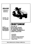
OWNERS
MANUAL
MODEL NO.
917.255919
Caution:
Read and Follow
All Safety Rules
And instructions
Before Operating
This Equipment
GT 18HP TWiN
6 SPEED - 44"" MO WER
GARDEN TRACTOR
Assembly
Operation
Maintenance
Repair
Repair
Sears,
Roebuck
and Co.
and Adjustment
Parts
Chicago,
IL 60684
U_S,Ao
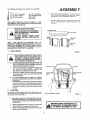
LOOK FOR THIS SYMBOL TO POINT
OUT IMPORTANT SAFETY PRECAUTIONS. IT MEANS - ATTENTION! BECOME ALERT! YOUR SAFETY IS INVOLVED.
CAUTION: LOOK FOR THIS WORD 3"0 POINT OUT
IMPORTANT EQUIPMENT PRECAUTIONS.
RULES FOR SAFE OPERATION
WARNING: This unitis equipped with an internal combustionengine and should not be us'edon or near any unimproved forest-covered,
brush.covered or grass covered land unless the engine's exhaust system is equipped with a spark arrestet meeting applicable Iocal orarea
laws (if any). ff a spark arrester is used, it should be maintained in effective workingorder be the operator)°
See your local Sears Authorized Service Centre for spark arrester, See Repair Parts page 34°
1o Know the controls and how to stop quickly, READ THIS
OPERATOR'S MANUAL and instructions furnished with
attachments.
2, Do not allow children to operate the machine. Do not allow
adults to operate it without proper instruction°
3_ Do not carry passengers. Do not mow when children and
others are around,
4. Always wear substantialfootwear. Do not wear loose fitting
clothing that couldget caught in moving parts_
5. Keep your eyes and mind on your tractor, mower, and the
area being cut. Do not let other interests distract you.
6.. Do not attempt to operate your tractoror mower when not in
the drivers seal
7. AIways get on or offyour tractorfrom the operator's laft hand
side.
8o Clear the work area of objects (wire, rocks, etco) which might
be picked up and thrown.
9. Disengage all attachment clutches before attempting to start
the engine°
10. Disangage powerto attachmants and stap the angine before
leaving the operators position°
11. Disengage powerto mower, stoP the engine, and disconnect
spark plug wire(s)from sparkplug(s) before cleaning, making
an adjustment, or repa#: Be careful to avoid touching hot
muffler or engine components°
12. Disengage powerto attachments when transporting or not in
24.
25_
26.
2Z
28°
29°
30,
USer
13. Take all possible precautions when leaving the vehicle
unattended. Disengage thepower-take-off, lower the attach,
ments, shift into neutral, set the parking brake, stop the
engine, and remove the key.
14 Do not stop or start suddenly when going uphill or downhill.
Mow up and down the face of slopes (not greater than 15_);
never across the face. Refer to page 51.
1_ Reduce speed on slopes and make turns gradually toprevent
tipping or loss of control. Exercise extreme caution when
changing direction on slopes_
16. While _loing up or down slopes, place Gear Shift Control
Lever in 1st gear position to negotiate the slope without
stopping°
17, Nevermow in wet or slippery grass, when traction is unsure,
or at a speed which could cause a skid,
18. Stay alert for holes in the terrain and other hidden hazards°
Keep away from drop-otis.
19o Do not drive too close to creeks, ditches, and public highways.
20, Exercise special care when mowing around fixed objects in
order to prevent the blades from striking them. Never deliberately run tractor or mower into or over any foreign objects.
21. Never shift gears until tractor comes to a stop.
22. Never place hands or feet under the mower, in discharge
chute, or near any moving part s while tractor' or mower are
running. Always keep clear of discharge chute_
23. Use care when pulling loads or using heavy equipment.
a. Use only approved drawbar hitch points.
31.
32,
33.
34.
35.
36°
3Z
38.
b. Limit loads to those you can safely control.
c. Do not turn sharply° Use care when backing.
do Use counterweight or wheel weights when suggested in
owners manuals,
Watch out fortraffic when crossing or near roadways.
When using any attachments, never direct discharge of
material toward bystanders nor allow anyone near the ve_
hic/e while in operation.
Handle gasoline with care - it is highly flammable°
a. Use approved gasoline containers.
b. Never remove the fuel cap of the fuel tank or add
gasoline to a running or hot engine or an engine that has
not been allowed to cool for several minutes after run.
ning. Never fill tank indoors, always clean up spilled
gasoline°
c. Open doors if the engine is tun in the garage - exhaust
fumes are dangerous. Do not run the engine indoors.
Keep the vehicle and attachments in good operating condition, and keep safety devices in place and working°
Keep all nuts, bolts, and screws tight to be sure the equip.
ment is in safe working condition.
Never store the equipment with gasoline in the tank inside a
building where fumes may reach an open flame or spark
Allow the engine to cool before storing in any enclosure:
To reduce fire hazard, keep the engine free of grass, leaves,
ot excessive grease, Do not clean product while engine is
runmng.
Except for adjustments, DO NOT operate Engine ff air
cleaner or cover directly over carburetor air intake is removed, Removal of such part could create a fire hazard.
Do not operate without a muffler, or tamper with exhaust
system. Damaged mufflers or spark attesters could create a
fire hazard, inspect pen'odicallyand replace if necessary.
The vehicle and attachments should be stopped and inspected for damage after striking a foreign object, and the
damage should be repaired before restarting and operating
the equipment.
Do not change the engine governor settings or overspeed the
engine; severe damage or injury may result.
When using the vehicle with mower, proceed as follows:
a, Mow only in daylight or in good artificial light.
bo Shut the Engine off when unclogging chute,
c. Check the blade mounting bolts forproper tightness at
frequent intervals.
Do not operate the mower' without either the entire grass
catcher, on mowers so equipped, or the the deflector shield
in place,
Disengage power to mower before backing up. Do not mow
in reverse unless absolutely necessary and then only after
careful observation of the entire area behind the mower.
Undernorma/usagethegrasscatcherbagmateria/issubject
todeterioration and wear. it should be checked frequentlyfor
bag replacement Replacement bags should be checked to
ensure compliance with the original manufacturer's recommendations or specifications,
CONGRATULATIONS
on your purchase of a Sears GT
18HP Garden Tractor, It has been designed, engineered
and manufactured to give you the best possible dependability and performance,
Should you experience any problem you cannot easily
remedy, please contact your nearest Sears Service
Department.
We have competent, well-trained technicians and the proper tools to service or repair this unit,
MAINTENANCE
A Sears Maintenance Agreement is available on this
product_ Contact your nearest Sears store for details°
YOUR NEW GT 18 HP GARDEN
TOR FEATURES...
TRAC-
CRAFTSMAN
18HOP. TWIN--CYLINDER
ENGINE--cool running performance
and long fife with plenty of power
to take on a variety of yard, gardening or snow removal
tasks_
Please read and retain this manual, The instructions will
enable you to assemble and maintain your Tractor propeflyo Always observe the "'SAFETY RULES",
MODEL
NUMBER
ALL GEAR TRANSAXLE--six
speeds
forward,
two
reverse speeds-.to let you select the proper speed for
the terrain and the job. Automotive-.type
differential
helps guard against turf scuffing
SERIAL
NUMBER
.......
DATE OF
PURCHASE
i_lL i
i
THE MODEL AND SERIAL NUMBERS WILL BE
FOUND ON THE MODEL PLATE ATTACHED TO
THE FENDER.
YOU SHOULD RECORD BOTH SERIAL NUMBER
AND DATE OF PURCHASE AND KEEP IN A
SAFE PLACE FOR FUTURE REFERENCE,
CUSTOMER
A GREEMENT
CONTROL PANEL--with
Throttle, Choke, Light Switch,
Ignition Switch, Parking Brake Lever and Clutch Switch-.
conveniently
grouped for ease of use,
ATTACHMENT VERSATILITY--handles
a large va, iety of
Sears Yard and Garden Tractor
Attachments
See
pages 49-50
RESPONSIBILITIES
Read and observe the safety rules. Always use care when using your
DO NOT work on your tractor with engine running_ Always keep your
Follow a regular schedule in maintaining, caring for and using your tractor,
Follow the instructions under "Maintenance"
and "Storage"
se.ctions
tractor° Keep away from moving parts,
tractor and mower clean,
A well cared for tractor will run and last longer
of this Owner's Manual
LIMITED TWO YEAR WARRANTY
ON ELECTRIC START RIDING EQUIPMENT
For two years from date of purchase, when this riding equipment is maintained, lubricated, and tuned up
according to the operating and maintenance instruction in the owner's manual, Sears will repair free of charge
any defect in material or workmanship
in this electric start riding equipment.
This warranty excludes blade(s), blade adapter(s),
dable and become worn during normal use_
spark plug(s),
air cleaner and belt(s),
which
are expen-
This warranty does not cover:
Tire replacement or repair caused by punctures from outside objects (such as nails, thorns, stumps,
or glass); and
repairs necessary because of operator abuse or negligence, including the failure to maintain the
equipment according
to instructions
contained
in the owner's manual; and
riding equipment used for commercial or rental purposes_
FULL 90-DAY
WARRANTY
ON BATTERY
For 90 days from the date of purchase, if any battery included with this riding equipment
in material or workmanship
and our testing determines the battery will not hold a charge,
the battery at no charge.
proves defective
Sears will replace
WARRANTY SERVICE IS AVAILABLE BY CONTACTING
THE NEAREST SEARS SERVICE CENTER/DEPARTMENT IN THE UNITED STATES, This warranty applies on!y while this product is in use in the United States°
This warranty gives you specific
to state°
SEARS,
ROEBUCK
legal rights,
and CO.,
and you may also have other rights which
D/698-731A,
3
Sears Tower,
Chicago,
may vary from state
II 60684
INDEX
A
Adjustments:
Attachment
Lift Spring
Brake
Carburetor
Electric Clutch
Gauge Wheels
Mower Drive Belt
Mower
Front- To-Rear
Side-To-Side
.
Throttle Control Cable
Air Filter
Cleaning
Paper Cartridge
.
Air Intake Screen, Engine
Stopping
Your Tractor •
Tractor Operation on Hills
25
16
20
21
13
10
Filter, Air
Fuel:
17
Type
Storage
Fuse
12
26
23
Gauge
Wheels
13
Parts Bag
H
17
I 7
_ 19
Hood Removal
.7
18
.8
17
7
19
26
18
Removal/Replacement
Motion Drive, Remove/Replace
Mower Drive (Engine-to-Mower
Adjustment
Mower Drive Belt Installation
Blade.:
25
21
Sharpening
Replacement
Brake Adjustment
17
26
16
10
10
C
Carburetor
Adjustment
Clutch,_ Electric, Adjustment
Controls, Tractor
Cutting Level, Mower
20
21
11
10
18
19
18
M
Maintenance
Air Filter .
Air Filter Paper Cartridge
Air Screen
Battery
Blade Sharpening
Brake Adjustment
Engine oil
Lubrication
Spark Plugs
Tire Care
Mower:
Adjustment,
Front-to-Rear
Adjustment,
Side-to-Side
Blade Sharpening
Blade Replacement
Cutting Level
Installation
Operation
Removal •
Mowing
Tips
Muffler
Spark Attester
15-19
t7
17
19
t 7
17
16
15
18
19
17
24
24
17
26
10
10
13
23
14
19
2
O
E
Engine:'
Air Screen
Oil Change
Off Level
Oil Type
Starting
Storage
Oil
19
18
16
I6
12
26
5,6
23
Lubrication,:
Chart
Steering & Front Wheels
Tractor Pivot Points
Preparation ....
Starting with Weak Battery
Storage.
Terminals
Belt;
Blade Drive (Blade-to- Blade)
................
49,50
...................
2
G
24
24
20
10
Assembly
•
Attachment Lift Spring Adjustment S'-25
Attachments
.................
49-50
Battery;
Charging
Cleaning:_
Installation
Levels
Options
Attachments
Spark Attester
12
14
Cold Weather
Conditions
Engine
Transaxle
Storage
Operation
Operating/7¥actor
and Mower
Speed
Starting the Engine
4
16
15
23
26
11-14
13
14
12
Repair and Adjustments
Attachment
Lift Spring
Blade Drive Belt
Blade
Carburetor
Electric Clutch
20-26
25
25
26
20
21
Fuse
,
Hood Removal
23
23
Motion
Motion
Mower
Mower
Mower
Throttle
21
21
24
24
23
20
Drive Belt •
•
Drive Belt Replacement
Front-to-Rear
Side-to.Side
Removal,
Control Cabie
Transaxle
Oil Level
23
S
Safety Rules
Seat
Service Record
2
,7
28
Slope Guide Sheet
Spark Plugs
Speed Control Chart
51
19
14
Starting the Engine
Steering Wheel
Stopping the Tractor
Storage
12
_B
12
26
Throttle Control Cable Adjustment
Tires
Transaxle Oil Levei
20
17
23
Trouble
27
Shooting
Chart
W
Warranty
Wiring (Schematic)
•3
29
A
Y
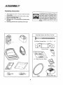
Unpacking
instructions
t,
Remove
box from
shown below,
2o
Cut down four corners of the carton
knife
and fold down sides,,
Remove
mower
deck from skid_
3.
4.
5.
carton..
The box contains
with
The operation
of any tractor can result in
foreign objects thrown into the eyes, which
can result in severe eye damage
Always
wear safety glasses or eye shields before
starting your tractor and while mowing
We
recommend
Wide Vision Safety Mask for
over the spectacles
or standard
safety
glasses, available at Sears Retail or Catalog
Stores,
the items
a utility
Shift tractor into "N" neutral position and release park.
ing brake
Carefully guide the tractor backwards off the skid.
Parts
Bag
]_""_
Contents
::
Not
Shown
Full
Size:
ilflf"lti'ltlli[tl"l't')_tlililt!l{'H"l'!l
!ltjl'j{ Hjtl ll fl
(2) Battery Carriage Bolts - I/4 - 20 x 7 - 7/2
Terminal
Guard
{21 Keys
a..
15 o Slope Instruction
Sheet
Battery Caps
And Instructions
a_ seat
b, steering
c, battery
wheat
d,, battery acid
e,. owner's manual
f,, parts bag
V-Belt
5
Steering
Wheel
Cap
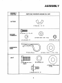
ASSEMBL Y
ASSEMBLY
LOCATION
PARTS
BAG
CONTENTS
SHOWN
FULL
SIZE
BATTER Y
(2) Wing Nut - 1/4 - 20
(2) Hex Bolt,
G
1/4 - 20 x 3/4
BATTERY
TERMINALS
(2) Washer
{2) Lockwasher
9/32
x 5/8 x 16 Ga°
1/4
@
(2) Hex Nut,
1/4 - 20
SUSPENSION
ARMS
(4) Spring
Retainer
'
(4) Washer
17/32
x 1 - 1/16 x 13 Ga.
SEA T
(J) Lockwasher
(1) Hex Bolt, 1/2- 13 x 1
Grade5
1/2
(1) Washer 17/32 x 1-3/16
x 12 Ga.
tlJ Shoulder
6
bolt 5/16
- 18
ASSEMBL Y
To assemble and adjust your tractor you will need:
(2) 1/2" wrenches
Tire Pressure Gauge
Screwdriver
Utility Knife
(2) 7/t6"
wrenches
(1) 3/4"" wrench
(2) 9/16" wrench
d
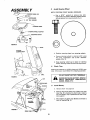
Place seat in operating
position
Sit on the seat and
press clutch/brake
pedal all the way down /f operating position
is not comfortable,
adjust seat
e
To adjust
Raise
seat to desired
securely
NOTE: RIGHT HAND (R.H,) AND LEFT HAND (L.H.) ARE
DETERMINED FROM OPERATOR'S
POSITION WHILE
SEATED ON THE TRACTOR.
WEAR EYE AND FACE SHIELD.
WASH HANDS OR CLOTHING IMMEDIATELY IF ACCIDENTALLY tN CONTACT
WITH BATTERY ACID.
DO NOT SMOKE, FUMES FROM
CHARGED BATTERY ACID ARE EXPLOSIVE.
seat, Loosen adjustment
bolt
position
Tighten
adjustment
CUTAWAYVIEW
___...................
_-VENT
LIQUID
LEVEL
BATTERY
CELL
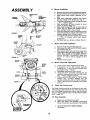
Prepare Battery
READ
CAP
BATTERY
TUBE
NOTE: THIS TRACTOR
IS EQUIPPED
WITH AN
OPERATOR PRESENCE SENSING SWITCH, ANY ATTEMPT BY THE OPERATOR TO LEAVE THE SEAT WITH
THE ENGINE RUNNING AND ATTACHMENT
CLUTCH
ENGAGED WILL SHUT OFF THE ENGINE°
1.
Slide
bolt
FIGURE
INSTRUCTIONS
INCLUDED
I
WITH
OF PARTS, ALWAYS
WEAR GLOVES,
THE
BATTERY
VENT
CAPS FOUND
IN BAG
CLOTHING
AND
GOGGLES
TO PROTECT
YOUR HANDS, SKIN AND EYES,,
andc aitery
b,
c,
d,,
e,
2.
berore
in talling).,
NbTE'SEE
"
DETAILED INSTRUCTIONS PACKAGED WITH BATTERY VENT CAPS IN BAG OF PARTSFill battery with battery acid to bottoms of tubes in cells
(Fig. I) NOTE:' DO NOT OVERFILL OVERFILLING
WILL RESULT tN DAMAGE TO TRACTOR.
Check level of battery acid after 30 minutes. Add addi.
tional battery acid if necessaryr, NOTE: TIGHTEN VENT
CAPS SECURELY,,
SEAT
SHOULDERBO_
DJUSTMENT
It is recommended, that the battery, be charged
betor use. Charge oattery at a rate of six amperes
for one hour.
Neutralize excess battery acid for disposal by adding #
to four inches of water in a five ga!lon plastic container,
Stirwith a wooden or plastic paddle while adding baking
soda until the addition of more soda causes no more
foaming°
=UEL
CAP
Install Seat
/
Seat position should be adjusted forward or backward
so that
the operator can comfortably reach Clutch/Brake
Pedal and
safely operate the tractor (Fig. 2J.
a
b.
co
CLUTCH!BRAKE
Place Seat on Seat Pan° Screw Adjustment Bolt, Flat
Washer and Lockwasher, and ShoulderBolt into Seat(Figo
oAdjustment Bolt, Washers, and Shoulder Bolt Found
Bag of Parts.,,
PEDAL
FIGURE
2
I - MACH,NE
ScREW-'oCKWASHER*
!
T
TightenShoulderBoltusinga
1/2"wrench_Notethatthe
Shoulder Bolt witl be loose in the Seat Pan sloL
Tighten hex bolt (adjustment bolt), lockwasher and flat
washer using a 3/4" wrench.
I
WASHER MUST SE TIGHTENED SECURELY TO PREVENT MOVEMENT
OF SEAT
l ..........................
7
i
, .............
I
Y
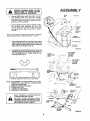
3.
Install
Steering
NOTE: POSITION
STEERING
WHEEL
Wheel
FRONT WHEELS
FORWARD.
CAP
a.
Use a 9/16"" wrench to remove hex bolt,
Iockwasher and 2-3/8" diameter washer (shown
full size below) hom steering shaft (Fig 3)
2 - 3/8" DIA, WASHER
,,.,_,----
STEERING
EERING
WHEEL
WHEEL
ADAPTER
©
FIGURE 3
HOOD
BATTERY
COMPARTMENT
b ,. Position
4.
steering
wheel
over steering
adaptor.
c,
Secure steering wheel
hex bnlt, tockwasher
washer (Fig 3L
d,
Snap steering
wheel cap in place on steering
wheel,, Steering wheel cap found in bag of partso
Check
to steering shaft using
and 2-3/8"
diameter
Tires
Reduce tire pressure to 14 PSI in front and 10 PSI in rear
tires, (Tires were overinflated
for shipping purposes),
GFIILL
DO NOT SHORT
BATTERY
TERMINALS,
FIGURE 4
BEFORE INSTALLING BATTERY, REMOVE
METAL
BRACELETS,
WRISTWATCH
BANDS, RINGS, ETC.
NUT
LOCKWASHER
5o Install Battery
WASHER
a_
Remove
hood
- See page
23
LOCKWASHER
b. Remove tape from plastic tray, Make sure drain
tube (Fig. 5) is fastened to drain hole in battery
tray and battery tray is positioned in hole of battery support.
HEX
BOLTS
c , Place battery in plastic tray (Battery terminals to
front of tractor)(Fig=
5),
BLACK
(NEGATIVE)
CABLE
FIGURE
5
DRAIN TUBE
8
ASSEMBL Y
NECTED
TO PREVENT
SPARKS
POSITIVE FIRST
TERMINAL
MUST
BE
CONFROM ACCIDENTAL GROUNDING,
do
e.
Connect RED battery cable to positive (+) battery
terminal
with hex bolt,
flat
washer,
iockwasher and hex nut (shown full size on page
6) found in bag of parts (Fig. 6}. Tighten securely
with two 7/16" wrenches°
WING
NUT
/
WING
NUT
,t'
/
Cor}nect
BLACK ground cable to negative
(-) bat- ._.
tery
terminal
with
remaining
hex
bolt,
flat
washer,
Iockwasher
and hex nut (shown
full size
on page
securely.
6) found
in bag, of parts
(Fig
6)
Tighten
NOTE: tF YOU HAVE A WEAK BATTERY,
SEE "STARTING
_fOUR TRACTOR
WITH A WEAK BATTERY"
PAGE 19
f_
Using the square hole on one side of the battery
support (Fig. 6) insert one battery bolt, head of bolt
down. Fasten the battery bolt to the terminal guard
using wing nut as shown in (Fig. 6)_
FIGURE 6
g_
Assemble the remaining battery bolt to other side
of battery support and fasten tern'final guard to it
with remaining wing nut,, Tighten wing nuts securely by hand (Fig,, 6)°
HEIGHT
ADJUSTMENT
KNOB
.... > ;+_,'
-I:"_'_
ATTACHMENT
LiFT LEVER
"'HIGHEST"
POSITION
LIFT
LEVER
ATTACHMENT
_,p._
MOWER
Z3
73
h+ Remove
Plastic
on tractor
hood
.
-,,,_
j
ARM
MOWER
BRACKET
J \'tJ
and close
NOTE: USE TERMINAL ACCESS DOORS (FIG. 6) FOR:
1o INSPECTION
FOR SECURE
CONNECTIONS
(TIGHTEN HARDWARE)
2. INSPECTION FOR CORROSION
3o TESTING BATTERY
4o JUMPING (IF REQUIRED)
5. CHARGING (IF REQUIRED)
RELEASE
PiN
,,..,,.
FRONT
SUSPENSION
BRACKET
FIGURE
7
FIGURE
8
KEEP TERMINAL
ACCESS" DOORS
CLOSED WHEN NOT IN USE.
DO NOT
START
ENGINE
UNTIL
MOWER SUSPENSION
BRACKET HAS
BEEN-RELEASED.
SEE MOWER DRIVE
BELT INSTALLATION,
PAGE 10,,
SPRING
9
A
Y
MOWER
6o
_
Installation
ao Remove band from mower suspension bracket,
b_ Remove banding from suspension arms (Fig. 7),
c_ Slide mower under tractor, deflector to R_H.
side°
d._ Slide front suspension brackets into mower
brackets° Retain with release pins (Fig° 7)_
e o Turn depth adjustment knob counterclockwise
( _
) until it stops_
f,
Push attachment
rift lever forward
to lower
mower to ground (page 11).,
g, Slide studs through lift links on both sides of
tractor (Fig. 8)° Retain with washers and retainer springs found in bag of parts.
h • Place the suspension arms on brackets on both
sides of frame (Fig. 8). Retain with washers and
retainer springs found in bag of parts.
i,
Turn height adjustment
knob (Fig. 7) clockwise
(
_
) to remove
slack
from
mower
suspension,
j ,. Roll drive belt over primary mandrel (Fig_ 9)°
DRIVE
FIGURE 9
WHEEL
GAUGE/
BAR
Mower
ETAINER
SPRING
GAUGE
WHEEL
7.
Mower
Drive Belt Installation
BRACKET
a
b
/
FIGURE
CLEVIS
10/PIN
d_
CLUTCH
PULLEY
8,
MOWER
DRIVE
BELT
Mower
Drive
Belt Adjustment
a,
b,
Lower mower using attachment
lift lever.
If dimension
-A" on idler bracket assembly
measures 1/4" or less, mower drive belt must
be adjusted (Fig_ 1 l-Inset).
c, Disengage attachment
clutch switch_
d. Using two 9/t6"'
wrenches,
remove bolt, (2)
washers, lock washer and nut from idler pulley
(Fig_ 1 t-Inset) (original position),
e
Place v-belt and idler pulley #1 'WEW" pulley
position
(Fig_ 11-Inset).
Replace bolt,
(2)
washers, Iockwasher and nut. Tighten securely,
f _ Check v-belt for properinstallation
on all pulley
grooves°
IDLER
PULLEY
TENSION
PULLEY
FIGURE
Remove hood and grill (See page 23),
Pull mower drive belt over front mower suspension bracket (Fig. 9)_
Place mower drive belt over clutch pulley and
under idler pulley and tension pulley (Fig. 1 I).
NOTE: PULL LEVER UP TO SWING TENSION
PULLEY FOR BELT CLEARANCE,
Make sure
narrow
"'V'" side of belt is engaged in each
pulley,. _
Replace hood and grill
11
9.
Check the Cutting Level
The blade housing was set at the factory to cut level°
After mowing a short distance, look at the area that was
cut.. if the blade housing cuts uneven; see the instructions on "Side-to-Side
And Front-to Rear Mower Adjustmen/'" (page 24)"_
10. Final Assembly
a ,, Make sure aft fasteners are tight_
b. Read and follow the operation instructions
Know the location and purpose of aft controls.
c_
10
Check oil and gasoline before starting
the tractor_
OPERA TI ON
KNOW
YOUR TRACTOR
READ THIS OWNER'S MANUAL BEFORE OPERATING YOUR GARDEN TRACTOR_ If you understand the machine and
its operation, you will achieve efficient and peak performance,
While reading the manual, compare the illustrations with
Your Garden Tractor to familiarize yourself with the location of various controls and adjustments. Study the operating
instructions and safety precautions
thoroughly
to insure proper functioning of your Garden Tractor and to prevent injury to yourself and others, Be sure to pay strict attention to all notes and cautions; they are included for your safety.
Save this manual for future reference.
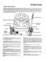
Control
Attachment
Clutch
Switch
Attachment
Ammeter
Clutch/Brake
Lift Lever
Pedal
Switch
Ignition
Choke
I
,_
Height
Adjustment
Knob
Gear Shift
................
Lever
!
Parking
Brake
Shift
Lever
AMMETER: Each time you start your tractor, check your
ammeter.
The needle should move towards
the I + )
charging mark indicating
the battery is being charged as
you operate the tractor, The headlights will not show a
discharge on the ammeter
because they are not connected to the battery
(they have their own electrical
$our_e),
ATTACHMENT
CLUTCH SWITCH: Pull switch out and
up to engage attachment,
There will be an engine hesita _
t/on as the clutch engages.
ATTACHMENT
LiFT LEVER: Use the attachment rift lever
to raise and lower the attachment
mounted to your tractor, Move the lift lever forward to lower attachment.
CHOKE: To start a cold engine, pull choke out to engage,
LIGHT SWITCH:
CLUTCH/BRAKE
PEDAL: The pedal has 2 functions: a
clutch and a brake,. To engage push the pedal cornp/etely down.
PARKING BRAKE LOCK: To set the parking brake, push
the clutch/brake
pedal completely
forward° Place the
parking brake lever in "Engaged"
position and release
pressure from pedal., Clutch/brake
pedal will remain in
brake position,
HEIGHT ADJUSTMENT
KNOB: Use the height adjustment knob to adjust the mower height. With attachment
rift lever in the furl "'UP" position, turn clockwise (_)
to raise mower end counterclockwise
(4"-_) to lower
mower,
GEARSHIFT: Press the c/utch/brake pedal down firmly
and move gear shift lever to desired speed.
IGNITION:
start.
Turns
on and off the headlights
RANGE SHIFT LEVER: The HioLo range shift lever gives
you the versatility of 6 speed selections: Lo 1, 2, 3, and
Hii,
2,3.
THROTTLE CONTROL: Use the throttle control to in.
crease or decrease the speed of the engine.
Place key in ignition and turn to the right to
11
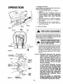
OPERA TI ON
1. Stopping
Your Tractor
NOTE: REMOVE KEY WHEN LEAVING
PREVENT UNAUTHORIZED
USE,
TRACTOR
TO
a. Push clutch/brake pedal into furl "'BRAKE'"
position.
b. Place parking brake in "ENGAGED"
position and
release pressure from clutch/brake. Pedal should
remain in "BRAKE" position. NOTE: MAKE SURE
PARKING
BRAKE
WiLL
HOLD
TRACTOR
SECURE_
c. Move gear shift lever to "NEUTRAL'"
position_
d_=Place attachment clutch switch in "DISENGAGED'" position_
e. Move throttle control to "'S" (slow) position°
f_ Turn ignition key to "OFF" position.
Never use
choke to stop engine,
DIPSTICK
ENGINE
2.
Starting
The Engine
FIGURE 12
SEAT
SEAT
PAN
IIW|TCH
1
HAT
LEARN TO START, STOP AND REVERSE I
YOUR TRACTOR IN A LARGE, OPEN AREA_
J
NOTE: THIS TRACTOR IS EQUIPPED WITH INTERLOCK
SWITCHES TO PREVENT STARTING OF THE TRACTOR
ENGINE WHILE THE ATTACHMENT
CLUTCH OR THE
CLUTCHIBRAKE
PEDAL IS ENGAGED,
IMMEDIATELY REPLACE SWITCHES THAT
ARE NOT IN PROPER WORKING ORDER,
DO NOT ATTEMPT TO DEFEAT THE PURPOSE OF THESE SWITCHES,
\
CLUTCH
BRAKE/PEDAL
FUEL
/
FIGURE
a.
TANK
\
CAP
13
ATTACHMENT
CLUT(
CHOKE
THROTTLE
KEY
CAUTION: EXPERIENCE INDICATES THAT ALCOHOL
BLENDED FUELS (CALLED GASOHOL OR
USING ETHANOL OR METHANOL) CAN ATTRACT MOISTURE
WHICH LEADS TO
SEPARATION AND FORMATION OF ACIDS
DURING STORAGE.
ACIDIC GAS CAN
DAMAGE THE FUEL SYSTEM OF AN ENGINE
WHILE IN STORAGE.
HEIGHT
ADJUSTMENT'
KNOB
TO AVOID ENGINE PROBLEMS, THE FUEL
SYSTEM SHOULD BE EMPTIED BEFORE
STORAGE FOR 30 DAYS OR LONGER. DRAIN
THE GAS TANK, START THE ENGINE AND
LET IT RUN UNTIL THE .FUEL LINES AND
CARBURETOR ARE EMPTY. USE FRESH
FUEL NEXT SEASON. SEE STORAGE INSTRUCTIONS
FOR ADI_ITIONAL INFORMATION (PAGE 26)°
PARKING
BRAKE
RANGE
LEVER
FIGURE
14
This engine has been shipped filled with summer
weight oil (for cold weather operation see Chart
page t6)_ Check engine oil level with tractor on
level ground. Wipe dipstick (Fig. 12) clean, screw
it in tight for a few seconds, remove and read oil
level If necessary, add oil until "'FULL'" mark is
reached,
NEVER USE ENGINE OR CARBURETOR
CLEANER PRODUCTS IN THE FUEL TANK
OR PERMANENT DAMAGE MAY OCCUR.
GEAR SHIFT
CONTROL LEVER
12
TION
b. Fill fuel tank "(Fig,, 13). Use fresh, clean, regular
unleaded automotive
gasoline.
(Use of leaded
gasoline
will increase carbon and lead oxide
deposits and reduce valve life)o Capacity is 3-1/2
gallons.,
co Place attachment
clutch switch in "'DISENGAGED'" position.
do Push clutch/brake pedal fully into brake position_
e o Place gear shift lever in "'N'" neutral, start position (Fig. 14).
f o Place range shift lever in "'N" neutral position (Fig,
14)_
go Pull choke out {Fig
DO NOT OPERATE THE MOWER WITHOUT
EITHER THE ENTIRE GRASS CATCHER,
ON UNITS SO EQUIPPED, OR THE DEFLECTOR GUARD IN PLACE.
CAUTION
t4)_
h _ Move throttle control to middle position (Fig, 14)_
i.
j.
: DO NOT ADD ADDITIONAL
WEIGHT
TO THE TRACTOR OTHER THAN THE
OPTIONAL
WHEEL WEIGHTS,
EXCESSIVE WEIGHT MAY OVERLOAD
AND DAMAGE THE TRANSM4SSlON
PLUNGER
ADJUSTMENT
DEPT.
Turn ignition to "START"
position until engine
starts (Fig, 14). NOTE: DO NOT RUN STARTER
CONTINUOUSLY
FOR MORE THAN FIFTEEN
SECONDS PER MINUTE, tf engine does not start
after several attempts, move throttle control to
"'F'" (fast) position, wait a few minutes and try
again_
After engine is warm, push choke in,
ATTACHMENT
LIFT LEVER
The first time you start the engine, it will take extra
cranking time to move fuel from tank to engine, NOTE:
ALLOW ENGINE TO WARM UP FOR A FEW MINUTES
BEFORE ENGAGING CLUTCHtBRAKE
PEDAL OR ATTACHMENT
CLUTCH SWITCH,
k o When restarting
a warm engine, move throttle
control midway between "'S'" (slow) and "'F'"
(fast) position, Choke may not have to be used.
BEFORE DRIVING THETRACTOR, INSTALL
MOWER OR REMOVE FRONT MOWER SUSPENSION BRACKET AND SUSPENSION
ARMSo(FIG.8)
TO AVOID
GAUGE
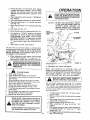
3.
WHEEL _
Operating
CLEVIS
_,*
PIN
FIGURE
I5
Your Tractor and Mower
NOTE: THIS TRACTOR
IS EQUIPPED
WITH
AN
OPERATOR PRESENCE SENSING SWITCH,
ANY ATTEMPT BY THE OPERATOR TO LEAVE THE SEAT WITH
TI;IE ENGINE RUNNING
AND THE ATTACHMENT
CLUTCH ENGAGED WILL SHUT OFF THE ENGINE,
INJURY
!_
24
3.
Read owner's manual
Know location and function of al! controls
Keep guards, safety shield and switches in place
and working,
4,. Remove objects that can be thrown by blades.
5o Do not mow when children and others are around.,
6. Never carry children or passengers,
7. Always look behind machine before backing
8. Do not mow where machine can tip or slip
9. If machine stops going uphill, stop blades and back
slowly down.
10. Be sure blades and engine have stopped before
placing hands or feet near the blades,
11. Remove key when leaving machine.•
L _
BEFORE
OPERATING YOUR MOWER.
READTHE"SAFETYRULES"CAREFULLY
t
Use the height
adjustment
knob (Fig
!4) to adjust
mower height
With the attachment
lift lever in the furl
"UP" position,
turn height adjustment
knob clockwise
('-_) to raise cutting height and counterclockwise
(_-'}
to lower cutting height
Lower attachment
hft lever to
check adjustment
NEVER PLACE YOUR HANDS OR FEET IN
OR UNDER ANY POWERED ATTACHMENT
OR NEAR ANY MOVING
PART WHILE
TRACTOR
OR ANY POWERED ATTACH_
MENT IS RUNNING.
DO NOT OPERATE THE MOWER WITHOUT
THE DEFLECTOR SHIELD IN PLACE
13
a° To adjust gauge wheels (Fig, 15) lower attachment rift lever,
b . Remove retainer spring and clevis pin from gauge
wheels°
c. Move gauge wheels to the adjustment
hole that
will provide the desired cut,,
d,, Replace retainer spring and clevis pin.
e. Move attachment
rift lever to its full "UP"
position.
f o With engine running and warm, place throttle con_
trol midway between "'S" (slow) and "F'" (fast)
position (Fig° 14)oo.
g. To engage mower puff attachment
clutch switch
(Fig. 14) out and up.
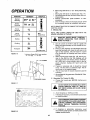
OPERA TION
FUNCTION
GEARSHIFT
Normal
Mowing
2H*
Heavy
Mowing
1H or 2L
Snow
Removal
1L
Tilling
Plowing
1L
Do i°g
1L
Grading
2L
h ,, Move range shift lever to "'LO" (low) postion (Fig_
14L
i. Move gear shift lever to desired gear (Fig 14L
jr Use attachment lift lever to lower mower into cutting position,
k,. Release clutch/brake
pedal SLOWLY
to start
movement,
I, Start mowing at slow and increase ground speed
by increasing throttle as conditions
will permtt,
THROTTLE
or 3L*
NOTE: BRING TRACTOR
SHIFTING GEARS
4.
FAST
Mowing
TO COMPLETE
Tips
NOTE: TIRE CHAINS CANNOT
MOWER HOUSING ATTACHED
MID
THROTTLE
STOP BEFORE
BE USED WITH
THE
L.....
:_
,,,,,,,,
BEFORE OPERATING
YOUR
MOWER,
READ THE "SAFETY RULES" CAREFULLY
REFER TO PAGE 2o
a_ Use the runner on the R,H, side as a guide; the
blade cuts approximately
an inch outside the runner (Fig_ t 7).
b, Drive so that clippings are discharged onto the
area that has been cutu Have the cut area to the
right of the machine,
This will result in a more
even distribution of clippings and more uniform
cutting_
c, When mowing large areas (Fig. 18), start by turning to the right so that the clippings
will be
discharged away from shrubs, fences, driveways,
etc. After two or three rounds, mow in the opposite direction
making
left hand turns until
finished.
d, If grass is extremely
tall, it should be mowed
twice. The first time cut relatively high_ The second time to the desired height,,
e, The left hand side of mower should be used for
trimming,
=
3H
Transport
SLOW-FAST
FIGURE
16
" Indicates
Range Shift Lever position:
"'H" for High "'L" for low
RH,
RUNNER
f,, DO not mow tall, dry grass over 6 inches talL It is a
fire hazard
DISCHARGE
FIGURE
5,
GUARD
Operating The Tractor On Hills
a. Choose the lowest gear BEFORE starting
do wn hills_
up or
17
DO NOT DRIVE UP OR DOWN HILLS WITH
SLOPES GREATER THAN 15 ° AND DO
NOT DRIVE ACROSS ANY SLOPE, REFER
TO PAGE 51,
%
i-_
Jtr
b=, Avoid ,stopping or shifting on hills.
c ,. If slowing is necessary, move throttle
to middle position,,
X
f
....
lIT.'._
t
"
LEAVE ENOUGH ROOM WHEN STOPPING
AND STARTING TO ALLOW SLIGHT TRACTOR ROLL DOWNHILL AS CLUTCH/BRAKE
PEDAL
MOVES
THROUGH
CLUTCH
.................................
POSITION.
J
FIGURE
control lever
d, tf stopping
is absolutely
necessary,
push
clutch/brake
pedal quickly to brake pbsition and
engage parking brake,
18
14
l
e,
To restart your tractor, make sure tractor is in 7st
gear and that you have allowed room to roll slightly downhill. Disengage parking brake and release
clutch/brake pedal SLOWLY to start tractor forward movement°
f.
Make all turns slowly°
INTENANCE
To keep
your tractor
running
better,
longer, perform necessary
service using
the following
maintenance
schedule:
BEFORE MAKING ANY INSPECTION,
ADJUSTMENT
OR REPAIR: (FIG. 19):
!, PUSH TRACTOR CLUTCH/BRAKE
PEDAL COMPLETELY INTO BRAKE
POSITION.
2o MOVE
GEAR SHIFT CONTROL
LEVER TO NEUTRAL POSTION.
3_ PLACE
PARKING
BRAKE
IN
"ENGAGED"
POSITION .AND REMOVE FOOT FROM PEDAL.
4, TURN
OFF
ATTACHMENT
FIGURE
5o CLUTCH
SHUT OFFSWITCH°
THE ENGINE,
6o MAKE ABSOLUTELY
SURE THE
BLADES AND ALL MOVING PARTS
HAVE COMPLETELY STOPPED.
7. DISCONNECT
THE SPARK PLUG
WIRES FROM THE SPARK PLUGS
AND KEEP WIRES AWAY FROM
THE SPARK PLUGS TO PREVENT
INJURY
FROM
ACCIDENTAL
STARTING.
BE CAREFUL
TO
AVOID TOUCHING
HOT ENGINE
OR MUFFLER COMPONENTS,
With
/
LH
ENGINE OIL
DIPSTICK
AND FILL TUBE
Every Mowing
19
SIDE
/
Io Make sure all nuts on bolts are tight and cotter pins
and retainer springs are secure,
2.
Observe
a!l safety
3,
Keep tractor
precautions
well lubricated
First 2 Hours (Two
/
(refer to page
18),
Mowings)
1o Change Engine Oil
Changing off after the first two hours (or two mowings) will help eliminate break-in residue which might
be damaging to your engine.
NOTE: BE CAREFUL NOT TO ALLOW DIRT TO ENTER
THE ENGINE WHEN (_HANGING OIL.
FIGURE
a,, Drain oil with engine warm.,
b .. Remove hood and grill (see page 23)_
co Loosen oil drain wing nut (Fig, 20 - Inset),
Catch oil in a suitable container.
d. Tighten oil drain wing nut after all oil has been
removed from engine°
eo Refill engine oil., Refill capacity is 3 pints.
NOTE: DO NOT OVERFILL.
f o Replace dipstick.
15
20
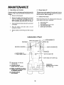
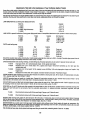
MAINTENANCE
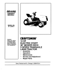
Recommended
SAE
Viscosity
Grades
Determine temperature expected before next oil change,
All oil must meet A_PJ_ service classification SD, SE or
SF.
60 °
80 °
100 °
0o
32 °
SHIFT
COVER
, ,,,.,.,
Ill .......
lily, k,
30 or 10W-30
\
Capacity is 3 pints, NOTE: DO NOT OVERFILL. Dipstick
assembly must be securely tightened
into tube at atl
times when eng/ne is operating,
o
CAUTION:
FIGURE
TO AVOID DAMAGE TO THE STARTING SYSTEM, USE SAE 5W30 OIL
WHEN THE TEMPERATURE
FALLS
BELOW 32°_
21
Every
5 Hours
(Five
Mowings)
1. Check Engine Oil Level
NOTE:
D
DO NOT CHECK ENGINE
WITH ENGINE RUNNING.
OIL LEVEL
Several minutes after stopping engine, check engine oil
level with tractor on level ground. Wipe dipstick (Fig, 20)
clean, screw it down tight for a few seconds, remove
and read oil level. If necessary, add oil until "FULL ""mark
is reached. NOTE: DO NOT OVERFILL
Every
FIGURE 22
25 Hours
(Twice
a Mowing
Season)
(Operating in dusty conditions may require more frequent
servicing3
1o Brake Adjustment
IF TRACTOR
t
..... 1
t
\
FIGURE
MORE THAN
HIGHEST
SIX
FEET GEAR
STOPPING
ON ADISTANCE
LEVEL DRY
IN
CONCRETE
OR PAVED
SURFACE
THEN BRAKE MUST BE ADJUSTED.
t
BLADE
REQUIRES
!
a. Remove (4) hex washer head tapping screws from
shift cover plate (Fig° 21), located on top of tractor frame. Remove the cover plate,
I
b.
Loosen jam nut (G) on brake rod (B) at clevis (c)
(Fig. 22). If you find it difficult to loosen jam nut
(G), remove cover plate in LoHo frame tail.
c, Rotate brake rod (B) counterclockwise
(V"_) turning brake rod out of clevis (C) four to six turns.
d. Start tractor with tramsmission
in 'W" (neutral)
position.
23
e_ Depress clutch/brake
stops moving.
16
pedal to the point where belt
f . Engage parking brake to hold clutch/brake pedal
in position° If belt begins to move after engaging
parking brake, depress clutch/brake
pedal to next
notch on parking brake,
CUT AWAY VIEW
g, Shut engine off. Rotate brake rod (B) clockwise
(('_) by hand, turning brake rod into clevis (C),
until tight° Tighten jam nut (G) on brake rod. (B)
at clevis (C) (Fig, 22)°
LIQUID
LEVEL
BATTERY
TUBE
h, Reinstafl shift cover plate and four (4) mounting
screws, Replace cover plate if removed in step b.
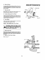
2.
BATTERY
CELL
Tire Care
Maintain tire pressure
at 10 PSI,
3o
in front at 14 PSI and rear tires
FIGURE 24
Blade Care
KNOB
For best results mower blades must be kept sharp° The
blades can be sharpened with a few strokes of a file or on
a grinding wheel We suggest they be sharpened after
every24 hours of mowing. Do not attempt to sharpen while
on mower, ff you mow in sandy soil check the blades after
each two reDwings. The sand wears the blades away
rapidly,
a.
b,
COVER
NUT
WASHER
CARTRIDGE
PLATE
When grinding, care should be taken to maintain blade balance and the blade should be
checked for proper balance before reinstallation
on mower.
Unbalanced or bent blade will cause excessive
vibration when running and eventual damage to
mower
or engine, Replace bent or damaged
blades,
PAPER
CARTRIDGE
OIL FOAM
PRE-CLEANER
TO check blade balance, drive a nail into a beam or wafl.
Leave about one inch of the straight nail exposed° Place
center hole of clean blade over the head of the nail (Fig.
23), NOTE: CENTER HOLE OF BLADE ON NAIL.. tF
BLADE tS PROPERLY BALANCED, BLADE SHOULD REMAIN IN POSITION SHOWN tN F1G. 23. IF EITHER END
OF THE BLADE MOVES DOWNWARD,
BLADE IS NOT
BALANCED,
SHARPEN THE HEAVY END UNTIL THE
BLADE IS BALANCED.
Every
50
(Operating
servicing)
1,
Hours
(Once
a Mowing
in dusty conditions
BODY
FIGURE 25
2_
Clean A# Filter
a.
Unscrew
b,
Remove nut and washer to remove cartridge
plate, paper cartridge and oil foam pre-cleaner
Season)
may require more frequent
b o Keep battery and terminals
t8,
d
than twist)
go
c_
Keep battery
bolts
d,
Keep vent caps
caps open.
tight.
tight
and small
Rinse, squeeze
throughly,
vent holes in
17
(rather
cover
and water,
allow
to dry
Lightly
coat with S A E 30 engine oil Do not
saturate
Squeeze in a rag or towel to distribute
evenly and remove excess
f o Check
dirty,
clean. Refer to page
25) to remove
in detergent
e,
Battery ac_ solution level in each battery cell shouldbe
even with t_ottoms of tubes in cells (Fig, 24)_ Add only
distilled water if necessary. NO TE: DO NO TO VERFIL L
DO NOT ADD ACID,
(Fig
c _ Wash foam pre-cleaner
Check Battery
a,
knob
paper
cartridge,
Replace
if excessively
Reassemble paper cartridge and re-position
on
tractor_ NOTE: NEVER RUN ENGINE WITH AIR
FILTER REMOVED
AS DIRT (DUST) WILL
DAMAGE THE ENGINE,
MAINTENANCE
3°
Clean Battery
and Terminals
4.
Corrosionand dirt on the battery and terminals cause the
battery to "leak" power and hindersthe operation of the
charger.
a ,. Remove terminal guard_
The best time to drain engine all is at the end of a day's
operation when all dirt and foreign materials are suspended in the hot oil Refer to page 15o
5,
b_
Remove the battery from the tractor and wash
with four tablespoons of baking soda to on_
gallon of water, NOTE: BE CAREFUL NOT TO
GET THE SODA SOLUTION INTO THE CELLS,
c .. Clean terminals
until bright.
do
plain
water,
Lubricate Pivot Points
Place several drops of S.A.E. 30 oil at points where parts
move against each other, especially:
a,
b,.
c.
d.
eo
and cable ends with a wire brush
Rinse the battery with
reinstall on tractor°
Change Engine Oil
dry and
Front Axle Pivot
Hood Hinges
Foot Pedal Shaft {both ends)
Lift Shaft {both ends)
Secl_x" gear pivot points
e . Replace cables and terminal guard. Refer to page
8.
Lubrication
Chart
HINGES @
SPINDLE @
WHEEL BEARINGS @
®
BOTH
FOOT ENDS
PEDAL OF
SHAFT-
SECTOR GEAR Q
--
BOTH ENDS LIFT SHAFT@
]L_) SAE 30 (SC, SD OR SE)
MOTOR OIL
@
--
CHASSIS GREASE
SEARS PART NO,, 2557R
TRANSAXLE
{CHECK LEVEL AT REAR
FILL PLUG)
REFER TO ENGINE OIL SPEC'S.
(UNDER INITAL PREPARATION
IN OWNERS MANUAL)
CHASSIS
GREASE
WITH BRUSH
18
@
6.
Clean Air Screen
MAINTENANCE
Air screen (Fig. 26) must allow free-flow of air to prevent engine damage from overheating. Clean with a wire
brush or compressed air to remove dirt, stubborn dried
gum and fibers.
7.
MUFFLER
Clean Front Grill
Lubricate
ENGINE
of air,
COOLING
FINS
Steering and Front Wheels
There are four grease fittings on your tractor (Fig° 27).
Using a grease gun, give each grease fitting two shots
of chassis grease (available through your Sears Service
Center). Sears Part No. 2557R_
9.
SHIELD
/
\
Brush debris from front grill to allow free-flow
preventing engine damage from overheating.
8.
I
.,,,,e'_ HEAT
AIR
SCREEN
AIR GUIDE
COVER
Figure 26
Check Muffler
Inspect and replace corroded muffler as it could create
a fire hazard and/or engine damage,
EVERY
100 HOURS
(Every
Two
Years)
DISCONNECT SPARK PLUG WIRES TO PRE-_
VENT
ACCIDENTAL
STARTING
BEFOREMAK_J
ING ANY
INSPECTION,
ADJUSTMENT
OR_
REPAIR (EXCEPT CARBURETOR)_
1.
!
Replace Spark Plugs
Replace spark plugs at the beginning of each season or
every 100 hours,whichever comes firsL Gap shou/dbe set
at 0°030 inch (Fig. 28), Refer to Page 45 for replacement
information.
2.
Replace Air Filter Paper Cartridge
Refer to page 17_
FRONT
AXLE
PIVOT
FRONT SPINDLE
(GREASE FITTING)
|LEFT & RIGHT)
LUBRICATE
THE
STEERING PLATE
IN AREA OF SECTOR
GEAR
WHEEL
GREASE FITTING)
(LEFT & RIGHT)
FIGURE
19
27
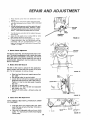
REPAIR AND ADJUSTMENT
1. Starting Your Tractor with a Weak Battery
If your battery is too low to start the engine, it should
be recharged.. If "jumper cables" are used for emergency starting follow this procedure:
NOTE: YOUR TRACTOR IS EQUIPPED WITH A 12 VOLT
NEGATIVE GROUNDED SYSTEM, THE OTHER VEHICLE
MUST ALSO BE A 12 VOLT NEGATIVE GROUNDED
SYSTEM_
FIGURE 28
_'lk
LEAD-ACID BATTERIES GENERATE EXPLOSIVE_
GASES. KEEP SPARKS, FLAME AND SMOKING 4
MATERIALS
AWAY
FROM
BATTERIES.I
ALWAYS WEAR EYE PROTECTION AROUND[
BATTERY.
j
NEGATIVE
(BLACK CABLE)
TERMINAL
a o Connect each end of the RED cable to the
POSITIVE (+) terminals of each battery (taking
care not to short against chassis). (Fig. 29).
b,_ Connect one end of the BLACK cable to the
NEGATIVE (-1 terminal of fully charged battery,
co Connect the other end of the cable to L H, side
panelbolt (Fig. 19). NOTE: KEEP AWAY FROM
GAS TANK AND BATTERY.
do Disconnect cables in reverse order:
1., L_H_ Side Panel Bolt (Fig_ ! 9).
2_ Negative Terminal of fully charged Battery
3. Postive Terminals
BATTERY
CAUTION:
POSITIVE
(RED CABLE)
TERMINAL
FIGURE
2
DO NOT USE YOUR BATTERY
START OTHER VEHICLES.
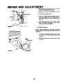
THROTTLE
CONTROL
TO
CABLE ADJUSTMENTS
Never attempt
to change maximum
engine speed This is
preset at the factory (3400
± 100 RPM) and should only
be change by a qualified
service technician who has the
necessary equipment
a
Remove hood page 23
b
Loosen casing clamp screw until throttle cable is free
to move(Fig_ 30).
c
Move throttle control {on the dash board) to "Fast "_
position
d
Pull thro_tle cable tight (until swivel is against side of
quarte_ circte) Fig 30 Retighten casing clamp screw
29
CHOKE
CABLE
REFER TO "STARTING
PAGE
CARBURETOR
THE ENGINE",|
12o
ADJUSTMENT
NOTE: Adjust throttle control cable before making any adjustment
to carburetor
Air cleaner must be assembled to
carburetor
when running engine
Minor carburetor
adjustments
may be required to compensate for differences
in fuel. temperature
or altitude
_djusz
the carburetor
fuel mixture as follows:
a
b
FIGURE 30
2O
Gently turn idle mixture valve clockwise
('"_)
Fig, 31
until it just closes and then counterclockwise
P"-'_)
1 1!2 turns
CAUTION:
Valve may be damaged if turned in too far
Start engine and allow to warm for five minutes
Make
final adjustments
with engine running and choke pushed in
FtEPA
c
d
e
Move throttle
control
leve_ Ion dashboard)
to slow
position
Hold governor control lever against idle speed screw.
and adjust idle speed screw to obtain t 200 to 1400 RPM
Fig
31
Whg slJ_lholding the governor control lever against idle speed
screw, tum idle mixture vaJveslowly clockwise (F_)(lean
mixture) until speed just starts to slow, Then tum counterclockwise (('-"_) (fic_hmixture) until engine begins to run rough
f
Turn idle mixture
rich and lean
g
Adjust the idle speed screw to obtain 900 to 1200
RPM Release governor control lever
Move throttle control (on the dashboard)
to _FAST'"
h
AND ADJUSTMENT
valve
back to the midpoint
between
FIGURE 31
If engine hesitates or dies, turn idle mixture valve approximately
I/8 turn counterclockwise
(Y-'_) until
engine wit! accelerate
"SLOW"
to "FAST"
as throttle
control
/
is moved from
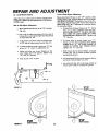
4_ Electric Clutch Adjustment
The electric clutch (Fig° 32) should provide years of service, The clutch incorporates a built-in brake that stops
the pulley almost immediately, Eventually, the internal
brake will wear so the mower blades will not stop as
recommended.
Adjustment
must be made by a Sears
Service Technician,,
5.
Motion
Drive Belt Renloval
The belt on this tractor is special for this application.
Always replace wffh the Sears belt number in the parts
list. It is not necessary to remove mower.
FIGURE
a o Raise hood and disconnect negative ground battery cable°
b. Set parking brake (to get belt slack).
c., Loosen (do not remove) two engine pulley belt
guide bolts and swivel R.H. side of belt guide up.
Tighten LHo bolt to hold belt guide in position
(Fig,, 33).
d,, Roll belt off engine pulley,
e. Roll belt off "'V" idler, flat idler and adjustable
idler pulleys (Fig. 34),
f o Pult belt off clutch pulley - between pulley and
frame.
32
BELT
GUI
LOOSEN
ENGINE
PULLEY
FIGURE 33
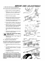
6,
Motion
Drive Belt Replacement
NOTE: THERE IS A BELT INSTALLATION
Loll,, FOOTREST°
DECAL UNDER
a. Push belt down from engine pulley area.. Place
back (flat) side of belt on flat idler. (Flat idler is
next to frame),.
b. Place belt on adjustable idler and over clutch
pulley. "'V" (narrow) part of belt should engage
clutch pulley.,
"'V'"
IDL£R
I
CLUTCH
ADJUSTABLE
PULLEY
IDLER
TRANSAXLE
PULLEY
FIGURE
21
34
AND ADJUSTMENT
c.
Place belt around transaxle pulley. "'V'" part of
belt should engage transaxle pulley_
d, Make sure "'V" part of belt engages "V'" idler°
O
Roll belt over engine pulley,
e.
f.
BELTGUIDE
g,
7.
Loosen L.H. engine pulley belt guide bolt and
swivel belt guide bolt and swivel belt guide onto R, Ho belt. Tighten L.H, and R.Ho belts securely
(Fig. 35)°
Release parking brake. NOTE: WHEN A NEW
BELT HAS BEEN INSTALLED, YOU MUST
CHECK BRAKE ADJUSTMENT,
Idler Bracket
Removal
NOTE: WHEN OPERATING TRACTOR WITHOUT
MOWER, REMOVE IDLER BRACKET FROM FRONT OF
TRACTOR.
a,
IDLER
BRACKET
' LOCKWASHER
NUT
FIGURE36
Pull belt up through idler bracket and out of tractor. Use lever to swing tension pulley for belt
removal
b . Remove Iockwashers and nuts from idler bracket
(Fig° 36).
8. Fu_
ADJUSTMENT
Replacement
(D
Fuse is located under dash to the left of the battery., ff
fuse replacement is necessary, replace with 30 amp
automotive- type plug4n fuse_Fuses can be purchased
at all Sears Service Centers and most retail stores,
9,
Check Transaxle
a_
011 Level
Block up rear axle (Fig. 39)
tractor jack°
b o Remove left rear wheel
C_
d.
10.
securely
or use a
I FIGURE 37
by removing hub bolts°
Remove filler plug (Fig 37) from transaxle.
Oil
level must be even with plug threads. See your Sears
Service Center ff additional oil is required. Replace
filler plug,,
Reposition
TRANSAXLE
PLUG
wheel. Secure
with
WIRE
CONNECTION
_.
,/7 >
hub bolts°
Hood Removal
SCREW
a.
Lifthood° Disconnect
tion (Fig° 38).
headlight
wiring connec-
b. Unscrew one screw at rear of each side panel
(Fig. 38)_
c° Pivot hood and side panel forward
tractor (Fig. 39).
d.
11,
To replace,
Mower
reverse
the above
and rift off
procedure.
Removal
a. Lower
mower.,
b,
Puff the four 14) release pins out of suspension
brackets
(Fig. 40).
C.
Puff tJack on attachment
place.
d_
Slide mower forward
primary mandrel.
e. Slide
FIGURE 3B
mower
out from
lift lever and lock into
and remove
belt
from
under tractor.
ATTACHMENT
HANDLE
NOTE: IF AN ATTACHMENT OTHER THAN THE
MOWER DECK IS TO BE MOUNTED ON THE
TRACTOR, REMOVE THE LH. AND R;H. SUS _
PENTION ARMS AND THE FRONT SUSPENTION BRACKET° (FIG,, 40)
!
U_I=ENSIONARM
SUSPENSION'
BRACKETS
RELF_SE.
PIN
- SUSPENSION
- RELEASE
Pm
AND ADJUSTMENT
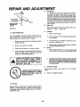
12.
Level Mower
Front to Rear Mower
Housing
Move attachment rift lever to full "UP" position. After
leveling side to side, measure Bottom of Curl at FRONT
AND REAR OF MOWER. The bottom of curl at the R.H.
front flanges should measure 3/4" lower than at the R.H.
REAR flange (Fig° 42Z If adjustment is required follow
the procedure betow,_
Adjust the mower while tractor is parked on level ground
or driveway. Make sure tire pressures are 14 PSI in front;
10 PSI in rear.
Side to Side Mower
Adjustment
a. Move attachment
(Fig. 44).
rift lever to full "UP"
a ,, To raise front of mower loosen nuts "D'. Screw
nuts "'C'" up onto suspension arms (Fig. 43 )_
NOTE: SCREW NUTS "C" ON BOTH SUSPENSION ARMS THE SAME NUMBER OF TURNS
SO MOWER WiLL REMAIN LEVEL Tighten nuts
"'D'" securely_
position
b ,. Use a ruler to make sure bottom of curl at rear of
mower deck is the same height from the ground
on each side (Fig. 42)°
C_
d.
e,
f.
b_
If adjustment is required, snap out access cover
on L,,H. side of tractor above footrest (Fig. 41)o
To raise left side of mower, loosen nut "'B'" and
screw nut "'A'" down on adjustment
rod.
Adjust until both rear mower
flanges are the
same height above the ground, Tighten nuts
"'A'" and "'B'" securety,_
C_
Snap access cover
d_
in ptace_
e,
NUT
Adjustment
To lower front of mower loosen nuts "'C'"
Screw nuts "'D" down suspension arms. NOTE:
SCREW NUTS "D"
THE SAME NUMBER OF
TURNS SO MOWER
WILL REMAIN LEVEL
Tighten nuts "'C'" securely,
With mower deck at desired height, set gauge
wheels (Fi9 44) to lowest
position without
touching the ground,
Use attachment rift lever to set mower at the approximate cutting height you need,
Use clevis pin (Fig. 44 ) to set gauge wheels
lowest point without touching the ground.
"'A"
©
0
FIGURE
NUT
"B'"
41
OF CURL
(REARFLANGES)
FIGtlRE 42
24
at
ADJUSTMENT
13. Blade Drive Belt Removal and Replacement
BELT ROUTING
0
DECAL UNDER MOWER DECK COVER.
a, Remove mower
from tractor
(see page 23).
b,
Remove
top cover
self
tapping
screws,
Iockwashers
and nuts from idler arm bolt.
c.
Ro!! belt over the top of'the
d.
Pull belt off all other mandrels,
R.H. mandrel,
e, Remove any dirt and grass which may have accumulated around mandrels and idler arm,
f.
Check deck idler arm assembly and flat idler to
see that they rotate freely (Fig° 45)
NUT
g.
SUSPENSION
ARMS
°'D"
Be sure spring is hooked in deck idler arm
assembly and on bolt in mower housing (Fig_45).
h, Install new belt in groove
of L,H. mandrel
sheave, lower groove of center mandrel sheave
and around flat idler as shown (Fig. 45).,
i
From a position at discharge end of mower, roll
belt into groove of RH. mandrel sheave (Fig,
45),
j.
Rotate center mandrel sheave by hand to make
sure belt is in grooves properly_
MANDREL
SHEAVES,,
BLADES WILL
ROTATE
t _
14.
k,
Reassemble
top
screws securely_
I
Install mower
Attachment
cover
to tractor
to
WITH
deck.
(see page
RETAINER
SPRING
CENTER
Tighten
GAUGE
WHEEL
aft
10),
IDLER ARM
_
FLAT IDLER
L.H, MANDREL
\
SHEAVE
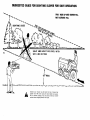
Due to different weights of attachments,
the attchment
lift spring may require adjustment.
The adjustment bolt
is located on rear of tractor top left side (Fig 46).
a, Holding spring bushing with wrench,
nuts,
b,
c.
CENTRAL
MANDREL
NUT
Lift Spring Adjustment
SHEAVE
//
/
R.H, MANDREL
SHEAVE
loosen jam
Turn adjustment bolt clockwise {:'-_) to extend
spring
and reduce
lift effort
(for heavier
attachments),
Turn adjustment bolt counterclockwise
{for lighter attachments).
J
FIGURE
SPRING
BUSHING
UV-_)
•/ATTACHMEN"I
SPRING
d. Retighten jam nut against spring bushing,
NOTE: DO NO,,T ADJUST FOR MAXIMUM SPRING
TENSION WHEN USING LIGHT ATTACHMENTS SUCH
AS A MOWER. ADJUST LIFT LEVER SPRING TO AID IN
LIFTING ATTACHMENT. DO NOT OVERPOWER
SPRING,. WHEN REMOVING ATTACHMENT, ALWAYS
ADJUST WITH SPRING TENSION TO ITS LOWEST
POSITION.
45
25
JAM NUT
FIGURE 46
AND ADJUSTMENT
A.
Fuel System
it is important to prevent gum deposits from forming
in essential fuel system parts such as the carburetor,
fuel filter, fuel hose, or tank during storage A/so,
experience indicates that alcohol blended fuels (ca/led
gasoho/ or using ethanol or methanol) can attract mois*
ture which leads to separation and formation of acids
during storage, Acidic gas can damage the fuel system
of an engine whi/e in storage_ To avoid engine ptoblems,
the fuel system shou/d be emptied before storage of 30
days or longer:
B.
Engine Oil
FLAT WASHER
LOCKWASHER---_(_
HE)( HEAD HEAT --_1
TREATEDBOLT
GRACE 5
Drain (with engine warm) and replace with clean
engine oil, ( Refer t6 page 16).
FIGURE 47
C,
15o Blade Replacement
Cylinders
1_ Remove spark plugs°
it is not necessary to remove mower from tractor for
blade replacement,
Moving adjustment lift lever to up
(Rear) position wilt permit access to blades_
2 _ Pour one ounce of oil through spark plug holes
into cylinders°
a = Remove the hex head bont, tockwasher and flat
washer (Fig, 47L
3o
Turn ignition key to "START"position
seconds to distribute oil.
b_
Remove and discard old btade.
4.
Replace with new Spark P/ugs_ Refer to Page 45
for replacement information,
c.
Clean top and bottom of mower
d
Install new blade with SHARP EDGE DOWN and
secure with flat washer; iockwasher and hex
head boll TIGHTEN SECUREL Yo
D .
housing,
Battery
1,
ALWAYS USE GRADE 5 HEAT TREATED
BOLTS TO ATTACH
BLADES.
CHECK
BOLTS IN BLADES OCCASIONALLY
TO
MAKE SURE BOLTS ARE TIGHT. TORQUE
BOLTS 30 - 35 FT. LBS,
2_
Eo
Remove batter'/ff tractoris not used regularly during
winter months, Store in coot, dry p/ace (above 50QFIo
Re-charge each month ff necessary. NOTE: BATTERIES NOT IN USE FOR SEVERAL MONTHS AND NOT
KEPT FULL Y CHARGED, PRODUCE SULFATE DEPOSITS ON PLA TES WHICH CANNOT BE REMOVED
BY RECHARGING.
General Cleaning
Clean engine,
matter°
A GRADE 5 HEAT TREATED BOLT
CAN BE IDENTIFIED BY THREE
LINES ON THE BOLT HEAD AS
SHOWN ON LEFT°
F,
16, Storage
Remove mower from tractor for winter storage. When
mower is to be stored for a period of time, clean it
thoroughly, remove all dirt, grease, leaves, etc. Store in
a clean dry area.
26
fore few
battery,
seat,
finish, etc_ of all foreign
Store in a Clean Dry Area
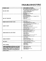
TROUBLESHOOTING
CAUSE/REMEDY
POSSIBLE CAUSE
(SEE INDEX)
Push Clutch/Brake
Pedal into Brake
Move Attachment
Clutch Switch to
Fill Tank with Gasoline, Check Fuel
{clean if necessary) Replace Fuel
Check fuse for fault and replace
Recharge or replace Battery
Check Wiring
Rep,lac,e Spark Plugs and adjust gap
Charge Battery
Replace Ignition Switch
Engage Clutch/Brake
Pedal
Move Attachment
Clutch Switch
to
Replace interlock Switch
Replace Solenoid
WILL NOT START
WILL NOT TURN OVER
Position
"Disengaged
Position
Line and Carburetor
Filter
.
"Disengaged
Replace Starter
Charg e or Reptace Battery
Place Throttle
Control in "FAST"
position
and run starter several times to clear out gas
Remove and clean Fuel Tank and lines
Replace Fuel
Remove Air Filter and clean
Replace Spark Plugs and adjust gap
Replace Battery
Check the wiring and Spark Plugs
Drain Fuet Tank and Carburetor.
use fresh fuet and
HARD TO START
Replace Spark Plug s
Make necessary
adjustments
to Carburetor
..............Major Engine Overhaul
Shift to a lower gear or reduce load
Remove and clean Tank; replace Fuel
Remove and clean Air Cleaner
ENGINE MISSES
Filter
Make necessary carburetor
adjustments
Clean Air Screen
Replace Spark Plugs
Add or change
oil
Check Spark Plugs and check for any loose
Major Engine overhaul
Drain Gas Tank and Carburetor
and refill
OR LACKS POWER
Clean
Air
Screen
Add or change oil
Clean Engine Cooling Fins
Remove and clean Muffler
or replace
Remove and clean Air Filter
ENGINE OVERHEATS
Use
NO LIGHTS
WON'T
Poaition
Replace Fuse
Check All Wire Connections
ENGINE CLICKS BUT WON'T START
fresh fuel and adjust
Carburetor
Check Fuse, Switch and Wire Connections
Replace Headlight
Bulbs
Check for Fuse fault and replace
Replace Battery
Replace Regulator
Replace Alternator
CHARGE
OPERATOR
PRESENCE
SYSTEM
WILL NOT SHUT
DOWN
ENGINE
WHEN
OPERATOR
LEAVES
SEAT
NOTE: THIS TRACTOR IS EQUIPPED WITH AN OPERATOR
PRESENCE SENSING SYSTEM, ANY ATTEMPT BY THE
OPERATOR TO LEAVE THE SEAT WiTH THE ENGINE RUNNiNG AND THE ATTACHMENT CLUTCH ENGAGED WiLL SHUT
DOWN THE ENGINE,
Engage
Check
Check
Check
Check
27
Attachment
Clutch
All Wire Connections
Seat Switch
Operator Presence Relay
PTO Switch
_
wires
Filter
"_
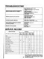
TROUBLESHOOTING
UNSATISFACTORY
MOWER PERFORMANCE
UNEVEN DISTRIBUTION OF CLIPPINGS
Place throttle controla in "FAST" position.
Check air pressure in tires
Check front to rear and side to side mower adjust_
ment
Use a slower ground speed
Replace mower blades
Reinstall mower blades with top of blades up
Re-adjuet mower drive belt
Clean underside of mower deck
Sharpen blades
MOWER
Install new Mower Drive Belt
Reinstall Mower Drive Belt
Replace Attachment
Clutch Switch
Replace Frozen Mandrel
Replace Frozen Pulley
BLADES WILL NOT ROTATE
EXCESSIVE
MOWER
Replace
Replace
VIBRATION
WIND ROWlNGpSTRIPPING,fOR
OF GRASS CLIPPINGS
Bent or Unbalanced
Mandrel, Straighten
Let grass dry out
Clean underside of Mower
Level Mower
Replace Blades
DROPPING
Blade
Deck or replace
Deck
Level Mower
UNEVEN CUT OR SCALPING
Adjust Gauge Wheels
Replace Blades
SERWCE
SERVICE RECORD
Fill in dates as you complete regular service
SCHEDULE
FIRST
2
HOURS
EVERY
5
HOURS
EVERY
25
HOURS
Blades
X
Brake Adjustment
X
EVERY
50
HOURS
'EVERY
100
HOURS
....
Check Battery
Change Engine Oil
_
:
,
,, ,,
,
X
X
X
=
Check Engine Oil Level
X
Clean Air Cleaner Element
X
Check Muffler
X
Clean Air Screen
X
Clean Front Grill
X
Lubricate Tractor
X
,,,,,,,,,,,,,
Replace Spark Plugs
X
Replace Air Cleaner Element
X
Tires
X
2e
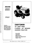
Sears, Roebuck and Co. reserves the right to make any
changes in design or improvements
without imposing
any obligation to install the same upon its terms
heretofore manufactured,
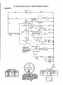
GT TWIN GARDEN TRACTOR
- MODEL NUMBER
917.255919
SCHENIATaC
BLACK
RED
r
RED
CLUTCH/BRAKE
{PEDAL UPt
j
t
WHITE _
....WHITE
POWER
TAKE OFF
SW_TCH r--"_
RED
_CLUTCH
L'3_F
_F&"_--
f
!
t
j
.............
L"-""?,_;
_"_
....
'-S_)_'E N_ID
"°
'7
sO
WHITE
! J
___(
......... _
| C
L.-
ELECTRIC
BLACK
_,_
CLUTCH
RED
2°3°ASSl
M
BLACK
IGNITION
SWITCH
I
!
I
|
SEAT SWITCH
<NOT OCCUPIED)
-OB
BLACK
30 AMP
BLACK
J
L ........
-J
IGNITION
uNiT
SPARK
RED
PLUGS
BLACK
_7
CHASSIS
GROUND
PTO SWITCH
IGNITION SWITCH
POSITION
CIRCUIT
OFF
ON
M-G
B-L
START
B-S
!
POSIIION
WIRING INSULATED CLIPS
NOTE:IF
WIRING
INSULATED
_
CLIPS WERE REMOVED FOR SERVICING OF UNIT,THEY SHOULD
BE REPLACED TO PROPERLY
SECURE YOUR WIRING
29
CIRCUIT
MAKE
OFF
B&E, C&D
ON
B&A
D
I
c
I
I
E
I
B
A
I
.........................................................................
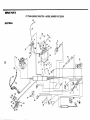
REPAIR
"'"' '""
"' '"'"" '"'"'"'"'"'"'"'"'
'"'"''"'"'"''"'"'""'"'"'"
III
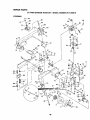
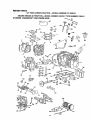
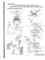
PARTS
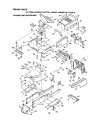
GT TWIN GARDEN TRACTOR
- MODEL NUMBER
917.255919
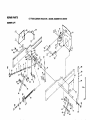
29
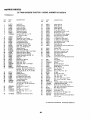
ELECTRICAL
39
C
29
15
1B
B
5O
O
19
21
/
3
33
48
4
2
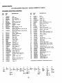
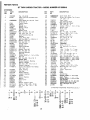
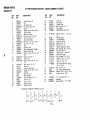
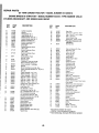
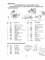
REPAIR PARTS
GT TWIN GARDEN TRACTOR
- MODEL NUMBER
917.255919
ELECTRICAL
KEY
NO.
1
2
3
4
PART
NO.
109310X
STD365402
109787)(
109788)(
4171R
6
7
8
9
10
1!
12
13
14
15
16
17
18
19
20
21
22
23
24
121443X
121_t7X
7603./
100541K
109596X
1o9o81x
10090400
STD541225
17190408
104445X
71031008
73951000
106_315X
121478X
4152J
108824X
74610628
STD523707
121080)(
DESCRIPTION
KEY
NO.
Key
Switch - Ignition
Bezel - ignition
Nut - Ignition
CliD
Switch - Light
Battery
Tray - Battery
Tube - Dram
Clamp - Hose
Solenoid
Washer - Lock 1/4
* Nut- Hex Jam 1/4.20
Screw - Flex Washer Thread Cutting
1/4 - 20 x t/2
Switch - Interlock
Screw - Hex Washer No. 10.32 x 1/2
Nut - Keps No. 10 - 32
Diode Assembly
Harness - Ignition
Bulb - Headlight
Fuse - 30 Amp
Bolt - Hex 3/8 - 24 x I. 3/4
* Bolt - Hex 3/8 - 16 x 3/4
Cable - Ground
2 5
26
2 7
28
29
30
3 !
32
33
34
3 5
36
3 7
39
40
4 !
42
43
44
45
46
48
49
50
51
--*
PART
NO.
DESCRIPTION
t 1050600
4021J
4022J
4799J
719J
74641008
5115J
109550)(
106367X
108170)(
19132203
STD551137
72240460
123198,_
102476)(
STD522507
STD551025
STD541025
STD551125
110859X
121305)(
109748)(
121264X
121493X
121651X
I0!539X
123611X
Washer
Nut.
_12_
13
B
C
14
_ 16
_17
D
'_ 25
Tooth
3/8
""
Flex
Cable - Battery.
CoverTerminal
Screw
1032x 1/2
Cable * Starter
Clutch - Electric
Spacer - Clutch
Stop - Clutch
Washer
• Washer.
Lock 3/8
Bolt - Carnage
1/4 - 20 x 7 - 1/2
"Nut - Wing 1/4 - 20
Guard - Terminal
"Bolt - Hex l/4 - 20 x 3/4
• Washer 9/32 x 5/8 x 16 Ga.
• Nut - Flex 1/4 - 20
• Washer - Lock 1/4
Harness - Light Socket
Switch,Plunger
Relay - Operator Presence
Cap Set * Battery
Ammeter
Decal,Battery
Sheet - lnstructson,
Manual.
Owners
"STANDARD
A
- Lock - Ext.
Switch - P.T.O.
HARDWARE--PURCHASE
F
_
30
Tractor
15 ° Slope
LOCALLY
REPAIR
PARTS
GT TWIN GARDEN TRACTOR
- MODEL NUMBER
917.255919
CHASSIS AND ENCLOSURES
M
93
53
75
P
52
H
11
77
26
1
29
G
32
79
REPAIR PARTS
GT TWIN GARDEN TRACTOR - MODEL NUMBER 917.255919
CHASSIS AND ENCLOSURES
KEY
NOo
PART
NO.
DESCRIPTION
KEY
NO,,
PART
NO
1
2
3
5
6
8
9
10
11
12
13
14
15
120066X
121247X
105529X
73680500
2751R
105513X
73680600
121642X361
106202X
105801X
STD523707
105567X
17490608
16
17490616
17
19
21
22
23
24
25
26
27
28
29
30
31
32
33
34
35
36
37
10551 IX
121067X
!05531X
!05509X
106020X
I21221X
106082X
6999R
7834R
7833R
105465X361
105466X
105464X36I
110892X
1I0893X
7982J
74760716
73680700
108403X361
Seat
Pan - Seat
Bolt - Shoulder
Nut- Lock 5/16- 18
Clip
Bracket- Pivot, Seat
Nut- Lock 3/8 - !6
Fender
Reflector _ Taillight
Decal
*Bolt - Hex 3/8.16 x 3/4
Decal - Chassis
Screw- Hex Washer Thread Rolfing
3/8- 16x 1/2
Screw- Hex Washer Thread Rolfing
3/8- 16x 1
Strap - Fender
Spring - Compression,
Nut- Push
Bracket - Fender
Tank _Fuel
Cap- Fuel
Pad- Spacer
Clamp - Hose
Line _Fuel
Line- Fuel
Footrest - L H
Pad- Footrest
Footrest- R H.
Raft- Frame - R H
Rail - Frame LH.
Drawbar
Bolt - Hex 7/16 - 14 x 1
Nut - Lock 7/!6 - 14
Panel- Side. RH
49
51
52
53
54
55
56
57
58
59
60
61
62
63
64
65
66
67
70
71
72
73
74
75
77
110897X
108067X
106091X
106090X
110350X36!
109139X
106868X
4900J
3645J
8710J
105806X
105568X
19131416
106092X
106088X
I06813X
I06814X
106974X
106909X
106910X
108402X
!2 ! 093X
19131614
I06086X
105036X
39
40
41
42
43
44
45
46
47
48
108410X361
12!054X
121055X
106013X361
110875X
! 05528X
108512X
108513X
106003X
106004X
Panel - Side. L H.
Bracket - Pivot, Frame, R H
Bracket - Pivot, Frame, L H
Hood
Shield- Heat, Front
Grill
Bracket- Pivot. Grill, R H
Bracket- Pivot, Grill, L H
Lens RH..
Lens L H_
79
80
81
82
83
84
85
86
87
88
89
105500X
121144X
19131312
74780816"
10040800
19171912
17490612
121251X
!21246X
121248X
72170410
90
91
92
93
94
95
I2!249X
I21250X
73900400
I05562X
10BZ43X
108744X
A
B
C
@ 81
®9
D
E
F
G
*STANDARD
H
J
_ 71
t 72
L
DESCRIPTION
Bezel
Nut- Pal
Hinge. R H
Hinge- L H
Strap- Grill
Decal. Fender
Decal- Drive Belt Schemattc
Decal. Clutch/Brake
Bushing
Stem - Fuel Tank
Decal- Grill
Decal. Grill(Stripe)
Washer 13/32 x 7/8 x 16 Ga
Support - Heat Shield
Strip- Foam
Decal- Stripe, Side Panel L H,
Decal. Stripe, Side Panel R H
Decal- Caution
Screw. Special
Washer
U-Clip
Cap. Spring
Washer, 13/32x t x I4 Ga
Strip, Foam
Strip, Foam
Retainer, Belt, Lower
Shoulder Bolt. 5/16 - 18 UNC
Washer 13/32x 13/16x 12 Ga.
Screw. Hex t/2 - t3 x "1Gr 5
Lockwasher, !/2
Washer, t7/32x l 3116 x t2 Ga
Screw Hex TrdoRoll 3/8 x 16 x 3/4
Strip, Foam
Switch Bracket
Snap Bushing
Bolt, Carr. 1/4 - 20 x 1 1/4
Spacer, Split
Spring
Nut, Flex Flancle 1/4 - 20
Decal, 18 HoP.
Decal, Stripe L.H.
Decal, Stripe R H_
HARDWA
M
RE-
PURCHA
p
SE LOCA L LY
Q
62
_
O9
83
@
33
R
84
92
REPAIR PARTS
9O
59
I
I
OPTIONAL EQUIPMENT
Spark Attester
K
L
M
Kit
]
REPAIR PARTS
GT TWIN
GROUND
GARDEN
TRACTOR
- MODEL
HUMBER
917.255919
DRIVE
KEY
NO.
2
PART
NO.
110864X
4
6
8
g
I0
1!
12
13
120374 X
110890X
110887X
8545,!
74570412
STD551125
110867X
STD523707
14
15
16
17
18
!9
20
23
25
26
27
29
30
31
32
36
STD523112
STD55113 1
STD541031
73680600
121355X
STD551137
19131614
121063X
101344L
122825)(
122824X
72110614
STD533707
102403X
STD551037
I21356X
37
38
39
40
41
42
43
44
45
46
47
48
49
50
51
54
55
56
57
58
59
60
61
62
63
64
65
66
207J
12000039
121361Xj
STD523715
73930600
12t357X
STD570907
101356L
104360X
121358X
19131413
121360X
104577X
STD523710
17190516
122253X
105598X
100196K
73680500
122268X
110883X
120404X
74760716
STD551143
120332X
9204t"t
104375X
121749X
DESCRIPTION
PART
NO
DESCRIPTION
67
69
70
71
72
73
74
75
76
STD571812
121468X
17720408
121389X
1 t050600
STD547137
8883R
677A637
74370612
77
78
79
80
81
82
83
84
85
86
87
88
89
gO
91
92
93
94
95
96
97
98
99
100
101
102
103
104
105
106
108
109
110
111
112
113
114
715
116
117
118
119
120
122
126
127
74760614
7920J
72140405
STD541025
7229J
1685H
STD533110
5308J
7241J
73530600
100604K
5102J
71673
109767X
110042X
634A692
7563R
12000034
1304H
I06277X361
105588X
7154J
65139
59192
214J
STD541410
633A 109
2228M
74760724
105706X
9858M1
5304,1
74321016
275 t R
104607X
STD522507
73680400
19131210
73680700
11050500
76020816
101358K
19131612
72140506
110895X
120615X
' Pin, Roll, 3/16 x 1. 1/4
Control. Throttle
5cre_ Her, Thd Cur t/4.20 x 7
Control, Choke
W[_.,_herLock Ext Tooth 3'8
"Nut, 3/8.24
Cover, Pedal
Bracket, Brake
Screw, Math., Unct FI Hd,
3/8 - 16 x 3/4
Bolt, Hex, 3/8 - 16 x 7/8
Band, Brake
BolLCarr
t/4-.20×5
8
*Nut, Hex, 1/4 _20
Guide, Rod, Brake
Nut, Lock, 5/16- 18
*Bolt, Carr., 5/16- 18 x 3/4
Rod, Brake
Spring, Compression
Nut, Lock, 3/8 - 24
Yoke
Pin, Clevis
Cap, Plunger
Rod, Parking Brak_
Decal Engine
Bushing and Wheel Hub
Washer, Thrust Axle
Ktip Ring
Bolt, Hub
Wheel, Rear
Tire, Rear
Tube, Tire (Not furnished)
Valve, Tire
Cap Valve
Drum. Brake
*Nut. Lock No 10- 24
Gear Shift Lever Assembly
Key. Woodruff
Boft, Hex 7/16- 14xl1/2
Bearing - Idler
Key- Woodruff
Actuator- Switch, Interlock
Scre_ - Fin 10- 24 _ 1
Clip
Bracket. Interlock
*Bolt - Hex 1/4 - 20 x 3/4
Nut- Crownlock 1/4 - 20
Washer 13 '32 x 3_'4 x t0 Ga
Nut- Crownlock 7/18. I4
Washer- Lock Ext Tooth 5'16
Pin- Cotter 1_a x 1
Bracket ,.Assembly Clutct_
Washer 13/32 x 1 x 12 Ga
Bolt- Carriage 5/16 - !8 x 3/4
Nyliner
Spark Arrester Kit
KEY
NO.
Engine Model Number 422437
Type 1209 Trim01
Valve, Oil Drain
Tube ..Exhaust
Muffler
Gasket. Muffler
Screw. Socket Hd.., 114 • 20 x 3/4
*Washer, Lock, 1/4
Base, Engine
"Bolt, Hex, 318 - 16 x 3/4
Bolt 5/16- 18x 1 _ 1/4
Washer Lock5/16
Nut 5/16- 18
Nut, Lock, 3t8 _ 16
Pulley, Ground Drive
=Washer, Lock, 3/8
Washer, 13/32 x 1 x 14 Ga
Bracket, V-Pulley, Drive, Mule
Pufley
Bracket. Idler, Flat
Guard, Belt, Mule Drive
Bolt, Carro 3/8 - 16x 1_3/4
*Bolto Cart., 3/8 - 16 x 3/4
Idler, Flat
*Washer, !3/32 x 13/16 x 16 Ga,
Bracket, Clutch w/Bearing (Inc. Key
Nee 106)
Washer, Hardened
/(lip Ring
Idler, Grooved
"Bolt, Hex 3/8- 16x 1 3/4
Nut, Lock, 3/8- 16
Spring Extension Clutch
*Pin, Cotter 3/32 x 3/4
Rod, Clutch
Idler, Flat
Retainer, Spring
Washer, 13/32 x 7/8 x 13 Ga
Retainer, Belt
Adapter
*Bolt, Hex, 3/8- 16 x I Gr. 5
Screw, Hex, Thd. Cut5/1618x I
Rod, Shift, Hi-Lo
Bracket, Rod, Shift
Knob
Nut, Lock, 5/16 - 18
Connecting Link Spring Clip
V-Belt
Bracket, Support, _ansaxle
Bolt Hex, 7/16 _ 14 x 1
*Washer_ Lock 7/16
Pulley, Transaxle
Nut, Lock, 1/2 -20
Shaft, Foot Pedal
Washer. 25/32 x 1 - 114 x 16 Ga
*STANDARD
35
HARDWARE-
PURCHASE
LOCALLY
REPAIR PARTS
GT TWIN GARDEN TRACTOR - MODEL NUMBER 917.255919
84
10
10
I
17
/
21
73
\
27
74
5
76
3
2/
79
36
REPAIR PARTS
GT TWIN GARDEN TRACTOR
- MODEL NUMBER 917.255919
STEERING
KEY
NO.
DESCRIPTION
PART
NO°
1
2
106230X
8134H
3
I06228X361
4
5
6
7
8
9
! 0
t i
12
13
! 4
t 5
16
17
18
19
2 0
2 I
22
2 3
2 4
25
26
2 7
2 8
2 9
3 0
3 t
3 2
33
3 4
27BH
9040H
106045X
6266H
! 2000029
5284J
STD523707
73680600
674A244
1309H
5298.!
74781044
STD551 t62
STD541062
6855M
106046X
120424X
110497X
STD551137
STD541737
5292J
t08!37X
19292016
109849X
STD523720
102933X
102439X
104239X
72110608
t01274N
? 74906 t 2
35
3 6
37
38
3 9
40
4 I
42
4 3
44
45
4 6
4 7
102458X
12000034
7007t3N
100711L
!9133808
1060t4X
9038R
t055t9X
120028X
105525×
19171416
72170622
121235X
A
B
Tire. 16 x 650
o
PART
NO
DESCRIPTION
48
I06042X012
Cover.
Tube. Front (not furnished
with
tractor)
Front Wheel (lnc Key No 3 and
of Key No. "4)
Fitting. Grease
Bearing
Spindle, RH
Bearing, Thrust
Klip Ring
Bracket_ Axle
"Bolt - Hex 3/8 - 16 x 3/4
Nut, Lock, 3/8.
16
Axle. Front (Inc. Key 13)
Bearing
Tube. Pivot, Axle
Bolt. Hex 5/8-11 x 2-3/4 Gr 5
"Washer.
Lock 5/8
*Nut, He_ 5/877
Fitting. Grease
Spindle,
L H
Sector Assembly
Link. Drag
*Washer, Lock 3/8
4 9
17720408
50
5 I
52
53
54
55
56
57
58
59
60
6 I
62
6 3
64
65
6 6
6 7
68
6 9
70
t05810X
!00710L
74760880
73680800
19172670
120542X
677A457
7790J
5TD523720
79137473
STD541037
5273J
73680500
7985J
65739
59792
Screw, He× Washer
t4-,20x72
Decal, Insert
°Nut, Hex 3/8 - 24
Bushing,
Beflcrank
Bellcrank
Washer 29/32 x t - t/4 x 76 Ga
Rod. Tie
*Bolto Hex 3/8 o t6 x 2 Gr 5
7 1
72
73
74
75
76
I09851X
7919J
73700600
5TD_4!337
STD533!07
"Nut.,
Hex 3/8 -, 16
Bracket
Frame Fror't
Nut Lock 5 16
18
Support
Ba:ter_
Stem
Va:_ e
Cap _.'a!_e
.Joint ,, T_e ROC , R r" T_.eac
Jomr,
T;e RoC , L t= T_'eac
Rod.
Tie
Nut., /'-Y,
ex Jam 3/8 - 24 L H
108367X
120199X
86
Sleeve. Steering
Bearing
Dash_ Lower
Dash
Bracket,
Support,
Dash
Washer 17/32 x 7/8 x 16 Ga.
Bolt _, Cart .3/8 . 76 x 2
3/4
Ins:rut:or
fVtour, ttrc
Jc €,1 _,acke;
"Nut ,, He_ Jam 3/8., 2 _I
"Bo_r ,, Carriage 5/t6 .. 18 _ 3/.i
Washer
13/32x
1 - 1/4 x I6 Go.
Washer 25/32 x i - 5/8'x 16 Ga.
Bolt He_ 5./76 ,, 78 _
Cap., Hub Fron'_
121177X
Bushing _,Handle
Washer
11/32 _ 7/8 _ ; 6 Ga
"Bolt. Hex 3/8 ,. 16 x t Gr 5
Clip . 3/8
Decal -, Adlustment
Tube
Collar
87
110946X
Spindle
88
19133807
Washer 13/32 x 1 - 1/4x 7 Ga..
89
8022J
90
91
121748X
121232X
Dash
Plug
Washer 25/32
92
93
94
95
74180412
19091216
73510400
4171R
Spacer
°STANDARD
H
J
K
Stop
x 1.5/8
29
@
Screw, Mach. Cr, I/4 - 20 x 3/4
Washer 9/32 x 3/4 x 16 Ga,
Nut - Hex Keps 1/4 - 20
Clip
HARDWARE,,.,PURCHA
L
M
_45
@ 22
22
"
22
6o
@ 45
['_ 47
@
6o
37
x t6 Ga_
Cap, Spindle
5E L OCAL L
N
( B2
,._,'359
Ga
',6 _ 2 i/4
x 78 x 1,3Go
!09850X
84
85
U
Spring
"Bo_t _e_ 378
Washer
;3/32
5 8 x !0
Clip
Shaft, Steering
Klip Ring
Wheel, Steering
Adapter.
Steering
Washer
U
Nut, Lock 1/2 .. 13
Washer 17/32 x !
Bracket
Idler
Pulley
Idler
2751R
74930516
704757X
100644K
79111416
5TD523770
100207k
G
Wheel
"Bolt - Hex 1/2 - 13 x 5
Pin
78
79
80
8 7
82
83
F
Cuthnc
Deca,
Bracket,
Support.
Steering
Bearing. Flanged
Bolt, Cart 3/8 ,, 16 x 7 Gr, 5
Support.
Steering
Screw,
Hex Washer Thd Rolling
3_8 ., 15 × 34
E
Steering
Thd
Dashplate
121749X
121748X
D
Cap,
Shift
108456X
t06615X
77
C
Gate.
121377X011
Spacer, Split
®1!
li
KEY
NO ,,
22
Bo
€_ 80
@
J_
62
REPAIR PARTS
MOWER
GT TWIN GARDEN TRACTOR-
MODEL NUMBER 917.255919
LiFT
15
D
64
65
/
25
\
64i
6
2
ca
23
16
4O
53
/
"46
41
/34
43
42
i
6O
\
2
K
58
\
59
33
35_
REPAIR PARTS
MOWER
GT TWIN GARDEN TRACTOR
LIFT
KEY
NO.
PART
NO.
1
2
3
4
5
6
7
8
9
!0
11
12
!3
!4
!5
!6
!7
!8
!00734K
110807X
!!0811X
STD570907
2876/'1
19131016
121794X
! 10871X
STD523107
73680500
t 20350X
STD522505
73680400
!06351X
t 10436)(
73350600
105040X
74 750806
- MODEL NUMBER
DESCRIPTION
Handle,
Nut
Adiust,
Rod, Adjust,
Lift
"Pin, Cotter.
3/32
KEY
NO,
Lift
STD551108
105041X
STD511005
22
23
24
25
26
27
28
29
30
3!
32
33
73631000
120137X
108t0X
19151216
12000037
7594J
790 lJ
73900400
7596J
105503X
4939M
74760 616
105723X
STD523710
3 8
3 9
!09413X
74780624
40
STD55
4 I
4 2
43
44
4 5
4 6
4 7
4 8
49
9135R
!05429X
105413X
STD551150
STD54 I050
105501X
STD533707
73680600
674A247
50
110908X
5 1
52
53
54
55
STD5331
19111610
121045X.
I21046X
17490608
5 7
58
59
60
STD54t037
5328J
STD551037
5329J
x
Shaft, Lift
Trunnion,
Stop Depth
Washer
15/32 x 3/4 x 16 Ga.
Klip Ring
Bracket. Lift, L,H.
Bolt, Shoulder
Nut. Hex Flange 1/4
20
62
Link. Lift, L,H.
Link. Lift, R.H.
Retainer.
Spnng
Washer, Lock 3/8
*STANDARD
B
(_12
C
_
@13 ©1o
_
E
18
.@ 19
7050
*Washer
Ga.
17/32
Bracket, Suspenston,
*Bolt, Carriage, 3/8Nut, Lock. 3/8 - 16
tO
_
2'
_
022029
G
28
_
Spring - Ass'v,
-Asstst,
Lift
Guard, Belt. Engine
"Bolt, Carnage,
5/16 * 18 x 1
Washer ! 7/32 x ! x 10 Ga.
Panel, pnt, Side, R.H.
Panel, pnt, Std#, L.H.
Bolt, Hex Washer Thd. Rolling
3/8
16 x 1/2
Bracket,
Nut
Spring
i151
©62, 5z
@1o
• Asslst
Centerlock 3/8 • 16
Klip Ring
Washer 29/32 x ! - 1/4 x 16 Ga.
Ft
47
Mower
16 x 3/4
"Nut, Hex 3/8
16
Bolt • Adjust, Spnng, AssJst
"Washer
13/32 x 13/16 x 16 Ga,
12000022
19292016
F
x ! - 1/16 x 13
Retainer Spnng
Arm, Suspension
Stud, Pivot Center
"Washer,
Lock, 1/2
"Nut, Flex, 1/2 • 13
LOCALLY
D
9
Plunger, Lever
"Bolt - Hex 3/8 - 16x 1
Grip, Handle
Bolt, Hex 3/8 - 16 x 1 I/2
73930600
64
65
HARDWARE--PURCHASE
Lever Lift
Rod, Detent
36
37
Spring
Washer
13/32 x 5/8 x 16 Ga.
Cover, Access
Shield, Heat, Rear
*Bolt, Hex. 5/!6 _ 18 x 3/4
Nut, Lock, 5/16 * I8
Brace, Heat Shield
"Bolt, Hex, 1/4 - 20 x 1/2 Gr, 5
Nut, Lock, 1/4 , 20
Plug
Grommet,
Split
Nut - Flex Jam 3/8 - 16 UNC
Bracket, Fuel Pump
Screw.
St. Hex Hd. No, 8 . 32 x
"Washer, Lock No, 8
Pump, Fuel
"Screw, Hex Hd, No. 10 - 24
t/2
Nut. Lock No. 10 _ 24
DESCRIPTION
121002X
t2'1006X
3/8
19
20
27
PART
NO.
34
3 5
x 3/4
917.255919
K
J
_
55
_
37
Q
48
REPAIR PARTS
GT TWIN GARDEN TRACTOR - MODEL NUMBER
917.255919
MOWER
47_
%
I_
44
42
53
12
/
38
45
35
53
35
39
/
51
40
69,_
35
38
35
6O
9
4O
REPAIR PARTS
GT TWIN GARDEN TRACTOR-
MODEL NUMBER 917.255919
MOWER
KEY
NO0
PART
NOD
1
2
3
105415X
106022X
17490508
4
5
6
7
8
9
Z0
1 1
12
13
14
763 IJ
72110505
S10551131
STD541031
8418J
72740506
1685I-I
STD551037
! 5
16
I 7
18
t 9
2 0
2 1
,2 2
23
24
2 5
2 6
2 7
28
29
30
3 1
106635X
STD623715
STD557137
19132012
674A213
7834J
7835J
72110522
19111610
102403X
STD523715
STD54 1037
104361X
51D523112
191 ! 12t6
8438J
106224 X
32
33
34
35
DESCRIPTION
KEY
NO
PART
NO.
DESCRIPTION
3 6
3 7
3 8
39
105453X
5565J
4939M
4898H
Bar, Ga Wheel
Pin, Clevis
Runner, L Ho
BsIt. Cart 5/16.,
18 x 5/8
"Washer ,, Lock, 5/16
"Nut . Hex 5/76 - 1B
Runner, R H
Bolt_ Cart 5/16 - 18 x 3/4
4 0
4 I
4 2
43
44
45
105455X
105433X
110237X
105434X
105436X
105447X
Wheel, Gauge
Brkt.
Suspension
Spacer
Brace, Suspension
Parallel Link
Nut. Lock 5/16.
18
"Washer
! 1/32 x 11/16
4 6
4 7
121343X
3146R
Mandrel.
Secondary
Mandrel - Primary
Screw - He× Washer Thd Rol!
3/8 _ 16 x 3/4
Blade
"Bolt
He_, 3,/8-24 x 11/2 Gr 5
"Washer,
Lock, 3/8
Washer
13/32 x I - 1/4 x 12 Ga
Arm Assembly,
Idler
Liner. Bearing
Bearing
Bolt. Carriage 5/16 - !8 x 2
3/4
Washer 11/32 • 1 x !0 Ga
Pulley, Idler
"BoltHe× 3/8.
16 • 1
I/2
"Nut v Hex 3/8 . 16
Spring
"Bolt - He_ 5/16.18
_ 1.1/4 Gr 5
Washer 11/32 _ 3/4 x 16 Ga
4 8
4 9
50
5 t
52
53
54
55
5 6
5 7
58
59
60
6 I
62
63
64
65
66
106381X
STD54 7050
74760622
105435X
3720R
12000039
19171612
I05440X
105458X
105460X
105461X
105459X
73680500
120135X
19111016
109785X
t 06734 X
109743X
106735X
Spacer
DecalV-Beft, Dr , Schematic,
Mower
Bracket, Ga Wheel, R H
Bracket, Ga Wheel. L H
"Bolt. Carriage 3/8 . 16 × 3/4
Nut, Crowntock
3/8
!6
6 8
69
70
110452X
3713J
- - -
7 1
73
74
76
73680800
19171512
72240608
110884X
77
78
19131614
121352)(
Housing, Mower
Cover.
Drive, Deck
Screw - Hex Washer
5/1618 x 1/2
1216Ei8X
121657X
17490612
705448X
105449X
STD533707
73680600
Thd
Roll
x 16 Ga
"STANDARD
A
B
C
D
E
F
l!
It
4t
G
o0
H
;
[i
Retainer.
Spring
Bolt. Shoulder
Brkt,
Suspension
Decal., Warning
Retainer
- Spring
V-Belt
"Nut.
1/213
Bolt. He_ 3/8.
16 × I . 3/8
Pin. Release
Spring
Ring, Klip
Washer
17/32 _ t x 12 Ga
Pin. Clevis
Brkt.
Outer, RH
Brkt.
Inner, R H
Brtk , Inner, L H
Brkt . Outer. L H
Locknut
5/16,
18
Spacer
Washer
11/32 _ 5/8
Shield. Deflector
_ I6 Ga
Spring, Deflector
Bracket.
Deflector
Rod, Hinge
Push Nut
instruction.
Caution
Decal
Decal - Safety Standard
. Not Serviced
Lock Nut - Flex I/2 - 13
Washer
17/32 _ 15 t6 _ 12 Ga
Bolt. Carriage 3/8
16 • t
VSett
Washer
13/32 x 1 x 14 Ga.
Keeper, belt
HARDWARE-PURCHASE
I
74
9
®
LOCALL
Y
REPAIR
PARTS
TRANSAXLE
GT TWIN GARDEN
t
TRACTOR - MODEL NUMBER
4
917.255919
5
4
6
1
2
7
t5
14
!3
37
38
39
40
24
f97
_98
/
IlqlllII IIIIII1'11111
I
42
IIIIIIIIII
REPAgR
PARTS
GT TWIN
GARDEN
TRACTOR
- MODEL
NUMBER
917.255919
TRANSAXLE
KEY
NO
1
2
3
4
5
6
7
8
9
10
11
12
13
14
15
PART
NO
DESCRtPTIO_J
KEY
NO
4197R
5645R
4t99R
4216R
4215R
4217R
6256H
74020652
Axle Shaft
Retaining Ring
Final Drive Gear
Differential
Gear
Differential
Pinion
Differential Carrier
Axle Thrust Washer
Hex Bolt 3iB 24 x 3 I/4
(1" Thread Length)
Steel Ball
Spring Shift Fork Detent
Shift Fork, High Low Range
Thrust Bearing Race
4th Reduction Pinion
3rd Reduction Gear Shaft
SnaI_ Ring -_Crescent Type
High Low Range Gears
Needle Bearing
Sintered Iron Bearing
Shift Fork Shaft. High - Low Range
Differential
Pinion Spacer
Differential
Pinion Bushing
Gripco Centerlock Nut 3/8 24
Shift Fork- LH
Oil Seal
Sintered iron Bearing
Shift Fork Shaft
Shift Fork. RH,
Shift Shaft, High Low Range
Oil Seal
Pressure Relief Valve
Gearcase, Reverse idler Shaft and
Bearings R.H (inc. Key No's t7
t8, 25, 33, 50.63, 76, 77 and 82)
Dowel Pin
Needle Bearing
Thrust Bearing Race
4th Reduction Gear Shaft
4th Reduction Gear Spacer
Thrust Bearing Race
Gearcase Gasket
49
50
51
52
53
54
55
56
57
58
59
60
61
62
63
64
4895H
4222R
1529R
8119M
4220R
4209R
42! 3R
4442R
4195R
4214R
4194R
r7528R
4208R
4207R
7398H
4203R
65
66
67
68
69
70
71
4204R
2898J
4926H
4205R
4206R
!370H
633A69
72
73
74
75
76
77
7B
79
B0
81
82
B4
85
86
87
8B
20BJ
4201R
12000002
1153R
7392H
3990H
73220500
1167R
73360700
6270H
7384 H
53B4,J
297BJ
633A85
B739H1
4924H
89
90
91
92
93
g4
95
96
97
98
19151516
110542X
19181511
7bJ
6274H
76020412
10040500
74760514
633A109
122419X
31
7392M
6272H
4985R
6266H
4212R
4196R
6276H
633A63
8118M
8740H1
122238X
4218R
6252H1
78t0H
4986R
7393R
992R1
6216H
6262H
122254X
6296H
5855H
122162)(
32
33
34
35
36
37
38
6277H
4225R
7396H
419BR
4200R
7395H
121878X
39
122,11B.3X
4O
45
46
47
13320400
6271H
13060200
74780524
48
10140500
16
17
18
19
2O
2!
22
23
24
25
26
27
28
29
3O
Gearcase and Bearings -, L,H.
(tnc Key No's 18, 25. 49. 50 (2L
51 and52)
Pipe Plug t/2 - 14 N PT
O11 Seal
Pipe Plug t/4. t 8 N P T
"Hex Bolt 5/16
18 x 1 ,, 1/2
Grade 5
Lockwasher 5/16 Extra Heavy
PART
NO
DESCRIPTION
"
"STANDARD
43
Needfe Bear tng
Needte Bearing
Needle Bearing
Needte Bearing
Thrust Bearing Race
3rd Reduchon Pinion
Low
4th Reduction Gear
3rd Reduction Pinion Spacer
2nd Reduction Gear Shaft
Fsnal Drive Pinion
1st Reduction Gear Shaft
1st Reduction Shaft Spacer
3rd Reduction Pin=on., High
2nd Reduction Gear
Needle Bearing
Low Speed Gear and 2nd Reduction
Pinion Cluster
Reverse Gear
Key-Hi.
Pro 1 B x t7 32
Snap Ring ,. Crescent Type
Intermediate Speed Gear
High Speed Gear
Thrust Bearing Race
Intermediateand High Speed Clusler
Pinions
Input Shaft
Low Speed Pimon
E. Ring
Reverse Idler Gear
Reverse Idler Thrust Washer
"
Needle Bearing
"Hex Nut 5/16
18
Seahng Washer
Hex Jam Nut 7116 20
O_t Seal
ReverseIdler Shah
Gear Shdt Lever Bent
Gear ShiftCap
Gear ShdI BaliCover arid Pin
Shi!tLever Gu,de Bali,,Keyed
Spring
Washer 15/32 x t5/t6 x 16 Ga
Shift Mechanism
Seal
Washer g/16 x 15/16x
t2Ga
Gea_ Shift Gate and Reinforcement
Shdt Ball Cover Gasket
Cotter ltB x 3/4
"Lockwasher
5 16
"HexBoIt5/16
18UNCx7/8
Gear Shdt Lever Ass'y,
Transaxle Assembly Less Brake Drum
& Sh=ftLever
HARDWARE
PURCftASE
LOCALLY
REPAIR PARTS
GT TWIN
ENGINE
CYLINDER,
BRIGGS
GARDEN
TRACTOR
& STRATTON
CRANKSHAFT
AND
- MODEL
ENGINE
- MODEL
NUMBER
NUMBER
422437,
917.255919
TYPE
HUMBER
1256-01
BASE
..+,10
_"
_---70
"_46
_69
lo__..,
v
e_ --'4s
55
3
6
38
9
9
48
37
59
32
28
/
61
33
20
19
A,4
REPAUR PARTS
GT TWIN GARDEN TRACTOR - MODEL NUMBER 917.255919
ENGINE BRIGGS & STRATTON
CYLINDER,CRANKSHAFT
KEY
N O.
PART
NO.
- MODEL NUMBER 422437, TYPE NUMBER
AND ENGINE BASE GROUP
DESCRIPTION
KEY
NO
PART
NO
34
35
212337
491287
Gear.Cam
36
296004
Pipe ,, Fuel 23 ' cut to length
Gear o Governor
0t
02
03
04
05
06
07
O8
09
1o
tt
491685
391086
Cylinder
Seal.Oil
212461
Head-Cylinder
No.
212462
271867
Head-Cylinder
Gasket-Cylinder
No 2
Head
No.
1
37
38
394348
89838
271868
Gasket.Cylinder
Head
No
2
39
220863
393243
393153
27803
94382
Breather Assembly
No
Breather Assembly
No
Gasket-Valve
Cover
Screw-Sere
40
394539
270982
Gasket.Crankcase
1/64" Thick
Cover
ti
271145
Gasket.Crankcase
005"" Thick
Cover
11
27! 146
Gasket.Crankcase
009"" Thick
Cover
t3
93211
14
15
91084
1256-01
Assembly
Screw-Cylinder
(2-21/32"
long)
Plug-Oil Drain
!
I
2
Head
41
90576
44
398924
45
46
68838
280220
47
48
93783
223055
49
50
51
394391
270981
222700
DESCRIPTION
Foam
Seat -, Governor
Wrench.Spark
Washer-Gov
** Plug.Spark
Shall
Plug
Crank Ims_de)
(Resistor)
2-3/8
high-6Omm)
Nut.Hex
8.32
Cap and (]ipslJck.OJl
Seat-Filler
Tube
Tube * Od Filter
Screw-Hex
F_i_er
Hd
Trough,Dipper
Base-Engine
Gasket.Engme
Guide Air
Base
394430
Crankshaft
- order part 94196
Key tor retaining timing gear
52
53
93053
94296
I6
17
18
t9
394535
29 t 675
Cover Assembly
Seal-Of
54
55
491530
68538
93847
Screw.Crankcase
56
93448
394955
t9
19
19
20
20
2O
20
2I
394956
Piston Assembly.Standard/nc
20 & 22)
Piston Assembly - 010" 0 S
57
58
59
222696,
220863
222773
394957
394958
Piston Assembly.
Piston Assembly.
020" O S
030 °_0 S
60
61
231445
393606
Gear,.Timmg
Seal Ass y
394959
394960
Ring
Rittg
- Standard
- 0t0'
0 S
62
63
393741
261961
Bearing.Bait
(P T 0 s_del
Guide-Exhaust
Valve
394961
394962
Ring Set - Piston - 020"
Ring Set. Piston - 030"
398990
Dipstick
64
210940
22
23
260924
Key No's
44, 45 & 46)
Lock-Piston
Pin
65
86
261463
262332
23
24
39 t286
Pin Assembly.
Piston
Standard (lnc, Key No 22)
Pin * Assembly*Piston005-
67
68
69
398808
230318
9279 I
394306
Rod Assembly-Connecting
70
93722
For Connecting
Rod with 020"
Crankpin
bore order No 397158
71
72
261528
92268
223053
92909
390420
Dipper.Connecting
Screw.Connecting
Valve-Exhaust
73
74
75
49 I523
262331
93886
65906
Spring-Intake
76
27t t70
Bearing,.Cyhnder
Upper Bushing.Governor
Screw
Sea! Tube
26828
221596
Spring-Exhaust
Retainer-Intake
77
78
27t t 74
223882
Gasket.
Washer
292260
Rotocoil.Exhaust
93630
Retainer-Exhaust
261368
Tappet-Valve
25
26
27
28
29
30
31
32
33
299691
- Crankcase
cover
Set - Piston
Set _ Piston
and
Mlg
Sem
Key No
s
Clamp-Fuel
Pipe
Retainer.ERing
Crank.Governor
Elbow-Spark
Washer.. Thrust
NOTE
0 S
0 S
Tube Assembly
(lnc
0 S
Rod
Rod
Valve
Valve
Valve
"INCLUDED
Valve Roto_ Cap
+ SPECIAL
and Retainer
231218
Only (Brass)
Seat.Exhaust
Seat.Intake
Intake
Valve
Valve
Guide
(Standard)
Valve (Standard)
Lower Bushing
Wire.Ground
,, Gev
Connector.Fuel
Washer.Lock
P_pe
Shakeproof
TermJnal,,Spade
Valve.Intake
Washer
IN GASKET
TOOLS
Plug
Ptug.,Hex Socket
Key.Flywheel
Washer
Exhaust
- Gov Shah
SET 394501
REQUIRED
TO iNSTALL
** Use resistor plug, Champion RJ19LM or eqivalent
45
REPAIR
PARTS
GT TWIN GARDEN TRACTOR
ENGINE BRIGGS & STRATTON
AIR CLEANER--CARBURETOR
- MODEL NUMBER
917.255919
- MODEL NUMBER 422437, TYPE NUMBER 1256-01
GROUP
38
37
30
33
36
32
U-2,
68
_.9
16
59
\
27
3
5
J_6
73
I GASKET
]SET
i71
46
Carburetor
Overhaul
Kit,,J
REPAnR
PARTS
GT TWIN GARDEN TRACTOR
ENGINE BRIGGS & STRATTON
AiR CLEANER--CARBURETOR
KEY
PART
NO.
NO.
- MODEL NUMBER
- MODEL NUMBER 422437, TYPE NUMBER
DESCRIPTION
280819
280 I98
Tube.Breather
Tubeqntake
3
4
213288
271412
ManifoldAss'y
+ *Gasket-Carb,
5
6
270884
93415
Gasket.Intake
Screw Carb
7
94367
Screw
8
491630
Carburetor
9, 10, 1I,
KEY
NO.
31
32
Intake
Mtg
Manifold
Mtg
MTG Sere
Intake
Manifold
Mtg
Sere
Ass'},
(Inc Key No's
12. 13. 14_ 15. 16, 17,
PART
NO,
28, 44, 46, 47, 48, 49. 50, 51,
6!,63,64&65
Body
(Inc
Assembly
- Upper
Key No°s
Carburetor
10, 13, t8. 23 &
24)
10
230318
Connector.
11
231209
Bushing*Throttle
Fuel
t2
!3
491538
93499
+ Valve Ass'y-Carb
Screw-Throttle
and
t4
221939
Mtg Sem
Vafve- Throttle
15
392672
Shaft
16
91920
Screw.Mach
17
26157
Spring.
18
271607
+ "Gasket-Carburetor
19
20
21
298514
230896
394681
Float.Carburetor
Body
+ Pin-Float
Hinge
+ Valve-Fuel
Inlet
22
491665
23
24
223534
392673
Body - Lower Carburetor
(lnc
No's
11, 13. 14, 15 & 65)
Valve-Choke
Shaft and Lever-Choke
25
94152
Screw-Hex
27
93897
28
231338
29
30
222752
212706
Shaft
Idle
Choke
Valve
and Lever-Throttle
Head
Screw-Casing
°Jet-Needle
Body.Air
Knob.Air
Fil lid
Throttle
8.32
x 5/8
Nut.Hex
Link Governor
33
94298
Nut.Square
34
35
262351
251563
Spring.Governor
Spring - Governor
36
491282
Bracket.Speed
37
38
262337
94297
Spring.Compression
Screw Pan Head
39
491298
40
222289
Lever Ass'_'
Governo,
Nos
40 55 & 56)
Washer
4t
43
223882
93893
Washer
Screw_Sem
44
52
397882
271271
Plug (lnc Key No
73 )
Element.Air
Cleaner
53
271411
54
271180
Washer
55
56
93853
92278
Bolt.Governor
Nut,,Hex
57
223001
Cover-Air
58
59
222835
93868
Cartridge Plate.Air
Screw-Sere
60
392643
Mounting
62
63
67
394018
27t013
394358
(Inc Key No 43)
Cartridge.Air
Cleaner
+ Washer,Choke
Shaft
Filter.Fuel
68
93053
Clamp-Fuel
69
393815
70
394501
Fuel-Line
(cut to required
length )
Gasket Set
7t
491539
Carburetor
72
223472
Plug.
73
280474
O.Ring
Adj
Sem
Body
Key
10/32 x 3/4
Clamp
DESCRIPTION
93715
262333
18, i9, 20, 21, 22, 23. 24, 25,
491541
1256-01
GROUP
I
2
9
917.255919
Idle
Control
+ Gasket, Air
dnc
Key
Cleaner
Lever
Cleaner
Strap
Cleaner
Assay
Air Cleaner
Pipe
Overhaul
Kit
Welch
Seat
Valve
Cleaner
Cleaner
"INCLUDED
IN GASKET SET
+INCLUDED
IN CARBURETOR
OVERHAUL
°For high altitude - use jet # 231333
47
KIT
REPAIR PARTS
GT TWIN GARDEN TRACTOR
- MODEL NUMBER
917.255919
ENGINE BRIGGS & STRATFON - MODEL NUMBER 422437, TYPE NUMBER
1256-01
9
18
KEY
NO o
I
PART
NO.
394891
DESCRIPTION
Armature
Group
KEY
NO_
(lnc
Key No's
PART
NQ
394970
Trigger
Ignition
Coil
Assembly
3
4
22t 798
93381
Terminal - Ignition
Screw.
Armature
394808
19
390837
Amature
20
2I
394860
398003
Drive
22
280 I04
23
24
90366
9t 162
Lockwasher
25
393254
Kit. Pinion Spring
22&26)
Roll Pin
ScrewHex lid
23 & 24)
Magnatron
Cable
Mtg Sere
5
394988
Armature
6
7
49I 180
93821
Flywheel
and Ring
Screw - Sem
8
9
223726
392595
Retainer-Fan
Stator * Alternator
10
39 t362
Gear - Flywheel
Mounting
Parts)
26
94192
11
12
280815
213472
Fan - Flywheel
Fan - Booster
27
28
94385
223008
13
93535
Screw-Sere
29
230674
14
19203
Puller - Flywheel
Accessory)
30
31
393537
93808
15
!6
94003
395538
Thru Bolt
Brush Set
33
398865
17
395537
Commutator
34
35
222511
393825
Starlet'
MUFFLER,
AIR GUIDE
Ass'y
(lnc
AND
Gear Ass'y
_ Magneto
Ring (Includes
(Optional
End Cap Assay Key No
16)
HOUSING
GROUP
Motor .. Starting
(inc Key No s
13. 15, 16, 17_ 19_ 20. 21 22
t8
23&5)
2
DESCRIPTION
Assembly
End
Clutch
Gear
Screw
1/2"
(Motor)
Cap Ass'),
- Hex
Hd
. 5/16 - 18 x t .
(Inc
PART
NO
1
49 t243
Housing-Blower
2
3
93158
93777
ScrewSere
Screw - Hex H
4
5
491444
222848
Back Plate Assembly
CoverAir Guide
6
7
8
9
222846
93163
223734
222849
Shield- Cylinder
Screw - Sem
Shield * Cylinder
Cover - Air Guide
Key No_s
Screen.
Rotating
Nut - Hex
Connector.
Tri Circuit
Screw-Sere
Starter Drive Group (Inc Key No_s
21. 22,25&26)
Washer. Spring
Housing Assembly
4
J
KEY
NQ
- Starter
Ass'y
DESCRIPTION
s
[
AttachmentsThat Addto the Usefulnessof Your CraftsmanGardenTractor
Searsoffersa widevarietyofattachmentsthatfit yourtractor.Manyofthesearelistedbelowwithbriefexplanations
of howtheycanhelp you.This
list wascurrentat the time ofpublication:however,it maychangein futureyears-- moreattachmentsmaybe added,changes(includingchanges
in thestocknumber)maybe madein theseattachments,
orsomemaynolongerbe availabTe.
Mostoftheseattachmentsdo not requireadditionalhitchesorconversTon
kits (thosethatdo areindicated)and aredesignedforeasyattachingand
detaching.
Youmayordertheseattachmentsat mostSearsretailstores,catalogsatesoffices,
and throughthe catalog.
LAWNSWEEPERS
letyoucollectgrassclippings
andleaves°
StockNo.
71-24030
71-24032
71-24033High-Performance
71-24038
Palh
30-in.
32-in,
32 in°
38-ino
Capacity
9,0cu. ft.
10o0cu_ft.
11o5cuoft_
12_5cu_ft,,
LAWNVACSfor powerfulcollections
ofheavygrassclippings
andleaves.All acceptWandattachmentto pick up debrisin hard-to-reachplaces,
StockNo.
71-2455
71.2452
71-2447
Engine
3HP
3HP
5HP
Capacity
8 bu,
t2 buo
25buo
ArsoRequired
71-26471chute
71-26471chute
71-24474chute
10cuoft, cart
CARTSmakehaulingeasy.
StockNo,
Size
Capacity
71-24353
71-24354
71-24355
71-24356
71-24357
4 cu.fl.
10cu.fL
10curft.
!4 cu.IL
17 cu.fro
400 ibo
1,000lb.
1,000tbo
1,250lb_
1,500 lb.
Dumpcart
Haulingcart
Dumpcart
Dumpcart
Dumpcart
ROLLERforsmootherlawnsurface.36-inchwide,18 inchdiameterwater-tight
drumholdsupto 390 iboof weight,Roundededgespreventharmto
turf,,Adjustablescraperautomatically
cYeans
drum.Stocknumber71-24084.
SPREADEPJSEEDERS
makeseeding,realizing,and weedkitlingeasy_Broadcastspreadersare alsousefulforgranularde-icersand sand,
71-24!94
71-24394
Droptype,36 inch.12in, semi-pneumatic
wheels.100lb. capcitysteelhopper,
Broadcastsover a 5 to 8 foot swath.,70 Ibncapacitysteel hopper,Noncorrosivespreadings_,,_ner,nylon gear box,
stainlesssteelshaft,
71-24395
Broadcasts8 to 10 foot swath,t60 tb, capacity.(covers40,000sq ft,)No-nJstpolypropylenehopperand impeller Vinyl
hoppercover.
Broadcasts6 to8 foot swath.50 lb.capacity.Corrosion-resistant
construction°
Polyethylenehopper,
71-2416
CORINGAERATORtakessmallplugsoutof soiltoatlowmoistureandnutrientstoreachgrassroots,36_inchswath 24 hardenedsteelcoringtips,
150lb.,capacityweighttray,,Stocknumber71_24351
AERATORpromotesdeep root growthfor a heathy lawn_Tapered2 5"steel spikesmountedon 10-in diameterdiscspunctureholes in soilat
closeintervalsto letmoisturesoakit,.Steelweighttrayfor increasedpenetration,
_;tocknumber71-2435."
DETHATCHER
loosensand flipsthatchand mattedleavesIo lawnsurfacefor easypick up.Twentyspringline teeth,,Usefulto preparebare areas
forreseeding.40 inchrearmount:Stocknumber71-24313.38 inchfrontmount:Stocknumber71-24301,.
SPRAYERSuse 12-voltDC electricmotorthatconnectstothetractorbatteryor other12-voltsource,Includesboomsfor automaticspraying
when
pulling,and hand held wand for spot spraying,Wandhas adjustablespray pattemoFor applyingherbicides,insecticides,fungicides,and liquid
fertilizers.
71_458
50 psi maximum
pressurewith25 footwandlengthoSpraysupto25 feetwith wand.
71-24398
25 psimaximumpressure
withI8 footwandlength°Spraysup to18 feetwithwand,
DOZERBLADEremovessnow;gradesdirt, sandandgravel.48 incheswide,17 incheshigh,cears44 inchpathwhenangled.Masterlilt contro?e
leverfor operatorease.Springtripfor snowremovalon unevenpavemeni;
built- in floatfor bladeto followgroundcontour.Reversible,replaceable
scraperbar.(Usewithtire chains,wheelweights
or reardrawbarweight).StockNo. 71-24402
SNOWTHROWER
has 42-inchswath,Drum-typeaugerhandlespowderyand wet/heavysnow°Mountseasilywith simplepin arangemenLDis.
chargechuteadjuststo240degreearcfromtractorseat.6-inchdiameterspoutdischargessnow 10to50 ftoLift contro!led
at tractorseat°(Usewith
life chains,wheelweights,or reardrawbarweight)°SIockNoo71-24074
TiRECHAINSareheavyduly; closely
spacedextra-largecrosslinksg_vesmoothride,outstanding
traction°
StockNo. 71-26946_
49
WHEELWEIGHTSprovidestability,
reducetearingoftuffwhenmovingonhills,stopping,
turning,starting.Providesextraweightfortractionto pull
low-loads,lawnvac. Requiredfor snowremoval.For plowing:
onein front frame,one/n right rear tire, two on left reartire. For snowbloweror
dozerblade:one on right rear tire, one on left reartire.55 pounds°StockNo. 71-26234.(Frontor rear mountingframebracketStockNo. 7126235_)
CHEVRONTIRESfor extratraction.
Pairofrear tiresmountedonwheets,StockNo. 71.24167.
TRACTORCAB has heavyduty vinyl fabricovertubularsteel frame,fiberglass
top; clear plasticwindshield
offers360 degreevisibitity_
Hinged
metatframedoorswithcatch.Keepsoperatorwarmand dry. Removevinyl and windshieldfor use as sun protectorin summer.StockNo. 7124173,
Optionalaccessoriesfor tractorcab:tinted/tempered
solidsafetyglass windshiedwith hand operatedwiper(StockNo. 71-26168);12-voltamber
caulionlightformountingon cabtop(StockNo.71-26169)o
TRACTORCOVERprotectstractor
fromweather.MadeofEvolution3 fabric(water-repellent,
extremelybreathable,lightweight,soft,non-abrasive,
pliablein all temperatures,
durable,stain-tear-puncture
resistant,willnotshrinkor stretch).StockNo. 71-24602.
'TILLERhas8hp engineto prepareseedbeds,cultivateand compost
gardenresidue.Chain-drivetransmission,Six 11 inchdia, onepieceheattreatedsteeltines.Tills 30 inchpath,(Requiressleevehitch StockNoo71-25231.)StockNo.71-25249,
*PLOWturnssoil6 inchesdeep,cuts10 inchfurrow_Crankadjus_ent controlsdepth,3-positionyokesetswidth.Heavysteellandslide
forstraight
forrowing_
StockNo.,71-24233.
"DISCHARROWhas2 gangsof 4 steelbladesthatanglefrom 10 to 20 degrees
40 incheswide. Canhook2 unitsin tandem.StockNo,71-24234.
"REARGRADERfLEVELER
BLADEis42-incheswideoperatedfromdriver'sseat Reversiblesteelblade canbe angledat30 degreesforgrading.
Reversesfor snowplowing.StockNo. 71-24239..
*SLEEVECULTIVATORis43 incheswide. Preparesgroundfor seeding,helpsweedcontrol Steel frame holds5 adjustablesweeps.Adjusts
vertically,horizontally,StockNoo71-25304.Optionalaccessoryforcultivator:
steelforrowopenerfor widerforwideopeningsfor potatoes,corn,and
otherdeepseededcrops(StockNo,71-25305).
ELECTRICAL
ASSISTKIT mountsto masterlift.Raisesand lowersfront,mid,andrearmountaltachmentswith flipof switch,StockNo,71-25242_
*Asterisked
attachmentsrequiresleevehitch(StockNo.71-25231)for usewithmasterlift system.,Singlepin couples/uncouples.
50
SUGGESTED
GUIDE
FOR SIGHTING
SLOPES
FOR SAFE OPERATION
ONLY
NOT
!
SIGHTING
RiDE UP AND
ACROSS
DOWN
HILL
GUIDE
=_===
SIGHT
SKY
Operate
your
AND
LINE.
Tractor
HOLD
OR
up
THIS
and
down
the
greater
ally
to
than
15°};
never
across
prevent
t{ppJng
or loss
the face.
of control.
caution
when
on
changing
LEVEL
WITH
TREE
direction
slopes.
face
of
slopes
(not
Make
{urns graduExercise
extreme
HILL
CRRFTSMRN
GT 78HP
OWNERS
MANUAL
GA
MODEL NO.
917.255919
TWIN
- 44"" MOWER
TRACTOR
The Model Number will be found on the Model P/ate Iocat ed under
the seat. Always provide the Model Number
when requesting
service or repair parts for' your" Garden Tractor,
All parts listed herein may be ordered from
Center/Departments
and most Sears Stores,
WHEN ORDERING REPAIR PARTS, AL WAYS
ING INFORMATION:
HOW TO ORDER
REPAIR PARTS
•
•
Q
•
THE
THE
THE
THE
Your Sears
has service
having the
our pledge
any
Sears
Service
GIVE THE FOLLOW-
PART NUMBER
PART DESCRIPTION
MODEL NUMBER
NAME OF MERCHANDISE
merchandise
has added value when you consider Sears
units nationwide staffed with Sears trained technicians
parts, tools and the equipment
to insure that we meet
to you,"We
Service What We Sell"o
Sears, Roebuck and Co. Chicago,
IL 60684
U.S.A.
123611XOE 3.10_89
Printed in U,S,A.