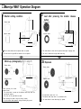
1
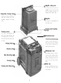
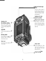
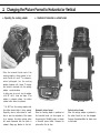
CONTENTS
Congratulations on your wise decision
to purchase this Mamiya RB67 Camera!
Perusing this manual before attempting to
use the RB67 will assist in correct camera
operation and will minimize the possibility
of malfunctions.
The Mamiya RB67 is one member of a
unique “camera family” developed by the
Mamiya Camera Company, a recognized
world leader in large-format photography.
The RB67 takes its place alongside the
famous Mamiya C Professional and the
Mamiya Press Cameras.
Versatility of the Mamiya RB67, embodying
fine performance and various capabilities,
results in a large format camera that meets
and satisfies all requirements of the advanced amateur as well as the professional
photographer, offering the means of producing top-grade pictures in all fields including general commercial, industrial,
scientific, and news photography. Its interlocking with many Mamiya Press camera
accessories further widens the range of
the RB67’s photographic application.
Specifications .............................................................................
Features ......................................................................................
Names of Parts and Outline of Operating Method ............
Operating Instructions .............................................................
Attaching and removing the lens .......................................
Shutter cocking/Shutter release button ..........................
Operating the focusing hood ..............................................
Horizontal and vertical picture format
selective operation ...............................................................
Attaching and detaching the roll film holder ...................
Loading and advancing the roll film ..................................
Multiple exposure photography .........................................
Setting the shutter speed and the aperture/Time
operation ...... ...........................................................................
Focusing knob fixing operation/ Distance scale ............
Depth-of-field/Using a tripod .............................................
Close-up photography .........................................................
Close-up photography with auto extension tubes ........
Flash photography ...............................................................
Mirror-up photography (Independent mirror release). ...
Lens hood/Carrying strap ...................................................
Changing the magnifier/Focusing hood ..........................
Changing the focusing screen/Revolving adapter ........
Lock system of the camera back (attaching system)....
Mamiya RB67 operation diagram ......................................
Special pointers in using the Mamiya RB67 Pro-S .........
Lenses ........................................................................................
Accessories ...............................................................................
1
2
6
11
12
13
14
15
16
18
21
22
23
24
25
26
28
29
30
32
33
36
38
39
40
47
q Specifications of Mamiya RB67 Pro-S
Camera Body
Type:
6 x 7cm lens-shutter type, single-lens
reflex camera
Lens mount:
Bayonet mount (with safety lock ring)
Viewfinder:
Horizontal format index mark interlocks
with revolution of revolving adapter (Vertical format based on fixing index line on
focusing screen.)
Focusing hood:
Single-action opening and closing, with
mounting lock.
Interchangeable.
Finder magnification is 2.5X.
Magnifier is also interchangeable.
Focusing screen:
With fresnel lens
Interchangeable
Revolving adapter (exclusively for Pro-S):
Vertical and horizontal positions revolving
up to full 90° rotary system, with format
indication interlocking mechanism.
By R-lock system, interchangeable with
other adapters.
By G-lock system of revolving adapter,
G-lock-type film holders are attachable.
Focusing:
Bellows extension system with rack
pinions.
Maximum extension 46mm. With focusing
knob fixing device.
Shutter and mirror cocking:
Single-action (75O) cocking by lever on
camera body side.
Others:
Accessory shoe is provided.
Shutter release button can be locked to
prevent releasing the shutter accidentally
Standard Lenses:
Mamiya Sekor 90mm f/3.8 with lens hood
Mamiya Sekor 127mm f/3.8 with lens hood
Filter screw diameter: 77mm
Aperture: Full automatic diaphragm (with
depth-of-field preview lever). f/3.8 to 32
(with click-stop for half-step aperture
settings).
With mirror-up photographing feature
(independent mirror release) device.
Shutter:
Seiko # 1 shutter
1 to 1/400 second and T (Time)
Flash synchronization:
M-X full synchronization
Pro-S 120 Roll Film Holder
Film used:
120 roll film 10 exposures; 6 x 7cm format
Actual negative size:
56 x 68.4mm
11
Film advance:
One-stroke lever film advance (After 70”
winding, can be wound in several short,
definite strokes)
Automatic double-exposure prevention.
Film wind stop automatic release.
Multiple exposure is obtainable optionally.
Film counter:
Automatic resetting type; Red index mark
disappears upon completion of film winding.
Provided with dark slide dislocation preventive device and memo clip.
Dimensions:
(Camera body with roll film holder)
Height: 5-21/32in. ( 1 4 4 m m )
Width:
4-3/32in. ( 1 0 4 m m )
Length: 8-31/32in. (228mm)
(with 9Omm f/3. 8 lens)
8-17/321n. (217mm)
(with 127mm f/3.8 lens)
Weight:
Camera body with revolving adapter and
focusing hood _..... 3 lbs., 3-2/16 oz. (1450g)
Pro-S roll film holder 15-14/16 oz. (450g)
90mm f/3.8 lens .._.. 28-6/16 oz. (805g)
127mm f/3 8 lens .._.. 26-7/16 oz. (750g)
0 Features of Mamiya RB67 Pro-S
1. Rational 6 x 7cm format
The Mamiya RB67 Pro-S is a unique, high-grade,
6 x 7cm lens-shutter type, single-lens reflex camera
developed to offer excellent picture quality and easy
handling. Mamiya feels confident that the extensive
versatility and capabilities of the Pro-S will meet and
satisfy the requirements of all photographers.
Since the 6 x 7cm format covers an area 4.5 times the 3 5 m m
format, excellent picture quality is obtainable. Especially, it demonstrates superb results in color photography. The ratio between the
length and width of 6 x 7cm formats is almost the same as that of
large photographic paper, permitting economical enlargements
without
cropping.
When designing a magazine layout, a sufficient blank space is
reserved for headlines and explanatory notes, s o that the entire
picture format can be fully utilized.
2. Single-lens reflex camera offering a bright, large finder
image
Since parallax-free focusing in the outstanding feature of the
single-lens reflex camera, speedy camera operation is possible
through brilliant, precise 6 x 7cm picture composition.
3. Excellent Mamiya Sekor lenses
Mamiya Sekor lenses boast excellent image rendition and color
balance. Various types ranging from wide-angle lenses to telephoto lenses are available.
2
These lenses are rationally grouped in series, whereby those
6. Vertical or horizontal picture format quickly changed
over with the revolving adapter
exactly adaptable to one’s particular photographing objectives are
optionally selectable with ease.
A revolving adapter is provided as a standard outfit, whereby the
vertical or horizontal picture format is promptly selected by turning
4. Lens-shutter system suitable for electronic flash
photography
the camera body back by 90°. without changing the camera position.
This is especially convenient when the camera is mounted on a
By adopting the lens-shutter system, electronic flash is synchro-
tripod.
nized with all shutter speeds, making it possible to produce highly
impressive
7. Finder format index interlocked with revolving adapter
photographs.
When the revolving adapter is turned up to 90”, horizontal format
5. Double-exposure prevention and multiexposure
devices
picture index red lines appear (or disappear), presenting proper
picture composition.
An interlocking device for double-exposure prevention is incorporated in the Pro-S roll film holder. Since this device is interlocked
8. Excellent film flatness ensured by Pro-S roll film holder
with the Pro-S body mechanism, the shutter cannot be released
Various tests have been applied to the Pro-S roll film holder to
unless the film is advanced. Also, film advance for the next expo-
stabilize film flatness. As a result, film flatness has been further
sure is impossible unless the shutter is released.
improved.
When the shutter is released, the film wind-stop is automatically
9. Camera back adapter changeable according to photographing objectives
released.
Multiple exposure photography is available simply by switching a
By changing the back adapter, depending on your photographic
lever.
objective, the range of film applications can be widened to include
120 and 220 roll films, dry plates, cut films,
3
and 70mm film.
on the photographing objectives, a checker, a rangefinder spot, a
microprism, and a cross-hair can be selected at your option.
The film holders and back adapters are very easily exchanged.
12. Excellent heat- and cold-resistant capacity
10. Unique mirror shockless mechanism
Camera component parts are capable of demonstrating their
By adopting a unique centrifuged friction governor system, the
functions within a wide temperature range from approximately 120°F
mirror functions smoothly without sensing shocks. Mirror shock,
to - 5OF (5OOC to - 2OOC).
constituting the most important problem involved in large, single-
The lens-shutter maintains accurate function, even in severe cold,
lens reflex cameras, has been solved.
and shutter speed deviation is negligible. Its resistivity to coldness
11. Large variety of finders
is superb.
A big selection of finders conforming to your photographic ob-
Although the camera operating unit grows sluggish at or below
jective are available.
15OF (-loo C), it is sufficiently capable of operating the camera until
They include a CdS finder (appropriate exposure obtainable with
the temperature drops to approximately - 50° F (-ZOO C).
Through-the-lens measuring system), a Prism finder (subjects can be
13. Mirror-up photography (independent mirror release)
possible
seen as an erect image), a CdS prism finder (former two types of
finders are combined). a Magnifying hood (easily visible and bright),
When sharp pictures are demanded, the mirror-up mechanism
a Dual magnifying hood (performs precision focusing by speedily
plays a big role. When taking a picture unhurriedly with the camera
changing the magnifier of high magnification), and a Universal
mounted on a tripod. or when photographing at slow shutter speeds
sportsfinder (permits focusing on the focusing screen after it has
or using a telephoto lens, the mirror-up operation merit is highly
been installed).
The focusing screens
effective.
are also easily exchangeable. Depending
4
14. Close-up photography through full use of bellows
characteristic features
Since the bellows can be extended up to 46mm, photographing
17. Dark slide lock for safety while carrying
A dark slide lock is provided for the Pro-S roll film holder so that
the dark slide will not slip off while carrying the holder detached
small subjects in the frame full size is possible. When auto exten-
from the camera body.
sion tubes are used, the subject can be further enlarged. When a
16. Accessory shoe
standard lens is employed, life-size (1 : 1) or larger pictures can be
photographed.
15. Single-action focusing hood
Available as a standard outfit is a collapsible focusing hood,
which can be opened and closed by single action, and which can
be shielded from extraneous light by raising the magnifier. Depending on diopter of your eyes, the magnifiers are interchangeable. A
double-lock mechanism prevents the focusing hood from accidentally slipping off.
16. Focusing knob fixing device
A focusing knob fixing device is provided so that the focusing
knob will not be moved inadvertently during close-up photography,
taking snapshots, fixed focus photography, or using a telephoto
lens.
An accessory shoe is provided for convenient use when mounting
the clip-on-type flash unit.
19. Unique safety devices
Various safety devices eliminate possible photographic failures.
20. Complete set of accessories
Availability of a complete set of various accessories further augments photographic possibilities and camera versatility.
0 Names of Parts and Outline of Operating Method
Shutter cocking lever
Nameplate
Both the shutter and the mirror are
cocked by this lever. Unless they are
set, a safety device prevents the shutter
release button from being depressed.
By slidling this nameplate, the focusing
hood can be exchanged.
Focusing hood latch
This latch prevents the focusing hood
from slipping off by carelessly moving
Dark slide
the nameplate.
When this dark slide is inserted, a
safety device prevents the shutter
release button from being depressed.
Lens mounting index mark
(red dot)
(Draw out the dark slide before taking
a picture)
-(D Bayonet ring
The lens is clamped to the camera
body by this ring. When the mirror is
not cocked, a safety device prevents
the tens from being removed.
Mirror
Distance graduation
Distance scale
Shutter release lock ring
When this ring is aligned with the
orange dot, a safety device prevents
the shutter release button from being
depressed. (Align the ring with the
white dot before taking a picture.)
Shutter release button
When the camera and the roll film
holder are not ready for photography,
a safety device prevents the shutter
from being released.
6
Magnifier setting lever
By
moving
this
l e v e r to t h e l e f t , t h e
magnifier c a n be s e t . By
down
the
magnifier
base
pressing
plate.
the
magnifier can be hooked in place
Single-action focusing hood
Opening and closing is performed by
Single action.
Extraneous
light
shield-
---a
ing design is adopted for this focusing
hood.
Magnifier
The magnifier is interchangeable with
other
diopter lenses.
Focusing hood mounting
prongs
Focusing screen
This screen is interchangeable with
various
types.
Being
interlocked
with
@
t h e revolving a d a p t e r , h o r i z o n t a l picture f o r m a t i n d e x l i n e s a p p e a r u n d e r
the
Film advance lever
a d o u b l e - e x p o s u r e p r e v e n t i v e device
screen.
prevents
the
shutter
from
being
re-
leased. Unless the shutter is released,
Carrying strap lug
the
film
cannot
be
advanced,
thus
preventing idle film advance.
Accessory shoe
Multiexposure lever
When m u l t i p l e
Dark slide storing lug
exposure
is
desired,
or when you want to release the shutter
without
loading
t h e film, it can be
achieved by moving this lever to the
front
Focusing knob
until
the
red
mark
becomes
visible.
Memo clip
Focusing knob fixing lever
By storing the separated film box cover
or
white
paper
can be entered
7
sheets
here,
memos
Slide lock for G-lock type
@ holder
Use this lock to attach and detach a
film holder. When the dark slide is not
inserted in the attached roll film holder,
a safety device prevents the holder
from being detached.
Coupling pin for multiexposure prevention
Release lever for slide lock
Coupling pin for
film wind-stop releasing
When detaching a film holder other
than the roll film holder, or when the
slide lock is locked, move the slide
lock to the left while pressing this
When the shutter is released, the film
wind-stop is automatically disengaged
by this pin, allowing subsequent film
advances.
release lever.
Light baffle
Do NOT touch this light baffle with your
fingers.
Revolving adapter
Turning this adapter up to 90D permits
change-over between the horizontal
and vertical picture format.
R-lock lever
Use this lever to attach and detach the
revolving adapter
Tripod socket
This socket is applicable to a U 1/4-inch
tripod screw. By removing the inner
socket, a tripod with a 3/8-inch tripod
~~~~~~~~~~ing base
8
Film type index (120
or 220)
Exposure counter
When the film is advanced and the
shutter is released, a red mark appears
on the side of the counter digits. When
the next film advance is completed.
the red mark disappears. The red
mark also appears while the film is
being advanced from S to 1.
Safety-catch for dark slide
When the film holder is being carried
about after detaching it from the cam-
Pro-S Outer Cassette
era body. this safety device prevents
the dark slide from accidentally slipping
off.
When the film holder is attached to the
camera body. the dark slide can be
removed automatically.
Back cover latch
Film wind-stop release lever
Film spool stud
The film wind-stop is released manually
by this lever only when the Pro-S roll
film holder is used for the Mamiya
Press.
Load a film so that the leader paper
is pulled out along the guide mark.
Spool release pin
Guide mark for leader paper
A film spool is attached and detached
by pressing down this pin.
Wind the film advance lever until e leader paper starting
mark is aligned with this mark. Af
closing the back cover,
by winding the lever several strokes, it will stop at the
first exposure position.
Take-up spool stud
Pro-S Film Insert
After inserting the take-up spool, the
leader paper is inserted on the spool.
/
8
Shutter speed ring
M-X selector
This selector is switched while depressing it.
Synchroflash
Aperture scale ring
Depth-of-field scale
terminal
Distance scale for
depth-of-field reading
Depth-of-field preview lever
Distance scale lever for
depth-of-field reading
W
Shutter release lock pin
The shutter can be released by turning
the shutter cocking pin clockwise while
pressing the lock pin.
Cocking position marks
Mirror release operating knob
To effect mirror-up photography, pull
out and turn the knob clockwise and
set it to the MIRROR-UP index, then
attach a cable release to the knob.
At first, raise the mirror and the light
baffle by depressing the shutter release
button, then release the shutter by
pressing the cable release attached to
the knob.
6D
10
Shutter cocking pin
When cocklng the shutter with a finger,
turn the cocking pin up to the red dot.
q Attaching and Removing the Lens
l
Attaching the Lens
After cocking the camera body mirror
and the lens shutter, mount the lens on the
camera body.
Cocking the Mirror of Camera body
1. Remove the front body cap from the
camera body.
2. Be sure that the mirror (3) is in the cocked, down position in the camera body,
shielding the camera film plane from exposure to light.
If the mirror is up, cock the mirror by
fully pushing down the shutter cocking lever
(1) toward the front of the camera.
_
Cocking the Lens Shutter
Attaching the Lens
1. Remove the rear cap of the lens.
2. Cock the lens shutter. Firmly turn the
shutter cocking pins (56) with your fingers.
to the red dots (A) of the cocking position
marks. Now the shutter blades are open.
* When removing your fingers from the pins,
the cocking pins will turn back to the green
1. Turn the bayonet ring (11) counterclockwise, and align the red dot on the bayonet
ring with the triangular mark at the center.
2. Mount the lens, keeping the triangular
mark aligned with the lens mounting mark
(10); then firmly twist the bayonet ring clockwise. Now, the camera and lens have been
set.
dots(B).
* If the cocking pins are not fully turned to
the red dots (A), the shutter will not be
completely cocked.
* After removing the lens from the camera
body, the shutter is always cocked.
NOTE: If the camera is placed with its back facing downward when attaching or removing
the lens, without mounting the rear body cap or the film holder, the coupling mechanism may
be damaged. Always pay attention to this caution.
12
1
•l Shutter Cocking
l
Shutter Release Button
l Disengaging the release lock of the
shutter release button
Removing the Lens
I
B
Remove the lens while the mirror and
the shutter are cocked.
Turn the bayonet ring (11) counterclockwise, aligning its red dot with the lens
mounting mark (10) on the body, and remove
the lens.
r If the mirror and the shutter are not
cocked in this instance, the lens cannot be
removed, because turning the bayonet ring
will be intercepted by action of the safety
interlock mechanism.
P r e s s d o w n t h e shutter cocking lever
(1). The shutter in the mounted lens and the
mirror in the camera body are cocked simultaneously. The lever will return to its original position by self-action.
* When shutter cocking is not completed,
the shutter cocking lever will not return to
its original position.
* Once the shutter is cocked, the cocking
lever will not move until the shutter is released by pushing the shutter release button.
Therefore, when the cocking lever will not
move. you know the shutter is cocked.
13
/i
This safety mechanism is designed to
prevent accidental release of the shutter
while carrying the camera in its case.
When the shutter release lock ring (6) is
turned and the index mark is aligned with
the white dot (A) on the body, the shutter
release button (7) can be pressed.
When the index mark is aligned with the
orange dot (B), the shutter release button
cannot be pressed.
l Releasing the shutter
When the shutter release button is
pressed, the mirror is pushed up and the
shutter is released.
* If the mirror is not cocked, the shutter
release button cannot be depressed.
* The socket inside the shutter release
button is threaded so that a cable release
or a self-timer can be easily attached.
0 Operation of Focusing Hood
_.
l
0 Raising the focusing
hood
Raising the magnifi-
er
By raising
the
back
side of the hood, the entire focusing hood will automatically spring into position.
By sliding the magnifier setting lever (19) to the
left, the magnifier will automatically pop up.
0 Folding the focusing
hood
0 Folding the magnifier
With the magnifier in
its closed position, fold
down the front and back
panels of the focusing
hood, whereby the entire
focusing hood is collapsi ble.
By pressing down the
base plate of the magnifier, the magnifier will hook
in place.
14
q
l
Changing the Picture Format to Horizontal or Vertical
Operating the revolving adapter
l
Viewfield of horizontal or vertical format
When the horizontal format mark of the
revolving adapter is facing upward, a horizontal format will result. To compose a
vertical photograph. turn the revolving
adapter clockwise until it stops. To change
from vertical to horizontal, turn the revolving
adapter counterclockwise.
In either case, be sure to turn the adapter
a full 90° until it clicks and stops. If the
adapter is stopped midway, the shutter
release button cannot be pressed.
* Do NOT turn the revolving adapter while
the shutter release button is being pressed.
Especially, when a cable release or a selftimer is used, and adjustment of the release
tip is improper, the shutter release button
will remain depressed after the shutter is
released. Always pay attention to this fact.
Horizontal picture format
When the revolving adapter is positioned at
the horizontal format, red lines appear on
the ground glass focusing screen to indicate
a horizontal picture format. Compose the
picture within the red lines.
15
Vertical picture format
When the revolving adapter is positioned in
the vertical format, the red lines disappear.
Compose the picture within the broken lines
on both sides.
0 Attaching and Detaching the Roll Film Holder
l
Removing the rear body cap
By moving the slide locks (29) on both sides
fully to the left, the cap can be removed.
* Never push the light baffle (26) on the
camera back after removing the rear body
cap. If the light baffle is pushed by force,
it will cause light leakage or a malfunction.
l
Attaching the roll film holder
1. Before attaching the holder, confirm that
the upper and lower side slide locks (29)
are on the left end of the indented portion
when viewed from behind the camera body.
NOTE:
Should either slide lock be moved to the
right while nothing is attached to the revolving adapter, the slide lock release lever (31)
will engage and the slide lock will not move.
II this happens, press the release lever (31)
and return the slide lock to the open position.
16
2. Attach the roll film holder and slide both
slide locks firmly in the direction of the arrow
mark.
(; If the slide lock of the revolving adapter
is not pushed fully in or out, the shutter will
not be released because of the shutter
locking safety device. Always operate the
slide lock securely.
* If closing the lower slide lock is neglected, the safety device of the Pro-S holder
will prevent the dark slide from being removed.
* If the dark slide is completely inserted,
or if the film is not loaded, the shutter release button cannot be pressed, leading to
picture-taking failure.
l
Detaching the roll film holder
1. Insert a dark slide in the roll film holder.
Two white lines on the side of the holder
indicate the position of the inserting slit.
2. Remove the roll film holder by sliding
both slide locks (29) in the opposite direction to the arrow mark on the slide lock.
NOTE:
Since a coupling device for
double-exposure prevention is
adapted for the Pro-S roll film
holder, the shutter cannot be
released if the film is not loaded.
* If the dark slide is not inserted, the slide
lock will be locked by the safety device,
and the roll film holder cannot be detached.
* When a dark slide is completely inserted,
the slide lock release lever (31) is automatically disengaged, and the slide locks can
be slid without pressing the release levers.
17
When desiring to release the shutter
without loading the film.
In this instance, the shutter can be released by
sliding the multiexposure lever of the roll film
holder to the front, and by setting the shutter
cocking lever and pulling out the dark slide.
+ When the dark slide is completely inserted,
the shutter release button cannot be pressed.
Therefore, either remove the dark slide or draw
it outward to a position where the entire triangular hole in the top center of the dark slide
becomes visible.
* Either operation of the multiexposure lever
or the shutter cocking can be initially conducted.
0 Loading and Advancing the Roll Film
l
Loading the film
L
1. Open the back cover by pulling out the
back cover latch, while slightly pressing the
back cover. Remove the film insert from
the holder.
x; When loading and unloading film, avoid
direct sunlight. Choose a location in the
shade.
+ Regardless of whether the roll film holder
is attached to or detached from the camera
body, loading and unloading the roll film
can be conducted in the same manner
h Use 120 roll film with the 120 roll film
holder, and 220 roll film with the 220 roll
film holder.
2. While pressing the left side spool release
pin (43), insert a new roll of film on the film
spool stud.
Load the film so that the leader paper can
be pulled out along the arrow of the leader
paper guide mark (36) In this way, the black
side of the leader paper will appear on the
outside.
+ If the black side does not appear on the
outside, reload the film, reversing the film
position.
18
3. Pull out the leader paper and insert the
tip into the groove of the take-up spool.
h Position the film so that the leader paper
winds evenly between the spool flanges;
otherwise the film may be taken up unevenly,
causing trouble.
l
Aligning the starting mark
Move the film advance lever gently, until
the starting mark (arrow) of the leader paper
aligns with the starting mark of the holder.
The film advance lever can be moved in
several short, definite strokes.
* If the leader paper is pulled too far, the
film may become fogged. Be careful not to
go beyond the starting mark (arrow).
l
Attaching the film insert
1. Put the insert into the cassette, aligning
the top side of the insert with the white dot
(A) of the cassette.
* If the film insert is attached in reverse,
the back cover cannot be closed.
2. Close the back cover and fully push in
the back cover latch while pressing the
back cover.
NOTES
1. The outer cassette of the Pro-S roll film
holder can be used for both 120 and 220
film inserts.
2. The film insert of the Pro-S roll film holder
cannot be attached to the outer cassette
of the former RB67 roll film holder.
19
l
Film winding for first exposure
By winding the film advance lever until it
stops, the figure “1” will appear in the exposure counter (39), the red mark indicating
incomplete film winding will disappear, and
the film will be positioned for the first exposure
* Unless film winding from S to 1 in the
exposure counter is completed, the shutter
cannot be released.
l
l
Film advancing
2
Dl
Exposed
Film advance
completed
(Before exposure)
1. Draw out the dark slide and release the
shutter. When the shutter is released, the
red mark appears in the exposure counter,
indicating that the film is exposed.
2. Simultaneously when the shutter is released, the film wind-stop mechanism is
automatically disengaged, and the film can
be advanced for the next frame. When film
is advanced one full frame, the figure in the
exposure counter is advanced, and the red
mark disappears.
* Unless the exposed film frame is advanced, shutter releasing is prevented by
the coupling device for double-exposure
prevention.
+ Shifting to multiple exposure photography
is possible. Refer to the next page.
* Even though film advance is completed,
the shutter cannot be released if return of
the film advance lever is hindered by your
fingers or by another object.
Film advancing and shutter cocking
* Wind the film advance lever in a slow,
steady manner to avoid film winding problems.
* Although the film advance lever cannot
be reversed until it is wound up to the initial 70” winding, it can be moved in several
short, definite strokes thereafter.
c The film wind-stop release lever provided
for the Pro-S roll film holder is to be used
when the holder is used for the Mamiya
Universal Press, or when desiring to wind
up to the film end while unexposed film
remains in the holder.
3. When you finish exposing the full number
of e x p o s u r e s , t h e s h u t t e r r e l e a s e b u t t o n
cannot be depressed and the film advance
lever will be freed. Then wind the film completely to the end of the leader paper.
l
Unloading the film
1. Open the back cover of the holder and
remove the film insert. Press the right side
spool release pin (43), remove the full spool,
then wrap and seal the film to protect it
from loosening.
2. Move the empty spool to the take-up
side. The insert is ready for reloading.
* The exposure counter automatically resets to S (start) as soon as the back cover
is opened.
c When the exposure counter shows other
than S, a film is loaded in the holder.
20
Either film advancing or shutter cocking can
initially conducted. However, the recommended sequence of these steps to be
customarily observed is: (1) film advancing,
(2) shutter cocking, and finally (3) shutter
releasing.
0 Multiple Exposure Photography
0 When desiring to wind up to the end of film while unexposed film
remains in the holder.
When the film advance lever is continuously
wound, with the film wind-stop release lever
(42) pushed to the left, the film can be reeled
up completely to its end, even though picture taking is still in progress and a film
remains unexposed.
l
Storing the dark slide
While progressing with photography, the
dark slide of the roll film holder can be
stored by inserting it into the camera body
side.
W h e n t h e multiexposure lever of the roll
film holder is moved forward, the coupling
pin for double-exposure prevention is disengaged, and whenever the shutter cocking
lever is set, shutter releasing can be repeated without limit.
* The multiexposure lever can be changed
over before or after shutter cocking, and
also before or after shutter releasing for the
first multiple exposure photograph.
* When taking multiple exposure pictures
is finished, never fail to return the multiexposure lever to its original position; otherwise, failure in taking subsequent multiple
exposure pictures will occur.
l
Memo clip
Cl Setting the Shutter Speed and the Aperture
l
Setting the Shutter speed
0 Setting the aperture
Align the desired aperture value with the
red dot on the center of the lens barrel.
* Adopted for the aperture is a fully automatic diaphragm which stops down during
shutter operation.
* The aperture can be set at full and half
click stops.
l Time Operation
1. By setting the shutter speed scale on T
(time) and releasing the shutter, the shutter
will remain open for an extended time
exposure.
2. To close the shutter, turn the shutter
speed ring toward the 1 sec. mark or press
down the shutter cocking lever about 30?
* Do not move the shutter cocking lever
until just before closing the shutter.
* When the shutter is closed by the shutter
cocking lever, the light baffle in the camera
body drops slightly lower; however, since it
is an extended time exposure, fogging over
the actual exposure does not occur.
* When the shutter is closed by the shutter
cocking lever, the lever is locked by the
reverse motion stopper and does not return
to its original position. When the shutter is
cocked by further depressing the lever, the
lever returns to its original position.
Align the desired shutter speed with the red
dot on the center of the lens barrel.
* Always set the shutter speed to the click
stop position. In-between shutter speeds
cannot be used.
c If the shutter speed is changed, after
cocking the shutter, do not turn the shutter
speed ring rapidly.
22
q
l
Focusing and Focusing Knob Fixing
Focusing
When the shutter is cocked, the mirror is
cocked simultaneously, and an image is
visible on the ground glass of the focusing
screen. By turning either the left or right
focusing knob, adjust the focus and compose the picture.
l
0 Distance Scale
Focusing knob fixing
After adjusting the focus, turn the focusing
knob fixing lever (18) forward and appropriately clamp it, whereby the focusing mechanism is secured.
* Deviation in focusing can be prevented
in this manner, when continuously taking
pictures, taking snapshots with wide-angle
lenses, close-up photographs, and using
telephoto lenses.
23
Distance from the film plane to the subject
can be determined by the distance scale
(5).
Curves on the distance scale are represented in a different color for each lens.
The figure on the distance graduation (4)
which meets the curve for the lens used
after focusing reveals the distance to the
subject.
For example, if the distance graduation and
the curve are as shown in the photo after
focusing with the 127mm lens, you can confirm that distance to the subject is 5ft. (1.5m)
by reading the graduation aligned with the
orange curve.
0 Depth-of-field
l
Viewing on the focusing screen
0 Using a Tripod
l
Using the depth-of-field scale
32 33
1. Set the desired aperture by turning the
aperture scale ring (51); then adjust the
focus.
2. Depress the depth-of-field preview lever
(47) and the depth-of-field can be observed
on the ground glass focusing screen.
When removing your finger, the lever will
return to its original position and the lens
aperture will fully reopen.
1. Turn the distance scale lever (48) and
align the figure representing the focused
distance with the center index mark on the
depth of field scale (53).
2. The two distances (on both sides of the
center index mark) opposite the same figures as the actual lens aperture on the
depth-of-field scale are the near and far
limits of depth for a given distance and lens
aperture.
For example, when photographing a subject
10 feet away with the 127mm lens at an
aperture of f/16, objects from about 8 to 13
feet will be in focus.
For maximum picture sharpness the use of
a sturdy tripod is recommended. Insert the
tripod screw into the tripod socket (32) at
the bottom of the camera.
When a tripod with a 3/8 inch tripod screw
is used, remove the inner socket by turning
the tripod socket counterclockwise with a
coin or similar disk inserted in the slots of
the socket. The standard tripod has a 1/4
inch tripod screw and can be used for this
camera in conjunction with the inner tripod
socket.
l
Tripod Mounting Base
The tripod mounting base (33) at the bottom
of the camera is for attaching a quick shoe.
If you keep a quick shoe on your tripod
head, the camera can be quickly and easily
mounted on it.
24
c Close-up Photography
l
l
Exposure compensation for close-up photography
Maximum close-up photography table
(with bellows fully extended)
The lens-to.-subject distance represents the distance of the su
edge of the lens barrel.
When the lens is extended for close-up photography, and distance between the lens and
the film plane increases beyond normal,
image brightness on the film plane decreases, requiring an increase in exposure.
To adjust the exposure, refer to the exposure
compensation scale on the camera body.
1. After adjusting focus on the subject, read
the exposure compensation value obtained
on the exposure compensation scale.
For example, assume that focus was adjusted with the 127mm lens and the result
was as shown in the photo.
Seek the same pattern in the bottom column
as the pattern where side panel lines meet
the 127mm lens scale. The numerical value
of that pattern (+ 1 in this case) is the exposure compensation value.
2. Compensate the exposure by changing
either the shutter speed or the aperture.
When the exposure compensation value is
+ 1, open the aperture one stop, or slow the
shutter speed 1 step. For 0.5 step compensation, use the half-stop aperture scale
settings.
For example, if your exposure meter shows
an exposure setting of (1/60 sec. at f/16), it
must be adjusted in the case of the + 1
compensation value to (1/30 sec. at f/16) or
(1/60 sec. of f/11).
* When using the CdS finder for the
Mamiya RB, exposure need not be compensated, since the meter reads actual
exposure directly.
25
from the front
* When using the 50mm and 65mm lenses
closer than 3 1/4 ft (1 meter), it is necessary
to use a lens aperture of f/16 or smaller to
obtain satisfactory lens performance.
* Graduations on the upper side of the
distance scale represents the bellows extension values (mm).
This scale is used to obtain exposure compensation values for close-up photography
with extension tubes. (Refer to the next
page.)
0 Close-up Photography with the Auto Extension Tubes
7. Since it will decrease resolving power
due to exceeding life-size, do not use the
auto extension tube with the 50mm lens.
Close-up photography table
1. Distance indicates the distance from the
front edge of the lens barrel to the subject.
2. The figures in the left column of the
close-up table indicate no bellows extension. The figures on the right indicate when
the bellows is extended to the maximum
(46mm).
l Attaching and detaching the auto extension tubes
Attaching and detaching the auto extension
tubes is accomplished in the same manner
as with the lens. When initially mounting a
lens to the extension tube, cock both the
lens and the tube.
* The auto extension tubes couple with
the automatic diaphragm of the lenses.
NOTES
1. For exposure compensation, refer to the
following table. Reading of the exposure
compensation scale differs from that when
not utilizing extension tubes.
2. For close-up photography, we recommend independent mirror-releasing prior to
each actual photograph. This omits or minimizes any residual camera body movement
due to mirror action.
3. When photographing through the extension tubes, use as small an aperture as
possible.
4. When photographing in the 6 x 7 size,
if the 127mm lens is used, minimal or no
corner vignetting will occur, however, when
using lenses other than the 127mm lens with
two extension tubes (No. 1 and No. 2), the
possibility of some vignetting in the four
corners of the picture may occur. When
using only one extension tube, no vignetting
will occur with any lens.
5. When photographing with the Polaroid
Land film pack, corner vignetting increases
due to the larger picture size, however a
6 x 7cm portion in the center of the photo
will be essentially clear of vignetting.
6. Use only one auto extension tube No. 1
for the 65mm lens.
26
l How to determine the exposure compensation value
1. After focusing the lens, read the extension amount through the bellows extension
scale (A) on the top of the distance scale.
2. Find the compensation value by the
“Bellows extension scale/Exposure compensation value” located on the right side
of the close-up photography table. For
example, assume that 127mm lens is focused after combining it with No. 2 auto extension tube. If the extension amount reads
35mm by the bellows extension amount
scale, it is understood that the compensation value is + 2 steps by the scale located
on the right side of the close-up photography table. In this case, increase exposure by setting the shutter speed dial two
steps slower or by opening the aperture by
two steps.
f W h e n u s i n g t h e CdS f i n d e r f o r t h e
Mamiya RB. exposure need not be compensated, since the meter reads actual
exposure directly.
27
0 Flash Photography
l
Connecting the cord
b M-X selection
l
Determining the aperture
The aperture setting for flash photography
is determined by dividing the guide number
of the bulb or the electronic flash unit by
the distance.
(Guide number] 56
-(Aperture setting] 8
(Distance to subject) 7
Connect the cord of the flash unit to the
synchroflash terminal (46).
Flash Synchronization Table
The M-X selecting lever is internally locked
to prevent unintentional switching of the
mode.
When switching the M-X selector, move
the lever to the right or left, until it reaches
the end while pressing the lever against the
lens barrel.
The letter X or M, which indicates the contact type, should appear in the window.
* When employing electronic flash, set the M-X selector to X to synchronize flash at any shutter speed.
t When M-class flash bulbs are used, set the M-X selector to M to
synchronize at any shutter speed.
* When F-class flash bulbs are used, set the selector to X and photograph at 1/60 sec. or a slower shutter speed.
28
’
0 Mirror-up Photography (Independent Mirror Release)
In mirror-up photography, previously release
the mirror and operate only the lens shutter
at the moment of taking the photograph.
This mirror-up photography is recommended
When a tripod is employed and the shutter
is released at slow speed, when taking
close-up photos, or when using a telephoto
lens, where avoidance of even a negligible
shock is desired, or when curtailment of
even a negligible time lag between pressing the shutter release button and the
shutter opening is desired
l Preparations
1. Pull out the independent mirror release
operating knob (50) and turn it clockwise,
and align the red dot on the knob with the
MIRROR UP indication dot.
2. Screw a cable release into the female
screw socket in the knob center.
3. By fully pressing down the shutter cock.
ing lever, cock the shutter and the mirror.
The sequence of foregoing procedures
1, 2, and 3 can be optionally altered.
l Photographing
1. On pressing the shutter release b u t t o n,
the mirror and the light baffle will snap up,
but the shutter will not be released.
2. R e l e a s e t h e s h u t t e r w i t h t h e c a b l e
release. (When you do not have a cable
release, simply return the mirror release
Operating knob to the original position to
release the shutter.)
3. By pulling out the knob and turning it
counterclockwise, the mirror-up mechanism
can be disengaged.
* Even when picture-taking is switched
to mirror-up photography, the mirror is set
at each shutter cocking. Accordingly, it is
possible to confirm the image on the finder
screen prior to taking each picture.
d For this type of photography, an ideal
forked mirror-up cable release is available
as an optional accessory.
NOTE:
Unless the mirror release operating knob
is returned, the camera will remain set for
mirror-up photography. In this case, the
film will not be exposed even when the
shutter release button is pressed.
0 Lens Hood
0 Carrying Strap
lAttaching
This lens hood can be used commonly for the 90mm,
127mm. 180mm. and 250mm lenses.
1. Screw the attachment ring into the front of the Ions
mount.
2 . Pull the folded rubber hood straight out. using it as the
hood for the 127mm. 180mm. and 250mm lenses.
3. For the 90mm lens, fold the hood back halfway
While holding both sides of the
strap attaching metal, slide the
attaching metal toward the
hanging direction, after fitting
and pressing the round hole o n
the metal back side to the lug
for strap on the camera body.
To fold the hood, pull it straight out, place the hood on a
flat surface, and push down from the top to easily fold the
lens hood
You can also leave the hood on the lens for portability by
pushing back and turning out the hood while it is attached
to the lens.
A filter can be screwed in between the lens and the hood,
or in front of the lens hood.
30
Note:
Always attach and use the strap
so that it and the strap attaching
metal are straight.
When changing the strap hanging direction, always reattach
the strap.
* If the strap attaching metal is
connected to the accessory
shoe side in reverse, detaching
will be difficult.
l
Detaching
Holding the camera by
the strap
l
l
Three hanging positions
Depending on the attached
position of the strap, there are
three hanging positions for the
strap as illustrated in the photos.
Since the strap attaching lug is
not rotary, the strap will never
become twisted.
T O detach the strap, slide the
a t t a c h i n g m e t a l in r e v e r s e
direction to attaching, while
slightly raising the leaf spring on
the attaching metal with a finger
tip.
After adjusting the length of the
carrying strap, pass your left
hand through the strap, and
while stretching the strap down
from your neck, hold the camera with your left hand. The camera can be held lightly, easily,
and securely in this manner.
0 Magnifier
lChanging
the magnifier
While holding both side panels of the focusing hood to prevent lowering of the magnifier base plate, turn the magnifier counterclockwise, and at the point where the white
dot on the magnifier becomes aligned with
the while dot on the base plate, remove the
magnifier.
After aligning the magnifier white dot with
the base plate white dot, mount another
magnifier by turning it clockwise.
* In addition to the standard (-1.3) diopter
lens, available are +1, 0, -1, - 2, and -3
diopter lenses (six in total].
0 Focusing Hood
0 Attaching
lDetaching
While pressing the focusing hood latch (9),
slide the nameplate (8) to the right as viewed
from the front, and remove the focusing hood
while slightly raising its front portion.
32
Insert the two prongs (21) on the back of the
hood into the slots on the camera body, and
while pressing the hood front portion toward
the camera body, return the nameplate to
Its original position. The latch will pop out
and the hood will be locked automatically.
Cl Focusing Screen
Five types of easily exchangeable focusing
screens are available to meet various photographing applications.
0 Attaching and detaching
First remove the focusing hood, then take
out the focusing screen while holding both
sides.
To attach it, hold each side and insert the
focusing screen into the top of the camera
body and press down lightly.
q Revolving Adapter
To detach the revolving adapter, pull out
and down on the R-lock lever (28) at the
bottom of the camera body.
To attach the revolving adapter to the camera body, face the white index dot on the
adapter toward the top of the camera body,
and fully push the R-lock lever up, while
firmly pressing the adapter toward the camera body.
NOTE:
When the focusing screen has been detached, do not touch the picture format indicating red dot on the side of the camera body.
33
I When attaching the revolving adapter,
press it firmly so that it is attached tightly
and never comes loose. If the adapter is
attached somewhat loosely, it will cause
light leakage.
x: The revolving adapter of the Pro-S is
not applicable to the former RB67.
* Since the revolving adapter for the former
RB67 has no interlocking mechanisms (such
as a double-exposure preventive device,
a horizontal picture format marking device,
and a safety device f o r p r e v e n t i n g t h e
shutter from releasing when the dark slide
is i n s e r t e d ) . d o n o t e m p l o y it w i t h t h e
Pro-S bbdy.
When desiring to pull out the dark
slide of the roll film holder which has
been removed from the body
Releasing the lens shutter which has
been removed from the body
Shutter testing when the film is
loaded
When the roll film holder for the Pro-S is
removed from the body, the safety device
prevents its dark slide from being pulled out
carelessly or accidentally. However, if you
desire to pull it out, it can be pulled out by
using your fingernail tip to press the dark
slide lock release lever (40) on the bottom
of the outer cassette.
It is advisable to release the shutter when
the lens is not to be used for a long period.
To release a lens shutter which is removed
from the camera body, turn the cocking
pins (56) clockwise, while pressing the
shutter lock pin (55) with a finger. The
cocking pins should be turned all the way;
do NOT leave the pins turned only halfway..
When the shutter is cocked, the dark slide
is slightly pulled out (approx. 1/4 in.) and
the shutter release button is pressed, the
shutter can be released without exposing
the film in the roll film holder to light. This
operation can be utilized for shutter testing
prior to photographing.
* When pulling out the dark slide. stop pulling at a
point where the entire triangular hole on the dark slide
becomes visible. If the shutter is released when the
dark slide is pulled out beyond that hole, the film will
be exposed to light.
* When the shutter is released, a red mark appears
on the exposure counter.
* When taking the first photograph subsequent to
this test, cock the shutter in the multiexposure condition, and pull out the dark slide. For taking pictures
following the first one, restore the multiexposure lever
to its normal position and continue photographing.
34
When the lens is installed on the camera while the mirror and the
shutter are not set.
Lens installation is possible even if the
mirror and/or the shutter are/is not set;
however, operation shown in the table must
be followed to obtain a normal set condition.
In this case, do not pull out the dark slide of
the film holder until the camera is set to a
normal condition.
Mirror condition
fl
However, when the shutter release button
is necessarily pressed with the roll film
holder attached, as shown in “1” of the table,
move the multiexposure lever forward and
slightly pull out the dark slide, and then
press the shutter release button.
; Shutter blade condition
&-q
F
Operation
q&
Opened or Closed
35
Cl Lock System of the Camera Back (Attaching System)
Pro-S Revolving adapter
Pro-S Roll film holder for Mamiya RB
(and G-lock system holders)
Polaroid Land pack film holder
model 2
M adapter (horizontal)
Mamiya’s unique lock system is adopted
for the camera back of the Mamiya
RB 67 (as shown in the diagram) to
widely and systematically utilize various
Mamiya a c c e s s o r i e s . W e h a v e n a m e d
these locks the R-lock, G-lock, P-lock,
and M-lock.
As seen in the diagram, the R-lock is
standard for the Mamlya RB 67 camera
b o d y . C o n s e q u e n t l y , in principle, an
adapter having an R-lock must first be
attached to the camera body.
After
that, attach the selected film holder
through the adapter indicated on the
diagram.
Roll film holder
for Mamiya Press
(and M-lock system
holders)
36
1
1
I
I
When the roll film holder for the former RB67 is
used on the Pro-S camera body.
When film holders for the Mamiya Press are
used for the Pro-S camera body.
Since the former roll film holder is not equipped with a
coupling device for double-exposure prevention, operate it in the same manner as if it were mounted on the
former RB67 camera body.
When using these holders, mount each holder on the
camera body back through a P-adapter and an Madapter.
These holders can be handled in the same manner as
if they were mounted on the Mamiya Press.
When photographing in a horizontal format, the horizontal format marking lines (red lines) do not appear on the
finder. Accordingly, refer to the red lines which appear
when the revolving adapter is attached, and mark the
format with a piece of tape on the ground glass focusing
screen.
When the roll film holder for the Pro-S camera
body is used for the former RB67 camera body.
Although the coupling device for double-exposure
prevention does not function in this case, the film windstop device is automatically released when the shutter
is released, and the film is ready for winding.
Other operating methods are the same as those when
using the former RB67 camera body.
When Polaroid Land pack film is used with the
Pro-S camera body.
When using the Polaroid Land pack film holder,
P-adapter to mount it on the camera body back.
Compose the picture through full view of the
glass focusing screen. In this case, the actual
size will become approximately 2 3/4 x 2 3/4 in. (7 x
When the roll film holder for the Pro-S is used
for the Mamiya Universal Press.
Use in the same manner as when the roll film holder
for the former RB67 is mounted on the Mamiya Universal
Press.
When the film wind-stop release lever (42) is moved to
the left, a red mark appears on the exposure counter,
the wind-stop is released, and the film is ready for
winding.
-1
37
use a
ground
picture
7cm).
0 Mamiya RB67 Operation Diagram
r
1
2
Shutter setting condition
Just after pressing the shutter release
button
Shutter blade
Shutter blade
Aperture blade
Aperture blade
/-\
( j
‘Y
k
.
L
l
Both the shutter blade and the aperture blade are opened.
The mirror and the light baffle are lowered to the set position.
l
l
The shutter blade is closed and the aperture blade begins
The mirror is raised and the light baffle starts rising.
3
Mirror-up photography
Exposure
Shutter blade
Shutter blade
Aperture
(1) When pressing the shutter
release button:
. The shutter blade is closed and the aperture blade stops down to a
preselected aperture.
. The mirror and the light baffle are raised.
(2) When releasing the shutter, using the mirror-up release:
l Only the shutter blade operates, closing after being fully o p e n e d .
blade
. The light baffle is raised to its limit.
. The aperture blade stops down to a preselected value
l The shutter blade is closed after being fully opened.
38
,&,
stopping down.
0 Special Pointers on Using the Mamiya RB67 Pro-S
Various safety interlock devices are provided for the
Mamiya RB67 Pro-S to eliminate failures through carelessness. When the shutter is not released, or when the
lens or the roll film holder cannot be removed, do not
hastily concluded that this indicates a camera malfunction.
Ascertain the following conditions. The Instruction Manual
pages covering these situation are indicated in parentheses.
l
Shutter release button cannot be depressed
l
Lens cannot be removed
Press down the shutter cocking lever. Set the mirror and the
shutter. (P.13)
(1) Is the roll film holder loaded with a roll of film and has the film
been advanced to the first exposure?
When shutter releasing is desired without loading film, by sliding
the multiexposure lever forward and setting the shutter cocking
lever and pulling out the dark slide, the shutter can be released.
(P.17)
l
When mounting the film holder, the slide lock cannot
be moved
While pressing the slide lock release lever, move the slide lock
to the left. (P.16)
(2) After the shutter was released during ordinary exposure (not under
multiple exposure), did you advance the film?
Advance the film with the film advance lever.
l
(3) Is the mirror set?
Set the mirror by pressing down the shutter cocking lever.
Roll film holder cannot be removed
After inserting the dark slide, operate the slide lock.
(4) Was the dark slide drawn out?
Draw out the dark slide.
l
(5) Is the shutter release button locked?
Regarding the mirror release operating knob
Normally align the knob with the red dot. When it is aligned with
the MIRROR-UP index mark, and merely the shutter release button is pressed, the mirror and the light baffle will operate, but no
image will be recorded on the film. (P. 29)
Turn the shutter release lock ring counterclockwise and align it
with the white dot. (P.13)
(6) Is the revolving adapter turned up to the click stop position?
Turn the adapter until it stops with a click. (P.15)
(7) Has the slide lock on the revolving adapter stopped halfway?
Move the slide lock up to the position where it stops. (P.16)
39