1
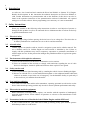
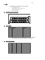
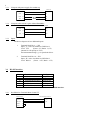
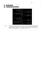
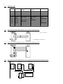
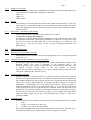
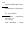
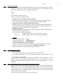
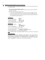
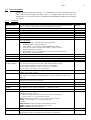
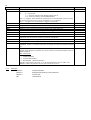
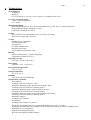
Operating instruction ComuCont Dual ComuCont Dual documentation_eg.DOC Date: 28.03.2001 15:56:00 Seite 3 Contents 1 INTRODUCTION ...................................................................................................................................................... 4 2 SAFETY INSTRUCTIONS........................................................................................................................................ 4 2.1 ELECTRICAL SAFETY.................................................................................................................................................. 4 2.2 AIRCRAFT SAFETY ..................................................................................................................................................... 4 2.3 ENVIRONMENTS WITH EXPLOSIVE SUBSTANCES ........................................................................................................... 4 2.4 SAFETY ON THE ROAD ................................................................................................................................................ 4 2.5 NON-IONIZING RADIATION ......................................................................................................................................... 4 2.6 ELECTRONICS IN MEDICAL EQUIPMENT ....................................................................................................................... 4 2.7 PRECAUTIONS IN THE CASE OF LOSS/THEFT OF THE CELLULAR ENGINE AND THE SIM CARD ........................................... 4 3 PORT .......................................................................................................................................................................... 5 3.1 PORT PLAN OF THE SCREW TERMINALS ........................................................................................................................ 5 3.2 POWER SUPPLY .......................................................................................................................................................... 5 3.3 RS 232 / V24 INTERFACE ........................................................................................................................................... 5 3.3.1 V24-port with power supply for readout top ..................................................................................................... 6 3.3.2 V24-port to PC Sub-D 9- pole without Handshake............................................................................................ 6 3.3.3 Inputs............................................................................................................................................................... 6 3.4 RS 485 INTERFACE .................................................................................................................................................... 6 3.4.1 Port RS485-to Terminal Memo Count NT......................................................................................................... 6 3.5 CL / TTY INTERFACE ................................................................................................................................................ 7 3.5.1 Wiring plan of the CL / TTY interface .............................................................................................................. 7 3.5.2 active CL / TTY................................................................................................................................................ 8 3.5.3 Port ComuCont CL 2-wire interface active to meter interface passive ............................................................. 8 3.5.4 Port ComuCont CL 4-wire interface active to meter interface passive ............................................................. 8 3.5.5 Port ComuCont CL 2-wire interface active to Memo Count NT devices interface passive ................................ 8 3.5.6 passive CL / TTY.............................................................................................................................................. 9 3.5.7 Port ComuCont CL 2-wire interface passive to meter interface active ............................................................. 9 3.5.8 Port ComuCont CL 4-wire interface passive to meter interface active ............................................................. 9 3.6 LEDS / SIM-CARD PLUG .......................................................................................................................................... 10 3.6.1 SIM-card........................................................................................................................................................ 10 3.6.2 Function of the LED’ s.................................................................................................................................... 10 4 INSTALLATION...................................................................................................................................................... 11 5 COMUCONT DUAL-CORE.................................................................................................................................... 12 5.1 INFORMATION ON OPERATION .................................................................................................................................. 12 5.1.1 Starting the ComuCont Dual .......................................................................................................................... 12 5.1.2 Initializing of the radio-module...................................................................................................................... 12 5.1.3 Field strength display .................................................................................................................................... 12 5.1.4 Display of a radio link ................................................................................................................................... 13 5.1.5 Backup........................................................................................................................................................... 13 5.1.6 Data format –Adjustment of the interface...................................................................................................... 13 5.2 ADDITIONAL FUNCTIONS.......................................................................................................................................... 13 5.2.1 Restriction of call acception (Time slot)......................................................................................................... 13 5.2.2 Code protection against unauthorized access on terminals............................................................................. 13 5.2.3 Selection of the net operator .......................................................................................................................... 13 5.2.4 Automatic recall ............................................................................................................................................ 13 5.2.5 Call-note........................................................................................................................................................ 14 5.2.6 11bit Data transmission ................................................................................................................................. 14 5.3 WORKING MODE CONDITIONS OF THE DEVICE ............................................................................................................ 14 5.3.1 Disconnect-Transparent-Mode....................................................................................................................... 14 5.3.2 Connect-Login-Mode ..................................................................................................................................... 15 5.3.3 Connect-Transparent-Mode ........................................................................................................................... 15 5.3.4 Connect-Parameterization-Mode / Disconnect-Parameterization-Mode ......................................................... 15 5.4 REQUIRED SETTINGS/INFORMATION FOR THE CONTROL STATION ................................................................................ 16 5.5 PARAMETERIZATION ................................................................................................................................................ 17 5.5.1 Commands ..................................................................................................................................................... 17 5.5.2 Messages ....................................................................................................................................................... 18 6 TECHNICAL DATA................................................................................................................................................ 19 4 1 Introduction As radio core, the ComuCont Dual contains the WaveCom WMOi3 or Siemens TC35 Engine. Besides the descriptions in this instruction the technical description on WaveCom WMOi3 is valid. Further information on parametrization and on the functions of this device can also be found in the operation instruction of the parametrization software PARACOM. All required settings are set in this software. Direct programming is not necessary or is not recommended. 2 Safety instructions Please pay attention to the following safety instructions in order to avoid injuries of persons or damages on this product as well as on connected devices. Maintenance has to be done exclusively by qualified maintenance-staff. 2.1 Electrical safety Danger high voltage. Before opening, the device has to be set voltage-free. The device has to be orderly earthed before connections are set to the In- and Out-terminals. 2.2 Aircraft safety Cellular engines can interfere with an aircraft’ s navigation system and its cellular network. The use of WMOi3 and TC35 Cellular Engine on board aircraft is forbidden by law. Failure to comply with this prohibition may lead to temporary suspension or permanent cancellation of cellular engine services for the person who infringes this prohibition and/or to legal action against said person. 2.3 Environments with explosive substances a) Users are advised not to use the device in automotive service stations. b) Users are reminded of the necessity to comply with restrictions regarding the use of radio devices in fuel depots, chemicals plants and locations where explosives are ignited. 2.4 Safety on the road a) It is not permitted to signal incoming calls by sounding the vehicle’ s horn or flashing the lights. b) Drivers are advised not to use the hand-held microphone or the telephone handset while their vehicle is in motion, except in the case of emergency. Use the handsfree facility to speak only if it does not divert your attention from the traffic. 2.5 Non-ionizing radiation As it is the case with other mobile radio transmitters, operating personnel are advised to use the device in the normal ope-rating position only in order to ensure optimum performance and safety. 2.6 Electronics in medical equipment Radio transmitters, including cellular engines, can interfere with the operation of inadequately protected medical devices. Please address all questions to a doctor or the manufacturer of the medical device. 2.7 Precautions in the case of loss/theft of the Cellular Engine and the SIM card If your ComuCont DUAL, your SIM card or both go missing, notify your network operator immediately in order to avoid misuse. Seite 3 Port At the modem, there is a block with 36 screw terminals • for the interface RS232 • for the interface CL (TTY) 2 and 4 wire • for the interface RS485 and • for the power supply 3.1 Port plan of the screw terminals 3.2 Power supply Pin No. 9 11 12 21 22 23 24 35 36 NOTE: 3.3 Function Pin Type PE PE L1 Net N Net PE PE PE PE PE PE PE PE +24V /20mA unregulated out power GND (24V) GND power A voltage between 90V –260V AC/DC (50/60Hz) can be applied to the modem. The power input is typically 3.5VA (5VA max.) RS 232 / V24 interface Pin No. 1 2 3 13 14 15 25 26 27 NOTE !! Function Pin Type PC-port SUBD-9-pole Vcc / +5V out power /IN1 DTR in 4 GND Gnd power 5 IN2 RTS In 7 RXD Out 2 TXD in 3 CTS Out 8 Bridges 31-32 and 33 –34 have to be removed of! 5 6 3.3.1 V24-port with power supply for readout top ComuCont Dual 3.3.2 1 +5V GND 13 GND RXD 25 RXD TXD 26 TXD V24-port to PC Sub-D 9- pole without Handshake ComuCont Dual 3.3.3 3.4 readout top +5V RS232 to PC Sub-D no Handshake GND 13 GND RXD 25 RXD TXD 26 TXD Inputs The device desposes of two additional inputs. 1. Terminal block Pin 2. = /IN1 Input: „ L“ -active in relation to GND Pin 13 Level: TTL (Umax. +5V; Rmin. –0,3V) (internal in 2.2k pull up to VCC) ExcitationAnsteuerung e.g. via open drain driver. 2. Terminal block Pin 14. = IN2 Input: „ H“ -active in relation to GND Pin 13 Level: RS232 (Umax. +15V; Rmin. – 15V) RS 485 interface Pin No. Function Pin Type 7 +5V / 20mA out power 8 485+ (B) in/ out 19 GND/Potential balance GND power 20 485- (A) in/ out 31 GND GND power 32 485/enable in NOTE !! Bride Pins 31-32 for the activation of the RS485-interface. 3.4.1 Port RS485-to Terminal Memo Count NT ComuCont Dual Terminal (Memo Count NT) GND 19 GND 485- (A) 20 485- (A) 485+ (B) 8 485+ (B) RS485 active 31 32 Seite 3.5 3.5.1 CL / TTY interface Wiring plan of the CL / TTY interface Note: In the following tables, the functions of the Pins are indicated according to the definition of a data transmission unit (DUE). If, when indicating the function (section function ..) significance is put in brackets, this is meant to be the terminal description of the data terminal to be connected (DEE –e.g. PC, Memo Count NT, ..). 7 8 3.5.2 active CL / TTY Pin No. 4 5 6 16 17 18 28 29 30 33 34 NOTE !! 3.5.3 Function Function 4Dactive TX-24V (TX+) RX-24V (RX+) +5V RX+ (RX-) Br. 17-18 Function 2Dactive Nc RX (TX) +5V Br. 16-29 Br. 17-30 Nc TX (RX) Pin Type TX_I+ out RX_I+ out +5V out power RX_C out RX_E out RX_G GND power TX_A TX+ (TX-) in TX_K Br. 29-30 in TX_G GND power GND GND GND GND power CL/enable CL/enable CL/enable in Bridge Pins 33-34 for the activation of the CL-interface. Port ComuCont CL 2-wire interface active to meter interface passive Up to 8 meters can be connected. * to VDEW-specification 2.0 3.5.4 Port ComuCont CL 4-wire interface active to meter interface passive 3.5.5 Port ComuCont CL 2-wire interface active to Memo Count NT devices interface passive Memo Count NT No. 1 Memo Count NT No. 2 Memo Count NT No. n D1/C9 R- D1/C9 R- D1/C9 R- D2/C8 R+ D2/C8 R+ D2/C8 R+ D3/C7 T- D3/C7 T- D3/C7 T- D4/C6 T+ D4/C6 T+ D4/C6 T+ D5/C11 S1+ D5/C11 S1+ D5/C11 S1+ D6/C10 S1- D6/C10 S1- D6/C10 S1- ComuCont Dual 5 24V Note: 30 Gnd Dx = Memo-Count NT 1/2-duct 17 RX- Cx = Memo-Count NT 4-duct 29 TXCL select 33 16 RX+ 34 28 TX+ max. number of devices: n=4 Seite 3.5.6 passive CL / TTY Pin No. 4 5 6 16 17 18 28 29 30 33 34 NOTE !! Function Function 4DFunction 2DPin Type passive passive TX_I+ nc nc out RX_I+ Nc nc Out +5V +5V +5V out power RX_C RX+ (RX-) Br. 16-29 out RX_E RX- (RX+) RX (TX) out RX_G Nc Nc GND power TX_A TX+ (TX-) TX (RX) in TX_K TX- (TX+) in TX_G Nc Nc GND power GND GND GND GND power CL/enable CL/enable CL/enable in Bride Pins 33-34 for the activation of the CL-interface. 3.5.7 Port ComuCont CL 2-wire interface passive to meter interface active 3.5.8 Port ComuCont CL 4-wire interface passive to meter interface active 9 10 3.6 LEDs / SIM-card plug 3.6.2 Function of the LED’ s LED 1: On: The device is registered in the radio-network, e.i. the device can be reached. Blink: The device is not (yet) registered in the radio-network. LED 2 and 3: These LEDs indicate a default, the field strength of the radio-net or a modem-radio connection. LED 2 Off Blinks On On On Off 3.6.1 SIM-card Open the device lid to plug in the SIM_card. The radio-modem is installed perpendicular to the motherboard. Plug in the SIM-card into the holder labeled SIM. To open the holder device, please push the key beside it. LED 3 Off Off Off Blinks On On Meaning Field strength < 8 Field strength < 10 Field strenghth < 14 Field strength < 20 Field strength >=20 A modem radio connection exists Note: The field strenth can achieve a value between 1 and 31. From field strength 5 onwards, the radio-modem logs into the net. LED 0 This LED indicates a default Note: The Program PARACOM displays default messages in plain text after the readout of a device. Seite 4 Installation For installation, proceed as follows: 1. Plug in the SIM-card 2. Plug in/Installation of the radio antenna 3. Plug in the serial ports to the terminal 4. Apply a voltage of (90-260 V AC/DC (50/60 Hz) 5. Parameterization of the device via the serial digital trunk interface by using the parameterization software NOTE: On distribution of the devices, the internal Goldcap for the coverage of the clock module is not loaded. Therefore, time-display is lost in the case of net-off. Thus, on distribution, the device indicates a default displayed by blinking of the two upper diodes. Only after 5 –15 minutes of coverage being applied upon, time and date remain saved during a short net-off-period. After approx. 3 hours of coverage being applied upon, the Goldcap has reached the point where tiding over a period of 30 days is possible. If there is a lack of coverage via the Goldcap during a net-off, the time is pre-adjusted to 00:00 o´clock on 01.01.1999 and a default is indicated. At the next net-on/off, in case that the Goldcap meanwhile had been loaded sufficiently, the default message will be deleted. Cancellation also results from parameterization of date or time. NOTE: Parameterization of the device is saved on an EEPROM. If there is a lack of coverage, this does not effect these parameters. 11 12 5 ComuCont Dual-core The functionality of the WaveCom WMOi3 Engine is extended via the ComuCont Dualcore. The core consists of a 8051 processor, an internal clock buffered via Goldcap, an EEPROM for the storage of the parameters and a RAM of 32 KB to buffer the overflow during data transmission to the control station. 5.1 Information on operation The clock-module is buffered via a GoldCap. The parameters are saved on an EEPROM and are independant on buffering. During the initial installation or in case of long-term net-off (long-term storage) the ComuCont Dual may indicate a default during parameterization or at the clock-module. These defaults are removed by parameterization or synchronization (also see 4. Installation). Further defaults are registered in relation to the release (PIN-input) of the radio-module. Defaults are indicated via blinking of the two upper LEDs. By readout of the device via the parameterization-software PARACOM, defaults may be displayed in plain text. 5.1.1 Starting the ComuCont Dual When power is applied upon, primarily the Hardware is initialized and checked on defaults. At the same time, the radio-module is started and initialized. Then the SIM-card is checked on its status, i.e. queried on its access-code. Hereby the following options are differentiated: 1. The PIN-number is deactivated in the card Also if a PIN was parameterized, no PIN-number is transferred to the card. 2. The card asks for the PIN-nummer If a PIN-number had been parameterized, it will be transferred up to twice to the card . If this twice does not result in a positive acknowledgement, the ComuCont Dual is set on default (LED2 and 3 blink). Now, the PIN-number may again be parameterized correctly. However, if it is wrong again, the card will disable and may only be activated by entering the PUK (NOTE!! At each restart or each parameterization, the PIN will be transferred twice. I.e. at this twice transmission the PIN will be disabled!). 3. The card asks for the PUK-number or does not response The device is set on default (LED2 and 3 blink). The PIN-number is no longer transferred to the card. Thus, only 1PUK-trail (of 10) is spend at maximum. The card may only be enabled manually by entering the PUK (command AT+CPIN=PUK-number, new PIN CR). The login into the radio-net results automatically. If the ComuCont Dual must not be reachable, this automatic will be deactivated. Initialization and checking may take up some time. Therefore, the device is only reachable serially or via the radio-net after several seconds. 5.1.2 Initializing of the radio-module Initialization, i.e. a reset of the radio-module is implemented at the following times: 1. After net-on 2. After parameterization 3. After link via the radio path 4. In parameterized time intervall (since the last initialization) 5. If the radio-module does no longer response serially 5.1.3 Field strength display Approx. every 3 seconds, signal-field strength is queried and displayed via LEDs 2 and 3 (see 3.6.2 Function of the LED’ s). If data are transferred, however, this query is disabled (at minimum for 30 seconds). Seite 5.1.4 Display of a radio link As soon as a radio-modem-link is established, the function of the field strength display will be deactivated. The modem-link is displayed via the LEDs: LED3: on LED2: off LED1: blinks 5.1.5 Backup For a backup via the radio path, the protocols RLP (Radio Link Protocol) or V.42bis are taken. The use as well as the backup via the net-fixed line between net operator and control station are dependant on the net operator and on the control station (Adjustment with or without V.42bis). 5.1.6 Data format –Adjustment of the interface In the ComuCont Dual, data format via the radio path is pre-fixed to 8 data bits, no parity and 1 Stop bit. The interface to the data terminal (terminal multiplexer) can be adjusted via PARACOM. If transparent transmission is desired, the adjustment of 8 data bits, no parity and 1 stop bis has to be selected via PARACOM. Thus, a device sending e. g. on 7 data bits, even parity and on 1 stop bit, the parity bit will be jointly transferred (Exception 11bit transmission). 5.2 Additional functions 5.2.1 Restriction of call acception (Time slot) The restriction of call acceptance can be activated completely or for a certain period per day (time from –to). 5.2.2 Code protection against unauthorized access on terminals By entering a 8 digit code, the unauthorized access on the connected data terminals can be protected against. This code is equivalent to the ComuCont Dual – ID. If this protection is active, the code is queried in case of a call acception. Only if this code is entered correctly, circuit switch to the data terminal is possible. NOTE! This protection is only effective, if a code for parameterization of the device was entered, too. Otherwise this code can be read. 5.2.3 Selection of the net operator Reguarly, indication of the net operator is not necessary. Only in areas where several net operators are located (threshold areas), this indication could be necessary. Normally, the radio-module automatically selects the net operator in the region that indicates the highest signal power. In the ComuCont Dual, it is optionally possible to indicate a net operator permanently or preferentially, also if the signal power is lower. If the net operator is indicated permanently, the device only logs into this net, i.e. in case that the signal power of the net operator is too low, login into the net is disabled. In this case the device is not reachable! In case that the net operator is indicated preferentially, but the signal of which is too low, the device logs into an external net. Approx. every 14 minutes the system checks wether the device logged into the net of the preferential net operator or if this net is generally available. 5.2.4 Automatic recall Automatic recalls can be initiated in certain intervalls. The following intervals are available daily weekly - on a certain day of the week monthly –on a certain day of the month. The recall is passed through a control station parameterized in the device. If the link is not established sucessfully (e.g. busy) the number of the next register is selected. 13 14 5.2.5 Call-note As soon as the code protection against unauthorized access to the data terminals is activated, a call-note can be made. At the call-note, instead of the code during Login, the command for call-note including indication of the telephon register number 0-3 of the device, as well as a 8-digit acknowledgement recognition is transferred. Then the ComuCont Dual automatically hangs up and, at the earliest after 5 seconds, starts the recall to the telephon number of the selected register. 5.2.6 11bit Data transmission Besides the standard settings of 10 bits per signal (8.1,None or 7,1,Odd) signals of 11 bits can be transferred, too. Thus, the settings such as 8 Data, 1Stopbit and Even Parity to the data terminal are possible. The transmission via the radio path/permanent net path is however only possible with 10bits. Therefore reaching 11bit signals without Parity with 8.N,1 are retransmitted by the radio-module. 5.3 Working mode conditions of the device Information on the below indicated descriptions: Disconnect: There is no phone connection to another modem. Connect: There is a connection to another modem. Transparent: Data are directly (with conversion of the Baudrate and data-, Stop-, and Paritybits) retransmitted. Parameterize: All data are intercepted and evaluated by the processor. 5.3.1 Disconnect-Transparent-Mode After the net-on, the ComuCont Dual is in the Disconnect-Transparent-Mode, which means, that all signals transferred to the local digital trunk interface are automatically retransmitted to the integrated modem of the ComuCont. In the same way, the Modemresponse is again transmitted via the interface. Thus, the modem can be additionally parameterized with AT-commands. This function may only be done by trained personnel! The parameters (Baudrate, Data bits, Parity, Stopbits) of the serial digital trunk interface can be variable adjusted (see parameterization-mode). Note: In the Disconnect-Mode no codes are active. Via the signal sequence „ $$$“ , which has to be entered within one second and a signal stop of more than one second before this sequence, you get into the DisconnectParameterization-Mode. Seite 5.3.2 Connect-Login-Mode If the code for the protection against unauthorized access to the data terminals is activated, the device is in this mode after a successful connection set up via a call. In this case the device retransmits the signals to the calling control station Login: as command for entering the code. There are 3 options to change the mode: 1. Change-over to the Connect-Transparent-Mode If now the 8-digit code (ComuCont –ID) with closedown <CR> is transferred to the device, this results into a change-over into the Connect-Transparent-Mode. 2. Change-over into the Connect-Parameterization-Mode Instead of the code, you can change-over into the Connect-Parameterization-Mode via the signal sequence $$$ (see Disconnect-Transparent-Mode). When closing down this Mode, the device returns into the Connect-Login-Mode. 3. Starting of call-notes When the device receives the call-note command, it hangs up automaticallly and after a short stop starts the required recall. Call-note command: !Sncccccccc<CR> n: Telephon number register 0-3 of the ComuCont Dual cccccccc: Recall recognition in case of a call to the control station Example: ComuCont Dual transfers: Login: Control station transfers: !S1abcdefgh<CR> ComuCont Dual transfers: OK <CR><LF> (in case of a default there will be no response) After the OK, the device hangs up and starts the recall to the telephon number from register 1. The device returns with the text : COMUDUAL/abcdefgh At a recall, the device is in the Connect-Transparent-Mode. 5.3.3 Connect-Transparent-Mode This mode is reached, - via a telephone connection by a recall (Call-note or recall automatic) - via a telephone connection by a call, if the Transparent-Mode is not protected by a code or - via the Connect-Login-Mode. In this mode, the control station can directly communicate with the terminal. Via the sequence „ $$$“ (see Disconnect-Transparent-Mode) one can change-over into the Connect-Parameterization-Mode. However, this is only recommended with a 8.1,None connection. 5.3.4 Connect-Parameterization-Mode / Disconnect-Parameterization-Mode Regularly this mode is reached via the signal sequence „ $$$“(see Disconnect-TransparentMode). In this mode, the following indicated commands can be transferred to the ComuCont Dual. In case of remote parameterization, however, writing as well as reading of the ComuCont-ID is disabled when the parameterization-code is activated. Disabling can be opened via the command L. Exit the mode via the command Q (see parameterization). 15 16 5.4 Required settings/Information for the control station The control station has 3 possibilities to transfer data to or from a data terminal connected to a ComuCont Dual: 1. No code for the Transparent-Mode is active The ComuCont Dual reacts like a modem customary in trade. No special commands or settings are necessary. 2. The code for the Transparent-Mode is active a. After receipt of the signal sequence, the control station transfers Login: the 8-digit code. If a wrong code is entered, the ComuCont Dual stops the modem connection. b. The control station requires a recall (see call-note). No code is required, however the correct telephone register number (0-3). Example to 2a Set ComuCont-ID: 0815-abc ComuCont Dual transfers: Login: Control station transfers: 0815-abc<CR> ComuCont Dual transfers: OK <CR><LF> (in case of a default there will be no response) Example to 2b ComuCont Dual transfers: Login: Control station: !S1abcdefgh<CR> ComuCont Dual transfers: OK <CR><LF> (in case of a default there will be no response) The ComuCont Dual hangs up and recalls after a short stop ComuCont Dual transfers: COMUDUAL/abcdefgh<CR><LF> ComuCont Dual changes over into the Transparent-Mode Note: In telephone register 1 the telephone number of the control station has to be deposited! General Information Concerning the Baudrate, the adjustment of the interface at the control station is independant from the adjustment of the data terminal. However it is important to see to it, that no overflows occur owing to too big Baudrate-differences. Among others, this can be avoided by Handshake-procedures. For the adjustment of the data bits and the Parity, please read paragraph 5.1.6 Data format –Adjustment of the interface Seite 5.5 17 Parameterization Parameterization is done line-oriented, i.e. a command line has to be closed down by CR. Thte ComuCont Dual requires the entry with a „ :“ -Prompt at the start of the line. The settings have to be saved via the SAV-command in the EEPROM. Otherwise the changes are rejected. 5.5.1 Commands Command-Format WNAxxxxxxxx Effect Sets the 8-digit ComuCont-ID / Transparent-code. This ID is transfered to the control station in case of a timer-controlled recall (COMUDUAL\comu-id) Reading of the ComuCont-ID. RNA Setting of the 4-digit PIN of the SIM-card. With 4 blanks, the PIN is deleted. WNPxxxx Reading of the 4-digit PIN (4 blanks = deactivated) RNP Sets the 8-digit ComuCont-ID into transparent-mode -code active (n=1)/inactive (n=0) WDLn Reading of the activation recognition RDL Readout of Firmware Version: CWAV0A00 V1.00 RVE Reading of the current default number (Decimal number) RER BIT Information 0 Parameter default –parameterized with PARACOM 1 EEPROM-default –Hardware-default 2 Clock-default –set time with PARACOM/Hardware-default 3 PUK query/no answer from the radio-module –release via PUK 4 Parameterized PIN is unvalid. 5 Radio-Module queries for PIN, however this was not yet parameterized 6 RAM-default –Hardware-default Sets the internal time WZEhh:mm:ss Output of the current time in the next line in format hh:mm:ss RZE Setting the current date of the real-time-clock WDATT:MM:JJ Output of the current date in the next line in format TT:MM:JJ RZE WCO<baud>,<db> Sets the settings of the serial digital trunk interface. Example: WCO9600,8,1,N For <baud> the values 300, 600, 1200, 2400, 4800, 9600 are possible ,<stop>,<parity> For the number of data bits <db> the values 7, 8 are possible. For the number of Stop bits <stop> the values 1,2 are possible For the <parity> the values N, E, O are possible. Output of the current communication-adjustment in the next line in format RCO <baud>,<db>,<stop>,<parity>. Reading of the radio-module-reset intervalls in minutes (0-9999). In the indicated RMR intervall the radio-module is restarted (RESET) –then the module re-logs into the radio-net. Setting of the radio-module-reset intervall in minutes (0-9999). If the value 0 is WMR indicated, the function is de-activated. Setting the number of ringing signals (n=1-9) before call acception WS0n Reading of the set number of ringing signals RS0 Setting of a time domain (from –to), within which the ComuCont Dual accepts a call. WRAhh:mmThe domain can also surpass midnight (e.g.: WRA23:00-02:00) hh:mm Output of the current call-acception-time domain in format hh:mm-hh:mm RRA WRRwMMhh:mm Sets the time and intervall at which the ComuCont Dual automatically starts a recall (00000:00 : recall is inactive). w : indicates the day of the week on which the recall is to be realized 0=Mo, 1=Tue a.s.o.; * does not mean weekly MM: Recall-day of the month [1..31]; ** does not mean monthly hh:mm: Recall-hour[0..23] –recall-minute [0..59] Example: WRR*0112:00 (recall on each first of the month at 12:00) WRR2**23:00 (recall on each Wednesday at 23:00) WRR***06:30 (recall daily at 06:30) Output of the recall-intervall in format wMMhh:mm (see above). RRR Sets the number of recall trails (xx=0..30). WRVxx Between these recalls, the system pauses for 1minute, respectively. Default value 00000000 blank 0 00:00:00 01.01.99 9600,8,1,N 421 1 00:00-24:00 00000:00 1 18 Command-Format RRV WHAx RHA WHIxxxxx RHI RHH RHL WCHx RCH WDPpwd Lpwd SAV Q WPRESET 5.5.2 Effect Output of the number of recall-trails in the next line. Selection of the radio-net x: 0 = any operator 1,3 = operator indicated with WHI angegeben wurde 2,4 = local-net resulting from the IMSI-number For x= 1,2 applies: if the desired net-operator does not exist/disabled, another net may be selected. The desired net is being searched for every 14 minutes. For x = 3,4 applies: The indicated net is logged-in exclusively. Readout of the radio-net indication (see WHA) 5-digit location-dialing code of the desired net operator (MCC + MNC) Readout of the 5-digit defined location-dialing code Readout of the 5-digit local-net-location-dialing code of the SIM-card Readout of the 5-digit location-dialing code of the logged-in net Activate RTS/CTS-Handshake at the digital trunk interface (x=1) or de-activate (x=0) Reading of the Handshake settings Sets a code for parameterization via a modem. The code pwd can have 6 marks at maximum. For de-activation, WDP is transferred without pwd. Realizes a Login with code pwd (only necessary via modem) Backup of the current settings on EEPROM Exits from the parameterization mode and activates the settings from the backup in EEPROM. If there is a modem connection, the settings are only activated after hanging up. This command resets all settings (PRESET). Then, the internal RAM, the EEPROM and the clock-module are checked. The result is delivered in decimal numbers (also see RER-command) BIT Information 0 no meaning 1 EEPROM-default 2 Clock-module-default 6 RAM-default –Hardware-default NOTE!! All parameters are reset, i.e. so far parameterization loses ist effect. The PRESET-values only become correctly active at the next net-on. Messages Default 1: Default 2: Default 3: OK: invalid command default during backup of the parameters invalid code command ok Default value 0 Blank 0 Blank Seite 6 Technical data Serial interfaces V24/RS232 RS485 or CL (TTY 20mA) 2- or 4-wire - active or passive - according to EN 61107 - - - - Coverage of external devices + 24V / 20mA (unregulated) +5V / 20mA Modem functionalilty Radio-Module WMOi3 or TC35 for 900/1800 MHz nets (e.g. D1, D2, E) - initial coverage 2W Data transmission with 9.600 Baud (V.42bis) Commands according to AT-Hayes System RTC-real time clock with running-reserve of 35 days via Goldcap Processor for control (8031 Derivat) Version Sealable device –installation as field set-up housing on top hat rail on counter standard lid or with three-point fixing The terminals are suited for 2.5mm² - Housing Impact resistant plastic –protection type IP50 Temperature resistant up to 65° C Operating coverage 90 to 260 V AC/DC, (50/60 Hz) - Line voltage Typically 3.5 VA. (5 VA max.) - Environmental temperature -10°C to +50°C - Storage temperature -25° C to +65° C - Humidity 5% to 90% R.H.(non-condensing) - Specifications / Standard HF-irradiation: according to IEC/EN 61000-4-3, 3V/m. Interference immunity against electro-static discharge, ESD: according to IEC/EN 61000-4-2, intensity grade 3. Interference immunity against quick transient sizes, burst: according to IEC/EN 61000-4-4, intensity grade 4. Interference immunity against energy-strong transient sizes, Surge: according to IEC/EN 61000-4-5, intensity grade 3 Interference transfer: according to EN 55022/B Net interrupt: according to EN 61000-4-11, 100%/1s The device corresponds to the CE –regulations (EN60950, 89/336/EC, 73/23/EC) Furthermore the indications and regulations of the Technical description for WaveCom WMOi3 and SIEMENS TC35 are applicable. Production according to ISO 9002 We reserve the right for technical changes. 19