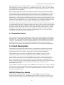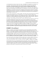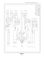
1
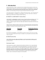
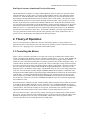
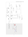
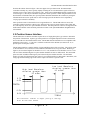
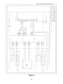
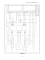
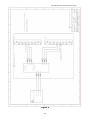
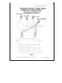
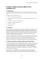
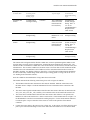
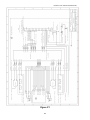
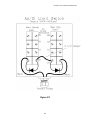
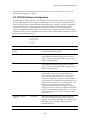
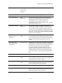
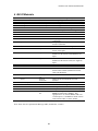
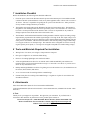
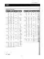
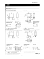
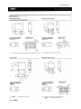
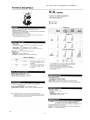
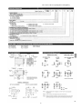
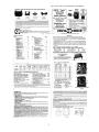
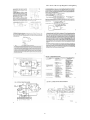
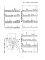
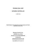
RC2K90INT-1, RC2K90INT-2, RC2KINT
RC2000 Antenna Interface Box
V. 1.10
Contents Subject to Change
6/28/01
Research Concepts, Inc.
5420 Martindale Road
Shawnee, Kansas 66218-9680 USA
PH: (913) 422-0210; FAX: (913) 422-0211
WWW.ResearchConcepts.COM
RC2000 Antenna Controller Interface Box
1. Introduction
This document describes a family of products that allow an RC2000 antenna controller to interface with
antennas powered by either 90 or 180 volt DC motors (RC2K90INT-1 and RC2K90INT-2) or other motor
types (RC2KINT). The RC2000 antenna controller is designed to interface directly with antennas which
employ 36-Volt DC motors (8 amps maximum) and single phase pulse type position sensors. When the
RC2000 is used with antennas powered by other types of motors an interface box is required.
Three unique interface box configurations are available from Research Concepts. These configurations are
designated RC2K90INT-1, RC2K90INT-2, and RC2KINT. All versions of the interface are housed in
NEMA 4 type enclosures that are suitable for outdoor mounting.
RC2K90INT-1 and RC2K90INT-2 Interface Boxes
The RC2K90INT-1 and RC2K90INT-2 interface boxes are designed to interface with either 90 volt or 180
volt DC motors. The RC2K90INT-2 interface box employs a pair of DC motor drive modules and
supports simultaneous movement about the antenna’s azimuth and elevation axis. The RC2K90INT-1
interface box employs a single DC motor drive module and simultaneous azimuth and elevation movement
is not supported.
The DC motor drive modules used in these interface boxes provide dynamic braking of the motors and are
available in either 120 or 240 VAC input voltage versions. The following table gives the maximum motor
horsepower as a function of AC input voltage and motor voltage.
Input Voltage
120 Volts AC
240 Volts AC
220 Volts AC
Motor Voltage
90 Volts DC
90 Volts DC
180 Volts DC
Maximum Motor Horsepower
1 1/2 horsepower
1 1/2 horsepower
3 horsepower
When ordering an RC2K90INT-1 or an RC2K90INT-2 interface box please specify the AC line voltage,
the DC motor voltage and the motor horsepower, and whether two-speed operation, described later in this
section, is required.
RC2KINT Interface Box
The RC2KINT interface box consists of the 2K90INT-2 circuit board mounted in a NEMA 4 type box.
The circuit board provides uncommitted relay contact closures to activate motor drive control devices
provided by the user.
Polarization Control
The RC2000 antenna controller is designed to directly interface with three wire servo type polarization
control devices. An optional daughter board (designated RC2KPOL) can be installed on most RC2000
models which provides an interface to a 24 volt DC polarization control motor (400 ma) which uses a
potentiometer for position sense feedback. The RC2KPOL daughterboard is compatible with many Seavey
Engineering rotating feeds. All of the interface boxes described here provide contact closures which can
be used to provide polarization control for antennas which use motors other than 24 volts DC. For these
applications it is necessary to install the optional RC2KPOL daughter board in the RC2000 antenna
controller. Please contact Research Concepts for more information.
2
RC2000 Antenna Controller Interface Box
Dual-Speed Antenna Azimuth and Elevation Movement
The RC2000 antenna controllers use a pulse width modulation scheme to obtain slow speed movement
when interfaced to 36 volt DC motors. This pulse width modulation scheme is not compatible with the
interface box. When the RC2000 A and C model antenna controllers are used with the interface boxes
described here, antenna azimuth and elevation movement occurs at fixed speed(s) - the controller’s pulse
width modulated speed control system must be disabled (from the keypad). These speed(s) are set by the
installer via potentiometers located in the RC2K90INT Interface Box. With Dual-Speed interface boxes,
two-speed motion is implemented by using the RC2000A’s (former) polarotor output to specify the speed.
The polarotor output becomes the speed control bit when the ROTATING FEED PRESENT? CONFIG
Mode item is set to 1. If polarization control is required with a dual speed interface box, the RC2KPOL
option must be the polarization control entity. The RC2000 / 2K90INT system does support Polarotorservo type polarization control schemes but only when operating with a single-speed interface box. A
special version of the RC2000C code implements the dual-speed option.
2. Theory of Operation
The two issues which must be addressed to interface an RC2000 controller to a large antenna is the
application of power to the antenna motors and sensing of the antenna's position. Polarization control may
also be an issue. Applying power to the antenna will be addressed first.
2.1 Controlling the Motors
Figure 1 shows a schematic representation of a single axis (in this case azimuth) of the antenna control
system. The output of the RC2000 on the AZ1 and AZ2 terminals will be +/- 36 volts. When AZIM CCW
(east in the northern hemisphere) movement is specified, AZ1 will have the higher voltage, and when
AZIM CW (west in the northern hemisphere) movement is specified, AZ2 will have the higher voltage. In
a similar fashion, when down movement is specified, EL1 will be at the higher voltage, and when upward
movement is specified, EL2 will be at the higher potential. When east movement is specified, current will
flow out of the AZ1 terminal of the RC2000, through the dropping RESISTOR, R. The purpose of the
dropping resistor is to match the output voltage of the RC2000 (nearly 40 volts) to the voltage rating of the
relay coils. The current then continues through STEERING DIODE D1, through the east RELAY COIL,
through the EAST LIMIT SWITCH, through the WEST LIMIT SWITCH, and back into the AZ2 terminal
of the RC2000. Current flowing through the EAST RELAY COIL will activate the relay and close the
EAST CONTACT CLOSURE. This will configure the POWER CONTACTOR to move the antenna in
the east direction. When east current flows STEERING DIODE D2 keeps current from flowing through
the west RELAY COIL.
When the antenna is within the east limit, the EAST LIMIT SWITCH remains closed. When the east limit
is reached, the EAST LIMIT SWITCH will open. When this occurs, STEERING DIODE D3 will keep
east current from flowing, but will allow west current to flow. West movement limiting is accomplished in
a similar fashion. Note that limit switches are not required. The RC2000 series controllers maintain
logical limits based on the position count. Limit switches are pretty cheap insurance, however.
The circuit shown in Figure 1 shows the relay contacts activating power contactors that control the motor
drive power. The key part of the circuit outlined in Figure 1 is the use of the AZ1 and AZ2 outputs of the
RC2000, the dropping resistor, the relays, steering diodes, and the limit switches to generate contact
closures which can be used to control the antenna’s azimuth motor.
3
RC2000 Antenna Controller Interface Box
4
RC2000 Antenna Controller Interface Box
Note that the scheme shown in Figure 1 does not support slow speed movement. RC2000 antenna
controllers normally vary motor speed by rapidly switching the 36 volt antenna drive signals off and on which gives an average voltage of less than 36 volts. If this pulse width modulated signal is applied to the
circuit of Figure 1, the relays would chatter and produce erratic operation. When using the interface boxes
described here with the RC2000, slow speed operation should be disabled on the controller by setting the
azimuth and elevation slow speed codes to 254. The single speed of the interface box is adjusted by
varying a pot on the drive module(s).
Slow speed movement via the interface box is supported however. The RC2000 software can use the
controller’s polarotor output to control a relay which provides a pair of contact closures (NO, COM, and
NC) which specify fast or slow speed antenna movement. Note that polarotor control is not supported with
the RC2000 controller in this mode but polarization control via the optional RC2KPOL daughterboard is
still available.
2.2 Position Sensor Interface
The RC2000 series of antenna controllers require the use of single phase pulse type sensors to determine
the position of the antenna. A pulse type sensor produces a rectangular shaped waveform as the antenna
moves about the axis associated with the sensor. The RC2000 antenna controllers are not compatible with
quadrature pulse sensors. 5.7 volts DC is available on the back of the RC2000 (at connector J1-11) to
provide power for the pulse sensors.
The RC2000 controllers count the number of rising and falling edges of the waveform. The position count
is decremented for east (or down) movement and incremented for west (or up) movement. Referring to
Figure 2, the waveform's high level should be 4.5 to 5.7 volts, and the low level should be 0.0 to 0.5 volts.
The waveform's minimum high or low pulse duration should be at least 10 milliseconds. This means that
pulses less than 10 milliseconds long may not be detected by the antenna controller. The maximum
number of counts from the antenna's east limit to its west limit should be less than 65000. Remember, each
rising edge and each falling edge of the sensor's output waveform is a separate count.
H i g h l e v e l Wa v ef o r m
d u r a t i o n g r ea t er t h a n
1 0 m Sec
L o w l ev el Wa v e f o r m
d u r a t i o n g r ea t er t h a n
1 0 m Sec
5 .7 V
4 .5 V
Vo l t s
0 .5 V
0 .0 V
tim e
Th e m a x i m u m n u m ber o f
m u s t b e l ess t h a n 6 5 0 0 0 .
ed g e s ( r i s i n g o r
Fi g u r e 2.
5
f a llin g)
RC2000 Antenna Controller Interface Box
Many large antennas use a sensor attached directly to each of the fundamental axis of the antenna. The
sensor used may be a synchro, potentiometer, or a quadrature pulse encoder. A pulse type sensor attached
to the fundamental axis of the antenna is not suitable for use with RC2000 antenna controllers. The reason
for this requires a bit of explanation.
When a rising or falling edge is detected on the antenna controller's sensor input, the antenna controller
must determine whether to increment or decrement the position count. Since single phase pulse sensors are
used, the antenna controller must determine which way the antenna was last commanded to move, and
decrement or increment the count accordingly. With a pulse sensor connected directly to the antenna's
fundamental axis, when the antenna vibrates back and forth due to wind, the pulse sensor produces a steady
stream of pulses. The antenna controller will increment or decrement the count depending on which way
the antenna was last commanded to move. In reality the antenna is just vibrating in the wind and not really
moving. The result of this is an error in the position count maintained by the antenna controller.
The antenna controllers are designed to work with 36 volt actuators. With these actuators the pulse sensor
is connected directly to the motor. The motor typically drives either a worm or screw type gear, which will
not transmit wind motion from the antenna back to the motor. Therefore, no false counts are recorded by
the antenna controller. By placing a Hall-effect sensor on the shaft of the antenna motors drive, a similar
decoupling of wind vibration is achieved. On certain models of the RC2000 it is possible to disable the
accumulation of position pulses when the antenna is not commanded to move (or is in a coast interval
immediately following the release of the motor drive lines).
2.3 Polarization Control
If the polarization is controlled with something other than a polarotor, then an interface for a polarization
motor is necessary. Many popular rotating feeds use a 24 VDC motor with a potentiometer as the position
feedback device. These feeds can be driven directly by the RC2000 with the RC2KPOL option (ordered
separately). The RC2KPOL drive provides greater than 200mA @ 24 Volts for these feeds. In the event
that a high voltage DC or AC motor is used to drive the polarization axis, a scheme similar to that
described above for controlling the azimuth and elevation motors can be used with the RC2KPOL option
3. Circuit Description
The interface boxes described in the this document use a common printed circuit board to generate the
contact closures (described in the previous section) required to control the azimuth, elevation, and (if
needed) polarization axis of the antenna. That printed circuit board is designated 2K90INT-2.
The RC2KINT interface box consists of the 2K90INT board in a NEMA 4 enclosure. The user is
responsible for using the contact closures generated by the circuit board to control the antenna.
The RC2K90INT-1 interface box uses a single KBPB motor drive module. The motor drive module
accepts AC line voltage and contact closures produced by the 2K90INT-2 circuit board and generates the
drive voltage used to power the motors. The motor drive voltage produced by the KBPB motor drive
module is routed back onto the circuit board where a latching relay directs the current to either the azimuth
or the elevation axis. Simultaneous azimuth and elevation movement is not possible with the
RC2K90INT-1 interface box.
The RC2K90INT-2 interface box employs a pair of KBPB motor drive modules. Line voltage is connected
to both motor drive modules and each motor is directly connected to a motor module - motor drive voltage
does not pass through the 2K90INT-2 circuit board. With the RC2K90INT-2, simultaneous azimuth and
elevation movement is permitted.
KBPB DC Motor Drive Module
The RC2K90INT-1 and RC2K90INT-2 interface boxes employ KBPB DC motor drive modules
manufactured by KB Electronics, Inc. The KBPB motor drive modules use SCRs to rectify the AC line
voltage and control the voltage DC delivered to the armature of the motor being controlled. The KBPB6
RC2000 Antenna Controller Interface Box
125 is designed for use with 120 volt AC line voltage. The KBPB-225 is designed for use with 240 VAC
line voltage. These motor drive modules also provide speed control, electronic current limiting, IR
compensation, and dynamic braking. A resistor which is installed in the KBPB called the Plug-In
Horsepower Resistor matches the KBPB’s IR compensation and current limit characteristics to the DC
motors used on the antenna. When a KBPB is ordered the horsepower of the motors with which the drive
module will be used should be specified so that the correct horsepower set resistor can be installed. When
the KBPB-225 is used with 90 volt DC motors a modification is performed to the motor drive to limit the
voltage applied to the motors to 90 volts DC. This modification is described in section 4.4. The Operating
instructions for the motor drive module(s) are included with the operating manual for the RC2K90INT-1
and RC2K90INT-2 interface boxes.
The line voltage is applied to the L1 and L2 terminals. The polarity of the voltage applied to the motor and
the operation of the dynamic brake are controlled by the S1, S2, and S3 connections. When the S2
terminal is not connected to either the S1 or S3 terminals the motor drive is in the brake mode. When S2 is
connected to S1 voltage is applied to the armature of the motor (via the A1 and A2 terminals). When S2 is
connected to the S3 terminal a voltage of the opposite sense is applied to the motor.
The armature voltage (and the motor speed) can be varied by connecting a potentiometer across the P1 and
P3 terminals and applying the voltage present at the wiper of the potentiometer to the P2 terminal.
Alternatively, the speed can be controlled by connecting the P2 terminal to the S4 terminal and using the
potentiometer located on the KBPB module labeled AUX (or R14) to vary the speed. When the interface
box is used with the RC2000D dual speed azimuth and elevation control is available by connecting the
terminals on the interface board labeled P1_KBPB1, P2_KBPB1, P3_KBPB1 to the P1, P2, and P3
terminals, respectively, of the KBPB. When used with controllers other than the RC2000D the S4 and P2
terminals of the KBPB are connected together and the azimuth and elevation speed is controlled via the
AUX (R14) pot (for this configuration only single speed azimuth and elevation movement is available).
2K90INT-2 Circuit Board
Figure 3 is a schematic of the 2K90INT-2 circuit board. The circuit which includes relays K2 and K3
generates the contact closures required to control the azimuth axis as described in figure 1 above. The
azimuth +/-36 volt output of the RC2000 is applied to the terminals labeled AZ1_CTL and AZ2_CTL. The
east and west limit switches and their associated steering diodes are connected to the terminals labeled
AZLIM1 and AZLIM2. If limit switches are not used a jumper can be connected between the AZLIM1
and AZLIM2 terminals. When east current flows relay K2 activates which in turn connects the terminal
labeled S2_KBPB1 to the terminal labeled S1_KBPB1. In a similar fashion, when west current flows relay
K3 is activated and the terminal labeled S2_KBPB1 is connected to the terminal labeled S1_KBPB1.
The elevation control circuit consisting of relays K5 and K6 operate in a manner identical to the azimuth
circuit. The control signals are applied via the EL1_CTRL and EL2_CTRL terminals. The contact
closures associated with these relays are available at terminals S1_KBPB2, S2_KBPB2, and S3_KBPB2.
The polarization control circuit is implemented with relays K7 and K8. The control inputs for this circuit
are generated by the an RC2KPOL board installed in the RC2000 antenna controller and are applied to the
circuit board via the P1_CTL and P2_CTL inputs. The contact closures associated with polarization
control are available at connector J8. The user is responsible for using these contact closures to realize a
polarization control scheme for the polarization motors used on his or her antenna.
7
RC2000 Antenna Controller Interface Box
Figure 3
8
RC2000 Antenna Controller Interface Box
The circuit associated with latching relay K4 is used by the RC2K90INT-1 interface box. With the
RC2K90INT-1 interface box a single KBPB DC motor drive module is present and the latching relay is
used to route the motor drive current to either the azimuth or elevation axis. The relay will not be included
with the RC2K90INT-2 and RC2KINT model interface boxes. When an azimuth control input signal is
applied to the AZ1_CTL and AZ2_CTL inputs the K4 relay coil labeled ‘LATCH_AZ’ on the schematic is
energized and the inputs labeled A1_KBPB and A2_KBPB (connected to the A1 and A2 outputs of the
KBPB) are connected to the azimuth motor via the AZMOT1 and AZMOT2 outputs. The diode bridge
formed by diodes D6, D7, D8, and D9 insures that an azimuth control signal of either polarity will result in
a unipolar voltage being applied to the ‘LATCH_AZ’ coil of the relay. When the azimuth control signal
generated by the RC2000 is removed the latching relay stays in the ‘azimuth’ position.
In a similar fashion, when an elevation control input signal is applied to the EL1_CTL and EL2_CTL
inputs the ‘RESET_EL’ coil of the K4 relay is energized and the relay contacts are configured to connect
the A1_KBPB and A2_KBPB contacts to the elevation motors via the ELMOT1 and ELMOT2 outputs.
The diode bridge formed by D12, D13, D14, and D15 allows an elevation drive current of either polarity to
activate the ‘RESET_EL’ coil of the relay. When the elevation control input is removed the relay will stay
in the ‘elevation’ position until an azimuth input is applied. It is necessary to use a latching relay to select
the azimuth or elevation axis to support the dynamic braking capability of the motor drive module. If a
non latching relay were used, when the control input is removed (for one of the two axis) the relay would
switch while the motor is braking (and current is flowing). This would defeat the braking action and
generate noise as the relay contacts open with a load applied.
The RC2000D antenna controller supports dual speed azimuth and elevation movement when used with the
interface box. With the RC2000D software the controller’s polarotor control output may be used to
activate relay K1 on the 2K90INT-2 board. This relay provides a pair of speed control channels which can
be used with either the KBPB DC motor drive module (in the RC2K90INT-1 or RC2K90INT-2 interface
boxes) or a user supplied controller (with the RC2KINT interface box) to obtain dual speed azimuth and
elevation movement. When used with other members of the RC2000 controller family only single speed
azimuth and elevation movement is available.
The K1 relay is powered with 5.7 volts DC via the terminals labeled +5.7V and Return. 5.7 volts is
available at the back panel of the RC2000 antenna controller. To activate the relay (and select high speed
movement) 5 volts is applied to the terminal labeled Pulse. Resistor R1 is a dropping resistor on the base
of transistor Q1 to limit the voltage at the base to approximately 0.7 volts. When Q1 turns on the relay is
activated. The relay provides two speed control channels. Each channel consist of a pair of
potentiometers. Only a single channel will be considered. For the KBPB1 speed control channel, the
KBPB1_FST and KBPB1_SLO pots (designated P2 and P3, respectively) are connected to the P3_KBPB1
and P1_KBPB1 terminals. When fast speed is selected the voltage at the wiper of the KBPB1_FST
terminal is presented to the P2_KBPB1 terminal. When slow speed is selected the voltage on the wiper of
the KBPB1_SLO pot is connected to the P2_KBPB1 terminal. If contact closures are required rather than
switched potentiometer wipers the potentiometers can be replaced with jumpers.
Diodes D1, D4, D5, D10, D11, D18, D19, D22, and D23 are used to suppress the back emf induced in the
relay coils when the relays are de-energized. These are sometimes referred to as ‘buck diodes’.
The connection of the 2K90INT-2 circuit board to the KBPB DC motor drive module(s) varies with the
type of interface box (RC2K90INT-1 or RC2K90INT-2) as well as the type of controller (the RC2000D
software supports dual speed azimuth and elevation movement, other models of the RC2000 controller
only support single speed azimuth and elevation movement). The wiring schematics for the various
configurations are given in figures 4, 5 and 6.
9
RC2000 Antenna Controller Interface Box
Figure 4
10
RC2000 Antenna Controller Interface Box
Figure 5
11
RC2000 Antenna Controller Interface Box
Figure 6
12
RC2000 Antenna Controller Interface Box
4.0 Heater Option
A heater option has been developed for the RC2K90INT series of interface boxes. The KB Electronics
KBPB Drive used in RCI 90VDC interface boxes has a low temperature rating of 0 C. This is inadequate
for most environments. The heater option, designated RC2K90INT-HTR adds a maximum of 100W of
heating to the box allowing a no-wind low temp of –50F for the std. 12 x 12x 6 inch interface box.
The Heater option uses a SPST thermostat that turns on at 32°F. Two 115VAC 54W heating pads are
wired in series for 230VAC –rated boxed and parallel for 115VAC –rated boxes. The heating pads are
attached to the underside of the baseplate with special high-temperature adhesive. the thermostat and
heaters are protected with a single fuse in line with the Hot AC input.
5. Installation / Setup
This section describes the installation and setup of the interface box.
5.1 Mechanical Installation
The standard interface box is housed in a 12” by 12” by 6” (height x width x depth) NEMA 4 enclosure.
NEMA 4 enclosures are suitable for outdoor use. The interface box is designed to be mounted vertically
on the antenna kingpost. The mounting holes are suitable for 1/4 inch screws. The hole pattern is 10”
(wide) by 12 3/4” high. The hinge is located on the left side of the box. Six 7/8” holes are punched in the
bottom of the box. These holes are designed for 1/2 inch electrical conduit fittings.
Higher power (¾ HP to 1 ½ HP at 115VAC, or 1 ½ HP to 3 HP at 230VAC) versions of the interface box
are housed in a 20” by 20” by 8” NEMA4 enclosure. The larger box has a bolt pattern 14” wide by 21 ¼”
high.
5.2 Electrical Installation
This sections covers the electrical connections required to connect the interface box to the AC mains,
RC2000 antenna controller, and the antenna motors, limit switches, and sensors. Please refer to the wiring
diagrams shown in figures 4 and 5. The AC power to the interface box should be disconnected
whenever the interface box is opened - lethal voltages are present inside the box.
4.2.1 Connecting to the AC Mains
It is the user’s responsibility to provide AC power at the antenna. An AC disconnect which removes all
AC power to the interface box must be provided at the antenna. Each ungrounded AC line supply
conductor must be fused. The interface box is available in two versions, one for use with 120 VAC and
another for use with 240 VAC. The AC input voltage required is listed on the inside of the box lid. The
connection to the AC mains is made directly to the L1 and L2 inputs on the KBPB motor drive module(s)
in the smaller configurations (12x12x6 Housing) and to a 16-terminal block in the larger (20x20x8
Housing) configuration. A ground connection must be made to the ground lug located in the upper left
hand corner of the box. The capacity of the AC service should be sufficient to carry the load required by
the motors. For the RC2K90INT-2 remember that both motors will be running simultaneously.
4.2.2 Connections to the RC2000
A single cable is often used to connect the RC2000 to the interface box. The only connections required for
operation of the interface box are those to the RC2000 azimuth and elevation drive outputs. Each axis
13
RC2000 Antenna Controller Interface Box
requires a pair of conductors. Since the RC2000 motor drive outputs are not actually carrying motor drive
current light gauge conductors (16-20 AWG) can be used, shielded cables are not required.
In most cases the cable used to connect the RC2000 to the interface box will also include the conductors
required to interface the RC2000 to the azimuth and elevation position sensors. Each sensor requires 3
conductors in a shielded cable with a drain wire. The conductors in the sensor cable don’t carry much
current, 22 to 18 gauge conductors work fine. In some cases it will be necessary to splice sensor cables in
the interface box. Figure 7 is an example of a sensor cable splice.
When making sensor connections please note the following ...
•
Always use shielded cables.
•
The shield drain wire should only be connected at the RC2000.
•
If the cable is spliced, be sure to splice the drain wire.
•
Don’t allow the shield or drain wire to come in contact with ground anywhere. If the cable insulation
is cut at a splice put a piece of heat shrink over the frayed shield to keep it from coming in contact with
ground.
•
Don’t connect the drain wire or shield at the sensor.
Failure to follow these guidelines can result in unreliable operation of the pulse counters and antenna
controller positioning errors
14
15
RC2000 Antenna Controller Interface Box
.
4.2.3 Antenna Motor and Limit Switch Connections
The motor conductors should be sized appropriately for the motor load. Three conductor cable should be
used so that the ground terminal of the motor can be connected to the ground lug in interface box. The
limit switch conductors carry very little current, a pair of 20 to 18 gauge conductors are sufficient for the
limit switch connections.
5.3 RC2000 CONFIGURATION
Via CONFIG mode, the user can optimize the operation of the controller for use with the interface box.
Certain CONFIG mode items must configured in a certain manner to insure proper operation of the
interface box. Other CONFIG mode items can optionally be configured so as to optimize the operation of
the controller for use with the interface box.
4.3.1 Required CONFIG Mode Settings
A number of RC2000 CONFIG mode items must be configured properly for reliable operation of the
RC2000 with the interface box. Here is a list of those items ...
CONFIG
Mode Item
Required Value for
Operation with
Interface Box
Comments
Azim Slow
Speed
254
A slow speed value of 254 disables the RC2000’s pulse
width modulation based slow speed system. Failure to
properly configure this CONFIG mode item can result in
damage to the interface box.
Elev Slow
Speed
254
A slow speed value of 254 disables the RC2000’s pulse
width modulation based slow speed system. Failure to
properly configure this CONFIG mode item can result in
damage to the interface box.
Simultaneous
Az/El Enable
0 - DISABLE
With the RC2K90INT-1, simultaneous azimuth and
elevation movement is not allowed. With the RC2K90INT2, the user will generally want to enable simultaneous
azimuth and elevation movement
Az/El Slow
Deadband
See the comments.
The value of the Az/El Slow Deadband item should be set
to approximately the same value as the Az/El Fast
Deadband for interface boxes which only support single
speed azimuth and elevation movement. Please see the
discussion of these CONFIG mode items in the next
section.
4.3.2 Optional CONFIG Mode Settings
The Az/El Drive Options CONFIG mode item controls access to the antenna movement parameters. The
antenna movement parameters control the movement of the antenna (i.e. the number of attempts which will
be made to hit a target position, the maximum allowable error, the coast distances, etc.). The default
movement parameters of the RC2000 are optimized for antenna’s powered by 36 volt linear actuators. In
almost all cases the default values for these CONFIG mode items are not appropriate for antennas
powered by other types of motors. Most antennas used with the interface box have drive systems with
more inertia and more counts per degree of movement than antennas powered by 36 volt linear actuators.
16
RC2000 Antenna Controller Interface Box
Please refer to the discussion of these CONFIG mode items in the RC2000 manual. Failure to properly
configure these CONFIG mode items can result in inaccurate antenna positioning and/or excessive wear
on the motors and actuators.
Two of the CONFIG mode items have special features which are often useful in interface box
applications. The last two digits of the Az/El Fast Deadband parameter can be configured so as to disable
antenna runaway errors. The last two digits of the Az/El Slow Deadband parameter can be configured so
as to address the problem of gaps in the program track table which contains a map of an inclined orbit
satellite’s apparent motion. For a discussion of these features of these two CONFIG mode items please
refer to the RC2000C manual, Section 7.3 - Operational Troubleshooting Tips.
Many interface box applications are used for inclined orbit satellite uplinks. For transmit applications it is
generally advisable to disable the controller’s Search Enable CONFIG mode item. When the search is
enabled, if the antenna is steptracking and the controller’s AGC input indicates that the satellite signal has
been lost the controller will initiate a search. During a search the controller sweeps the antenna over a
parallelogram shaped region where it has calculated that the satellite is likely to be found. This is generally
not desirable for transmit applications.
5.4 Interface Box Adjustments
Several user adjustments are available on the KBPB motor drive module and the 2K90INT-2 board located in
the interface box. The most common adjustment made is to vary the speed of the motors. On interface boxes
made for single-speed antenna movement, the speed is adjusted using R14 on the KBPB motor drive. This pot
is labeled ‘AUX’ or R14. Please refer to the KBPB manual for the location of this pot. The AC power to the
interface box should be disconnected whenever the interface box is opened - lethal voltages are present
inside the box.
4.4.1 Speed Control
For interface boxes configured for dual speed azimuth and elevation movement, the slow speed adjustment pots
are located on the 2K90INT-2 circuit board. For the RC2K90INT-1 interface box adjust the KBPB1_SLO pot
to vary the slow speed for both the azimuth and elevation axis. Adjust the KBPB1_FST pot to set the fast speed
for both axis. For the RC2K90INT-2 interface box the KBPB1_SLO and KBPB1_FST pots are used to adjust
the speed of the azimuth axis. The KBPB2_SLO and KBPB2_FST pots are used to adjust the speed of the
elevation axis. The maximum and minimum fast and slow speeds for each KBPB are determined by the MAX
and MIN trimpots located on each KBPB. Normally the user should not need to adjust these pots - they are set
for maximum speed-range when the interface box is assembled.
4.4.2 IR Compensation and Current Limiting
Other trimpot adjustments present on the KBPB are the IR compensation and current limiting. IR
compensation is used to increase the voltage to the motor when the motor is loaded so as to maintain a
constant speed. Current limiting limits the current applied to the motor. This protects the motor against
overloads both while running and at startup. Both of these parameters are controlled via trimpots and with
the Plug-In Horsepower Resistor. If the controller was ordered with the proper resistor no adjustment of
these trimpots should be necessary. If adjustments are necessary please refer to the KBPB operating
instructions included with this manual.
4.4.3 Fusing
The KBPB motor drive module has provisions for a built-in AC line fuse and an Armature Fuse. An AC
line fuse of 12 amps is appropriate for 90 VDC motors of up to 3/4 HP and 180 VDC motors of up to 1 1/2
horsepower. For larger motors use a 25 amp AC line fuse. To calculate the size of the armature fuse,
multiply the full load DC current rating of the motor by 1.7. Both fuses are normal blow, ceramic type
17
RC2000 Antenna Controller Interface Box
(Buss type ABC, Littlefuse type 314, or equivalent). For more information on fusing please refer to the
KBPB operators manual.
4.4.4 KBPB Modification
If a KBPB-225 (designed for use at 220/240 VAC ) is used with 90 volt DC motors the KBPB-225 must be
modified to insure that DC voltages greater than 90 volts are not applied to the motor. The model KBPB225 is used in all interface boxes designed for 220/240 VAC operation. If the customer specifies that the
interface box will be used with 90 volt DC motors this modification will be performed when the interface
box is assembled. This information is presented here for the case where the KBPB is replaced in the field
Here is the modification: Place a jumper between the A+ and B terminals. These terminals are located on
the circuit board near the toroid type transformer. Access to this point is from the same side of the module
as where the connector labels are found. The A+ terminal is a .250” quick disconnect type. The B
terminal is a .110” quick disconnect type. You can accomplish the same results on late model KBPB-225s
by simply placing a J2 jumper in the ‘90’ position. A late model KBPB incorporates surface mount printed
circuit board technology. Earlier model KBPB units employ thru-hole printed circuit board technology.
Appendices and Attachments
This section includes the following attachments ...
•
KBPB Manual (for model RC2K90INT-1 and RC2K90INT-2 interface boxes)
•
A data sheet on the Omron type G2R relay.
•
A data sheet on the Potter and Brumfield KUL-11D15D-24 type relay (RC2K90INT-2 only)
•
The silk-screen mask of the 2K90INT-2 circuit board
•
The bill of materials
•
Any appendices related to custom versions of the interface box.
Bill of Materials
Quan
1
1
4
2
6
1
Model/Description
G2R-2-S-5VDC Relay
P2R-08P Socket
G2R-1-S-24VDC Relay
G2R-1-S-12VDC Relay
P2R-05P Socket
KUL11D15D24
1
27E046
1
20C247
23
4
1
1
2
2
1N4002
3329H-1-502 Pot
2N4400 Transistor
200 Ohm , 1/8 Watt
200 Ohm, 2 Watt
680 Ohm, 1/2 Watt
Manufacturer
Omron
Omron
Omron
Omron
Omron
Potter and
Brumfield
Potter and
Brumfield
Potter and
Brumfield
Motorola
Bourns
Motorola
18
Comments (Ref Designators)
DPDT Relay, 5VDC Coil, (K1)
Socket for DPDT Omron Relay
SPDT Relay, 24VDC Coil, (K2, K3, K5, K6)
SPDT Relay, 12 VDC Coil, (K7, K8)
Socket for SPDT Omron Relay
DPDT Latching Relay, Dual 24VDC Coil (K4)
Socket for Latching Relay
Anchor Clip for Latching Relay
Diode (D1-D23)
5K Ohm, 1 Turn Potentiometer (P1-P4)
NPN Transistor (Q1)
Resistor (R1)
Resistor (R2,R4)
Resistor (R3, R5)
RC2000 Antenna Controller Interface Box
Quan
1
5
9
2
Model/Description
240 Ohm, 1 Watt
150626 Connector
150646 Connector
Z320LA15A
2
1 or 2
7105U15SYZ3QE
KBPB-125 or KBPB-225
2
2
2
4
4
4
2 or 4
2 or 4
2 or 4
2 or 4
1
6-32 x 3/8” Screw
#6 Lockwasher
6-32 Small Outline Nut
??” Standoff
?? Nut w/ Nylon Insert
?? Screw
?? Screw
?? Washer
?? Lock Washer
?? Nut
1414 PHL6LP
1
4
1418 N4D8
Insulated Ring Terminal
Manufacturer
Weidmuller
Weidmuller
CKE
C&K
KB Electronics,
Inc.
Hammond Mfg.
Hammond Mfg.
Comments (Ref Designators)
Resistor (R6)
2 Position Screw Terminal Connector
3 Position Screw Terminal Connector
320 Volt Metal Oxide Varistor (MOV1,
MOV2)
SPDT (MOM-OFF-MOM) Switch (SW1, SW2)
DC Motor Drive Module, the KBPB-125 is
used with 120 VAC Versions of the Interface
Box, the KBPB-225 is used with 220/240 VAC
Versions of the Interface Box [2] [3]
Phillips Head Screw for Latching Relay Socket
Lockwasher for Latching Relay Screw
Nut for Latching Relay Screw
Circuit Board is Mounted on These Standoffs
For Use with Standoff
Connects Standoff to the Mounting Panel
KBPB Mounting Screw [1]
Used with KBPB Mounting Screw [1]
Used with KBPB Mounting Screw [1]
Used with KBPB Mounting Screw [1]
12” x 12” x 6” NEMA 4 Enclosure with
Panel[4]
20”x20”x8” NEMA4 Encl. w/Panel [4]
Crimp Type, #10 Stud, 10-12 AWG Wire Size Used for Motor and KBPB Chassis Ground
Connection
Notes
1
2 are used for the RC2K90INT-1, 4 are used for the RC2K90INT-2
2
Only one motor drive module is used for the RC2K90INT-1, two motor drives are used for the
RC2K90INT-2.
3
When a KBPB-225 motor drive module is used with a 90 volt DC motor the KBPB should be
modified as described in Section 4.4.4. It is not necessary to perform this modification on new
Interface Boxes if 220/240 VAC line voltage and 90 volt DC motors are specified when the interface
box is ordered (the modification is performed at the factory).
4
12x12x6 box used up to 3/4HP 115VAC or up to 1 ½ HP 230VAC systems. The 20x20x8 box is
used up to 1 1/2HP 115VAC or up to 3 HP 230VAC systems.
19
Prodelin 3.8m Antenna Installation Kit
Prodelin 3.8 Meter Antenna (Model 1381)
Installation Kit
1 Introduction
This document describes an installation kit that is used in conjunction with the RC2K90INT-1 interface
box which allows an RC2000C AZ/EL antenna controller to control a Prodelin 3.8 meter antenna (Model
1381).
The following issues are addressed in this paper ...
•
The AC power requirements of the interface box.
•
Recommended types of cable which may be used to connect the RC2000C antenna controller to the
interface box.
•
A controller - interface box - antenna wiring diagram.
•
RC2000C software configuration parameters.
•
A conduit/wiring schedule.
•
A Bill of Materials.
2 AC Power
The interface box is housed in a NEMA 4 weatherproof enclosure. When used with a Prodelin 3.8 meter
antenna it is mounted on the antenna kingpost on the ‘reflector’ side of the kingpost. 120/240 Volt AC
power must be provided at the antenna pad. All ungrounded AC line supply conductors must be fused or
protected with circuit breakers, do not fuse neutral or grounded conductors. 15 or 20 amp circuit breakers
are sufficient. In addition, a 120/240 Volt AC emergency disconnect conforming to the NEC (National
Electric Code) and other applicable electrical codes must be provided at the antenna and be readily
accessible to personnel in the vicinity of the antenna.
The AC line input of the interface box will be prewired with 8 feet of 16/3 cable. The interface box has a
straight 1/2” conduit fitting appropriate for flexible steel reinforced liquid tight conduit. The user should
make provisions to accept this type of conduit on the electrical box which houses the emergency
disconnect. Alternatively, the user can replace the liquid tight conduit fitting with a different type of
conduit fitting. The interface box is punched with a 7/8” diameter hole for the liquid tight conduit fitting.
3 Antenna Controller to Interface Box Interconnect Cable
The user must supply the cable to connect the RC2000C to the interface box. On the interface box there is
a 1/2” straight liquid tight steel reinforced flexible conduit fitting reserved for mechanically connecting the
interconnect cable to the interface box. The conduit fitting has a 1/2” diameter opening which the
interconnect cable must pass through to enter the interface. Make sure that the interconnect cable(s)
selected will fit through the 1/2” diameter opening. Alternatively, the user can replace the liquid tight
conduit fitting with a different type of conduit fitting. The interface box is punched with a 7/8” diameter
hole for the liquid tight conduit fitting.
The cable must have 2 pairs of 20 AWG (or heavier) conductors to carry the motor control signals
(forward - stop - reverse). Shielded conductors are not necessary for these signals but if shielded
conductors are available the shield can be used. For shielded motor control conductors, follow the rules
20
Prodelin 3.8m Antenna Installation Kit
given below for the shielded sensor cables. In addition to the motor control signals a pair of individually
shielded triples with drain wires are necessary for the sensor connections.
Please note the following concerning the interconnect cable and sensor connections ...
•
Always use shielded cables for the sensors.
•
The shield drain wire should only be connected at the RC2000.
•
If the cable is spliced, be sure to splice the drain wire.
•
Don’t allow the shield or drain wire to come in contact with ground anywhere. If the cable insulation
is cut at a splice put a piece of heat shrink over the frayed shield to keep it from coming in contact with
ground.
•
When splicing the sensor cables please refer to figure 7 in the RC2K90INT-1 manual.
Belden 1083A cable has been successfully used to interconnect the RC2000C to the RC2K90INT-1
interface box. This cable consists of 4 individually shielded triples (or triads). The conductor size is 20
AWG and the shields are equipped with a drain wire. A similar product is available from Olympic Wire
and Cable Corp. (part number 9883).
It also possible to use a pair of satellite TVRO ‘actuator cables’ to connect the RC2000 to the interface
box. Actuator cable typically consists of a pair 16 AWG unshielded conductors and a shielded 22 AWG
triple with drain wire. This cable is inexpensive and is available from CommScope and others.
The RC2000 to interface box interconnect cable carries DC voltages of 40 volts or less. In the US a direct
burial type cable can be used.
4 Making the Connections
The installation kit includes steel reinforced liquid tight flexible conduit and cabling for connection of the
interface box to the antenna motors, sensors and limit switches. There are 6 straight conduit fittings on the
bottom of the interface box. From the left, these fittings are used for: AC power, the RC2000 interconnect
cable, the elevation motor conduit run, the elevation sensor conduit run, the azimuth sensor conduit run,
and the azimuth motor conduit run.
There are six conduit runs which are used to connect the interface box to the antenna. The following table
describes the conduit fitting types, conduit lengths, and cable types and lengths
Description of
Conduit Run
Conduit Run
Starting Point
and Conduit
Fitting Type
Conduit Length
Cable
Type/Length
Conduit Run
Termination
Point and Fitting
Type
Azimuth Motor
Interface Box,
Straight Fitting
130 Inches
16/3 - 140 Inches
Azimuth Motor, 90
Degree Fitting
Azimuth Sensor
Interface Box,
Straight Fitting
113 Inches
18/2 - 170 Inches,
Belden 8772 - 124
Inches
Azimuth Sensor,
45 Degree Fitting
21
Prodelin 3.8m Antenna Installation Kit
Description of
Conduit Run
Conduit Run
Starting Point
and Conduit
Fitting Type
Conduit Length
Cable
Type/Length
Conduit Run
Termination
Point and Fitting
Type
Azimuth Limit
Switch
Azimuth Sensor,
90 Degree Fitting
31 Inches
The Continuation
of the 18/2 Cable
Described in the
Previous Entry.
Azimuth Limit
Switch, Straight
Fitting. Note: A
1/2” to 3/4”
Conduit Bushing is
Required at the
Limit Switch
Elevation Sensor
Interface Box,
Straight Fitting
120 Inches
18/2 - 160 Inches,
Belden 8772 - 130
Inches
Elevation Sensor,
90 Degree Fitting
Elevation Limit
Switch
Elevation Sensor,
Straight Fitting
12 1/2 Inches
The Continuation
of the 18/2 Cable
Described in the
Previous Entry
Elevation Limit
Switch, 90 Degree
Fitting. Note: A
1/2” to 3/4”
Conduit Bushing is
Required at the
Limit Switch
Elevation Motor
Interface Box,
Straight Fitting
105 Inches
16/3 - 120 Inches
Elevation Motor,
90 Degree Fitting
The antenna will be shipped with four flexible conduit runs (with wire pulled through the conduit) to the
elevation motor, elevation sensor, azimuth sensor, and azimuth motor attached to the interface box. The
installer will have to attach these conduit runs to the elevation motor, elevation sensor, azimuth sensor, and
azimuth motor. The two other conduit runs (elevation sensor to elevation limit switch conduit run and the
azimuth sensor to the azimuth limit switch conduit run) will be included with the interface box but not
attached to anything - the installer will have to place these. The Teflon tape included with the installation
kit can be used on any conduit fitting which cannot accept a sealing gasket or O ring (such as the 1/2” to
3/4” bushing used on the limit switches).
Once the conduit has been attached the wiring connections can be made.
The installer must make the following connections (please refer to figures P1 and P2).
1.
The RC2000 to Interface Box Interconnect cable must be installed. Make the connections at the
RC2000. Refer to Chapter 3 in the RC2000 manual for more information on the connection at the
RC2000.
2.
The motor control signals on the RC2000 to Interface Box interconnect cable must be attached to the
AZ1_CTL, AZ2_CTL, EL1_CTL, and EL2_CTL terminals on the circuit board in the interface box.
3.
The sensor cables in the RC2000 to Interface Box interconnect cable will have to be spliced to the
Belden 8772 cable in the interface box. Please reread section 3 of this manual and refer to figure 7 in
the RC2K90INT-1 interface box manual before making the splice. Use the 3M Scotchlok connectors
to make the splice. Proper connection of the sensors is critical to the operation of the antenna
controller.
4.
Connect the sensor cables to the sensors (refer to figure P1). At the sensors, cut off the drain wire and
place a piece of heat shrink tubing over the sensor cable where the insulation is cut so that the shield
22
Prodelin 3.8m Antenna Installation Kit
does not come in contact with the sensor housing. Use the 3M Scotchlok connectors to make the
connections.
5.
At the azimuth and elevation motor terminal boxes, connect the 16/3 cables to the motor lead wires
(refer to figure P1). Use the butt type crimp connectors to make the connections. The motor input
leads are labeled A1 and A2. The green wire is the motor ground wire.
6.
At the azimuth and elevation limit switches connect the 18/2 cables to the limit switches (refer to
figure P2). The diodes and the jumper should be installed. Use the spaded terminals for these
connections.
23
Prodelin 3.8m Antenna Installation Kit
Figure P1
24
Prodelin 3.8m Antenna Installation Kit
Figure P2
25
Prodelin 3.8m Antenna Installation Kit
When all this has been completed connect the interface box to AC power. Please refer to section 2 for
information concerning the AC hookup.
5.0 RC2000 Software Configuration
The RC2000 stores certain parameters and configuration data in non-volatile memory. These parameters
are viewed and modified via the controller’s CONFIG mode and are referred to as CONFIG mode items.
Some CONFIG mode items contain information which optimize the controller’s auto move algorithms to
the electromechanical drive system employed by the antenna. Other CONFIG mode items signal the
controller as to what type of equipment the RC2000 is interfaced with. The values assigned to the
following CONFIG mode items are appropriate for the Prodelin 3.8 meter (Model 1381) antenna without
polarization control. For more information on the purpose of these CONFIG mode items please consult the
RC2000 antenna controller manual.
CONFIG Mode Item
Required Value
for Operation
with Prodelin
3.8 meter
antenna
Comments
AutoPol Enable
0 – DISABLE
AutoPol disabled.
Simultaneous Az/El
Enable
0 – DISABLE
The RC2K90INT-1 does not support simultaneous
azimuth and elevation movement.
Azim Slow Speed
254
A slow speed value of 254 disables the RC2000’s pulse
width modulation based slow speed system. Failure to
properly configure this CONFIG mode item can result in
damage to the interface box.
Elev Slow Speed
254
A slow speed value of 254 disables the RC2000’s pulse
width modulation based slow speed system. Failure to
properly configure this CONFIG mode item can result in
damage to the interface box.
Rotating Feed Present
0 – NO
When this CONFIG mode item is set to zero the controller
assumes that a 3 wire servo type polarization control
device is present. This is also the correct setting when
there is no polarization control device. A servo type
polarization control device provides no position feedback
to the controller - the controller cannot tell whether a servo
type polarization control device is connected or not. Note
that the user will be prompted to specify H and V
polarizations in SETUP and AUTO modes. In SETUP
mode just use the CW/CCW keys to adjust the polarization
position to 50, hit the H key and then the V key. In AUTO
mode select either H or V - it makes no difference which
one is selected.
Az/El Drive Options
Enable
1 – ENABLE
When this CONFIG mode item is enabled the user has
access to the Az/El Fast Slow Threshold, ‘Auto Retry
Attempts, ‘Fast and Slow Deadband, Azim and Elev Coast
Thresholds, and Azim and Elev Max Position Error
CONFIG Mode items.
Az/El Auto Retry
2
The controller will make 2 attempts to get within ‘Max
26
Prodelin 3.8m Antenna Installation Kit
CONFIG Mode Item
Required Value
for Operation
with Prodelin
3.8 meter
antenna
Attempts
Comments
Position Error counts of a target position.
Az/El Fast Deadband
4000
milliseconds
The controller will allow 4 seconds for the antenna to
coast to a stop. If RUNAWAY errors occur the value of
this parameter can be set to 4001 to disable the
accumulation of counts when the antenna is not
commanded to move or is not coasting to a stop. This will
disable the RUNAWAY error.
Az/El Slow Deadband
4023
milliseconds
The controller will allow 4 seconds for the antenna to
coast to a stop. The last two digits (‘23’) tell the controller
to not schedule a peakup when Step Tracking within 230
seconds of a time corresponding to a Program Track table
entry. This prevents ‘holes’ from occurring in the program
track table. See the troubleshooting section of the RC2000
manual for more information.
Azim Coast Threshold
and Elev Coast
Threshold
14 position
counts
When moving towards a target position in either azimuth
or elevation, the controller will turn off the motors when
the position reaches a point 14 counts away from the target
position. The idea is that the antenna will coast into
position.
Azim Max Position
Error and Elev Max
Position Error
8 position counts
This parameter is used when the controller is attempting to
automatically move the antenna in azimuth or elevation to
a target position. If (after a move) the resting position of
the antenna is greater than 8 counts from the target
position the controller will initiate another auto move to
attempt to hit the target position if the number of retry
attempts initiated so far is not greater than that specified
by the Az/El Auto Move Retry Attempts CONFIG mode
item.
Antenna Size
380 centimeters
Azim Constant
17492 counts per
radian
This is the approximate number of position counts per
radian of antenna azimuth movement. This corresponds to
305 azimuth position counts per degree.
Elev Constant
33615 counts per
radian
This is the approximate number of position counts per
radian of antenna elevation movement. This corresponds
to 587 elevation position counts per degree.
Max Track Error
5 tenths of a dB
Search Enable
0-DISABLE
For transmit applications the search feature should be
disabled. Please see the description of TRACK mode in
the RC2000 manual for more information.
27
Prodelin 3.8m Antenna Installation Kit
6 Bill Of Materials
Quan
50’
8
5
1
2
1
24’
25’
32’
6
Model/Description
LA11-50
GY-4Q-50
GY-4Q-950
GY-4Q-450
KKR-21
Manufacturer
Electri-Flex
Oz/Gedney
Oz/Gedney
Oz/Gedney
Killark
8772 cable
01306
13002
Butt Connector
Belden
Carol
Carol
16
Spade Terminal
14
16”
UR Connector
FIT-221-3/64
3M
Alpha
8”
FIT-221-1/4
Alpha
6”
FIT-221-3/8
Alpha
8
10
10
4” cable tie
6” cable tie
8” cable tie
12
9772
2
GI752
2
1
2
2
1
2 1/2” Jumpers, 16 AWG
Tube of RTV Sealer
314 012
314 008
9841
Dell City Wire
Co.
General
Instrument
Littlefuse
Littlefuse
KB Electronics,
Inc.
Comments (Ref Designators)
1/2” Liquid Tight Steel Core Flexible Conduit
1/2” Straight Conduit Connector
1/2” 90 Degree Conduit Connector
1/2” 45 Degree Conduit Connector
3/4” to 1/2” Conduit Bushing
1/2” Teflon Tape (for conduit fittings)
3 conductor shielded cable with drain 20 AWG
16/3 Motor Connect Cable
18/2 Limit Switch Connect Cable
Crimp Type, Insulated, 16-14 AWG for Motor
Connections
Crimp Type, Insulated, 22-16 AWG for Limit
Switch Connections
Red Scotchlok with dielectric grease
3/64” heat shrink - Covers Drain Wire at
Sensor Cable Splice
1/4” heat shrink - Covers the Break in the
Insulation at the Sensor Cable (Belden 8772)
Splice
3/8” heat shrink - Covers the Break in the
Insulation at the Sensor Cable (user supplied)
Splice
Tie for Sensor Cable Splice
Tie for General Use Inside Interface Box
Tie Used to Join Azim/Elev Motor and
Sensor/Limit Conduits (Weather Proof and
Ultraviolet Resistant)
Adhesive Cable Tie Point
High Current Steering Diode for Limit
Switches
For Use in Limit Switches
Used for Misc. Sealing
12 Amp Ceramic AC Line Fuse for KBPB [1]
8 Amp Ceramic Armature Fuse for KBPB [1]
0.025 ohm Plug-In Horsepower Resistor for
KBPB-225 Motor Drive Module. This
appropriate for use with the Baldor CDP 3330
1/2 Horsepower, 1750 RPM 90 volt DC motors
used on the Prodelin 3.8 meter antenna.
Note: These fuses are equivalent the Buss type ABC (normal blow, ceramic).
28
Prodelin 3.8m Antenna Installation Kit
7 Installation Checklist
Before the installation, the following items should be addressed....
1.
Fused AC power with a local disconnect must be present at the antenna pad. The installation should
conform to the NEC (National Electric Code) or any other applicable codes. Please refer to section 2 AC Power. The user is responsible for getting the AC power to the interface box - make provisions
for any conduit or fittings which may be needed.
2.
The installer must obtain and route the RC2000 to interface box interconnect cable. The RC2000 is
designed for rack mounting indoors and can be powered by either 110 or 220/240 VAC. Please refer
to section 3 for the specification of the interface cable. The user is responsible for any conduit or
fittings required to route the interface cable to the interface box.
3.
The RC2000C Az/El Inclined Orbit Satellite Tracking Antenna Controller requires an analog voltage
input which is proportional to the satellite signal strength. The range of the AGC input voltage is 0 to
10 volts. The RC2000 can accept two channels of AGC signal strength information and has gain and
offset pots for each channel. This allows the RC2000 to work with any analog voltage which swings
over any part of the 0 to 10 volt input range. The controller can be configured via software to accept
negative polarity AGC inputs (i.e. a strong received signal corresponds to a smaller analog voltage).
8 Tools and Materials Required For Installation
•
Wiring Tools: wire cutters, wire stripper, crimp connector crimp tool.
•
Heat gun or a lighter for use with heat shrink tubing.
•
Hack saw for cutting liquid tight steel reinforced conduit.
•
A fine straight bladed screwdriver for use with the AGC GAIN and OFFSET pots and the screw
terminals on the circuit board in the interface box (tip 0.1” inch wide x .03” thick). A jewelers screw
driver set may include these sizes.
•
Phillips and straight bladed screwdrivers for gaining access to the interface box , the terminal boxes on
the sensors, limit switches, and motors.
•
A 12” Crescent wrench for working with the conduit fittings.
•
Channel Lock pliers for working with conduit fittings. A regular set of pliers for use with the 3M
Scotchlok connectors.
9 Attachments
Pulse Sensor Data Sheet (Dart CF-H1 or Powermation DTK-056M1
Limit Switch Data Sheet (Elevation Limit Switch - Gemco 2006-402L60C, Azimuth Limit Switch - 2006402L30C)
A Note
Thank you for your support of our products. We appreciate your comments. If you find errors or
omissions in this manual or any deficiencies in our products please contact us.
Research Concepts, Inc. • 5420 Martindale Road • Shawnee, Kansas 66218-9680 • USA
Phone: 913/422-0210 • Fax: 913/422-0211 • E-mail: [email protected]
Website: www.researchconcepts.com
29
Power PCB Relay
1
Power PCB Relay
2
Power PCB Relay
3
Power PCB Relay
4
KUL Series 5 & 10 Amp Magnetic Latching Relay
1
KUL Series 5 & 10 Amp Magnetic Latching Relay
2
KUL Series 5 & 10 Amp Magnetic Latching Relay
1
KUL Series 5 & 10 Amp Magnetic Latching Relay
2
KUL Series 5 & 10 Amp Magnetic Latching Relay
3
KUL Series 5 & 10 Amp Magnetic Latching Relay
4
Manual Revision History
Manual Revision History
7/20/96 Revision 1.0 Included Appendix for Prodelin 3.8m
9/25/09 Added KPBP Operating Instructions.