1
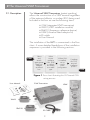
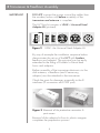
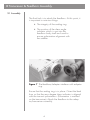
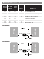
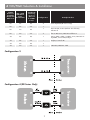
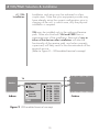
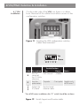
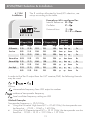
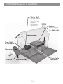
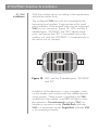
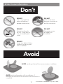
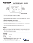
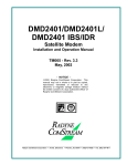
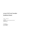
Andrew Corporation Earth Station Electronics
Universal VSAT Transceiver (UVT)
User and Installation Guide
August 2007 Version 2.0
Table of Contents
2
2
2
2
1. Introduction
1.1. Scope
1.2. Warnings
1.3 Disclaimers
3
3
2. The Universal VSAT Transceiver 2.1. Description
4
5
3. Transceiver & Feedhorn Assembly
3.1. Assembly
7
10
16
4. VIM/FReD Selection & Installation
4.1. VIM installation
4.2. Installing FReD
17
5. Operation & Maintenance
17
6. Site Owner Information
Proprietary Notice:
The technical data contained herein is proprietary to
Andrew Corporation. It is intended for use in installation and
maintenance of Andrew supplied equipment.
This data shall not be disclosed or duplicated in whole or in
part without the express written consent of
Andrew Corporation.
1
1 Introduction
1.1. Scope
This document is intended to provide information of a
general nature to the supplier, installer and end user of
the Andrew Universal VSAT (Integrated) Transceiver.
It is highly recommended that this document is fully
read and understood before installation and use of the
transceiver. The Andrew transceiver is a professional
product, which should only be specified and installed
by professionals. It should not be relocated from its
installed position except under the supervision of a
professional. Observing these instructions will ensure
that the Andrew transceiver offer many years of
reliable service.
1.2. Warnings
This Andrew Corporation transceiver is a professional
product. It contains an RF transmitter. It is therefore a
source of nonionizing radio frequency radiation.
Qualified professionals with professional equipment
are required to install and configure this unit. In case
of emergency, disconnect the source of power for the
transceiver. Usually this means disconnection of the
indoor unit (or modem) from the power outlet.
In addition to the risk of damage or degradation to the
equipment, failure to observe any or all of the
following instructions may result in bodily harm, serious
injury or even death.
For further safety information, see the chapter entitled
Site Owner Information.
1.3 Disclaimers
ANDREW Corporation disclaims any liability or
responsibility for damage caused as the results of
misprints in this manual.
ANDREW Corporation disclaims any liability or responsibility for the results of improper or unsafe installation and maintenance practices.
ANDREW Corporation disclaims any liability or
responsibility for violation of any legal ETSI, FCC or
regulatory system homologation requirements caused
by the use of the UVT system components.
2
2 The Universal VSAT Transceiver
2.1. Description
The Universal VSAT Transceiver (patent pending)
allows the construction of a VSAT terminal regardless
of the antenna/reflector or modem (IDU) being used.
Included in the box set are the following items:
• -F16X (integrated VSAT transceiver)
• VIM10 (VSAT installation module)
• FReD10 (Frequency reference device)
• UFAK (Universal feed adaptor kit)
• IFL cable
• User Manual
The installation of the UVT is summarized in the flow
chart. A more detailed breakdown of the installation
sequence is provided in the following sections.
Select
and
attach
appropriate
feed horn
adaptor
and feed
horn
START
Select
correct
interface
(VIM, FReD
or neither)
according
to modem
type
Where VIM
is installed,
set up
correct
switch
configuration
Complete
the VSAT
terminal
installation
process
END
Figure 1 Flow chart illustrating the UVT based ODU
User Manual
set-up process
-F16X Transceiver
VIM10
FReD10
IFL Cable
3
UFAK
3 Transceiver & Feedhorn Assembly
IMPORTANT
DO NOT connect the power source (the cables from
the modem/indoor unit) before assembly of the
transceiver and antenna is complete.
The UVT box kit contains a UFAK – Universal Feed
Adaptor Kit (pictured).
Figure 2
UFAK - the Universal Feed Adaptor Kit
By way of example the installation sequence below
demonstrates the set up of the UVT with Andrew
feedhorn and adaptor. The principal can be easily
extended to the fitting of Prodelin or Patriot feed
horns and adaptors.
Before assembly of the transceiver electronics to the
dish antenna, a feedhorn (and if necessary,
adaptor) must be attached to the transceiver.
Check the parts for damage, especially to the 3
interfaces (2 connectors and OMT port).
Figure 3 Removal of the protective connector &
port covers
Removal of the adaptor kit from its plastic wrapper
completes the preparation process.
4
3 Transceiver & Feedhorn Assembly
UVT Type
TX Power RX polarization
X-Polar to TX
RX Polarization
Co-Polar to TX
XR3 Series
2, 3 and 4 Watt Versions
Yes
No
DR5 Series
3, 4 and 5 Watt Versions
Yes
Yes
DR7 Series
6, 7 and 8 Watt Versions
Yes
Yes
3.1 Assembly
The adaptor/transceiver interface may now be
assembled.
Figure 5 Transceiver & adaptor, showing correctly located adaptor ring
With the adaptor sealing ring secured in the correct
position, use the four screws supplied to connect the
adaptor to the transceiver as shown in Figure 6.
Figure 6 Connecting the adaptor to the transceiver
Care should be taken not to overtighten hardware.
5
3 Transceiver & Feedhorn Assembly
3.1 Assembly
The final task is to attach the feedhorn. At this point, it
is important to note two things
• The integrity of the sealing ring
• The position of the skew angle
indicator which is cast into the
feedhorn body itself and used to
ensure polarization alignment with
the satellite
Figure 7 The feedhorn/adaptor interface with adaptor ring
Ensure that the sealing ring is in place. Orient the feed
horn so that the zero degree skew indicator is aligned
with the transmit polarization. (Polarization is marked
on the transceiver). Attach the feedhorn to the adaptor/transceiver assembly.
6
3 Transceiver & Feedhorn Assembly
3.1 Assembly
Figure 8 Connecting the feedhorn to the adaptor
Care should be taken not to overtighten hardware.
Depending on the particular modem and VSAT
network set-up requirements, assembly of the
transceiver and feed is now complete and is ready for
integration with the antenna.
4 VIM/FReD Selection & Installation
Included with the UVT are two system configuration
devices. Deciding which to install depends on the
modem being used.
Some common L-band modems and manufacturers are
listed in the following table. Use the table to
identify which configuration should be used, then refer
to the installation sections for more detailed information
on how to set-up and connect the device.
In the event that the specific modem is not listed, use VIM as the default installation device.
7
4 VIM/FReD Selection & Installation
10 MHz
Reference
Available
On Modem
RX If Port?
950 - 2150
MHz RX IF
Input
Bandwidth?
No
No
No
4
No
No
Yes
1
No
Yes
No
No
Yes
Yes
Yes
SatLabs IFL
Switching
Protocol
(DC Level
& 22 KHz
Tone)?
Configuration
Example Modem
Gilat SkyEDGE (XR Series Only)
1
HNS HX-150; ViaSat (Linkstar & Surfbeam);
Advantech
2
Shiron iRG-Series; NDSatCom hlPerion
1
iDirect 3000-, 5000-, & 7000- Series; NDSatCom
SkyWAN; Comtech EF; Radyne
Radyne; Comtech EF
No
No
Yes
No
Yes
1
Yes
Yes
No
1
Yes
Yes
Yes
3
STM-1910; HNS HX - 200
Configuration 1
Configuration 2
8
4 VIM/FReD Selection & Installation
10 MHz
Reference
Available
On Modem
RX If Port?
950 - 2150
MHz RX IF
Input
Bandwidth?
No
No
No
4
No
No
Yes
1
No
Yes
No
No
Yes
Yes
Yes
SatLabs IFL
Switching
Protocol
(DC Level
& 22 KHz
Tone)?
Configuration
Example Modem
Gilat SkyEDGE (XR Series Only)
1
HNS HX-150; ViaSat (Linkstar & Surfbeam);
Advantech
2
Shiron iRG-Series; NDSatCom hlPerion
1
iDirect 3000-, 5000-, & 7000- Series; NDSatCom
SkyWAN; Comtech EF; Radyne
Radyne; Comtech EF
No
No
Yes
No
Yes
1
Yes
Yes
No
1
Yes
Yes
Yes
3
STM-1910; HNS HX - 200
Configuration 3
Configuration 4 (XR Series Only)
9
4 VIM/FReD Selection & Installation
4.1 VIM
Installation
Installation and set-up may be achieved in a few
simple steps. Note that your equipment provider may
have already set-up the correct configuration prior to
shipping of the unit, in which case, only the physical
installation is required.
VIM may be installed only in the outbound/receive
path. Note also that both VIM and FRED form a
permanent part of the installation. Removal of any or
either of the devices after installation will alter the
functionality of the receive path, and unless properly
supervised, will likely result in the discontinuance of the
terminal service.
(Refer to Figure 9 – VIM-enabled terminal concept)
TX
TX
Modem
RX
Indoor
1
Polarization
Co
Cross
Reference
Internal
External
VIM
Band
10.70 - 11.70
10.95 - 11.45
10.95 - 11.70
11.20 - 11.70
11.70 - 12.75
11.70 - 12.20
11.70 - 12.45
12.25 - 12.75
Figure 9 VIM-enabled terminal concept
10
Transceiver
2
RX
Outdoor
4 VIM/FReD Selection & Installation
4.1 VIM
Installation
The first step in the VIM installation process is to
identify the correct switch positions for the application.
START
Select the
10 MHz Rx
reference
source
Select
band by
configuring
3 switches
(1,2 and 3).
Select the
required
band/LO
Select the
required
polarization
(Co or X)
END
Only
applies
when used
with
DR series
Universal
Transceivers.
XR series
are X polar
only.
If the modem
has a
reference
available on
the RX port,
it is
recommended
that this is
used. Consult
your modem
specification
See the
look-up table
to cross
reference the
switch
position
versus
required LO.
Some
bands are
“spectrally
inverted”.
Consult your
modem
user guide
to see how
the modem
should be
configured.
Figure 10 Flow chart describing the VIM switch set-up
IMPORTANT!
Polarization setting for XR3 series must always be
X-polar.
VIM supply voltage for DR5 series must always be
>18.5 V
On cable runs of more than 30 meters, premium
coax cable must be used with a solid copper center
conductor.
11
4 VIM/FReD Selection & Installation
4.1 VIM
Installation
On the under side of the VIM unit, there is a rubber
boot. Removal of this rubber boot allows access to the
configuration switches.
Figure 11 Locating the VIM configuration switches, rubber boot removed
Up
Down
R P 1 2 3
Label Description
R
P
1
2
3
Switch Position
Up Down Sets the
VIM internal source of
the 10 MHz
reference
Notes
Modem
Sets the
Co-polar Cross-polar Applies only polarization
to DR-series*
Selects the
LO/band
See the band
selection table
* For all XR-series installations the “P” switch should be set down
Figure 12 Switch layout and function table
12
4 VIM/FReD Selection & Installation
4.1 VIM
Installation
The 3 switches allocated to band/LO selection, are
set-up according to the table.
Example on left is configured for:
Internal Reference: R is Up
Up
Down
Co-Polar:
P is Up
Universal Low:
1 is Up
2 & 3 are Down
R P 1 2 3
Name
RF Input/GHz LO/GHz IF Output/MHz
Switch#
/Position
Low
High
Low
High 1
US Domestic
11.70
12.20
13.15
950
1450
down down up
Euro-Low
10.95
11.45
12.40
950
1450
-
11.70
12.45
13.40
950
1700
Universal Low 10.70
11.70
9.75
950
1950
Universal High 11.70
12.75
10.60
1100
2150
-
11.20
11.70
12.65
950
Euro -High
12.25
12.75
13.70
950
-
10.95
11.70
950
12.65
2
Spectrum
Inversion1
3
Yes
down up
down Yes
down up
up
Yes
up
down down No
up
down up
No
1450
up
up
down Yes
1450
up
up
up
Yes
1700
up
up
down Yes
In order to find the IF output from the UVT receiver/LNB, the following formula
may be used.
Where;
intermediate frequency from VIM output to modem
outbound transponder frequency
local oscillator frequency setting on VIM
Worked Examples
Transponder frequency is 12.03 GHz.
• Using the Universal High band (LO = 10.60 GHz), the transponder can be found at… 12.03 – 10.60 = 1.43 GHz
• Using the US Domestic band (LO = 13.15 GHz), the transponder can be found at… 12.03 – 13.15 = -1.12 GHz = 1.12 GHz
13
4 VIM/FReD Selection & Installation
VIM or FReD
u Located indoors
u Must be less u
than .3 m from
Modem
Must not be
covered or obstructed
Modem
u Located indoors
u Less than .3 m from VIM or FReD
INDOORS
Coax Cable
to Transceiver
Transceiver
Antenna
Coax Cable
to Modem
OUTDOORS
14
4 VIM/FReD Selection & Installation
4.1 ViM
Installation
With the switches set-up according to the requirements,
replace the rubber boot.
The configured VIM may now be connected to the
transceiver (and modem, if appropriate at this point),
and installation of the terminal may now be continued.
VIM has two connectors (Figure 13 - VIM, and the 2
labelled ports, “MODEM” and “RX”). Identify these
ports, and ensure that “RX” is connected only to the
outdoor unit, and that “MODEM” is connected only to
the indoor unit (or modem).
Figure 13 VIM, and the 2 labelled ports, “MODEM” and “RX”
Installation of the electronics is now complete, switch
on the modem and continue with the satellite terminal
set-up process. When power is applied to the VIM
module from the modem, a red LED will light to show
the operation. On continuously indicates VIM is in
frequency conversion mode. Double flash indicates
VIM is in transparent mode. Single flash indicates VIM
is not operating correctly
15
4 VIM/FReD Selection & Installation
4.2 FReD
Installation
Fitting the FReD ancillary is extremely simple. There are
no configuration switches. The FReD device is fitted in
the outbound/receive path, between the ODU/transceiver and the IDU/modem.
Identify from the FReD module which is the “MODEM”
(modem/IDU) port, and which is the “RX” (RX, ODU)
port. (See Figure 14 - Illustration of FReD, with two
labelled ports for an explanation.)
Connect the FReD unit in line, between the modem RX
port and the transceiver RX port.
Figure 14 Illustration of FReD, with two labelled ports
Installation of the electronics is now complete. Switch
on the modem and continue with the satellite terminal
set-up process. When power is applied to the FReD
module, a blue LED will light to show the operation.
16
5 Operation & Maintenance
The UVT transceiver operation is controlled by the
modem. No operational intervention is necessary after
installation is complete.
If the network or system becomes unusable, it is
unlikely that the transceiver is the source of the
problem. Consult your network operator or service
provider, or modem/indoor unit operating guide for
instructions.
The UVT transceiver is maintenance free. In the unlikely
event of failure, the transceiver shall be professionally
removed, replaced and disposed of. There are no user
serviceable parts or components inside. Do not open
the transceiver.
6 Site Owner Information
Ensure that the site owner information sheet is handed
over to those responsible for the installation site. It is
important for the health and safety of the owner, and
for the continued high performance of the system, that
the information sheet is read and understood.
The site owner safety sheet is depicted on the
following pages.
17
6 Site Owner Information
Do
Take precautions to keep children and pets away from the
installation site.
Inspect from a safe distance, the installation after instances of severe weather (strong winds
or extreme temperatures) or impact. If damage is suspected, disconnect the indoor unit or
modem from the power outlet and seek professional advice.
Don’t
DO NOT
Look into the
feedhorn or
waveguide.
DO NOT
Modify the
approved feed
horn and adaptor
set-up.
DO NOT
Operate the device
when not securely
attached to the
intended antenna
installation.
DO NOT
Operate the device
without a feedhorn.
18
6 Site Owner Information
Don’t
DO NOT
Use a non-matched
antenna/feedhorn/
adaptor combination.
DO NOT
Obstruct the area
between the antenna
and the transceiver.
DO NOT
Attempt to dismantle
the unit – there are no
user serviceable parts
inside.
DO NOT
Attempt to service
or modify the
installation.
DO NOT
Attach any objects (heavy
or otherwise) to any part
of the installation.
Avoid
AVOID standing in front of the communications installation.
AVOID continued operation of the installation, if
damage to the antenna or transceiver has occurred or is
suspected.
19
II-102147-EN © ANDREW Corporation 2007