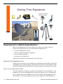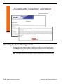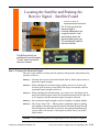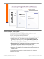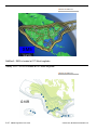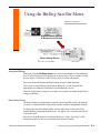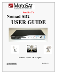
1
Mo b i l eInternet Sa t e l l i t e . C O M Satellite Mobility Support Network (SMSN) HughesNet User Guide June 27, 2010 © 2004-2010, MobileInternetSatellite.com Satellite Mobility Support Network (SMSN) HughesNet® User Guide Version 2.2 by MobileInternetSatellite.com Yuma, Arizona Copyrig ht Notices Licensee agrees that on all copies of the M aterials it shall affix the following notice: © Copyright BJ Consulting, Inc. 2004-2010 and M obileInternetSatellite.com 2004-2010. All Rights Reserved. Unauthorized use or distribution is strictly prohibited. W ARRANTY DISC LAIMER; EXC LUSION OF CERTAIN DAM AGES The Materials delivered hereunder are provided "AS IS", without any warranty of any kind. ALL W ARRANTIES, EXPRESS, IMPLIED OR ST ATUTORY, INCL UDING W ITHOUT LIMITATION, THE IM PL IED W AR RANTIES OF MERCH ANTABILITY, FIT NESS FOR A PARTICUL AR PURPOSE AND NON-INF RIN GEM ENT , ARE HEREBY DISCLAIMED. INDEPENDENTL Y OF ANY OTH ER LIMITATION HEREOF AN D REGAR DLESS OF WH ETH ER TH E PU RPOSE OF ANY REMEDY SET FOR TH HEREIN IS SERVED, IT IS AGREED T HAT IN NO EVENT SHALL LICENSOR (OR IT S LICENSOR S, AS APPLICABLE) BE LIABLE FOR SPECIAL, INCIDENTAL OR CONSEQUENTIAL D AM AGES OF ANY K IN D RELATING TO T HE M AT ER IAL S OR THIS AGREEMENT, WHETHER LIABILITY IS B ASED ON BREACH OF A CONTRACT UAL, ST ATUTORY OR COM MON LAW DUTY OF ANY KIN D. M o b i l e I n te rn e tS a tel l i t e . c o m U s e r G u i d e Table of Contents Satellite Mobility Support Network (SMSN) User Guide for HughesNet Chapter 1: Introduction to the SMSN HughesNet User Guide Introduction 1-2 Overview of the SMSN HughesNet Mobile User Guide 1-3 HughesNet Environment 1-4 Pointing the Antenna 1-5 Requirements for a Mobile HughesNet User Setting Up Your HughesNet Account Home, Pro, and ProPlus Service Plans Small Office and Business Internet Service Plans PowerPak Getting Your Satellite and Mobility Equipment Satellite Equipment Mobility Kit Receiving Hands-on Training Using DSSatTool, from Don Bradner and DatastormUsers.com 1-6 1-6 1-6 1-7 1-7 1-7 1-7 1-7 1-7 1-7 HughesNet System Components The Outdoor Unit (ODU) The Dish or Reflector The Feed Arm LNB Transmitter Ku-band The Indoor Unit (IDU) – HughesNet Satellite Modem The HughesNet Satellite Modem Lights The Interfacility (IFL) Dual Coaxial Cables 1-8 1-9 1-9 1-9 1-10 1-10 1-10 1-11 1-11 1-13 The SMSN Mobility Kit Mobility Kit Components 1-14 1-14 Co-pol, Cross-pol, and Antenna Pointing Pointing the Antenna Properly Defining Inroute and Outroute Communications Defining Polarization Pointing the Antenna and Fine-tuning 1-16 1-16 1-18 1-18 1-19 HughesNet Customer Contacts HughesNet Support Options 1-20 1-20 © 2004-2010, MobileInternetSatellite.com Table of Contents iii Miscellaneous Information HughesNet Satellites Networking and HughesNet Support Online User Groups Information about RF energy Will the HughesNet Antenna Harm Me? Can You Be More Specific? What Does This Mean to Me? HughesNet Fair Access Policy (FAP) The HughesNet Policy How Does it Work? Download Bucket Sizes Refill Rates Upload Bucket Sizes 1-21 1-21 1-21 1-21 1-21 1-22 1-22 1-22 1-22 1-22 1-23 1-23 1-23 1-24 Summary 1-25 Chapter 2: Every Time You Move - Redeploying Your HughesNet VSAT iv Table of Contents Introduction 2-2 Commissioning and Installation 2-3 Verifying the Location & Selecting the Satellite 2-4 Entering the Satellite Parameters Manually 2-5 Verifying the Satellite & Transmit Radio Parameters 2-6 Getting the Numbers for Setup & Peaking the Receive Signal 2-7 Passing Cross-pol & Connecting to the Registration Server 2-8 Registering the VSAT 2-9 Accepting the Subscriber Agreement 2-10 Entering the SAN & PIN and the Welcome Message 2-11 Displaying Your Modem’s Site ID and IP Address 2-12 Selecting a Suitable Camp Site Getting the Elevation, Azimuth, and Polarization/Skew 2-13 2-13 Using DSSatTool Using DSSatTool (continued) 2-14 2-15 Setting up the Tripod and Offset Adapter Setting up the Tripod and Offset Adapter – The Wrong Way! 2-16 2-17 Plumbing the Mast, Assembling, & Adjusting the Antenna Step 1: Getting Ready & Plumbing the Mast — The Built-in Bubble T-Level 2-18 2-18 © 2004-2010, MobileInternetSatellite.com Step 1: Getting Ready and Plumbing the Mast — The Alternate Mast Level Attaching and Calibrating a Bubble T-Level Step 2: Installing the Reflector and Mount Step 3: Adjusting the Elevation Step 4: Adjusting the Skew/Polarization Setting Step 5: Installing the Rx-Tx Feed Arm Step 6: Re-checking the Plumb Step 7:Adding the Ballast Preparing for Inclement Weather What If I Don’t Add Enough Ballast? 2-19 2-19 2-20 2-21 2-22 2-23 2-24 2-25 2-26 2-26 Locating the Satellite and Peaking the Receive Signal Step 1: Attaching the Cables and the Meter Antenna Pointing Software (OPI Only) Checking the Signal Strength & Peaking the Signal (OPI Only) Passing an Automatic Cross-pol Test Using PC-OPI Step 2: Locating the Correct Satellite Step 3: Peaking the Received Signal MobileInternetSatellite.com Setup Card Setup Summary with an OPI, PC-OPI, or Soft-OPI: Setup Summary with a BirDog 2-27 2-27 2-28 2-29 2-30 2-31 2-32 2-33 2-34 2-35 2-35 Transporting Your System 2-36 Summary 2-37 Chapter 3: Help and Troubleshooting Information Introduction 3-2 The HughesNet.com Web Sites Customer Care Web Site 3-3 3-4 The HughesNet User Guides 3-5 The Raven & Prodelin Installation Guides 3-6 Miscellaneous Modem Operations The Advanced Page HN7000S Force Ranging Page Uploading a Config File Speed Tests Using Two Satellite Meters 3-7 3-8 3-9 3-10 3-11 3-12 Online User Group Information MobileInternetSatellite.com - RVNetworking.com RV2WaySat Yahoo Group 3-13 3-13 3-14 © 2004-2010, MobileInternetSatellite.com Table of Contents v DatastormUsers.com Web Site 3-14 Networking Information How to Connect to Your Linksys Wireless Router How to Change the SSID and Channel on the WRT54GL: How to Change the Administrator Password on the WRT54GL: How to Enable and Configure WEP How to Save the Configuration on the WRT54GL How to Reset the WRT54GL How to Restore the Configuration on the WRT54GL How to View Network Status Information on the WRT54GL More Information 3-15 3-16 3-16 3-16 3-16 3-17 3-17 3-17 3-18 3-18 Summary 3-19 Appendix A: Longitude, Latitude, & Coverage Maps Longitude and Latitude Map SES-Americom 6 – AMC6 is located at 72 West longitude. SES-Americom 9 – AMC9 is located at 83 West longitude. SES-Americom 3 – AMC3 is located at 87 West longitude. Intelsat Americas 8 – IA8 is located at 89 West longitude. Galaxy 11 – G11 is located at 91 West longitude. Intelsat Americas 6 – IA6 is located at 93 West longitude. Galaxy 3C – G3C is located at 95 West longitude. Galaxy 25 – G25 is located at 97 West longitude. Galaxy 16 – G16 is located at 99 West longitude. G16 replaced G4R in 2006. SES-Americom 4 – AMC4 is located at 101 West longitude. SatMex6 – SM6 is located at 113 West longitude. SatMex5 – SM5 is located at 117 West longitude. Galaxy 10 R – G10R is located at 123 West longitude. Horizon 1 – HR1 is located at 127 West longitude. Galaxy 27 - G27 is located at 129 West longitude. A-2 A-4 A-5 A-5 A-6 A-6 A-7 A-7 A-8 A-8 A-9 A-9 A-10 A-10 A-11 A-11 Appendix B: Assembling the Offset Adapter Assembling the Tripod & Offset Adapter — With the Stanley Keeper Assembling the Tripod & Offset Adapter (continued) Positioning the Adapter Hardware Assembly — With the Stanley Keeper Positioning the Adapter Hardware Assembly — With the Stanley Keeper B-2 B-3 B-4 B-5 Assembling the Offset Adapter — Without the Stanley Keeper Positioning the Adapter Hardware Assembly — Without the Stanley Keeper B-6 B-7 Appendix C: Tips for Safe & Stable Tripod Setups Introduction Using Ballast vi Table of Contents C-2 C-2 © 2004-2010, MobileInternetSatellite.com Using Anchors vs. Ballast, with a Narrower Stance Using a Very Wide Stance Setting the Feet vs. Tying Them Together Additional Safety Suggestion C-3 C-3 C-4 C-4 Appendix D: Programming & Using the BirDog Satellite Meter Using & Programming the BirDog Using the BirDog Basic Startup Screen Changing the BirDog Configuration Finding the Satellite D-2 D-3 D-3 D-4 D-5 Programming the BirDog Computers without 9-pin Serial Port and BirDogs with the Serial Connection Installing the Drivers for BirDogs D-6 D-7 D-7 Appendix E: Using a Macintosh with HughesNet Mobile Satellite Internet and the Macintosh Satellite Finder for the Macintosh - Determining Azimuth, Elevation & Skew Customizing Satellite Finder Getting Your Pointing Parameters Translating the Calculated Skew Value - An Example SatTool for Macs - Setting Longitude & Latitude in Modem’s Firmware SoftOPI - Displaying Signal Strength During Setup E-2 E-2 E-3 E-3 E-3 E-4 E-4 Steps for Setting Up E-5 Miscellaneous Macintosh Networking Functions Checking the Active LAN Connection Using Your Macintosh Powerbook as an Access Point Putting the Apple Airport Icon in the Menu Extras Turning off the Apple Airport Setting Up a Macintosh to Use Dynamic IP Addressing Setting Up a Macintosh to Use Static IP Addressing E-7 E-7 E-8 E-8 E-8 E-9 E-9 © 2004-2010, MobileInternetSatellite.com Table of Contents vii viii Table of Contents © 2004-2010, MobileInternetSatellite.com BCJ H C A oP nT sE uRl 1 Introduction to the SMSN HughesNet User Guide SMSN is the Satellite Mobility Support Network. © 2004-2010, MobileInternetSatellite.com Introduction to the SMSN HughesNet User Guide 1-1 Chapter 1 – Overview MobileInternetSatellite. com The following topics will be discussed: Overview of the SMSN User Guide Requirements for a Mobile User Set Up Your HughesNet Account Get Your Satellite & Mobility Equipment Receive Hands-on Training Use DSSatTool HughesNet System Components Mobility Kit Components Co-pol, Cross-pol, & Antenna Pointing HughesNet Customer Contacts Miscellaneous Information Introduction The Satellite Mobility Support Network (SMSN) HughesNet® User Guide will describe how to be a successful mobile HughesNet user. It is meant to be a single source of information for members, to successfully move and redeploy Very Small Aperture Terminals (VSATs). This introductory chapter will provide an overview of the entire manual. The HughesNet environment will be described, along with the different components of a mobile system. Contact information for HughesNet will be provided and their policy for fair access of the shared bandwidth is also discussed. Several miscellaneous topics are covered. I would like to thank my husband, Joe, for his assistance and support, and all of the members of the RV2WaySat Yahoo group, especially Terry Cannon, Dave Heibeck, Stan Miller, Glenn Simpson, Don Bradner, and Ron Ruward, for all of the expert advice and suggestions. Thanx for helping to make this User Guide a great resource for RVers traveling with two-way satellite dishes! Note This user guide is available from MobileInternetSatellite.com and other Satellite Mobility Support Network (SMSN) dealers. This alliance of two-way satellite dealers is dedicated to providing RVers with satellite Internet and supporting them, so they stay online. 1-2 SMSN HughesNet User Guide © 2004-2010, MobileInternetSatellite.com Overview of the SMSN HughesNet Mobile User Guide The following major topics will be covered in this manual: • Chapter 1 - Introduction and Overview — Overview of this manual — HughesNet environment — Requirements for mobile users — HughesNet system components — Mobility kit components — Co-pol, cross-pol, and antenna pointing — HughesNet customer contacts — Miscellaneous information • Chapter 2 - Every Time You Move: Redeploying Your VSAT - Although the focus of this chapter is setting up every time you change location, the chapter begins with a look at the commissioning process. — Installation and commissioning — Selecting a suitable camp site — Using DSSatTool to update the location — Setting up the tripod and offset adapter — Plumbing the mast and adjusting the antenna settings — Adding ballast and rechecking plumb — Locating the satellite, peaking the receive signal, and passing cross-pol — Transporting the satellite equipment • Chapter 3 - Help and Troubleshooting Information — The HughesNet.com web sites — The HughesNet user guides — The Raven installation guide — Miscellaneous modem operations — User groups — Networking information • Appendices — Satellite coverage maps — How to assemble the hardware set — Tripod Setup Tips — How to program the BirDog — HughesNet for Macintosh information © 2004-2010, MobileInternetSatellite.com Introduction to the SMSN HughesNet User Guide 1-3 HughesNet Two-way Satellite System Operation MobileInternetSatellite. com Hugh esNet HughesNet Environment The graphic shows how the remote terminal or VSAT fits into the HughesNet system architecture. Let’s start by clearly defining what is meant by VSAT: VSAT — Per Webopedia.com (http://www.webopedia.com/): VSAT is Short for Very Small Aperture Terminal. A VSAT is an earthbound station used in satellite communications for data, voice and video signals, excluding broadcast television. A VSAT consists of two major parts, as follows: Definition • A transceiver - This is placed outdoors in direct line of sight to the satellite. It is part of the Feed Arm attached to the dish. • A device that is placed indoors, to interface the transceiver with the end user's device. This is your HughesNet satellite modem. The transceiver receives and sends signals, to a satellite transponder in the sky. The satellite transponder receives and sends signals, to a ground station computer located at the HughesNet NOC (Network Operations Center). Each end user is interconnected with another computer at the NOC, via the satellite, forming a star topology. It is also called the Hub and Spokes topology. The computer at the NOC (the Hub) controls the entire operation, for its portion of the network. For one end user to communicate with another, the transmission has to first go to the Hub, which then retransmits it (via the satellite) to the other end user's VSAT. 1-4 SMSN HughesNet User Guide © 2004-2010, MobileInternetSatellite.com Pointing the HughesNet Satellite Dish MobileInternetSatellite.com Azimuth Polarization Elevation Pointing the Antenna The antenna uses a three axis pointing system, which you will adjust, after you move: • Azimuth - This is the magnetic compass direction (angle of sighting) at which you point the dish. It is a side-to-side adjustment. • Elevation. - This is the angle above the horizon, at which you point the dish. This is an up-and-down adjustment. • Polarization - The polarization or skew is set after each move. This is a rotational adjustment These adjustments are illustrated above. The corresponding mechanical adjustments on the antenna are explained in the next chapter. © 2004-2010, MobileInternetSatellite.com Introduction to the SMSN HughesNet User Guide 1-5 Getting Your Equipment MobileInternetSatellite. com Requirements for a Mobile HughesNet User Being a mobileHughesNet user means that you can “take your Internet with you!” Here are the requirements to be a successful mobile HughesNet user: • • • • Set up your HughesNet account. Get your satellite and mobility equipment. Receive hands-on training. Learn how to use DSSatTool. Each of these requirements is discussed in more detail later. Setting Up Your HughesNet Account Setting up your account involves providing some information to the installer or dealer and selecting the service plan and options. The dealer will get a Site Account Number (SAN) and Personal Identification Number (PIN), which are needed to commission your modem. Home, Pro, and ProPlus Service Plans The most commonly selected service plans use the standard .74 meter dish and a 1-watt transmitter. The lowest cost HughesNet service plan is the Home Service, which provides up to 700 Kbps down and 128 Kbps up for $59.99 per month. Another popular choice is the Pro plan. For $69.99 per month, it provides up to 1 Mbps down and 200 Kbps up. 1-6 SMSN HughesNet User Guide © 2004-2010, MobileInternetSatellite.com Then there is the ProPlus plan, which provides up to 1.5 Mbps down and 200 Kbps up, for $79.99 per month. You can also get a static IP address with the ProPlus plan, for another $10 per month. With all three plans you receive 5 email accounts. There is no service contract with used equipment. Extended service warranties, for on-site service, and dial-up access may be available. Small Office and Business Internet Service Plans Equipment costs are higher, but you receive the larger .98 meter dish and a 2-watt transmitter. The service plans cost $99.99 and $179.99 per month, for 1.5 Mbps and 2.0 Mbps down, 300 Kbps and 500 Kbps up, respectively. With this equipment you can extend coverage to much or all of Canada and/or Mexico, depending on satellite. PowerPak HughesNet now offers the 98 meter dish and a 2-watt transmitter as an add-on option to any service plan. For $299.99, it extends the coverage area and reduces rain fade. Getting Your Satellite and Mobility Equipment After you have provided the necessary information to set up your HughesNet account, your equipment will be ordered. You will need the HughesNet satellite equipment and mobility accessories to take your system on the road. Satellite Equipment The satellite equipment is provided by Hughes Network Systems. This includes the DW7000 and HN7000S satellite modem, a .74 or .98 meter dish, and the feed arm, which holds the LNB and a 1- or 2-watt transmitter. Shown on the previous page is the latest HughesNet outdoor equipment, the metal Prodelin dish and feed arm. Mobility Kit The mobility kit includes all of the accessories you will need to move your satellite system to a new location and get back online. Items include at the least: a tripod and offset adapter, an elevation adjuster, a meter, a compass, a level, a method of attaching ballast, and cables. Some of these things are pictured on the previous page. Receiving Hands-on Training The original installation and commissioning is performed by a professional installer. It is also the responsibility of the original installer or dealer, to train the new mobile user in proper alignment and verification procedures, when moving the satellite dish. Receiving hands-on training is very important - it can make the difference between a stressful experience and enjoying your new system immediately. Using DSSatTool, from Don Bradner and DatastormUsers.com For the commissioning of your modem, the installer/trainer must use the web interface of your modem and the Registration - Installer functions. After commissioning, Don Bradner’s DSSatTool provides an easier way to get your modem to communicate with the satellite from a new location. It is also uses fewer network resources. This is discussed in Chapter 2, Every Time You Move - Redeploying Your HughesNet VSAT. © 2004-2010, MobileInternetSatellite.com Introduction to the SMSN HughesNet User Guide 1-7 Components of a HughesNet VSAT System LNB MobileInternetSatellite. com Transmitter Antenna RG-6 Dual Coaxial Cables (50-75’) Short TX and RX Coaxial Cables Sat-In Sat-Out Rx-Tx Feed Arm Wall plate or F/adapter HughesNet Satellite Modem (IDU) HughesNet System Components The figure above illustrates the four major components of a HughesNet VSAT system: • The Outdoor Unit (ODU) - This comprises the antenna and the feed arm, which has the receiver and transmitter. • The Indoor Unit (IDU) - This is the HughesNet Model DW6000, DW7000, or HN7000S satellite modem. • The Interfacility Link (IFL) Cables - The cables connect the IDU to the ODU. • The Software - This is contained in the firmware of the satellite modem. The first three of these four components will be discussed in more detail, later in this chapter. The software is discussed in Chapter 2, Every Time You Move Redeploying Your HughesNet VSAT. 1-8 SMSN HughesNet User Guide © 2004-2010, MobileInternetSatellite.com The Outdoor Unit (ODU) TV LNB MobileInternetSatellite. com The HughesNet Raven ODU The Direcway Gen5 ODU Raven Feed Arm The Outdoor Unit (ODU) The ODU or antenna includes the dish, or reflector, and the feed arm, which holds the active elements (transmitter and receiver). These are pictured above. The Dish or Reflector The older dish, shown on the left with the TV attachment, is made of fiberglass, with an embedded wire mesh. It measures 0.74 meter in surface area (39” x 23”). The newer Raven dish is still .74 meter, but is rounder (34 1/4" x 28 1/2") and it is made of a lightweight metal. Often, when only referring to the dish, without the feed arm, the term reflector is used. The latest Prodelin dish was shown earlier. The Feed Arm Located on the fully assembled VSAT dish assembly, the Rx-Tx feed arm is normally removed and safely stored, as part of the process for moving to a new location. The feed arm consists of the feed support arm and the outdoor electronics. All of the active outdoor components connect to the support arm, which also adds strength (and weight) to the completely assembled antenna. The outdoor electronics consist of the LNB, which receives outroute (from the NOC) Ku-band signals from © 2004-2010, MobileInternetSatellite.com Introduction to the SMSN HughesNet User Guide 1-9 the satellite, and the transmitter, which transmits inbound (to the NOC) Ku-band signals to the satellite. Power is supplied by the HughesNet satellite modem. For those who are interested, this is discussed in more detail, below. LNB The Low-Noise Block down-converter (LNB) is used to amplify and frequency convert outroute signals received by the antenna, for input into the modem via the Sat-In cable. The antenna receives the outbound signal in the Ku-band frequency, for input to the wave guide end of the LNB. The LNB first amplifies the input Ku-band signals. It then uses a local oscillator (LO), to frequency translate input signals to L-band frequencies, which are used on the coaxial cables. The signal noise value is an electrical specification for the LNB, which is critical to outroute signal (your received signal) quality performance. The lower the noise figure, the better the signal quality performance will be. The LNB is powered from the modem, via a DC power supply coupled on the coaxial RF input connector, which connects to the receive IFL cable. Transmitter The transmitter is used to frequency translate and power amplify inroute signals from the modem and output them to the antenna, for transmission to the satellite. The modem sends the inroute signal at an L-band frequency to the transmitter, using Sat-Out and the transmit coaxial cable. This signal is input to the transmitter, where it is frequency converted to the transmit Ku-band frequency, using a nominally fixed local oscillator (LO). This Ku-band signal is then power amplified to operate the transmitter at a nominal one-watt output power (at saturation). The fixed output power is input to the antenna, for transmission to the satellite. The transmitter is powered from the modem, via a DC power supply coupled on the coaxial RF output connector, which connects to the transmit IFL cable Ku-band Communications satellites send and receive electromagnetic Ku-band signals, which are in the super high-frequency range. Microwave phone signals, which are relayed between tall towers, are in this same frequency range. However, satellite Ku-band signals are usually not susceptible to interference from these towers. 1-10 SMSN HughesNet User Guide © 2004-2010, MobileInternetSatellite.com The Indoor Unit (IDU) MobileInternetSatellite. com LAN 2 Transmit 4 Rece ive 3 Syste m 5 Receive Power 1 Transmit LAN Power HN7000S (back) HN7000 S (front) 1 The Indoor Unit (IDU) – HughesNet Satellite Modem The HughesNet Model DW6000, DW7000, or HN7000S modem supplies DC power to the LNB and the transmitter. It also transmits the inroute signal and receives the outroute signal. Both outroute (received) and inroute (transmitted) signals operate at L-band, between the modem and the outdoor electronics. The numbers in the illustration above indicate the order in which the lights come on, after a normal power reset. The DW6000 can no longer be commissioned. The HughesNet Satellite Modem Lights The lights on the HughesNet satellite modems provide you with status information. Which lights are on or off can help you pinpoint a problem, when it occurs. Following is a description of each light’s state (from top to bottom), when the terminal is powered on and transmitting or receiving data: • The LAN LED is on and blinks intermittently as frames are transmitted or received. • The Transmit LED is on and blinks intermittently as frames are transmitted. • The Receive LED is on and blinks intermittently as frames are received. • The System LED is on. • The Power LED is on. © 2004-2010, MobileInternetSatellite.com Introduction to the SMSN HughesNet User Guide 1-11 Table 1-1 below summarizes the status information provided by the lights: Table 1-1 Meaning of LEDs on Front of Modem LED Appearance Description LAN Solid blue LAN is connected and usable. Flashing blue There is transmit or receive activity on the LAN Transmit Solid blue Receive System Power OK Flashing blue Transmitting frames Off Some condition is preventing transmission Solid blue OK Flashing blue Receiving frames Off Some condition is preventing acquisition of outroute (preventing receipt) Solid blue (DW7000) System is operating normally Flashing blue (DW7700) System is operating normally with DVA enabled Off Some condition is preventing full operation. Solid blue Power is on and unit is functioning normally. Blinking blue Unit is operating with the fallback.bin (backup) version of software. Off There is no power. Off with another LED flashing This indicates a fatal error. Off with all other LEDs flashing in unison This indicates an unrecoverable key error. Note If the power LED blinks, the terminal is operating with a backup version of software referred to as the fallback.bin. This usually happens when the unit is first installed. The unit may operate with the fallback.bin, if the primary version of software, referred to as the main.bin, does not successfully load. If this occurs, power cycle the unit by disconnecting the power cord from the power source, wait 10 seconds, and then reconnect power. 1-12 SMSN HughesNet User Guide © 2004-2010, MobileInternetSatellite.com Connecting the Coaxial Cables MobileInternetSatellite. com Th e Receive cab le goes from the LNB (receive) connector on the ODU, to the Sat-In connector on the modem. Not u sed The Transmit cable goes fro m the Sat-Out connector on the modem, to the tra nsmitter on the ODU. The Interfacility (IFL) Dual Coaxial Cables This component is what connects the outside components (ODU) to the HughesNet satellite modem (IDU). The cables run from the antenna Rx-Tx feed arm, through the point of entry into the RV, to the modem. The IFL cables connect the LNB and transmitter to the modem. The IFL cables carry DC power supplied by the satellite modem, for the outdoor electronics. They also carry the L-band signals to/from the outdoor electronics and the modem. HughesNet requires dual RG-6 cable for this purpose. © 2004-2010, MobileInternetSatellite.com Introduction to the SMSN HughesNet User Guide 1-13 HughesNet Mobility Kit MobileInternetSatellite. com K. No t shown are the knob kits, mast level, or elevation adjuster. J. A – 60-SMSN25 Tripod B – Offset Adapter C – Hardware Set D – Cargo/Ballas t Strap E – 50’ Dual RG-6 Cables F – Collapsible water jug G – Lensatic Compass H – Suunto Compass I – BirDog Satellite Meter J – OPI Satellite Meter K – User Guide/Setup Card The SMSN Mobility Kit There are different options available from MobileInternetSatellite.com and other Satellite Mobility Support Network (SMSN) dealers, for HughesNet VSAT systems. Each kit contains everything you need to properly set up and point (redeploy) your satellite dish. Mobility Kit Components Following is a list of mobility kit components, along with a brief description of each: A Aluminum Tripod - The tripod supports the antenna assembly. It should always be weighted down with at least 50 lb. of ballast. Shown in the figure is the 60-SMSN25 tripod, which was specially developed for this purpose by CST/berger. B Offset Adapter - This custom designed offset mount moves the center of balance of the satellite dish to directly over the center of the tripod. This creates a well-balanced antenna assembly, less prone to tip over. The one shown is the original design and the sturdier of the two models offered. T-Level - Attached to the mounting adapter, a T-Level makes it incredibly easy to get a plumb mast. Achieving a plumb mast is the key to properly pointing your dish, for optimum signal quality and minimum cross-pol. This is described in Chapter 2, Every Time You Move - Redeploying Your HughesNet VSAT. 1-14 SMSN HughesNet User Guide © 2004-2010, MobileInternetSatellite.com Adapter Hardware Set - This is to securely attach the offset adapter to the tripod. It also provides a large eyebolt for attaching ballast. D Ballast Strap - This attaches to the eyebolt (part of hardware set), for adding a minimum of 50 lbs. of ballast. E 50’ Dual RG-6 Cable - This is the receive and transmit InterFacility Link (IFL) cable, which connects the outdoor equipment to the satellite modem indoors. All connections use compression-fit connectors. F Collapsible Water Jug - When filled with water, this provides the needed ballast. When empty, it is very compact and lightweight, for travel. Hard-plastic water containers are much more durable, but are bulkier to transport. G Lensatic Sighting Compass - This is used to help determine your azimuth - the direction in which you will point your dish H Suunto Tandem Compass - This is the ultimate compass, which allows you to determine your line of sight, even when there are lots of potential obstacles, such as in a heavily wooded area. You can sight elevation, as well as azimuth. I BirDog Satellite Meter - This digital satellite meter kit includes everything you need. It makes locating the right satellite and adjusting the dish to optimize the signal even easier than the OPI. Because this meter positively identifies the satellite, you will be immediately able to set up your antenna and know you are online, before you ever connect the cables and turn on the modem. J Outdoor Pointing Interface (OPI) Meter - This digital satellite meter kit includes a 22KHz filter, which is needed except for use with the DW4000 pre-ISIS transmitters. It makes locating the right satellite and adjusting the dish to optimize the signal simple and straight-forward. Only used OPIs or the more expensive DAPT meter are now available. There is a free software OPI available. K User Guide and Setup Card - The SMSN HughesNet Mobility User Guide contains more than 100 pages of useful information, including fully illustrated setup instructions. The Setup Card contains a checklist for setup and other information. L Not Shown - The following mobility kit items are not shown on the previous page: • Knob kits - Knobs can eliminate the need for tools, when setting up. C • Elevation adjuster - This is used for setting the elevation. • Mast level - This optional level can also be used to help you plumb the offset adapter mast. Note The items pictured are only representative of the actual kit components. In some cases, an item of equal or greater value may be substituted. © 2004-2010, MobileInternetSatellite.com Introduction to the SMSN HughesNet User Guide 1-15 Finding the Satellite MobileInternetSatellite. com This satellite is not seen, by the antenna. The satellite must be inside the main beam cone, to be seen. The peak of the main beam (boresight) must be peaked on the satellite, to provide optimum link performance. Co-pol, Cross-pol, and Antenna Pointing This section is very important. It presents and describes some things you should understand, in order to become skilled at properly pointing your HughesNet satellite dish. The following are discussed, as well as the methods used for measuring the relevant values, and why this is important: • Co-pol - The desirable transmitted signal • Cross-pol - The interfering transmitted signal • Signal quality - The received signal Pointing the Antenna Properly TV satellites transmitting their signal to the earth have a large footprint. As long as you are in that footprint, it is a relatively easy task to aim towards the satellite and acquire the signal. Transmitting a signal back is a much more precise task. Satellites in geostationary orbit, like the HughesNet satellites, are spaced approximately 45-50 miles apart. If you draw a straight line between your dish and the satellite, it will be about 22,300 miles long. If you move your dish even one degree off peak, the other end of your line will have wandered off target, by approximately 389 miles. 1-16 SMSN HughesNet User Guide © 2004-2010, MobileInternetSatellite.com There is also the very real possibility that if your antenna is not pointed or aligned correctly, you could be firing a high frequency transmission to an adjacent satellite and potentially disrupting service to thousands of its users. This is referred to as Adjacent Satellite Interference (ASI). This is a very serious issue to satellite operators and is why it is so critical that your dish is correctly pointed, locked down tight, and stabilized properly. A properly pointed antenna has the strongest possible received and transmitted signals (signal quality and co-pol, respectively). And, it creates the least possible interference for other users on the satellite (cross-pol). Note The most important thing to remember is that a properly pointed antenna doesn’t waste bandwidth or interfere with your own or others’ transmissions. This means a better online experience for everyone. And, most important in properly pointing the antenna is minimizing the cross-pol or interfering signal. © 2004-2010, MobileInternetSatellite.com Introduction to the SMSN HughesNet User Guide 1-17 Defining Polarization MobileInternetSatellite. com Magnetic Electri c Electric Magnetic Linear Ho rizontal Polarity Linear Vertical Polarity wavewave is perispendicular to TheThe electric horizon tal, the direction of is propagation the magnetic wave vertical, the electric field. and and the direction of propagation is perpendicular to both the electric and the magnetic waves, i.e., into the page. Theelectric wave iswave perpendicular to The is vertical, themagnetic direction wave of propagation the is horizontal, andthe thedirection magn etic field. and of propagation is perpendicular to both the electric and the magnetic waves, i.e., into the page. Circular Pol arity T he wave rotates as it travels along the direction of propagation. (Not used by H ughesNet.) Defining Inroute and Outroute Communications Let’s define what is meant by inroute and outroute transmissions: • Inroute transmission - This is everything transmitted by your VSAT, to the HughesNet NOC. It is characterized by Co-Pol and Cross-pol. • Outroute transmission - This is everything received by your VSAT, from the HughesNet NOC. Outroute performance is characterized by Signal Quality. Defining Polarization The HughesNet VSAT antenna transmits and receives signals in two linear polarizations: horizontal and vertical, as shown in the figure, above. The first thing to keep in mind when talking about linear polarization, is that the electric field's orientation describes the polarization. The electric field radiates off of, and is in the same plane, as the "radiating antenna" in the transmitter. The magnetic field is induced by, and is perpendicular to, the electric field. Also, remember that the antennas on the satellite are oriented with respect to the earth at it's meridian or line of longitude. So vertical for the satellite may be skewed from our point of view. These points also hold true for the LNB, only the inroute signal excites the "pickup antenna" in the LNB. 1-18 SMSN HughesNet User Guide © 2004-2010, MobileInternetSatellite.com When we adjust the skew or polarization, the little radiator assumes the polarization that we set. The transmit cross-polarization component can interfere or “disturb” the receiving co-polarization signal, and vice versa. These disturbances need to be kept to a minimum, by proper pointing of the dish. Every antenna has some parasitic cross-polarization. The goal is to have a cross-pol component that is as small, as possible. Circular polarization is also shown, but is not used for HughesNet Ku-band services and will not be discussed further. Satellite TV and HughesNet Ka-band services use circular polarization. Ka-band services are spot-beamed and cannot be relocated without help from the HughesNet Network Operations Center (NOC). Pointing the Antenna and Fine-tuning After each move, the antenna is redeployed, by first making sure that the mast for the dish is plumb, with respect to gravity. Then, the skew, azimuth, and elevation are set on the antenna assembly, per the values provided by the HughesNet modem or DSSatTool. After locating the satellite, the azimuth and elevation are then adjusted, with the help of an electronic pointing device, such as a OPI meter or a Birdog meter, to achieve the strongest possible received signal. If your mast is plumb AND you have optimized your receive signal, you are likely to also have an optimized co-pol signal and a minimized cross-pol. © 2004-2010, MobileInternetSatellite.com Introduction to the SMSN HughesNet User Guide 1-19 HughesNet Customer Contacts In Table 1-2 below are some phone numbers and URLs, where you can get help in the form of HughesNet customer service, technical support, or documentation. Table 1-2 Customer Contact Information Contact Phone Number or URL Why Call or Click HughesNet Telephone Support 1-866-347-3292 Technical and nontechnical support HughesNet Self-service Support http://customercare.myhughesnet.com Technical and account resources HughesNet Web Site http://www.HughesNet.com Corporate web site for HughesNet HughesNet Support Options HughesNet offers several options for help. The first place to start is with the self-service support web page. From this page you can access help files, the knowledge base, many quick links for commonly asked questions, or an online chat session. There is also a phone number to call for technical, non-technical, and billing issues. 1-20 SMSN HughesNet User Guide © 2004-2010, MobileInternetSatellite.com Miscellaneous Information This section contains miscellaneous information, about HughesNet and about resources located outside of this chapter. HughesNet Satellites HughesNet uses several different satellites and frequently changes the satellite and/or transponder assignment for new users. This is done for load balancing, which is an attempt to equally distribute users across the different transponders leased by HughesNet. Because satellites provide shared bandwidth, it is important to not assign too many users to the same transponder, or very poor performance and low speeds will result. Some satellite assignments have exception states, or states in the lower 48 which aren’t within the coverage area for that satellite. When such a satellite is the current assignment, there will be a second satellite assigned to anyone in one of the exception states. For example, Satellite 99 W or G16 has a coverage hole in parts of Texas, Kansas and Oklahoma. Anyone in those states who becomes a HughesNet subscriber when 99 W is the current assignment will be assigned to a different satellite. There are also sometimes different assignments for the larger .98 dishes, for new DW6000s and/or used equipment. Appendix A has a complete listing of satellites used by both HughesNet and StarBand. Networking and HughesNet Support With the HughesNet DW6000, DW7000, and HN7000S modems, you can directly connect a wireless router. However, HughesNet will not provide any support for networking issues. All that will be supported is a directly connected PC. If you need to call technical support, you may be asked to connect your PC directly to the modem. Online User Groups There are many online user groups available. There are four, which are especially good sources of information for mobile two-way satellite users. The following user groups are discussed further in Chapter 3, Troubleshooting and Help Information: • The MobileInternetSatellite.com user forums • The RV2WaySat Yahoo group • DatastormUsers.com user forums and satellite utilities Information about RF energy The HughesNet antenna sends requests to the Internet and receives the requested content, via a Ku-band satellite in geostationary orbit approximately 22,300 miles above the equator. The antenna uses a low-power microwave signal, to send and receive. The satellite communicates with the HughesNet NOC, which is directly connected to the Internet. © 2004-2010, MobileInternetSatellite.com Introduction to the SMSN HughesNet User Guide 1-21 Will the HughesNet Antenna Harm Me? Not when it is used properly. The strength of the microwave signal that the antenna uses to communicate with the satellite has been measured and these measurements show that there is no health risk in front of, beside, or behind the antenna. Only in the region between the feed horn and the reflector can the signal occasionally be strong enough that you should avoid placing any body part in that region, when the antenna is operating. Can You Be More Specific? The Federal Communications Commission (FCC) and the American National Standards Institute (ANSI) have safety standards for such devices, which specify a power density of up to 1 milliwatt per square centimeter (1 mW/cm2) of a person's body (averaged over 30 minutes for the general public; 6 minutes in occupational settings). According to the FCC, this power density limit is well below levels generally accepted as having the potential to cause adverse health effects. The HughesNet antenna emits radio-frequency energy at levels below 1 mW/cm squared at all locations in front of, beside, and behind the antenna. In the region between the feed horn and the reflector, the signal strength exceeds 1 mW/cm2, when the antenna is transmitting data, though not when it receives data. What Does This Mean to Me? The antennas should only be installed in locations not readily accessible to children. The height of the bottom lip of the antenna when fully deployed must be at least five feet above the ground or five feet above a surrounding surface, which a person may easily access. HughesNet Fair Access Policy (FAP) The HughesNet Satellite system is based on a shared bandwidth system. This means that all of its users share the bandwidth that is available. HughesNet has enacted a Fair Access Policy (FAP) to ensure an equitable sharing of this bandwidth. The HughesNet Policy Here is a portion of the HughesNet Fair Access Policy: "To ensure equal Internet access for all HughesNet subscribers, Hughes Network Systems maintains a running average Fair Access Policy (FAP). Fair Access establishes an equitable balance in Internet access across satellite broadband services by service plan for all HughesNet customers, regardless of their frequency of use or volume of traffic. To ensure this equity, customers may experience some temporary throughput limitations. HughesNet Internet access is not guaranteed. This policy applies to all service plans including “Unlimited” plans where customers’ use of the Service is not limited to a specific number of hours per month. HughesNet system usage data indicates that approximately 5% of subscribers are responsible for a disproportionate share — often as much as half — of the total HughesNet service traffic. Unfortunately, many of those subscribers are not using HughesNet for its intended purpose. To 1-22 SMSN HughesNet User Guide © 2004-2010, MobileInternetSatellite.com ensure that all HughesNet subscribers have fair and equal access to the benefits of the satellite broadband service, HughesNet has enacted a Fair Access Policy to prevent abusive consumption of bandwidth by a handful of users. FAP is straightforward: based on an analysis of usage data, Hughes Network Systems has established a HughesNet usage threshold well above the maximum typical usage rates. When a customer exhibits patterns of system usage which exceed that threshold for an extended period of time, the FAP may temporarily limit that subscriber’s throughput to ensure the integrity of the system for all HughesNet subscribers.Typically, the restrictions will be lifted within 8-12 hours of the original application of the FAP if the customer’s usage in this period stays below the FAP threshold.” How Does it Work? Think of having a bucket full of tokens. If you still have tokens, you haven’t exceeded your allowance. How many tokens are in the bucket to start depends on the service you have. Download Bucket Sizes Here are the download numbers for the different HughesNet services: • DW6000 Home: Enough tokens for 169 MB of data • DW7000/HN7000S Home: Enough tokens for 200 MB of data • DW6000/DW7000/HN7000S Professional: Enough tokens for 375 MB of data • HN7000S ProPlus: Enough tokens for 425 MB of data • DW6000/DW7000/HN7000S Small Office: Enough tokens for 500 MB of data • DW6000 Business Internet: Enough tokens for 800 MB of data • DW7000/HN7000S Business Internet: Enough tokens for 1250 MB of data Refill Rates Each service also has a "refill" rate. This is the rate at which tokens are put back into the bucket. The bucket can never be more than full, so, even if you don't use the service for days, the bucket will never hold more than it's starting amount. Like a bucket full of water - the rest spills over the edge. If you use data at the exact rate as the bucket is refilled, the bucket would always be exactly full. FAP buckets are rarely full unless the system has been off for 12 hours or more, so at any given moment you are likely starting with less than the full amount. Here are the last published refill rates for the HughesNet services: • DW6000 Home: 47 Kbps • DW7000/HN7000S Home: 50 Kbps • DW6000 Professional: 50 Kbps • DW7000/HN7000S Professional: 56 Kbps • HN7000S ProPlus: 56 Kbps © 2004-2010, MobileInternetSatellite.com Introduction to the SMSN HughesNet User Guide 1-23 • DW6000 Small Office: 56 Kbps • DW7000/HN7000S Small Office: 150 Kbps • DW6000 Business Internet: 100 Kbps • DW7000 Business Internet: 200 Kbps • HN7000S Business Internet: 150 Kbps Note HughesNet does not currently publish the recovery/refill rates, so it is unknown if the above values are still accurate. Here is an example of how it would work, with DW7000 Home service, if you got FAPed: If you completely stop using bandwidth for 8 hours after you get FAPed, your bucket will then have 50 Kbps x 60 sec. x 60 min. x 8 hr. = 1,440,000 Kilobits => 1440000 / 8 = 180,000 Kilobytes in your bucket or 180 MB. So, for the DW7000 Home service, it takes slightly less than 8 hours for full recovery. Upload Bucket Sizes The upload bucket sizes are stated as 50 MB, 75 MB, and 100 MB, with an unknown recovery rate. In the past, HughesNet has not enforced an upload FAP. However, with the improved transmission capability of the new DW7000 systems, this may happen in the near future. Note If your throughput has been limited by the Fair Access Policy (FAP) you may want to consider utilizing the network for large data downloads during non-peak hours (2:00AM - 7:00 PM Eastern Standard Time). During this free download period, any data you download will not count towards your total allocation. To check your current usage, go to http://customercare.myhughesnet.com and click on the Check Usage link, in the Resources section. Here is a place for more information about the topic of the HughesNet FAP: http://www.RVNetworking.com/phpBB3 Look in the Satellite Internet for RVers forum, near the top, for a post entitled: StarBand AUP & Direcway FAP. 1-24 SMSN HughesNet User Guide © 2004-2010, MobileInternetSatellite.com Introduction & Overview MobileInternetSatellite. com The following topics were discussed: Overview of the SMSN User Guide Requirements for a Mobile User Set up your HughesNet Account Get your satellite & mobility equipment Receive Hands-on Training Use DSSatTool HughesNet System Components Mobility Kit Components Co-pol, Cross-pol, & Antenna Pointing HughesNet Customer Contacts Miscellaneous Information Summary The following topics were discussed in this chapter: • Overview of the SMSN HughesNet User Guide - The SMSN HughesNet Mobility User Guide and its contents were briefly described. • What are the requirements for a mobile HughesNet user? - The requirements for a mobileHughesNet user were listed and briefly described. • HughesNet Customer Contacts - Both telephone numbers and URLs were listed, for information and support. • Miscellaneous information included the following: — Contents of the CDROM - The items on the CDROM included with this user guide were listed and briefly described. — Networking and HughesNet - HughesNet only supports directly connected computers, though it is OK to share your satellite Internet connection. — Online user groups - Helpful online groups about RVers and two-way satellite services were listed. They will be discussed in Chapter 3. — The HughesNet Fair Access Policy (FAP) for using the shared bandwidth of the satellite transponder was discussed. © 2004-2010, MobileInternetSatellite.com Introduction to the SMSN HughesNet User Guide 1-25 1-26 SMSN HughesNet User Guide © 2004-2010, MobileInternetSatellite.com BCJ H C A oP nT sE uRl 2 Every Time You Move - Redeploying Your HughesNet VSAT © 2004-2010, MobileInternetSatellite.com Every Time You Move - Redeploying Your HughesNet VSAT 2-1 Chapter 2 – Commissioning & Redeploying Your VSAT After a Move MobileInternetSatellite. com The following topics will be covered: Installation and Commissioning << Usually Once Only! Selecting a Suitable Camp Site Using DSSatTool to Update the Location Setting up the Tripod and Offset Adapter Plumbing the Mast & Adjusting the Antenna Settings Adding Ballast & Rechecking Plumb Locating the Satellite & Peaking the Receive Signal Passing Cross-pol Transporting the Satellite Equipment Every time You move! Introduction This chapter will first provide an overview of the original commissioning process. It will then provide hints, instructions, and checklists, for setting up and properly pointing (redeploying) your VSAT, after you have moved to a new location. It contains guidelines for an optimal set up of a tripod-mounted two-way satellite antenna. Remember that these are just guidelines. With experience, you may want to modify them, to better suit the particular conditions for each set up and your preferences. Important! The main objective is to achieve a set up that is safe and stable, with a high quality signal. The graphic above lists the major topics that will be covered in this chapter. 2-2 SMSN HughesNet User Guide © 2004-2010, MobileInternetSatellite.com Commissioning the Modem MobileInternetSatellite. com Commissioning and Installation This section will show the modem web pages that you see when a HughesNet satellite modem is commissioned. The graphics will show pages from the DW6000/DW7000 versions (Direcway banner) and the HN7000S versions (HughesNet banner). Any differences across modems will be noted. With the exception of screens that are only seen during the original commissioning, it also illustrates a method for getting back online, after you move to a new location. For the original commissioning, this is the only option available, but there is a much simpler method which can be used after commissioning. Only for certain troubleshooting scenarios is this method recommended, once a modem has been commissioned. To commission a HughesNet satellite modem, go to the following URL in the modem: http://192.168.0.1/fs/registration/setup.html. You will see the page shown on the left. Click on Registration - Installer and you will see the page shown on the right. Enter the installation zip code and click the Next button. Note If you check the box labeled Enter location manually you will be presented with a page to enter the current longitude and latitude, instead of the zip code. © 2004-2010, MobileInternetSatellite.com Every Time You Move - Redeploying Your HughesNet VSAT 2-3 Selecting Your Satellite MobileInternetSatellite. com Check box to enter satellite pa ra meters manually. Verifying the Location & Selecting the Satellite The page on the left displays the location associated with the zip code or longitude/latitude just entered. Click the Next button. This will bring up the page shown on the right. Click the Satellite Transponders drop-down menu and select your assigned satellite from the choices in the list. Then, click the Next button. Or, if you check the box labeled Enter satellite parameters manually and click the Next button, you will be presented with a page where you can enter any of the satellite parameters manually. This is sometimes needed in a troubleshooting situation or if the modem’s configuration file (shown above at the right) doesn’t list your satellite. Note If you don’t see your satellite listed, you will need to ask your installer for the latest configuration file. How to upload this file is discussed later. If there is no configuration file available with the needed entry, your installer may be able to provide you with the correct parameters, to enter manually. The manual parameter entry page is discussed next. 2-4 SMSN HughesNet User Guide © 2004-2010, MobileInternetSatellite.com Configuring the Modem Manually MobileInternetSatellite. com Entering the Satellite Parameters Manually Shown above is the page for manually entering the satellite parameters. The example shows the parameters used for the initial HN7000S deployments on IA6 (93 W). After all of the parameters have been entered or selected from a drop-down menu, click Next to continue to the Transmit Radio Parameters page. © 2004-2010, MobileInternetSatellite.com Every Time You Move - Redeploying Your HughesNet VSAT 2-5 Verifying Satellite Parameters MobileInternetSatellite. com Verifying the Satellite & Transmit Radio Parameters Shown on the left is the page which displays all of the satellite parameters, after you select a satellite and transponder from the Satellite Transponders drop-down menu and click Next. If you use an Outdoor Pointing Interface (OPI) or a DAPT meter, make sure you check the box at the bottom, which is labeled Enable OPI Display. Click the Next button to continue to the Transmit Radio Parameters page. Shown on the right are the two choices for the transmit radio. Home, Pro, and ProPlus plan users will have the .74 meter dish and the 1-watt radio. They may also have the .98 meter dish and the 2-watt radio. Small Office and Business Internet users will have the .98 meter dish and the 2-watt radio. Unless you have both dishes and switch between radios, you will always just click the Next button. Otherwise, you will first select the appropriate radio. Note If you have a DW6000, you will not see the page where you can select the 1-watt or 2-watt radio. 2-6 SMSN HughesNet User Guide © 2004-2010, MobileInternetSatellite.com Getting the Numbers & Peaking the Signal MobileInternetSatellite. com 3 1 2 5 4 Getting the Numbers for Setup & Peaking the Receive Signal Before you can set up your tripod and point your dish, you need to know the values to use for setup. This page provides these important numbers, as shown at (1): • Elevation • Azimuth • Polarization, also called the skew Another way to get these numbers is with DSSatTool, discussed later in this chapter. Once you have the needed values, you should power down the modem and go outside to set up your tripod and dish. When you have completed the outside setup, you will need to go through the entire registration process again, from the beginning, and this time click on the Display Signal Strength button shown above at (2). If you have a BirDog meter, you have already peaked your signal as well and need only to confirm a locked (green) receive signal, as shown at (4) in Internet Explorer, the recommended browser. If you use an OPI meter, you will see a red line, as shown at (3) in an alternate browser, which indicates you have not yet locked onto the correct (i.e., selected) satellite. You will need to adjust the dish as discussed later, until you peak the signal and see the green bar. Click Close (4) and then Next (5). Note that the box to Perform ACP is checked. © 2004-2010, MobileInternetSatellite.com Every Time You Move - Redeploying Your HughesNet VSAT 2-7 Passing Cross-pol & Connecting to the Registration Server MobileInternetSatellite. com Passing Cross-pol & Connecting to the Registration Server If you have set up your dish carefully and have a perfectly plumb mast, you will likely pass cross-pol on the first attempt. So, go ahead and click the Automatic button, to run an automatic cross-pol (ACP). If you pass, you can click the Next button to continue. If the ACP fails, then you will need to adjust your dish until you can pass an ACP. Click the Manual button, to cause a series of cross-pol tests to run. This allows you to return outside to the dish and adjust the skew, while the OPI displays the passing or failing scores for each test. Without an OPI, you may need to have someone watch the computer monitor and relay to you how your adjustments affect the ability to pass a cross-pol test. When your setup passes most of the cross-pol tests run, try another ACP. It is important to not do many repeated automatic cross-pol tests. When your setup passes an ACP test, as shown at the upper right, click the Close button and then the Next button, to continue. Just click the Next button when you see the Registration Server Selection page, as shown at the lower right. 2-8 SMSN HughesNet User Guide © 2004-2010, MobileInternetSatellite.com Registering the VSAT MobileInternetSatellite. com 2 1 3 Registering the VSAT After clicking the Next button on the previous page, you will see the page shown at (1). It takes a few minutes for the connection to be established and the encryption keys to be downloaded. Then you get the Authentication successful text and the Next button is enabled. If this page times out and you are given the option to retry, click the Retry button. If you get a registration error, you may need to go back a few pages or even start over again. Hopefully, when you return to this page, you will get all three messages on this page and the option to continue. Click Next to continue. The security alert shown at (2) will be displayed. Click OK, to continue. You will then be presented with the Security Alert shown at the bottom right of the graphic at (3). Click Yes to continue. A popup blocker can cause this page to fail. You will need to click at the top of the browser and select the option to allow the blocked content to be displayed. Then, when you come to the blocked page the second time, it will display properly. © 2004-2010, MobileInternetSatellite.com Every Time You Move - Redeploying Your HughesNet VSAT 2-9 Accepting the Subscriber Agreement MobileInternetSatellite. com Accepting the Subscriber Agreement The subscriber agreement is displayed and the new mobile user or the installer must click I Agree, to accept the agreement and continue. Shown above is the beginning and the end of the agreement, which is several screens long. Note This page appears only during the original commissing of the modem for an account. 2-10 SMSN HughesNet User Guide © 2004-2010, MobileInternetSatellite.com Entering the SAN & PIN and the Welcome Message MobileInternetSatellite. com Jane Doe Entering the SAN & PIN and the Welcome Message After the subscriber agreement has been accepted, the other two pages which are only seen during the original commissioning will be presented: • SAN and PIN - The Site Account Number (SAN) and the Personal Identification Number (PIN) need to be entered. The SAN is case-sensitive, so use uppercase for “DSS”. These numbers are generated during account setup and are emailed to the new subscriber. The PIN is usually, the last four digits of the telephone number). Click Continue, to go to the next page. • Welcome Message - A personalized welcome page is presented next. Again, click Continue, to go to the next page. Note Both of these pages appear only during the original commissing of the modem for an account. From time-to-time, HughesNet may add additional pages to the commissioning process, via a firmware update to all modems. If additional pages are encountered, just click the Next button, to continue. © 2004-2010, MobileInternetSatellite.com Every Time You Move - Redeploying Your HughesNet VSAT 2-11 Registered for Service MobileInternetSatellite. com 123B4C01 192.168.0.1 255.255.255.0 Displaying Your Modem’s Site ID and IP Address Shown above on the left is the page displayed next. It lists your Site ID, your modem’s IP address, and the subnet mask. The modem IP address is the default gateway for whatever device is connected to it via Ethernet. It could be a computer or a wireless router. Click Continue to go to the final screen of registration. If the registration server is busy, it could take several tries to get to this page. When you click Continue, you may notice a couple of messages displayed temporarily and then the page shown at the right is displayed. The only option is Restart. At this point, you have received the second download and the location information has been saved in your modem’s firmware. This is the what DSSatTool does directly. Had you clicked Exit earlier in this process, you would have then been given the options to Close or to Restart. You would normally select the option to Restart. After rebooting, all five modem lights should come on and you should be online! Note On the next page, we will begin to describe a complete setup, from start to finish, as done after every move. The process described in the first part of this chapter typically only happens once: When a modem is first commissioned for service. 2-12 SMSN HughesNet User Guide © 2004-2010, MobileInternetSatellite.com Every Time You Move – Selecting a Suitable Camp Site MobileInternetSatellite. com Tripod set up, with ample amount of clear horizon Use the compass to find a good openi ng … …and also for alignment of adapter mast and tripod leg, to the azimuth. Selecting a Suitable Camp Site If possible, obtain the azimuth setting for your next destination, before you leave for it. This will help you pick your site upon arrival. Using a compass, select a site that has an ample amount of clear horizon (about 10-15 degrees east and west of the required azimuth setting), as shown in the graphic above. Make sure the tripod location on the site is in an area away from the foot traffic. If there is no clear horizon, remember that the signal to and from the satellite comes in and goes out, at a relatively steep angle. An object like a building, another RV, or tree can block the horizon, but a good signal might still be obtained. Remember that, as you travel, the required elevation adjustment will also change. As this adjustment becomes lower to the horizon, more objects will impede the signal. Getting the Elevation, Azimuth, and Polarization/Skew If you haven’t already done so, determine the angle of elevation, azimuth, and skew/polarity settings for your location. Do this with the use of a utility, such as the DSSatTool from DatastormUsers.com. DSSatTool is discussed next. © 2004-2010, MobileInternetSatellite.com Every Time You Move - Redeploying Your HughesNet VSAT 2-13 Using DSSatTool MobileInternetSatellite.com Using DSSatTool How to run DSSatTool is described on this page and the next. It is available at the following location: http://www.datastormusers.com/dssattool.cfm.You could also choose to go through the Registration – Installer process described earlier, every time you move. But, that is more time-consuming and uses HughesNet resources. When you execute DSSatTool, you will see the screen shown on the left. Select your satellite from the drop-down menu. If your satellite isn’t listed, click Add, to add it. Then, click Get Lat/Long, which will present the screen shown on the right. Enter your zip code (if you have added the zip code file to the DSSatTool folder) or enter your latitude and longitude, in either of the two formats available. Click OK. Note A revalidate cross-pol test is run automatically, after you run the DSSatTool Set Lat/Long. If you do this before you have set up or if you do not pass the test for any reason, all five lights may not come on and you will not go online. In this case, you will need to use the Force Range option available from the modem’s Advanced web page. This is discussed in chapter 3. 2-14 SMSN HughesNet User Guide © 2004-2010, MobileInternetSatellite.com Using DSSatTool (continued) MobileInternetSatellite. com 1 2 3 Using DSSatTool (continued) Notice that the pointing parameters are now displayed on the screen, as shown at (1). Make note of these parameters. You will need them for pointing the antenna. If you have a BirDog, you should now go outside and point your dish. Continue as directed on this page, after your dish has been pointed. If you do not have a BirDog, continue now. Your modem should be powered on and your computer connected to it, either directly or over a local network (LAN). Temporarily disable your personal firewall. If you have more than one LAN connection (i.e., Ethernet, Wireless), disable all but the one used to connect. Now, click on Set Lat/Long, shown at (2) above. You will then see the screen shown at the right. Notice the messages displayed in the bottom section (3). These messages report each step, as the current latitude and longitude are saved in the modem’s firmware. This is necessary, in order for the modem and satellite transponder to be able to later send and receive data. This information is used by the modem and the transponder, as a starting point for calculating the distance and, therefore, the optimal timing for synchronization. Without synchronization between the two, data will never be reliablysent and received. After the process is complete, the modem will reboot and DSSatTool will shut down. If you do this step after you’ve set up your dish and peaked the signal, you need only wait now, while the modem reboots, establishes timing, and passes a cross-pol test. If you haven’t yet set up your dish, you should now power your modem back off, after it finishes the reboot. After setting up outside and connecting the cables, just power on the modem. © 2004-2010, MobileInternetSatellite.com Every Time You Move - Redeploying Your HughesNet VSAT 2-15 Setting up the Tripod and Offset Adapter MobileInternetSatellite. com Side View Top View Setting up the Tripod and Offset Adapter Erect your tripod and attach the offset adapter. Please see Appendix B, Assembling the Offset Adapter, for more detail. The budget adapter is pictured here. It is important to correctly orient the tripod legs and offset adapter, to ensure a stable setup. It is recommended that the front leg of the tripod be aligned with the azimuth direction, as shown. Use your compass to align the front leg with the desired azimuth. The offset adapter will also be aligned with the azimuth, but extending in the opposite direction, midway between the two rear legs. Once aligned, tighten the adapter to the tripod. The figures above show the top and side views of the recommended orientation of the tripod and mounted offset adapter. Important As previously noted, the instructions included in this manual are only guidelines, to help you achieve an optimum setup that doesn’t interfere with other users on the satellite. There are other approaches besides the one shown here, but they will all stress the importance of a properly pointed antenna. For example, some users prefer to align the rear leg with the azimuth and position the offset adapter directly over it. 2-16 SMSN HughesNet User Guide © 2004-2010, MobileInternetSatellite.com Setting up the Tripod and Offset Adapter – The Wrong Way! MobileInternetSatellite. com Side View Top View Setting up the Tripod and Offset Adapter – The Wrong Way! As stated earlier, it is very important to correctly orient the tripod legs and offset adapter, to ensure a stable and successful setup. This page shows what you should NOT DO! The photos above show the top and side views of an incorrectly oriented tripod and mounted offset adapter. You can see that neither the rear tripod leg nor the offset adapter are aligned with the azimuth direction. Additionally, the arrangement shown above is not balanced. It would not be a safe setup. The tripod could easily fall over in the wind, because it is not stable. Note Please see Appendix C, for more guidelines for a safe and stable tripod setup. © 2004-2010, MobileInternetSatellite.com Every Time You Move - Redeploying Your HughesNet VSAT 2-17 Setting up the Tripod and Offset Adapter – Using the Built-in Bubble Level MobileInternetSatellite. com Top View Plumbing the Mast, Assembling, & Adjusting the Antenna Follow these steps, for an easy setup: Step 1 Get Ready and Plumb the Mast Step 2 Install the Reflector and Mount Step 3 Adjust the Elevation Step 4 Adjust the Skew/Polarization Setting Step 5 Install the Rx-Tx Feed Arm Step 6 Re-check the Plumb Step 7 Add the Ballast Step 1: Getting Ready and Plumbing the Mast — Using the Built-in Bubble T-Level A bubble T-level attached to the offset adapter will help make your setup even easier. The T-level was calibrated to a plumb mast when it was attached. Simply adjust your tripod legs, until the T-level shows “Level” in both directions. Note The tripod legs can settle into the ground, especially after rain. It is a good idea to check plumb from time-to-time, to assure a good signal and prevent a lost connection. 2-18 SMSN HughesNet User Guide © 2004-2010, MobileInternetSatellite.com Setting up the Tripod and Offset Adapter – Using the Mast Level MobileInternetSatellite. com Plumbing the mast, 90o to the azimuth axis Plumbing the mast, along the azimuth axis Step 1: Getting Ready and Plumbing the Mast — Using the Alternate Mast Level Make sure the tripod legs are firmly planted in the ground, to hold it in place. On hard surfaces, you will need to keep the legs from spreading with chains or other restraint. Before installing the antenna, plumb the mast (vertical tube) of the offset adapter using a torpedo level, as shown above. At this point it does not have to be exact, but make it close to plumb. Later you will make adjustments, to ensure a plumb mast in the final set up. Attaching and Calibrating a Bubble T-Level Here are the steps to follow, to attach and calibrate a T-level to your mast adapter: Step 1 Use the method described above, to plumb the mast of your offset adapter. Step 2 Use Clear Liquid Nails or something similar, to attach the bubble level to the center channel of the adapter. Step 3 To calibrate the level, build up the surface where the level attaches, so that with your mast already plumb, the bubble level shows “Level” in both directions. Step 4 Allow this to dry overnight. © 2004-2010, MobileInternetSatellite.com Every Time You Move - Redeploying Your HughesNet VSAT 2-19 Plumbing the Mast, Assembling, & Adjusting the Antenna – Step 2 MobileInternetSatellite.com Step 2: Installing the Reflector and Mount Slide the canister onto the top of the mast as shown in the figure on the left, pointing it approximately in the azimuth direction. Just snug the canister flange bolts. Too much tightening can make it very difficult to remove later. On the right, you can see the new Raven dish mounted and pointing in the azimuth direction. The information here is equally valid for the Gen V or Prodelin dishes. 2-20 SMSN HughesNet User Guide © 2004-2010, MobileInternetSatellite.com Plumbing the Mast, Assembling, & Adjusting the Antenna – Step 3 MobileInternetSatellite. com Elevation Adjuster Elevation Scale Step 3: Adjusting the Elevation Adjust the elevation as follows: 1 Loosen the nut just below the elevation scale. It is labeled Coarse (Elevation Pointer) in the figure on the left. Also, loosen the nut on the opposite side of the elevation bracket. 2 In the figure on the left, note the two nuts on the elevation adjuster labeled Fine. Loosen the top nut to allow adjustment. 3 Turn the knob to adjust the elevation, until the pointer is at the correct place on the elevation scale. If you do not have a knob, turn the lower nut to adjust the elevation. Later on, you will fine-tune the elevation adjustment, by turning the knob a few turns clockwise and then counterclockwise, until you peak the signal.When the signal has been peaked, snug the two coarse elevation adjustment nuts. Note Though the settings may be slightly different on your dish, it will be very similar and the information still applies. © 2004-2010, MobileInternetSatellite.com Every Time You Move - Redeploying Your HughesNet VSAT 2-21 Plumbing the Mast, Assembling, & Adjusting the Antenna – Step 4 MobileInternetSatellite. com Step 4: Adjusting the Skew/Polarization Setting Polarization or skew refers to rotation of the antenna. Polarization values are measured in degrees from zero (no rotation), positive or negative. Polarization will be positive east of the satellite longitude and negative west of the satellite longitude. Loosen the four polarization lockdown nuts and then turn the dish on the bracket, until the pointer on the polarization scale is pointed at the value you determined earlier. Snug the bolts. Note Though the settings may be slightly different on your dish, it will be very similar and the information still applies. 2-22 SMSN HughesNet User Guide © 2004-2010, MobileInternetSatellite.com Plumbing the Mast, Assembling, & Adjusting the Antenna – Step 5 MobileInternetSatellite. com Ra ven Feed Arm (front) Pro delin Feed Arm (back) Step 5: Installing the Rx-Tx Feed Arm For the newest Prodelin dish, slide the aluminum arm and bracket assembly into the slot on the back of the mount. Insert the two long bolts and attach the nuts, as shown on the left. Don’t fully tighten the two long bolts until after you have installed the short screw or knob from the front of the dish into the feed arm bracket shown. For the Raven, slide the feed arm and radio assembly into the four slots at the bottom of the reflector bracket, aligning the four bolt holes. Screw a small knob into each of the bolt holes. If you don’t have the knob set, use four 5/16-18 x ¾ UNC hex-head tap bolts. For each bolt, use a nut, lock washer, and flat washer. This is included with your system. For the pre-Raven setup, only a single bolt holds the arm in place. If your feed arm has been notched, it will just slide in and you will tighten the knob or bolt. If it hasn’t been notched, you will have to completely remove the threaded knob or bolt and replace it, after you have the arm in place. Note If your feed arm isn’t notched, be very careful to not lose the special aluminum cast nut that fits into the back of the dish. The threaded knob or bolt screws into this. You might want to use silicon, to create a “dam” that will prevent this nut from falling out, but will still allow movement. © 2004-2010, MobileInternetSatellite.com Every Time You Move - Redeploying Your HughesNet VSAT 2-23 Plumbing the Mast, Assembling, & Adjusting the Antenna – Step 6 MobileInternetSatellite. com Checking the plumb of the assembled antenna, 90 ٲfrom the azimuth axis Checking the plumb of the assembled antenna, along the azimuth axis Step 6: Re-checking the Plumb A well-plumbed mast will make your job easy! A well-plumbed mast is probably the single biggest factor for setups that go smoothly, versus those that are long, tedious, and frustrating. If your mast is properly plumbed, when you have optimized your receive signal, you should pass cross-pol easily. As shown in the figure above, you should re-check the plumb, using either an attached bubble T-level or a mast level: • When using a mast level, check both along the azimuth angle and at 90 degrees to it, as shown above. • With a T-level, the bubbles should show Level in both directions. This is an important step, because the tripod legs can flex or shift slightly after the antenna adjustments and with the addition of the weight of the entire assembly. Once the final plumbing of the assembly is complete, make sure the tripod legs are tight. You are now ready to add ballast to your completed antenna assembly. 2-24 SMSN HughesNet User Guide © 2004-2010, MobileInternetSatellite.com Plumbing the Mast, Assembling, & Adjusting the Antenna MobileInternetSatellite. com A completed dish setup, with 50 lb. of ballas t added Step 7:Adding the Ballast Once you have fully assembled and plumbed your antenna setup, it is VERY important to add appropriate ballast to the tripod and antenna. Although the installation seems very stable, it can be easily upset by strong winds. Think of the antenna as a big sail - a strong wind could easily blow the entire assembly over and damage the equipment. It is recommended that you add a minimum of 50 lbs of ballast, to the antenna tripod. Examples of suitable ballast include a 5-gallon bucket of water or filled with rocks, or two 25-pound barbell weights. In the figure above, a 7-gallon water container is used as ballast. Recommended Action An alternative to ballast, in some locations, is to tether the setup securely to the ground. Make sure that adding the ballast or tethering the tripod has not affected the plumb of the system. Note Always check the plumb again, after adding the ballast! © 2004-2010, MobileInternetSatellite.com Every Time You Move - Redeploying Your HughesNet VSAT 2-25 Wind Blow-over Damage MobileInternetSatellite. com Preparing for Inclement Weather If you are going to leave the antenna assembly unattended in an area prone to sudden severe weather, or if there are severe weather warnings issued, it is recommended that you remove first the Rx-Tx feed arm and then the dish, from the tripod adapter. Try not to upset the plumbed mast and tripod, so when you remount them, realignment will be more easily achieved. In general, always use common sense in evaluating your local weather conditions and the deployment of your HughesNet VSAT. What If I Don’t Add Enough Ballast? The photo above illustrates what can happen to your satellite dish, if the wind kicks up and your tripod-mounted dish is not properly ballasted. With the older style dish, it typically breaks at the point where the feed arm is attached to the dish. Although the metal Raven and Prodelin dishes are much lighter weight than the older fiberglass dishes, they are susceptible to warpage, if they blow over. This can also occur if something is set on the dish during travel. When the dish becomes warped, it will have a severely reduced abiltity to catch the satellite signal. You may not be able to go online at all, or your receive signal strength will be much lower than before. The effect can vary over the course of a day. 2-26 SMSN HughesNet User Guide © 2004-2010, MobileInternetSatellite.com Locating the Satellite and Peaking the Receive Signal MobileInternetSatellite. com The BirDog is connected only to the LNB. The OPI is connected in-line with the modem. Locating the Satellite and Peaking the Receive Signal Now, you will use a satellite meter like the Direcway OPI or the BirDog, to peak the received (outroute) signal. Use the following steps: Step 1 Attach the cables and the meter, as shown above. Step 2 Locate the correct satellite. Step 3 Peak the received signal. Step 1: Attaching the Cables and the Meter Substep 1 Make sure the modem is turned OFF. Also, ensure the antenna has been configured to the correct settings (azimuth, elevation, and polarization), as described earlier. Substep 2 Attach the receive (Rx) cable from the modem to the Rx-Tx Feed Arm and satellite meter, as follows: — With an OPI meter, attach the Rx or receive cable, from the connector on the modem marked Satellite-IN, to the connector on the OPI, on the side without the filter. For the BirDog, this cable is not hooked up until later. — Attach an RG-6 cable from the LNB, to the connector marked LNB on the OPI meter, or INPUT on the BirDog. For OPI users, a description of the Antenna Pointing modem pages is presented next. © 2004-2010, MobileInternetSatellite.com Every Time You Move - Redeploying Your HughesNet VSAT 2-27 Using Antenna Pointing MobileInternetSatellite. com Enable OPI, if you are using one Antenna Pointing Software (OPI Only) This and the next two pages will tell you about the indoor setup tasks. When you use DSSatTool for updating your modem’s location information, you don’t need to run Registration – Installer any more. This is good, because when you run it, it will take you offline. The System light and intermittently the Transmit light will be off and a reboot will be needed, to go back online. Antenna Pointing will not take you offline, although the System and Transmit lights will go out, when the signal strength is displayed. They will come back on as soon as you exit. After you have connected your OPI meter, you should go to the Setup page of your modem, shown on the left and click on Antenna Pointing. On the right is shown the first page of Antenna Pointing. Be sure you check the Enable OPI box, if you have your OPI meter hooked up. Otherwise, do not check the box. Click Next, to continue. Note BirDog users will not normally use this software. Users of PC-OPI and SoftOPI also do not need to use Antenna Pointing, unless they are also using an actual OPI meter. 2-28 SMSN HughesNet User Guide © 2004-2010, MobileInternetSatellite.com Checking & Peaking Signal Strength MobileInternetSatellite. com Checking the Signal Strength & Peaking the Signal (OPI Only) Shown above is the Antenna Pointing page. The pointing parameters displayed are not necessarily your current values. They are the values that were saved, when you last ran Registration – Installer. Don’t worry about this. The correct location (latitude and longitude) information will be used for this and for the cross-pol tests. Click on Display Signal Strength, to view what is actually the signal quality. Signal strength is a significant component of signal quality, but other factors are also part of what is known as signal quality. If you are just checking the signal strength, click Close, when you are finished and then Exit. If you are using an OPI to peak your signal, you need to go outside now, to adjust your antenna, as described later. If the OPI is not experiencing the dreaded “8L8/8H8” problem, it should display a “0” on the left and echo the values shown in the Display Signal Strength window. When you have peaked your signal, you will need to go back inside to click Close and Exit. If the modem doesn’t go online within a few minutes, you should go to the Advanced page and use the Force Range option. Note If you still see “8L8/8H8” on your OPI display at this point, you will need to reboot your modem and/or PC and try again. It can take multiple reboots. Alternatives are to take your laptop outside, to have someone inside, who can view the computer monitor and relay the numbers to you at the dish, or to use Soft-OPI/PC-OPI. © 2004-2010, MobileInternetSatellite.com Every Time You Move - Redeploying Your HughesNet VSAT 2-29 Passing an Automatic Cross-pol MobileInternetSatellite. com Passing an Automatic Cross-pol Test Shown above is the cross-pol page, which follows the antenna pointing page. If you want to fine-tune your cross-pol, select the Manual button, to run repeated cross-pol tests, for approximately five minutes. This gives you time to go back outside and adjust the polarization or skew, by turning your dish. The value of the test result will be displayed on the OPI, with the number “2” displayed on the left. If the “2” is blinking, the tests are failing; if the “2” is solid, the tests are passing. You should continue to adjust the skew, until tests mostly pass. If you want to adjust further and the tests stop, just go back inside and again click the Manual button. You can run as many manual tests as you want. You should, however, limit the number of automatic cross-pol tests you run. When you are done adjusting, go back inside and stop the tests if they are still running. Run an ACP, by clicking the Automatic button. When you have passed an automatic cross-pol test, your modem should go online, after you click Close and Exit, if it has the correct location information saved. If it doesn’t go online, go to the Advanced page and select the Force Range option. Important! Please note that if you run a manual or automatic cross-pol test and it fails, you will NOT be allowed to go online until you pass an ACP! Revalidate cross-pol tests are run automatically - running cross-pol tests is not recommended. 2-30 SMSN HughesNet User Guide © 2004-2010, MobileInternetSatellite.com Using PC-OPI MobileInternetSatellite. com Using PC-OPI There is another option available for those without a BirDog: PC-OPI. Don Bradner created this utility for PC users, after a version had been created for Macintosh users. It is available at http://www.datastormusers.com/pc-opi.cfm, along with instructions for using it. For info about the Macintosh version, see the appendix, HughesNet and the Macintosh. Shown above are screen shots showing a failing cross-pol test (red, on the left) and a locked signal (green, on the right). The window can be enlarged to fill the entire computer screen. A voice will audibly announce each value as it is displayed. You can see the functions available in PC-OPI in the green window. The Point function is used to peak the received satellite signal. When you click this button, the transmitter is locked out. The display will normally be red when you start and will turn green, when you have pointed the dish well enough to lock on the signal. Also available are both Manual and Auto cross-pol tests. Running cross-pol tests is not recommended. All of the functions are available without bringing up the Antenna Pointing page in the modem or using an OPI meter. The OPI and Antenna Pointing can also be used, if desired, but they are not necessary. © 2004-2010, MobileInternetSatellite.com Every Time You Move - Redeploying Your HughesNet VSAT 2-31 Locating the Satellite and Peaking the Receive Signal – Satellite Not Found MobileInternetSatellite. com 0 21 The BirDog wi ll display “Searching” until the sate llite has been located. The “0” tells you that the signal strength is currently displayed on the computer monitor. The “0” will blink, until the satellite has been located. KV D ir ecway IA8 S ----------------------18 8 Sea rching Step 2: Locating the Correct Satellite Now, you will learn about the outside tasks for locating the satellite and peaking the signal. Locate the correct satellite, as follows: Substep 1 Slightly loosen the offset adapter knob. Slowly sweep the adapter left and right in azimuth, until a signal is found. Because there can be several satellites at the same approximate location, the signal detected may be on the wrong satellite. When using the OPI, the number shown will never be greater than 30, until you are pointing at the correct satellite (the one that was saved in the firmware or selected in the Transponder menu). When using the BirDog, the meter will display Searching, until the correct satellite is found. A spectrum analyzer, an OPI meter, or a BirDog meter can be used to locate and identify a specific signal and then, fine-tune it. Substep 2 If the desired satellite/signal is not found, increase or decrease the elevation setting slightly and repeat the azimuth sweep. Continue to do this, until you locate the satellite. If you cannot find the satellite after numerous attempts and if you used DSSatTool to get your pointing parameters, go back inside and validate the numbers using the Registration - Installer modem function. 2-32 SMSN HughesNet User Guide © 2004-2010, MobileInternetSatellite.com Locating the Satellite and Peaking the Receive Signal – Satellite Found MobileInternetSatellite. com 0 56 The BirDog will emit an aud ible tone and wi ll display “Found” when the satellite has been located. The “0” tells you that the signal strength is currently displa yed on the computer monitor. It will stop bl inking, when the signal strength goes over 30, indicating the satell ite has been located . KV D ir ecway IA 8 S ----------------------19 4 Q ----- -----------------22% Found Step 3: Peaking the Received Signal Once the correct satellite is found, peak the signal by making minor adjustments to the antenna, as follows: Substep 1 Alternate between elevation and azimuth, until no further improvement is detected in signal strength. Substep 2 When adjusting the elevation setting, slightly increase or decrease the elevation (plus or minus) in one-half to one degree increments, until the maximum signal strength is achieved. Substep 3 When adjusting the azimuth setting, very slowly move the adapter (East, then West, then East again, and so on) in small increments (left or right, one to five degrees) until the maximum signal strength is achieved. Substep 4 Once maximum signal strength is achieved, tighten everything slightly. Substep 5 The “Four Corners Test” – When you have peaked the signal, try pulling back slightly at first the top, then the bottom of the dish, then the left and then the right side of the dish. In each case, the signal strength displayed on your meter will decrease, if the signal is peaked. If not, you need to adjust further. Caution Use an alternating pattern for tightening the bolts. Do not over tighten. © 2004-2010, MobileInternetSatellite.com Every Time You Move - Redeploying Your HughesNet VSAT 2-33 Setup Checklist MobileInternetSatellite. com MobileInternetSatellite.com Setup Card Shown above is the MobileInternetSatellite.com setup card, which has a checklist for the outside setup on one side. There is also a place to write your current setup parameters. There is a card tailored for the BirDog meter and one for the OPI meter. On the right is the OPI version of the other side of the card. At the top are the meanings of the various codes that the OPI meter can display. The BirDog version of the card shows the BirDog screen instead. At the bottom are several important links to the modem software, such as the Setup page or the System Info page. The card should help make even your first setup easier, by reminding you of the important setup steps. Note Recent HughesNet documents have specified the reverse color coding for the receive and transmit cables, than that shown on the setup card. What is most important is not the color of the tape marking the ends of the cables, but consistency in how you connect them. 2-34 SMSN HughesNet User Guide © 2004-2010, MobileInternetSatellite.com Setup Summary with an OPI, PC-OPI, or Soft-OPI: Here is a summary of a typical setup procedure: 1 Power on modem and run DSSatTool to Get Lat/Long. 2 Set Lat/Long using DSSatTool. 3 After modem reboots, remove power from modem. 4 Go outside and set up dish and arm using parameters provided by DSSatTool. 5 Connect cables, with OPI/DAPT inline if using one of these meters. 6 With the OPI, go to Antenna Pointing at http://192.168.0.1/ and go forward to the page where you can click to Display Signal Strength. Or, execute PC-OPI/Soft-OPI. 7 With the signal quality displayed, adjust the outside setup, until the largest possible number is achieved. 8 In Antenna Pointing, click Exit. Do NOT go forward to the next page! Or, with PC-OPI/Soft-OPI, click Close. 9 Go to the Advanced page at http://192.168.0.1/ and click on Force Range in the Installation section. 10 Click Start Ranging. After ranging is complete, the modem should go online. Setup Summary with a BirDog Typical setup procedure when using the BirDog: 1 Power on modem and run DSSatTool to Get Lat/Long. 2 Power down modem but leave DSSatTool open. 3 Go outside and set up dish and arm using parameters provided by DSSatTool. 4 Connect BirDog to receive pigtail cable and adjust the setup, until the largest possible number is shown. 5 Connect cables. 6 Click Set Lat/Long in DSSatTool. 7 Modem will reboot and then it will automatically start ranging. 8 After ranging is complete, the modem should go online. © 2004-2010, MobileInternetSatellite.com Every Time You Move - Redeploying Your HughesNet VSAT 2-35 Transporting Your System Almost as important as proper setup is the teardown and stowing of your satellite equipment for travel. Proper care of your equipment will help it to provide years of trouble-free service for you. It is recommended that the following steps be taken, when transporting the system: Step 1 Remove all outside cables, except the two shorter "pig-tail" cables attached to the Rx-Tx feed arm. Leave these connected. Step 2 Remove the Rx-Tx feed arm from the reflector/mount assembly. Step 3 Remove the reflector and mount assembly from the tripod adapter. Step 4 Remove the offset adapter from the tripod. (optional) Step 5 Collapse the tripod legs. Step 6 Store all the components in an appropriate fashion. Note When removing the dish from the mast, be sure to step on one foot of the tripod, while you lift up on the dish - even with ballast. Otherwise, you can pull both the dish and the tripod up. There are different approaches for storing the equipment. For those with a large basement area, most or all of the equipment, can be stored there. Some mobile users store the dish and Rx-Tx feed arm separately. These two items can be stored on the bed, during travel, for example. There are also rooftop storage units large enough to hold most or all of the equipment. Important! Be sure to store the lightweight metal Raven and Prodelin dishes carefully. Do not put heavy objects on top of the dish nor store it in way in which it can become warped. A warped dish will not work properly. 2-36 SMSN HughesNet User Guide © 2004-2010, MobileInternetSatellite.com Commissioning & Redeploying Your VSAT After a Move MobileInternetSatellite. com The following topics were covered: Installation and Commissioning << Usually Once Only! Selecting a Suitable Camp Site Using DSSatTool to Update the Location Setting up the Tripod and Offset Adapter Every time You move! Plumbing the Mast & Adjusting the Antenna Settings Adding Ballast & Rechecking Plumb Locating the Satellite & Peaking the Receive Signal Passing Cross-pol Transporting the Satellite Equipment Summary This chapter provided hints, instructions, and checklists, for setting up and pointing your satellite antenna, after you have moved to a new location. It contains guidelines for an optimal set up of a HughesNet system. The following topics were covered: • Selecting the camp site • Updating the location in the modem • Setting up the tripod and offset adapter • Plumbing the mast and adjusting the antenna settings • Using ballast • Locating the satellite and peaking the receive signal • Transporting the satellite equipment Important! Remember that the primary objective is to achieve a set up that is safe and stable, with a high quality signal. © 2004-2010, MobileInternetSatellite.com Every Time You Move - Redeploying Your HughesNet VSAT 2-37 2-38 SMSN HughesNet User Guide © 2004-2010, MobileInternetSatellite.com BCJ H C A oP nT sE uRl 3 Help and Troubleshooting Information © 2004-2010, MobileInternetSatellite.com. Help and Troubleshooting Information 3-1 Chapter 3 – Troubleshooting & Help Information MobileInternetSatellite. com The following resources for help and troubleshooting information will be discussed: HughesNet Web Sites HughesNet User Guides Raven Installation Guide Miscellaneous Modem Operations User Groups Networking Information Introduction There are several sources of help and troubleshooting information for the HughesNet two-way satellite systems and services. The following resources are discussed in this chapter: • The HughesNet.com web sites • HughesNet user guides • HughesNet installation guide • Miscellaneous modem operations • User groups • Networking information And, of course, your SMSN dealer is always a resource for you. 3-2 SMSN HughesNet User Guide © 2004-2010, MobileInternetSatellite.com. The HughesNet.MyWay.com Web Site MobileInternetSatellite. com The HughesNet.com Web Sites HughesNet maintains several web sites. Shown above is the HughesNet MyWay web site. Here are some HughesNet web sites of interest, with a brief description of each: • http://customercare.myhughesnet.com - This is the main web site you will turn to for information and support. It is discussed further on the next page. • http://www.hughesnet.com - This is the corporate web site, with information about services for home, small office, enterprise and government, as well as information about emergency services. • http://www.gethughesnet.com - You will get to this web site, if you click on the option for home services on the HughesNet corporate site. There is lots of information about the services, pricing, and how the technology works. • http://rebate.hughesnet.com/ - This web page always has information about any current rebates available, when you buy new equipment and agree to a service contract. The current service contract period is two years. © 2004-2010, MobileInternetSatellite.com. Help and Troubleshooting Information 3-3 The HughesNet Customer Care Web Site MobileInternetSatellite. com C A B D F E Customer Care Web Site The HughesNet Customer Care web site contains lots of resources. The home page is divided into serveral areas, as follows: A Register or Log in - If you’re a new custome, click here to set up your primary account for logging into this web site. You will use the login feature, to access any of the account-specific information, including, for example, managing email. B Account and Billing Information - You can check billing, change billing information or check on a rebate. C Announcements - Look here for anyimportant information for subscribers about outtages, security, maintenance and more. D HughesNet Account - Review or change account information such as password, service plan, and so on. E Webmail - This is how you can access your HughesNet email via a web browser. F Self-help and Support Information - Options are provided for Knowledge Base searching, tutorials, email support, online chat support, telephone support and more. 3-4 SMSN HughesNet User Guide © 2004-2010, MobileInternetSatellite.com. Direcway/HughesNet User Guides MobileInternetSatellite. com The HughesNet User Guides The DW6000, DW7000, and HN7000S user guides contain a great deal of information about your Direcway/HughesNet modem. The user guides contain the following information: • Introduction - This chapter provides an overview of the modem and how it works. • System Control Center - This chapter tells you how to understand all of the information available at 192.168.0.1, on the System Status, Reception Info, Transmission Info, and System Info pages. There are other links, as well, to speed tests, the MyHughesNet web site and more. • Remote terminal LEDs - In this chapter you will learn how to interpret the status of your system, based on the condition of the LEDs on the modem. • Troubleshooting - This chapter provides some troubleshooting information • Appendices - The appendices covers such things as home networking, FAQs, and computer settings. The DW6000 user guide contains very similar information, plus a chapter on configuring email clients. © 2004-2010, MobileInternetSatellite.com. Help and Troubleshooting Information 3-5 The Raven& Prodelin Installation Manuals MobileInternetSatellite. com The Raven & Prodelin Installation Guides This manual provides lots of good information about both of the newer metal dish assembly and also information relevant for the older dishes as well. Especially good is the section about pointing the antenna. The following chapters are included: • Overview - This chapter provides an overview of the components of the system and the installation process. • Antenna components, tools, and materials - More detailed information is provided here, about the components and the required tools for installation. • Assembling and installing the antenna - Detailed information is provided about assembling and installing the outside components (ODU). • Cabling and connections.- This chapter describes how and where to connect the cables. • Pointing the antenna - This chapter has some excellent information about how to point the antenna, with descriptions of the three pointing parameters: azimuth, elevation, and polarization/skew, and how to properly point to optimize them. 3-6 SMSN HughesNet User Guide © 2004-2010, MobileInternetSatellite.com. System & Status Info MobileInternetSatellite. com Miscellaneous Modem Operations In addition to the modem operations we already discussed, for getting you online, there are some additional functions that can help in a troubleshooting situation. There are also some things that are informational, in nature, such as speed tests, which give you an approximate download and/or upload speed. Finally, this section includes a couple of items that just didn’t fit anywhere else. Shown above near the top is the modem’s home page, which is displayed when you go to: http://192.168.0.1 or when you click on the Home link, after you have gone to one of the other pages. Across the top are four “Lights” which each provide access to related info, when you click the button, as follows: • Status Info - This is shown on the bottom left. If there is a problem, this page will provide clues to what the problem is. • Reception Info - Not shown, this page provides information about receiver-related issues and recommendations for action. It will tell you the meaning of status codes. • Transmission Info - Not shown, this page provides information about transmitter issues and recommendations for action. It will tell you the meaning of status codes. • System Info - Shown on the right, this page display details about your VSAT. © 2004-2010, MobileInternetSatellite.com. Help and Troubleshooting Information 3-7 Advanced Page MobileInternetSatellite. com The Advanced Page Shown above is the DW6000/DW7000/HN7000S Advanced Configuration and Statistics page, with the Satellite Summary Statistics displayed, which includes your current signal strength. This page is located at http://192.168.0.1/fs/advanced/advanced.html. The links on the left side take you to many pages with various options and statistics, most of which will only be meaningful to a HughesNet technical support person. However, there are a couple that are interesting, as pointed out by the red arrows: • ACP Statistics - This page will tell you, among other things, why the last ACP was run (i.e., User requested, download, or other), when, in seconds, it was run, and the window, in seconds, for when the next one will be run. • Ranging Statistics - This page will display your rate code information. This is discussed further on the next page, with the Force Ranging command. • Force Ranging - This command is discussed on the next page. • Setup - This link takes you to the Setup page. Both the Registration - Installer and Antenna Pointing pages can be reached via this page, as well as the Config File Upload page, which is discussed later. 3-8 SMSN HughesNet User Guide © 2004-2010, MobileInternetSatellite.com. Force Ranging MobileInternetSatellite. com HN7000S Force Ranging Page Ranging is the process by which the software in the modem talks to the satellite transponder, with the objective of establishing the proper timing for data to be sent. The timing (synchronization) is based upon the distance between you and the satellite. You will see the transmit and receive lights blink rapidly, in small bursts, as this happens. The System light will be off during ranging. Remember that DSSatTool sets the longitude and latitude information in the modem's firmware, so that after a reboot, the modem has the correct starting point for ranging. Sometimes synchronization with the satellite is lost or is not properly established after setup. In this case, it is necessary to establish it by ranging. Often when ranging is needed, only the top, middle and bottom modem lights will be on. A power off/power on of the modem will usually cause ranging. Or, you can go to http://192.168.0.1/fs/advanced/advanced.html and click on Force Range and then on Start Ranging. After successful ranging, the modem will go online. Another time you might want to force ranging is if you check the Ranging Statistics page (indicated in the previoous figure by a red arrow) and you are not getting the best rate code. Make sure your setup is the best it can be and then force ranging. There is more information about rate codes in the RVNetworking.com Direcway/HughesNet Two-way Satellite forum. © 2004-2010, MobileInternetSatellite.com. Help and Troubleshooting Information 3-9 Uploading the Config File MobileInternetSatellite. com 2 4 3 Uploading a Config File The configuration file contains the satellite parameters for all of the currently used HughesNet satellites, at the time the configuration file was last uploaded. This file populates the drop-down Satellite Transponders menu of Registration – Installer. HughesNet adds new satellites from time to time and this file must be updated to show the new satellites in the drop-down menu.You will probably never need to upload a new configuration file, unless your modem didn’t include your own satellite assignment in the drop-down menu. However, you might want to update this file. First, you need to save a copy of the current file, which will have a filename in the form sbcNADMMDDYY.cfg, where “MMDDYY” represents the date the file was created. Here is how to upload the new configuration file to your HughesNet DW6000 or DW7000 modem: 1 Go to the Setup page: http://192.168.0.1/fs/registration/setup.html and click Config File Upload. You will see the window shown on the left, above. 2 Click Browse and navigate to where you saved the file, as shown on the right. 3 Click Open. 4 Click Upload. 3-10 SMSN HughesNet User Guide © 2004-2010, MobileInternetSatellite.com. Testing Your Speed Visualware MobileInternetSatellite. com Speakeasy Speed Tests There are several web sites, which let you test the download speeds you are experiencing. None of the tests are 100% accurate and each works slightly differently. However, if you consistently use one or more of the speed tests, it will provide a relative indication of your current speed. Some of the web pages will also let you test your upload speeds. Here are some URLs for available speed tests: • HughesNet - To access the HughesNet speed test, you must be connected to the Internet via your HughesNet system. Just login to http://customercare.myhughesnet.com/ and click on Satellite Speed Test, in the Resources section at the lower left. This is the only speed test that HughesNet will accept as valid, if you are reporting performance problems. • http://myspeed.visualware.com/ - This is Joe’s favorite speed test and the one illustrated above on the left. It tests both download and upload speeds and graphically displays the results. Just click on the button labeled Click to start MySpeed, to run a test. Click your browser’s refresh button, to run another test. • http://www.2wire.com/ - Click on Speed Meter at the top of the page. Click on Run Test Again, to run another test. Only the download speed is tested. © 2004-2010, MobileInternetSatellite.com. Help and Troubleshooting Information 3-11 • http://nyc.speakeasy.net/ - After the page finishes loading, just click on BEGIN THE SPEED TEST under the city closest to you, to run the test. Both download and upload speeds will be tested. This is illustrated on the previous page on the right. • http://www.testmy.net/ - Click on Download Speed Test or Upload Speed Test, depending on the test you want. You will then be presented with a choice of doing a SmarTest, which determines the best file size to use, or selecting one of the file sizes for the test. There is also an Express Dual Test, which tests both download and upload speeds. • http://promos.mcafee.com/speedometer/test_0150.asp - When this page finishes loading, you will see your download speed displayed. You can “Click Here” to test again. • http://cascadeaccess.com/speedtest/test.html - Just click on Start to run both a download and an upload test. After the test has completed, if you are registered on DSLReports.com, you can click on Graph, to see your results graphically displayed. There are also links to other tests. • http://pcpitstop.com/internet/default.asp - In addition to providing a speed test, PC Pitstop will try to help you diagnose and fix connection problems and optimize your computer’s performance. For the speed test, just click on Measure Download Speed and then Run Download Test. Or click on Measure Upload Speed and then Run Test. It will ask permission to install their utility. • http://performance.toast.net/ - Toast.net presents a speed test page with options for the size of the file uploaded or downloaded and the web server to use for the test. Click Upload Speed Test for the upload test. Click Run Test. Using Two Satellite Meters There are some mobile users who prefer to use both a digital satellite meter and an inexpensive analog meter, such as those used for finding a TV signal. The most common one has a needle that moves and it emits a tone, which increases in pitch, as the signal strength increases. It sells for about $25 and is often referred to as a “Screamer”. The two meters are connected in series. The reason for doing this is that there is sometimes a delay associated with the OPI readings, whereas the analog readings are almost instantaneous. With a BirDog meter, there is no delay. 3-12 SMSN HughesNet User Guide © 2004-2010, MobileInternetSatellite.com. MobileInternetSatellite.com MobileInternetSatellite. com Online User Group Information There are several online user groups for two-way satellite users who are RVers. They provide places for mobile users to ask questions and to provide answers, for questions posted by others. If you are having a problem and have a way to go online, check the user groups first. Many issues, especially for new users, are really old issues with known solutions. This is often the quickest approach to finding a solution. If you cannot find help online, even by posting, or if you cannot get online, then your installer and/or dealer are your next line of support. Important! Don’t feel like you are all alone, when you have problems getting online, especially at first. Almost everyone experiences frustration, when first learning the proper way to set up and point their satellite antenna. Look for help BEFORE your frustration becomes excessive. MobileInternetSatellite.com - RVNetworking.com The forums on the RVNetworking.com web site have networking, two-way satellite, and miscellaneous topics. Use the following steps, to register for the forums: © 2004-2010, MobileInternetSatellite.com. Help and Troubleshooting Information 3-13 Step 1 Go to http://www.mobileinternetsatellite.com/phpBB3 and click on Register, at the top. Follow the prompts to register for the forums. You will receive an email, which you should reply to and request activation of your membership. RV2WaySat Yahoo Group This is the original Yahoo group for RVers using two-way satellite. Please only share the email address with other RVers you have personally met and recommend. To join this by-invitation-only group, you must have a valid Yahoo ID and you must be an RVer traveling with a two-way satellite system. By default, all messages sent to the group or posted on the web site will come in as email addressed to you. You can turn this delivery off, if you prefer to view the messages online. To request an invitation to join this Yahoo group, ask a current member of the group to send an email with your name, email address, and your installer’s name to: [email protected]. DatastormUsers.com Web Site Don Bradner started this web site for users of the Motosat automatic two-way systems, but it has expanded to include a forum for tripod users, who are also quite welcome. It also has a very cool map, which allows your friends and family to locate your current position at any time. Additionally, there are several utilities available for free download, which are useful to all two-way satellite dish users. The DSSatTool and PC-OPI, which were discussed earlier, were written by Don Bradner and are available on this web site. Go to http://www.datastormusers.com. There is information about the map on this page, too. Click on Discussion Forums, to register for and see these very informative bulletin boards. Click on Articles, to see information about the utilities and more. Although Don makes his forums, map, and utilities available for everyone at no charge, donations to the web site are always appreciated and help Don run his site. 3-14 SMSN HughesNet User Guide © 2004-2010, MobileInternetSatellite.com. Networking with a Self-hosted Satellite Modem MobileInternetSatellite. com Network Operations Center (NOC) Satellite Firewall/NAT Leas ed Line Wirel ess Router 192.168.0.2 (WAN) 192.168.1.1 192.168.1.3 (LAN) Internet DW7000 192.168.0.1 192.168.1.2 192.168.1.4 Networking Information Your satellite connection can be shared among multiple computers. Shown above is a typical home/RV network. Networking with today’s self-hosted modems like the DW6000, DW7000, and HN7000S is pretty easy. In fact, with a wireless router such as the Linksys WRT54GL, it is literally “Plug and Play”. However, you should not use it with the default configuration, because it is not secure. At the very least, you should change the following parameters: • SSID - This is your wireless network name. It is what you will see when you View Available Wireless Networks, in Windows XP. By default, all wireless networks that use a Linksys router are called linksys. • Channel - There are only three non-overlapping channels for the more common B/G wireless LANs (WLANs): 1, 6, and 11. By default, all Linksys and some other wireless routers or access points will use channel 6, which is prone to interference from both sides AND more likely to encounter interference from another wireless device also using the default. Use either channel 1 or 11, to reduce the chance of interference and allow it only from one side. And, be prepared to change the channel, if you run into interference. • Administrator password - If you don’t change this from admin, anyone who can see your WLAN can connect to your router and change its password or anything else. © 2004-2010, MobileInternetSatellite.com. Help and Troubleshooting Information 3-15 • Enable and configure WEP - Use only the more secure 128-bit WEP. If you plan to share your satellite connection with friends, enter the WEP key directly, as 26 hexadecimal digits, from 0 to 9, or A to F. • If you prefer a stronger encryption, use WPA Personal or WPA2 personal. Be aware, however, that not all implementations of WPA/WPA2 interoperate properly and can cause connection problems with some devices. You should also save your router’s configuration, so that if you ever have to reset your router to its default parameters, you can easily restore the configuration. The following subsections explain how to connect to a Linksys WRT54GL and change these things. How to Connect to Your Linksys Wireless Router Your Linksys router is manageable, using a standard web browser interface. Make sure you do NOT have a proxy set in your browser and simply enter the local IP address (192.168.1.1) into the browser address bar and hit <ENTER>. When you are prompted for a login and password, hit the <TAB> key, to go to the password field, type the password (case sensitive), and then hit <ENTER>. How to Change the SSID and Channel on the WRT54GL: It is sometimes necessary to move to a different frequency (channel) to avoid another source of interference. Here is how to change the SSID and channel, on the WRT54GL: Step 1 Connect to the device as explained above. Step 2 Click Wireless (top tab) -> Basic Wireless Settings (bottom tab). Step 3 To change the SSID, just select the current SSID text in the Wireless Network Name field (i.e., linksys) and type the name you want. Step 4 To change the channel, click on the drop-down menu labeled "Wireless Channel" and select the channel you want. Remember that the only three non-overlapping channels are 1, 6, and 11. Step 5 Click Save Settings to save your changes. How to Change the Administrator Password on the WRT54GL: Here is how to change the administrator password on the WRT54GL: Step 1 Connect to the device as explained above. Step 2 Click Administration (top tab) -> Management (bottom tab). Step 3 In the Router Password - Local Router Access section, delete the old password and enter the new password, twice. Step 4 Click Save Settings to save your change. How to Enable and Configure WEP Here is how to enable and configure WEP: Step 1 Connect to the device as explained above. 3-16 SMSN HughesNet User Guide © 2004-2010, MobileInternetSatellite.com. Step 2 Click Wireless (top tab) -> Wireless Security (bottom tab). Step 3 Click on the drop-down menu labeled "Security Mode" and select WEP. Step 4 Click on the drop-down menu labeled "WEP Encryption" and select 128 bits 26 hex digits. Step 5 In the Key 1 text field, type 26 characters, from 0 to 9 and A to F. This will be your WEP key. Setting the WEP key directly is recommended, because the only common denominator among Wi-Fi devices using WEP is the hexadecimal key. Many wireless clients allow you to enter a "passphrase" and generate the hexadecimal key from that. But, many do not. For example, anyone that uses Windows XP built-in wireless support cannot use a passphrase. For this reason, I recommend setting the key on the wireless router directly in hexadecimal. You can use the zero like the letter "O" and the letters A to F, and spell words or use numbers that are meaningful to you. For example, you could spell "badf00dbadcafe1234facef00d". Or, you could use two 10-digit phone numbers and one 6-digit date, for a total of 26 characters. Step 6 Click Save Settings to save your changes. How to Save the Configuration on the WRT54GL It is occasionally necessary to completely reset wireless devices to their original "out-of-the-box" state. As long as the latest configuration has been saved, it is fairly simple to restore after the reset. Here is how to save the configuration: Step 1 Connect to the device as explained above. Step 2 Click Administration (top tab) -> Config Management (bottom tab). Step 3 Click Backup to save the current settings. Step 4 Save the file like any other file on your Windows PC hard drive, giving it a meaningful name. How to Reset the WRT54GL To completely reset a WRT54GL to its original "out-of-the-box" state, you need to depress the small recessed button on the back with a pen or other pointed object. Hold it in until one or more of the lights on the front blink. Then, remove power while continuing to hold the button in. After power has been removed, release the button, wait 15-20 seconds and power the device back on. How to Restore the Configuration on the WRT54GL Step 1 Connect to the device as explained above, except the password will be admin. Step 2 Click Administration (top tab) -> Config Management (bottom tab). © 2004-2010, MobileInternetSatellite.com. Help and Troubleshooting Information 3-17 Step 3 Click Browse and then browse to the file on your Windows PC hard drive and click Open. Step 4 Click Restore to restore the previous settings. How to View Network Status Information on the WRT54GL Here is how to check your network status on the WRT54GL: Step 1 Connect to the device as explained above. Step 2 Click Status (top tab) -> Router, Local Network, or Wireless (bottom tab). More Information There are screen shots of each of the pages on the WRT54GL router, along with some additional Wi-Fi information on the RV2WaySat.com web site: http://www.rv2waysat.com/Rally2006/Handouts/Wi-Fi-Networking.pdf. 3-18 SMSN HughesNet User Guide © 2004-2010, MobileInternetSatellite.com. Troubleshooting and Help Information MobileInternetSatellite. com The following topics were discussed: HughesNet Web Sites HughesNet User Guides Raven Installation Guide Miscellaneous Modem Operations User Groups Networking Information Summary There is quite a bit of useful troubleshooting information available in several places. The following resources were discussed in this chapter: • The HughesNet.com web sites • The HughesNet user guides • The Raven installation guide • Miscellaneous modem operations • User group information • Networking information Your SMSN dealer is always a resource for you, as well. This chapter provided information about several resources for RVers traveling with two-way satellite systems. What each group offers and how to access it was described. © 2004-2010, MobileInternetSatellite.com. Help and Troubleshooting Information 3-19 3-20 SMSN HughesNet User Guide © 2004-2010, MobileInternetSatellite.com. BAJ P C Po En N sDuI lX A Longitude, Latitude, & Coverage Maps © 2004-2010, MobileInternetSatellite.com Longitude, Latitude, & Coverage Maps A-1 Continental U.S. Longitudes & Latitudes MobileInternetSatellite. com Longitude e d u tit a L Longitude and Latitude Map Shown above is a map of the continental United States, with longitudes and latitudes. The table below gives the longitudinal location for the primary satellites used for the DirecTV and Dish Network television services. Table A-1: Listing of Satellites Used for DirecTV and DishNetwork Television Services TV Satellite Name Location Notes DirecTV Television 101 W Primary, additional programming: 110 & 119 Dish Network Television 119 W Primary, additional. programming: 61.5, 110 & 148 On the next page is a list of the longitudinal locations and the current names for the satellites used for the HughesNet and StarBand® two-way services. In general, satellites that have names starting with “SES-Americom (AMVC), previously had names that started with General Electric (GE). Likewise, satellites with names starting with Telstar (T) were later changed to names starting with IntelsatAmericas (IA). Some of these satellites again changed names to those starting with Galaxy (G). And, some Galaxy designated satellites were renamed again. In some cases, the number following the name changed also and in other cases, it stayed the same. For the latest list of satellites and the associated footprint maps, please go to: http://www.MobileInternetSatellite.com/MIS_SatMaps.cfm. A-2 SMSN HughesNet User Guide © 2004-2010, MobileInternetSatellite.com Table A-2 Listing of Satellites Used for HughesNet (HN) and StarBand (SB) Two-way Internet Services Satellite Name SES-Americom 6 Horizon 2 SES-Americom 9 SES-Americom 3 Galaxy 28 Galaxy 17 Galaxy 26 Galaxy 3C Galaxy 25 Galaxy 16 SES-Americom 4 SatMex 6 SatMex 5 Galaxy 10R Horizon 1 Galaxy 27 Nickname AMC6 Location 72 W HN / SB SB HR2 HN Previously G17. HN Previously GE9. AMC3 74 W 83 W 87 W HN Previously GE3. G28 89 W HN G17 91 W HN Previously T8 and IA8. G11 replaced by G17, July 2008. G26 HN Previously T6 and IA6. HR1 93 W 95 W 97 W 99 W 101 W 113 W 117 W 123 W 127 W HN Good Alaska coverage. G27 129 W SB Previously T7 and IA7. AMC9 G3C G25 G16 AMC4 SM6 SM5 G10R Notes Previously GE6/Spacenet Connexstar. HN HN Previously IA5 HN Previously G4R/some Alaska coverage. SB Previously GE4. HN New satellite. HN Mexico coverage, but not northern. HN The rest of this chapter shows the satellite coverage or footprint maps, for the satellites used for two-way services, shown in longitudinal numerical order. The maps represent power output from each satellite, listed in dBW. Power roughly doubles, with each 3 dBW change. So, for example, if you are somewhere that is 50 dBW, and you move to an edge where it is 47 dBW, there will be about half the power. A problem with footprint maps is that they are inexact in several ways: • First, nobody has gone to all of the locations in North America and actually measured signal strength. • Second, no two transponders on a given satellite have the same output, so the map is, at best, an average. • Third, there are coverage “holes” associated with all satellites and they have also not been precisely mapped. Remember that the HughesNet signal-strength meter does not actually display signal strength, but rather signal quality, of which part is signal strength. This means that you don't necessarily see a doubling/halving of power, with each 3 dBW of change. If the map shows a location at 49 dBW, it will almost certainly work. At 44 dBW, it probably won't. Everything in-between is a “maybe”. The 46 dBW line is a fairly accurate cut off point for use of the .74/.75 meter dishes. Based on relative reflective surface area, the equivalent signal should be achieved at about 44 dBW and 42 dBW, respectively, with the .98 meter and 1.2 meter dishes. When the lines start getting close together, just like on a topology map, the signal strength drops off dramatically and quickly. This is called the cliff effect.The dBW values discussed are valid with an LNB that has a noise figure of .8. You will do better if your noise figure is less than that. In general, it is best to get an LNB figure of .7 or below, with .5 being the best. © 2004-2010, MobileInternetSatellite.com Longitude, Latitude, & Coverage Maps A-3 MobileInternetSatellite. com MobileInternetSatellite. com AMC6 SES-Americom 6 – AMC6 is located at 72 West longitude. Horizon 2 – HR2 is located at 74 West longitude. MobileInternetSatellite. com MobileInternetSatellite. com Horizon 2 A-4 SMSN HughesNet User Guide © 2004-2010, MobileInternetSatellite.com MobileInternetSatellite. com SES-Americom 9 – AMC9 is located at 83 West longitude. SES-Americom 3 – AMC3 is located at 87 West longitude. MobileInternetSatellite. com © 2004-2010, MobileInternetSatellite.com Longitude, Latitude, & Coverage Maps A-5 MobileInternetSatellite. com IA8 IA8 Intelsat Americas 8 – IA8 is located at 89 West longitude. Galaxy 11 – G11 is located at 91 West longitude. MobileInternetSatellite. com G17 A-6 SMSN HughesNet User Guide © 2004-2010, MobileInternetSatellite.com MobileInternetSatellite. com IA6 Intelsat Americas 6 – IA6 is located at 93 West longitude. Galaxy 3C – G3C is located at 95 West longitude. MobileInternetSatellite. com G3C © 2004-2010, MobileInternetSatellite.com Longitude, Latitude, & Coverage Maps A-7 MobileInternetSatellite. com MobileInternetSatellite. com G25 Galaxy 25 – G25 is located at 97 West longitude. Galaxy 16 – G16 is located at 99 West longitude. G16 replaced G4R in 2006. MobileInternetSatellite. com A-8 SMSN HughesNet User Guide © 2004-2010, MobileInternetSatellite.com MobileInternetSatellite. com MobileInternetSatellite. com AMC4 SES-Americom 4 – AMC4 is located at 101 West longitude. SatMex6 – SM6 is located at 113 West longitude. MobileInternetSatellite. com MobileInternetSatellite. com SM6 © 2004-2010, MobileInternetSatellite.com Longitude, Latitude, & Coverage Maps A-9 MobileInternetSatellite. com SM5 SatMex5 – SM5 is located at 117 West longitude. Galaxy 10 R – G10R is located at 123 West longitude. MobileInternetSatellite. com G10R A-10 SMSN HughesNet User Guide © 2004-2010, MobileInternetSatellite.com MobileInternetSatellite. com HR1 Horizon 1 – HR1 is located at 127 West longitude. Galaxy 27 - G27 is located at 129 West longitude. MobileInternetSatellite. com 44 © 2004-2010, MobileInternetSatellite.com Longitude, Latitude, & Coverage Maps A-11 A-12 SMSN HughesNet User Guide © 2004-2010, MobileInternetSatellite.com BAJ P C Po En N sDuI lX B Assembling the Offset Adapter © 2004-2010, MobileInternetSatellite.com Assembling the Offset Adapter B-1 Installing the Stanley Keeper MobileInternetSatellite. com Figure A Extended hinge clamp Figure B Stanley Keeper Figure C Figure D Assembling the Tripod & Offset Adapter — With the Stanley Keeper Here are the steps to install the Stanley Keeper (SK) on the tripod, if it was not pre-installed: Step 1 Turn the tripod upside down and place it on a flat work surface. Step 2 Remove the extended hinge clamp (differs from the other two hinge clamps). If all three hinge clamps are the extended type (see Figure A), remove all three. Step 3 If present, remove the swing arm and bell housing/plumb-bob hook. These parts can be discarded. Step 4 Put the Stanley Keeper in place, as shown in Figure A. Step 5 Using Goop® (Marine or Plumbing recommended), add a dolop at each corner of the keeper (Figures B and C). Allow to dry for several hours. >>>>> Skip this step if your tripod has three extended hinge clamps <<<<< Note Do not apply between the SK and the tripod head. Use only at the corners, to keep the SK from falling when the tripod is turned upright. The purpose is merely to keep the keeper from sagging when it is not in use. B-2 SMSN HughesNet User Guide © 2004-2010, MobileInternetSatellite.com Installing the Stanley Keeper MobileInternetSatellite. com Figure E Figure F Assembling the Tripod & Offset Adapter (continued) The last two steps for installing the Stanley Keeper are shown above: Step 6 Replace the extended hinge clamp(s), so that all the leg hinges are properly supported. Step 7 Stand tripod upright. Insert eye-bolt from beneath the tripod head. The eye-bolt should have a nut and a lock-washer on the eye end (bottom end). See figure D (previous page) for the proper hardware order. Step 8 Add a star lock-washer and a jam nut. A regular sized nut will interfere with the proper seating of the offset adapter. Step 9 Leaving 1" to 1-1/2" of thread protruding above the tripod head, tighten the bottom nut and the jam nut very tight, clamping the SK between them (Figures E and F). Be careful not to push down on the SK during this process, as your Goop or sealant, especially if not completely set, may not hold excess pressure. The only time you should ever need to touch the two nuts again is if you want to adjust the amount of thread protruding above the tripod head. Note Some 60-SMSN25 tripods have three extended hinge clamps, instead of one. In this case, do not use Goop®, to keep the keeper in place. It is not needed. © 2004-2010, MobileInternetSatellite.com Assembling the Offset Adapter B-3 Adapter Hardware Assembly – with the Stanley Keeper MobileInternetSatellite. com Hardware assembly order, for attaching the mounting adapter to the tripod. Allow ½” to ¾” of exposed threads above the flat washer, for the knob (after hardware assembly is tightened). Positioning the Adapter Hardware Assembly — With the Stanley Keeper Shown above is the completed adapter assembly as it appears on the budget adapter. The tripod is not shown. Note The nylon spacer is not needed for the original offset adapter. The budget offset adapter is shown above. B-4 SMSN HughesNet User Guide © 2004-2010, MobileInternetSatellite.com Adapter Hardware Assembly Positioning – with the Stanley Keeper MobileInternetSatellite. com Top View, with hardware centered in tripod opening Bottom View of hardware Positioning the Adapter Hardware Assembly — With the Stanley Keeper The photos above illustrate the top and bottom views of the installed Stanley Keeper. © 2004-2010, MobileInternetSatellite.com Assembling the Offset Adapter B-5 Adapter Hardware Assembly – without the Stanley Keeper MobileInternetSatellite. com Hardware assembly order for attaching the mounting adapter to the tripod. Allow ½” to ¾” of exposed threads above the flat washer, for the knob (after hardware asse mbly is tightened). Assembling the Offset Adapter — Without the Stanley Keeper The illustration above shows the order in which the offset adapter hardware is assembled, on installations that don’t use a device called the Stanley Keeper (SK), which keeps the offset assembly centered over the tripod. The original offset mount is shown here. As indicated in the lower right of the illustration, you should allow between 1/2” and 3/4” of exposed threads, for the attachment of the knob. Too much will not allow the knob to be properly tightened and seated. Too little will not allow a secure attachment. B-6 SMSN HughesNet User Guide © 2004-2010, MobileInternetSatellite.com Adapter Hardware Assembly Positioning – without the Stanley Keeper MobileInternetSatellite. com Top View with hardware centered in tripod opening Bottom View of hardware Positioning the Adapter Hardware Assembly — Without the Stanley Keeper Center the assembled adapter hardware, in the tripod opening and tighten. Proper placement is shown in the illustrations above. © 2004-2010, MobileInternetSatellite.com Assembling the Offset Adapter B-7 B-8 SMSN HughesNet User Guide © 2004-2010, MobileInternetSatellite.com BAJ P C Po En N sDuI lX C Tips for Safe & Stable Tripod Setups Courtesy of Terry Cannon and RovingInternet.com © 2004-2010, MobileInternetSatellite.com Tips for Safe & Stable Tripod Setups C-1 Geometry of Satellite Tripods MobileInternetSatellite. com The footprint should equal the height of the dish! X Rule of Thumb Introduction When setting up your tripod, these are some basics that will help you get a stable, blow-over-proof setup every time. Notice in the figure above that the feet are well-planted and the dish is ballasted with six gallons of water. Also note the wide stance of the setup. Rule of Thumb The footprint should equal the height of the dish. For example, measure the height of your dish setup. If the bottom lip of the dish is 62 inches from the ground, the feet of the tripod should be set at least 62 inches apart. If the bottom lip of the dish is 59 inches from the ground, the tripod feet should be set at least 59 inches apart. Using Ballast With this geometry, you’ll need ballast and it is always better to error on the heavy side. Use at least 40-50 lbs of ballast — 5 gallons of water or more. 50 lbs or more is highly recommended. This should be stable in winds gusting up to 40 mph. The more weight it has, the more wind it will withstand. C-2 SMSN HughesNet User Guide © 2004-2010, MobileInternetSatellite.com Anchored, Ballast, or Very Wide Stance MobileInternetSatellite. com Very wide footprints don’t require ballast. Plant the feet well! This dish is anchored to the groun d. Using Anchors vs. Ballast, with a Narrower Stance If you absolutely must set up with a stance that has a footprint narrower than your height measurement, be aware that the dish will have a tremendous leverage advantage over any ballast you use. With such geometry, the ideal is to have the dish anchored to something immovable, as shown in the figure above, on the left. If that is not possible, consider a hundred pounds or more of ballast. Barbell weights are a compact choice for such ballast. Using a Very Wide Stance Shown on the right is a tripod with a very large stance. In this case, no ballast is needed, but you must still plant the feet well. Legs spread this wide can withstand 60 mph winds. © 2004-2010, MobileInternetSatellite.com Tips for Safe & Stable Tripod Setups C-3 Setting up on Harder Surfaces MobileInternetSatellite. com A folding “T” frame is drilled to keep legs from spreading on hard surfaces. It also keeps the tripod from sinking in very soft surfaces like sand. This dish i s set 6’ high and the legs are spread 7’ apart. Ballast is 6 gal lons of water (49 .8 lb s). Legs are chained together so they won’t sli p on the hard surface. Setting the Feet vs. Tying Them Together There are footpads on each foot for you to stand on, to set the feet. Set them as deep as you can, in the soil you’re on. If you’re setting up on a hard surface, you’ll need something to keep the feet from spreading. You can use a chain. Some people use a folding wood platform to set the tripod on. These options are illustrated above. Additional Safety Suggestion Solar charged marker lights placed on the feet of the tripod can make the legs visible at night. This is also shown in the photo on the left. Remember! Always make sure that you follow the geometry and ballasting guidelines! C-4 SMSN HughesNet User Guide © 2004-2010, MobileInternetSatellite.com BAJ P C Po En N sDuI lX D Programming & Using the BirDog Satellite Meter © 2004-2010, MobileInternetSatellite.com Programming & Using the BirDog Satellite Meter D-1 BirDog Satellite Meters MobileInternetSatellite. com Using & Programming the BirDog The BirDog web site provides many resources for BirDog satellite meter owners. Here is the URL for the home page: http://www.birdog.tv/default.aspx. The following menu items appear on the left: • Homepage - The page shown above. • News - Check this page to see if the profile for your satellite has changed. • Configure - Go to this page to set up and download a new configuration. • Preconfigured - You can download a HughesNet preconfigured .exe or .zip file. • Manual - Download a copy of the BirDog user manual. • StarBand® - This page provides information specific to StarBand®. • Drivers - Download the serial and USB drivers needed. • Dish Network - This page provides information specific to Dish Network. • USB Pro - The page describes the additional features of the USB Pro model. • Ultra - This page describes the additional features and downloads for the Ultra. • Contact us - Support contact information. • Admin - This page is not available to the general public. D-2 SMSN HughesNet User Guide © 2004-2010, MobileInternetSatellite.com Using the BirDog Satellite Meter MobileInternetSatellite. com Meter/Software Version & Battery Level Screen Basic Startup Screen Using the BirDog When you press the ON/Down-Arrow key, a screen showing the version and battery level of your BirDog is briefly displayed, as shown above. If you continue to hold the key down, it will freeze on this screen, until you release the button. Once you release the button, the Basic Startup Screen is then displayed. The version of your BirDog is important to know, so you can determine the appropriate user Manual to download, from the BirDog web site. Take note of the battery charge level, to make sure you have an ample charge before using your BirDog. Basic Startup Screen The basic startup screen shows the currently selected satellite profile, the polarity (vertical/V or horizontal/H) of the profile, and the satellite’s longitudinal location. To change the selected satellite profile, use the right arrow on the meter. Only satellite profiles programmed on the meter will appear. How to program the meter is described later. Also shown is the S signal level and that the meter is in the “Searching” mode, which means that you are not yet pointed at the selected satellite. © 2004-2010, MobileInternetSatellite.com Programming & Using the BirDog Satellite Meter D-3 Using the BirDog Satellite Meter MobileInternetSatellite. com Optional Setup Screen Changing the BirDog Configuration The setup screen allows you to customize the meter settings. See the manual for a complete list of the available options. For the easiest operation of your BirDog, make sure the following options are set: • RF is set to Lin. • Found is selected - Ber=x, xxE-x is NOT selected. • BER is set to Log. Note If BER is set to Lin, it will work. However, sometimes, this setting may result in a very high percentage (99%) that will not allow sufficient gradations for adjustment. D-4 SMSN HughesNet User Guide © 2004-2010, MobileInternetSatellite.com Using the BirDog Satellite Meter MobileInternetSatellite. com Basic Startup Sc reen Satellite “Found” Screen Finding the Satellite When you move the dish such that it is pointed at the selected satellite, you will be alerted with an audible beep and the text will change from “Searching” to “Found”. You should now use the Q scale and peak to the highest percentage you can get. © 2004-2010, MobileInternetSatellite.com Programming & Using the BirDog Satellite Meter D-5 BirDog Satellite Meters MobileInternetSatellite. com Programming the BirDog Here are the steps for programming your BirDog satellite meter: 1 Go to the BirDog home page and click on Configure. 2 In the list at the bottom left (Available Satellites), scroll down and click to select each satellite you want to load. Then click ">>" to transfer that satellite selection to the list on the right (Selected Satellites). You can select up to 32 satellites for BirDogs with a serial connector or 64 for models with a USB connection. It is recommended that both the Horizontal (H) and Vertical (V) profiles for a satellite be downloaded from the Named Services section. This is because the naming conventions used are sometimes reversed and this could prevent the BirDog from “finding” the satellite. You might want to also download the profiles shown in the section at the top of the list. These generic profiles are not related to specific services, but rather to the satellite itself. In the event that the StarBand or HughesNet network operations center (NOC) were offline because of bad weather, the generic profile would still allow you to “find” the satellite. 3 Use the up and down arrows, to change the order that the satellites appear in the Selected Satellites list. D-6 SMSN HughesNet User Guide © 2004-2010, MobileInternetSatellite.com 4 After you have made your selections and put them in the order you would like for them to appear on your BirDog, click the Generate button. A pop-up screen will appear. Select Download Your File and, on the next screen, click the Save button. Choose a location on your computer and click the Save button. If the Download Complete screen appears, click the Close button and then select Close Window. If the file did not transfer to your computer (after you pressed the Generate button), look at the bottom of this page for text in red script which provides another download link. If you prefer, you can receive a WinZip® file of your download. Just check Create Zipped exe file before you click Generate. 5 Once you have the executable file on your computer, connect the computer interface cord which came with your BirDog, to your computer and to the BirDog. The BirDog should be turned OFF when connecting the interface cord. Look at the display screen on the BirDog and insure the text Program mode appears. This verifies the cable connection. Then double-click the file you just downloaded. Press the Transfer button and the file list from the download will now upload into your BirDog. If the file doesn’t transfer, select a different Com Port. The previous satellite menu (configuration) in the BirDog will be overwritten by your new configuration. More detailed photos and drawings of these steps are in the BirDog manual. Computers without 9-pin Serial Port and BirDogs with the Serial Connection If you are going to use a USB-to-serial adapter, because your computer does not have the 9-pin serial port needed for the BirDog data transfer cord, you might find that the first time you use the adapter it will be assigned to a Com Port, other than 1 through 4. As a result, your file will not transfer. You will need to reassign the adapter to a Com Port 1 through 4, by accessing the ports in your computer's Device Manager. Go to the System Control Panel and click on the Hardware tab and then on Device Manager. Installing the Drivers for BirDogs If Windows cannot find the proper driver for your BirDog meter, use this procedure: 1 Download the Drivers, CDM 2.00.00.exe, from http://www.birdog.tv/default.aspx?page=10. Save to “My Documents”... Windows will not always find the drivers, if they are saved elsewhere, such as on the Desktop. 2 The download should create and self-extract to a folder named birdog, under the root partition (i.e., 'C:\birdog'). This doesn’t always happen, so if you don’t find the C:\birdog folder, you will need to locate the still-compressed download and extract it manually. © 2004-2010, MobileInternetSatellite.com Programming & Using the BirDog Satellite Meter D-7 3 When you connect the Birdog to your computer, Windows will prompt 'Found New Hardware’ or a similar message, depending on Windows version. Windows needs to install driver software for your Birdog Meter. 4 Select: “Locate and install driver software (recommended)”. 5 Select: “Don't search online”. 6 Select: “I don't have the disc. Show me other options.” 7 Select: “Browse my computer for driver software (advanced)”. 8 At this point you can browse to and select the extracted driver folder that you saved in “My Documents”. This will install the 'USB Serial Converter.' You will then need to repeat the above process for the 'USB Serial Port.' Upon successful completion of the driver installations, you will be able to download your config file to your meter. Note Be sure to download a new configuration file from time to time. The satellite signature can change and this can prevent your BirDog from “seeing” your satellite. If you run into a situation in which, no matter what you do, you cannot find your satellite with the BirDog, this could be what happened. Check on the News page of the BirDog web site, for recent satellite updates. D-8 SMSN HughesNet User Guide © 2004-2010, MobileInternetSatellite.com BAJ P C Po En N sDuI lX E Using a Macintosh with HughesNet © 2004-2010, MobileInternetSatellite.com Using a Macintosh with HughesNet E-1 Getting Your Pointing Parameters with Satellite Finder MobileInternetSatellite. com Legend • Sat Lng: Satellite Longitude • Az(t): Azimuth true • Az(m): Azimuth magneti c • El: Elevation • Skew: polarization angle • All angles are in degrees. Mobile Satellite Internet and the Macintosh This appendix is intended for users of tripod-mounted portable satellite Internet systems, who use Apple Macintosh computers. Satellite Finder for the Macintosh - Determining Azimuth, Elevation & Skew Satellite Finder is a Java program that locates the relative positions of geostationary satellites for provided positions on Earth. It will give you the azimuth, elevation, and skew values that you need to know, so you can set up your satellite dish. Make sure you have a copy of Satellite Finder (SatFinder.jar) on your computer’s hard drive. Satellite Finder is available as a free download at: http://vps.arachnoid.com/satfinder/index.html Note Satellite Finder requires a Java 1.4 or newer runtime engine, which must already be installed. E-2 SMSN HughesNet User Guide © 2004-2010, MobileInternetSatellite.com Customizing Satellite Finder Just double-click Satellite Finder (SatFinder.jar) to run it. When you do this the first time, the program will create a set of data files, which will speed up the computation of satellite positions based on US states/cities and ZIP codes. It will also create a configuration file that lists the satellites of interest and their orbital positions.This data file creation task only happens once, so subsequent program starts are much faster than the first. You can search for and edit the text file called .SatFinder\satlist.txt, to only include those satellites of interest. By default, it will show all known satellites. In the example shown above, the file has been edited to only show the satellites used by StarBand. Getting Your Pointing Parameters After double-clicking SatFinder to execute it, you can enter your current position in one of three ways: • US state and city - Select a state, then a city, from the popup menus. These selections will produce a list of satellite positions for the chosen city in the right-hand window. • US ZIP code - Type in a ZIP code in the ZIP code entry pane and press Enter. This also will create a list of satellite position data. • A geographical position - Type in a geographical position (latitude and longitude), in decimal degrees, and press Enter. This is the required method for non-US locations. Once a position has been entered, Satellite Finder produces a list of satellites and their azimuth, elevation, and skew or polarization angles for the entered position. Both true and magnetic azimuth are computed for each satellite in the list. The satellite data list can be copied onto the system clipboard for use elsewhere. Just point your mouse at the list, press the right mouse button, and choose Copy. Translating the Calculated Skew Value - An Example Note that in the graphic on the previous page, the results shown are for San Francisco, CA, zip code 94134. When setting up a HughesNet dish, the values are used directly as provided by Satellite Finder. However, to use the provided skew (polarization) value for StarBand, a simple arithmetic translation must be made: Just subtract the supplied skew value from 90. Anytime you are east of the assigned satellite, the skew value provided will be a positive number. If you are west of the assigned satellite, the skew value provided will be negative. For G27/129, you will always be east of the satellite in the continental US. Two examples are shown below, which use the AMC4/101 and G27/129 values shown in the previous graphic: AMC4/101 => 90 - Skew = 90 - (-25.3) = 90 + 25.3 = 115.3 G27 /129 => 90 - Skew = 90 - 8.4 = 81.6 Therefore, on a HughesNet dish in San Francisco, with a satellite assignment of AMC4, you would set the skew to -25.3. However, on a StarBand dish in the same location, you would set it to 115.3. For a G27 assignment, you would set it to 8.4 for Hughesnet, but 81.6 for StarBand. These numbers are provided purely to illustrate how to use Satellite Finder and do not necessarily represent actual satellite assignments. © 2004-2010, MobileInternetSatellite.com Using a Macintosh with HughesNet E-3 SatTool & SoftOPI MobileInternetSatellite. com SatTool for Macs - Setting Longitude & Latitude in Modem’s Firmware Before you start, you should have installed a copy of Gary Villere’s SatTool for the Macintosh. SatTool is the Mac equivalent of the DSSatTool for Windows users. It is used to write the location (longitude and latitude) information to the modem’s firmware. Please see Chapter 2 for information about when to use either version. SatTool is shareware available at: http://home.earthlink.net/~garyvillere/sattool/. See the web site referenced above for more information about downloading, installing, and using this tool. There is no charge to download this utility and try it out, but please make a donation to the site, if you continue to use it. SoftOPI - Displaying Signal Strength During Setup SoftOPI is a Mac OS application that's a software replacement for the HughesNet Outdoor Pointing Interface (OPI), a simple signal strength meter. There is also PC-OPI, which is a version of this tool for Windows users. Please see Chapter 2 for information about when to use either version. SoftOPI is available at: http://www.andybaird.com/software/softopi/index.htm. See the web site referenced above for more information about downloading, installing, and using this tool. There is no charge to download this shareware and try it out, but please pay for it, if you continue to use it. E-4 SMSN HughesNet User Guide © 2004-2010, MobileInternetSatellite.com Setting Up With a Macintosh MobileInternetSatellite. com Steps for Setting Up Here are the steps for getting online in a new location, using your Macintosh. For more information, please review the corresponding information for a Windows PC, in Chapter 2: Step 1 Use Satellite Finder to get your azimuth, elevation, and skew settings for your current location. If you have a BirDog meter, you can now go outside and set up your outdoor equipment and peak your signal, before continuing with Step 2, below. If you do not have a BirDog meter, continue with Step 2 immediately. Step 2 Power on your modem and connect to it from your Macintosh via Ethernet or wirelessly, depending on your setup. If you have both Ethernet and a wireless connection, make sure only the one you are using is active. Step 3 Open and run the SatTool application and use the Set Location function. This gives the modem a starting point to determine the correct timing for the connection. This will finish by resetting your modem. Step 4 If you don’t have a BirDog meter and you didn’t set up your outdoor equipment earlier, remove power from your modem and set it up now, as described in Chapter 2 of this user guide. Then, power your modem back on. BirDog users should continue with Step 6 now. © 2004-2010, MobileInternetSatellite.com Using a Macintosh with HughesNet E-5 Step 5 Use SoftOPI to display your signal strength and peak your signal, after you have located the satellite. Or, if you have an OPI meter, you can open Internet Explorer or Safari (Firefox has also worked, but do NOT use iCab.) to connect to your modem and use the Antenna Pointing function to peak your signal strength. Step 6 If all five lights do not come on after you are all set up and the modem reboots, go to the Advanced page and select the Force Ranging function on the left. After ranging, all five lights should come on and your modem will go online. Note Remember that if you run and fail any cross-pol test, you will not be able to get online until you pass an automatic cross-pol (ACP) test, using Antenna Pointing or Registration - Installer. E-6 SMSN HughesNet User Guide © 2004-2010, MobileInternetSatellite.com Networking with the Macintosh Airport Details MobileInternetSatellite. com Networking Preference s The Ethernet connection is active. Check to put the Airport icon in the “menu extras” menu. Miscellaneous Macintosh Networking Functions This section contains information about Macintosh networking functions, including the following: • Checking the active LAN connection • Using your Macintosh Powerbook as a wireless access point (AP) • Putting the Apple Airport icon in the Menus Extras • Turning off the Apple Airport Checking the Active LAN Connection To view the Network Preferences, click the Apple icon and select System Preferences from the drop-down menu. Click the Network icon. To see the available connections, set the Location pull-down menu to Automatic and the Show pull-down menu to Network Status. What you want is a green indicator for the connection you are using (Ethernet or AirPort) and a red indicator for everything else. You will see a screen similar to that shown above, on the right. Note that the Ethernet connection shows a green light, which means it is active. © 2004-2010, MobileInternetSatellite.com Using a Macintosh with HughesNet E-7 Using Your Macintosh Powerbook as an Access Point You can use your powerbook to share the Internet connection with other wireless computers. Here are the steps to accomplish this: Step 1 Plug your powerbook into the modem via Ethernet Step 2 From the Apple menu, select System Preferences... Step 3 Select the Sharing screen, under the Internet & Network heading. Step 4 You should see three tabs/buttons called Services, Firewall, and Internet. Select Internet. Step 5 Under Share your connection from: pick Built-in Ethernet. Step 6 Under To computers using: select Airport. You may wish to also click the AirPort Options... button and create a WEP or WPA password for the wireless network you are creating. Step 7 When you have finished these settings, click the Start button. Putting the Apple Airport Icon in the Menu Extras If the Airport icon doesn’t appear in the menu extras list, here is how to add it: Step 1 Go to the Network Preferences (Apple Menu -> System Preferences -> Network). It will look something like the screen shown at the right of the graphic on the previous page. The actual list of potential network connections will vary, depending on what is installed on your computer and what you have used previously. Step 2 In Network Preferences, ensure Location is set for Automatic and Show is set for Network Status. Resist the temptation to change to anything else. Step 3 Double-click on Airport, next to the red or green dot (status indicator). Step 4 Near the bottom, click to select Show Airport status in menu bar. This will add the Airport menu icon to your Menu Extras bar. This can save a lot of time and frustration. This is shown on the left, in the graphic on the previous page. Turning off the Apple Airport Here is how to turn off the Apple Airport: Step 1 There should be a little “piece-of-pie” shaped icon in your menu bar (a menu extra), at the top right of your desktop screen, along with the Q (Spotlight), date & time, power status, and perhaps other menu extra icons. If it doesn’t appear, follow the steps in the previous topic. Step 2 Click on it and select Turn Airport Off. E-8 SMSN HughesNet User Guide © 2004-2010, MobileInternetSatellite.com Setting Up a Macintosh to Use Dynamic IP Addressing Here are the steps for configuring your Macintosh to use dynamic IP addressing: • Set the Location pull-down menu to Automatic and the Show pull-down menu to the connection you want to use (Built-in Ethernet or AirPort). • Click the PPPoE tab and verify the Connect Using PPPoE box is unchecked. • Click the TCP/IP tab and select Using DHCP from the Configure: drop-down menu. • The DHCP Client ID: box should remain blank. If any data is there, delete it. • In the DNS Servers window, you can enter the DNS Addresses provided by StarBand or HughesNet, or you can let that also be assigned dynamically. • Click Apply Now and then close the window. Setting Up a Macintosh to Use Static IP Addressing Here are the steps for configuring your Macintosh to use static IP addressing: • Set the Location pull-down menu to Automatic and the Show pull-down menu to the connection you want to use (Built-in Ethernet or AirPort). • Click the PPPoE tab and verify the Connect Using PPPoE box is unchecked. • Click the TCP/IP tab and select Manually from the Configure: drop-down menu. • In the IP Address: field enter the static IP Address provided by StarBand® or HughesNet. If you need to connect to your StarBand® Nova modem when it is offline, use the IP address: 192.168.1.2. • In the Subnet Mask: field enter the Subnet Mask provided by StarBand® or HughesNet. If you need to connect to your StarBand® Nova modem when it is offline, use the subnet mask: 255.255.255.0. • In the Router: field enter the Default Gateway IP address provided by StarBand® or HughesNet. If you need to connect to your Nova modem when it is offline, skip this step. • In the DNS Servers window enter the two DNS addresses provided by StarBand® or HughesNet. If you need to connect to your Nova modem when it is offline, skip this step. • Finally, click Apply Now and then close the window. Note If you configure your Macintosh to connect to your Nova modem when it is offline, be sure you set the IP addressing back to automatic (DHCP) when you are back online. Otherwise, you will not be able to browse the web. In most case, even when you have an assigned static IP address, you can still use dynamic IP addressing without problems. © 2004-2010, MobileInternetSatellite.com Using a Macintosh with HughesNet E-9 E-10 SMSN HughesNet User Guide © 2004-2010, MobileInternetSatellite.com