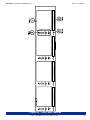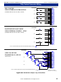
1
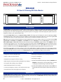
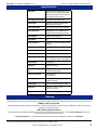
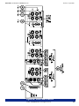
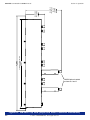
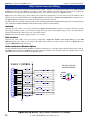
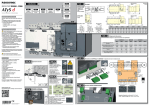
RM-2440
Document P/N 821574 Rev-C
2U Quad LCD Video Monitor
with Four 4" LCD Video Displays,
Eight Composite Video Inputs (on BNC)
with A/B Switching, Eight Loop-Through
Outputs (on BNC), and Option for
Adding SDI Inputs
User Manual
CONTENTS
Title and Contents .................................................................... 1
Important Safety Instructions and Introduction .......................................... 2
Section 1: General Features and Specifications........ 3
Description, Features, Applications ..................................................... 4
Specifications and Options ...................................................................... 5
Installation ............................................................................................... 6
Section 2: Operation ................................................................. 7
Front Panel Features .............................................................................. 8
Rear Panel Features ................................................................................ 10
Section 3: Technical Information ....................................... 13
Tally Control Connector Wiring ............................................................... 14
© 2006 Wohler Technologies Inc. ALL rights reserved
1
Important Safety Instructions
1)
Read these instructions.
2)
Keep these instructions.
3)
Heed all warnings.
4)
Follow all instructions.
5)
Do not use this apparatus near water.
6)
Clean only with dry cloth.
7)
Do not block any ventilation openings. Install in accordance with the manufacturer's instructions.
8)
Do not install near any heat source such as radiators, heat registers, stoves, or other apparatus (including
amplifiers) that produce heat.
9)
Do not defeat the safety purpose of the polarized or grounding-type plug. A polarized plug has two blades
with one wider than the other. A grounding type plug has two blades and a third grounding prong. The
wide blade or the third prong are provided for your safety. If the provided plug does not fit into your outlet,
consult an electrician for replacement of the obsolete outlet.
10) Protect the power cord from being walked on or pinched, particularly at plugs convenience receptacles
and the point where they exit from the apparatus.
11) Only use attachments/accessories specified by the manufacturer.
12) Use only with the cart stand, tripod, bracket, or table specified by the manufacturer, or sold with the
apparatus. When a cart is used, use caution when moving the cart/apparatus combination to avoid injury
from tip-over.
13) Unplug this apparatus during lightning storms or when unused for long periods of time.
14) Refer all servicing to qualified service personnel. Servicing is required when the apparatus has been
damaged in any way, such as when power-supply cord or plug is damaged, liquid has been spilled or
objects have fallen into the apparatus, the apparatus has been exposed to rain or moisture, does not
operate normally, or has been dropped.
15) Do not expose this apparatus to rain or moisture.
16) The apparatus shall be connected to a mains socket outlet with a protective earthing connection.
CAUTION!
In products featuring an audio amplifier and speakers, the surface at the side of the
unit, where the audio amplifier heat sink is internally attached, may get very hot after
extended operation. When operating the unit excercise caution when touching this
surface and ensure that external materials which may be adversely affected by heat
are not in contact with it. There is a Hot Surface label (see diagram) attached to the
aforementioned surface of the product.
Introduction
Congratulations on your selection of a PANORAMAdtv product. We are confident it represents the best performance and value
available, and we guarantee your satisfaction with it.
If you have questions or comments you may contact us at:
Wohler Technologies, Inc.
31055 Huntwood Avenue
Hayward, CA 94544
Phone: (510) 870-0810
Fax: (510) 870-0811
US Toll-Free: 1-888-596-4537
www.panoramadtv.com
2
[email protected]
© 2007 Wohler Technologies, Inc. ALL rights reserved
RM-2440 User Manual P/N 821574 Rev-C
Section 1
General Features
and Specifications
Installation
Description
Features
Applications
Specifications
Options
© 2006 PANORAMAdtv ALL rights reserved
3
Section 1: General Features and Specifications
RM-2440 User Manual P/N 821574 Rev-C
RM-2440
2U Quad LCD Analog/SDI Video Monitor
1
1A
1B
2A
2
2B
3
3A
3B
4A
4
4B
BRIGHT
BRIGHT
BRIGHT
BRIGHT
CONTRAST
CONTRAST
CONTRAST
CONTRAST
COLOR
COLOR
COLOR
COLOR
TINT
TINT
TINT
TINT
RM-2440
RM-2440 Front Panel
Description
The RM-2440 is a color video monitor in a 2RU chassis containing four 4" (100mm) Active Matrix TFT LCD displays. Each LCD
is back lit with a cold cathode fluorescent tube. The LCD’s are mounted in a rotatable cylinder, which allows the operator to rotate
the display array ±55° in the vertical plane to provide optimum operator viewing angles. Each LCD display has separate controls for
brightness, contrast, color, and tint (NTSC only).
The standard RM-2440 features two composite analog (CVBS) video inputs per LCD display for a total of eight inputs (NTSC
and PAL autosensing). One of the two inputs (per display) is selected using a front panel A/B switch. Each of the eight CVBS
video inputs has a passive loop-through on a BNC connector and a 75 Ohm/Hi-Z termination select switch.
SDI signals may be monitored with installation of a field-installable option (one per display). There are two models of optional SDI
Input Module; the RMSDI-1 and RMSDI-2. The RMSDI-2 features an SDI input, a reclocked SDI output, a converted (from
SDI) CVBS output, an SDI Lock indication LED, and autosensing of NTSC/PAL signal formats. The RMSDI-1 offers a
somewhat reduced feature set for cost savings and is identical except that it lacks the SDI Output and requires manually setting a
switch for NTSC/PAL formatting. Each installed SDI Input module disables the second (or B) CVBS video input in the section in
which it is installed. Selection of the SDI Input Module(s) is accomplished using the appropriate front panel A/B switch.
Each display also features a tri-color (red/green/yellow) tally LED indicator. A DB-25 connector on the rear panel is used to
interface the RM-2440 with your facilities tally system. An optional field-installable audio indication module (AIM-1) can be
plugged into the tally connector in order to use the RM-2440 tally LEDs for indication of audio presence and loss.
Features
• Compact 2U rack size and lightweight
• Minimal power dissipation for low operating temperatures
• Quad 4" LCD color video monitor
• Low power consumption
• Adjustable screen angle for efficient viewing
• External power supply
• Eight composite video inputs with loop-through (two per display)
• Optional (field installable) SDI input module(s) (RMSDI-1 and
RMSDI-2) with SDI input, reclocked SDI output, converted
CVBS output, and autosensing of NTSC/PAL formats
• Front panel A/B switching (one per display)
• Dual standard NTSC/PAL auto-sensing
• Controls for brightness, contrast, color, and tint (NTSC only)
• Optional (field installable) audio indication module (AIM-1) for
using the RM monitor tally lights to indicate audio presence or
loss.
• Four Red/Green/Yellow tally lights (one per display)
Applications
The RM-2440 is ideal for confidence video monitoring of multiple video feeds for mobile trucks, news and transmission control rooms,
duplication and post production applications. Built and rigorously tested in the USA, the RM-2440 is backed by a strong warranty (see
page 2) and a “Satisfaction Guaranteed” return policy.
4
© 2006 PANORAMAdtv ALL rights reserved
RM-2440 User Manual P/N 821574 Rev-C
Section 1: General Features and Specifications
Specifications
Video Input:
Eight composite (CVBS) video inputs
(two per screen) with A/B select. Each
screen has provisions for an optional
input module as the "B" input.
Video Input Termination:
Selectable 75 ohm termination
Video Output:
Eight loop-through composite video
outputs (two per screen)
Screen Type / Size:
Active matrix TFT-LCD / 4" diagonal
Source Selection:
A/B Selection of 2x CVBS IN (or 1x
CVBS & 1x SDI module) per screen
Display Modes:
NTSC/PAL autosensing
Aspect Ratio:
4:3
Picture Controls:
Brightness, chroma, tint (NTSC only),
contrast
Resolution (dots x lines):
960 x 234
Dot Pitch:
0.171 x 0.264 mm
Color Configuration:
RGB stripe
Viewing Angle:
top = 10 degrees, bottom = 30 degrees
left = 45 degrees, right = 45 degrees
Contrast Ratio:
150 (typical)
Brightness:
300 NITs (cd/m^2)
LCD Lamp Life (at 50% of 10,000 hours (minimum)
life):
15,000 hours (average)
Power Consumption:
24 watt (typical)
42 watt (max)
Power Supply:
110/220 VAC-12VDC, external power
supply (included)
Chassis Type:
2U, 19" rack mounting (EIA-310D)
Dimensions:
18.8"W x 3.2"D x 3.4"H
(483 x 81 x 89 mm)
Weight:
6 pounds (2.72 kg)
Options
RMSDI-1 (SDI) Input Option
Field installable SDI input module with SDI input, composite output of SDI input, SDI Lock LED, and manual NTSC/PAL switch
RMSDI-1 (SDI) Input Option
Field installable SDI input module with SDI input, SDI Re-clocked output, composite output of SDI input, SDI Lock LED, and
automatic NTSC/PAL sensing
AIM-1 Audio Indication Option
Field Installable Audio Indication Module (plugs into rear D-SUB and uses tally LEDs). Contact PANORAMAdtv directly for
more information about this optional feature.
Call PANORAMAdtv or your distributor for ordering details on any of the options available for the RM-2440.
Units are designed to meet, at time of manufacture, all currently applicable product safety and EMC requirements, such as those of
UL and CE. Features and specifications subject to improvement without notice.
© 2006 PANORAMAdtv ALL rights reserved
5
RM-2440 User Manual P/N 821574 Rev-C
Section 1: General Features and Specifications
Installation
Unpacking
Unpack the RM-2440 unit from the shipping container and inspect all articles for shipping damage. If you find any damage,
notify the shipping carrier immediately for claims adjustments. Compare the shipping box contents to the packing slip. Contact
our PANORAMAdtv sales representative if there are any unexplained shortages.
Cooling and Airflow
No special physical mounting considerations are necessary regarding unit heat dissipation except under adverse conditions. Provided
the ambient temperature inside the mounting enclosure does not exceed 40 degrees Celsius (104 degrees Fahrenheit), adjacent devices
can be rack mounted (or stacked) in proximity to the RM-2440 unit. If the above temperature is exceeded, allow a 1RU (1.75”/25mm)
space above and below the unit for air circulation.
Rack Mounting
The RM-2440 unit rack mounts in a standard EIA-310-D specification 19”/483 mm rack and needs only 2RU of space. Allow
sufficient space at the unit rear for connector and cable clearance (approximately 4”/102mm). The RM-2440 unit rack
mounts from the front panel support rails. Rear support is not required.
See Figure-2c on page 12 for RM-2440 rack, standard connector, and optional RMSDI module connector clearance
dimensions.
General Installation Recommendations
Recommended Cables: Recommended cable type for Composite (analog) or SDI video signals is: Belden 1694A (or
equivalent).
6
© 2006 PANORAMAdtv ALL rights reserved
RM-2440 User Manual P/N 821574 Rev-C
Section 2
Operation
Front Panel Features
Rear Panel Features
© 2006 PANORAMAdtv ALL rights reserved
7
Section 2: Operation
RM-2440 User Manual P/N 821574 Rev-C
Front Panel Features
Please refer to Figure-2a on the following page to familiarize yourself with the front panel features of the RM-2440 unit. The
following sections describe these features and are referenced, by number, to Figure-2a.
1
LCD Video Display (1-4)
View input video sources here. Select one of two source inputs for each display by setting the A/B Source Select Switch
(Item 4) to the desired input. Screen image parameters are adjustable by four manual controls (Item 2).
2
LCD Video Display Controls (1-4)
Each LCD video display can be adjusted separately using these four image controls:
• BRT - Brightness; adjust for desired screen brightness.
• CNT - Contrast; adjust for desired image scene, dark-to-bright contrast.
• COL - Color Saturation; adjust for desired amount of image color saturation.
• TNT - Tint (Hue); adjust for desired image color hue (NTSC only).
3
Tally Indication LED (1-4)
This tri-color LED can glow RED, GREEN, or YELLOW to indicate tally status associated with the signal displayed. Refer
to pages 14 and 15 for tally connection details.
An optional audio indication module (AIM-1) may be installed into the Tally Control Connector on the rear panel (Item
E, page 10), which allows these LEDs to act as audio indicator lights. Please contact PANORAMAdtv for more information
about this optional feature.
4
A/B Source Select Switch (1-4)
In a standard configuration, this switch selects between the primary CVBS (A) and secondary CVBS (B) video source
inputs for the associated I/O Section.
If an optional input module (RMSDI-1 or RMSDI-2) is installed in an I/O Section, the associated switch selects between
the primary CVBS Input (A) source and the installed optional input video source (B).
8
© 2006 PANORAMAdtv ALL rights reserved
RM-2440 User Manual P/N 821574 Rev-C
Section 2: Operation
Figure-2a: Front Panel Features
© 2006 PANORAMAdtv ALL rights reserved
9
RM-2440 User Manual P/N 821574 Rev-C
Section 2: Operation
Rear Panel Features
Please refer to Figure-2b on the following page to familiarize yourself with the rear panel features of the RM-2440 unit. The
following sections describe these features and are referenced, by letter, to Figure-2b. See Figure-2c on page 12 for a top view of
the RM-2440 showing rear panel connector clearance dimensions.
Note about options: Figure-2b shows each of the two optional SDI Input Modules (RMSDI-1 and RMSDI-2) installed in
channels 1 and 2 and no option installed in channels 3 and 4. The SDI Input Modules may be installed in any combination (one per
display). Options are selected for monitoring by setting the associated A/B Source Select Switch on the front panel (Item 4, page
8) to the B position. For each section with an SDI Input Module installed, the CVBS Loop-Through Connector (Item C) will
output CVBS signals as converted from the SDI input. In any I/O section with an SDI Input Module option installed, the B CVBS
Input BNC connector should NOT be used, and it is recommended that it be covered with a connector cap to prevent its use.
A
Termination Switch (1A - 4A, 1B - 4B)
This switch terminates the CVBS Input Connector as required by your configuration. If you supply downstream
equipment from the CVBS Loop-Through Connector (Item C), then set this switch to the Hi-Z position. If not, set
Ω position.
this switch to the 75Ω
B
CVBS Input (IN) Connector (1A - 4A, 1B - 4B)
CVBS video signals may be connected here. NTSC or PAL standards are accommodated automatically. If signals are connected
at both the A and B inputs within the same I/O section, use the A/B Source Select Switch (Item 4, page 8) to select between the
two. Note: If an SDI Input Option module is installed in a B section, do NOT use the associated B CVBS input.
C
CVBS Loop-Through (OUT) Connector (1A - 4A, 1B - 4B)
Signal-through connections to downstream equipment are supplied at these BNC connectors. If you supply downstream
equipment from these connectors, ensure that you set the Termination Switch (Item A) according to your configuration.
Note that if an SDI Input Module (Item G) is installed in the same I/O section, this connector outputs a CVBS signal as
converted from the SDI Input Connector (Item Gc).
D
Option Connector (1-4)
This DE9 (9-pin) female connector allows you easily install an optional SDI Input Module (Item G).
E
Tally Control Connector
This 25-pin subminiature female “D” connector allows you to use the four front panel Tally Indication LEDs (Item 3,
page 10). Full connection instructions are described on pages 14 and 15.
F
Power Connector
Attach the supplied 110/220-12V external power supply between this connector and mains power.
G
Optional SDI Input Modules (RMSDI-1 and RMSDI-2)
There are two models of optional SDI Input Module; the RMSDI-1 and RMSDI-2. They are identical except that the
RMSDI-1 does not feature a SDI Output Connector (Item Gb) and must use the 525/625 Select Switch (Item Ge) to
select the NTSC/PAL format of the input signal (the RMSDI-2 does this automatically).
Note: See Figure-2c on page 12 for depth clearance dimensions of RM-2440 when RMSDI option modules are installed.
10
Ga
CVBS Output (Converted From SDI Input) Connector
When an optional RMSDI-1 or RMSDI-2 module is installed, this connector outputs CVBS signals as converted from the
Ω.
SDI Input Connector (Item Gc). If this output is NOT used, set the associated Termination Switch (Item A) to 75Ω
Gb
SDI Output Connector (RMSDI-2 Only)
SDI signal-through connections to down-stream equipment are supplied at this BNC connector. This connector
supplies a reclocked replica of the SDI input signal.
Gc
SDI Input Connector
Ω.
Connect SDI signals to this female BNC connector, which is terminated at 75Ω
Gd
SDI Lock Indication LED (GREEN)
When a valid (and locked) SDI signal is received at the SDI Input Connector (Item Gc) this LED lights GREEN.
Ge
525/625 (NTSC/PAL) Select Switch (RMSDI-1 Only)
On the RMSDI-1 (only), this switch is used to manually select for NTSC (525 line) or PAL (625 line) input signals.
Set the switch to the RIGHT to select PAL (625 lines), to the LEFT to select NTSC (525 lines).
© 2006 PANORAMAdtv ALL rights reserved
RM-2440 User Manual P/N 821574 Rev-C
Section 2: Operation
Figure-2b: Rear Panel Features
© 2006 PANORAMAdtv ALL rights reserved
11
RM-2440 User Manual P/N 821574 Rev-C
Section 2: Operation
RMSDI
Option
Connector
Clearence
Stnd. Conn.
Clearence
Internal Rack Clearence
RMSDI Options installed
at channels 1 and 2.
Figure-2c: RM-2440 Top View (Depth and Width Clearance Dimensions)
12
© 2006 PANORAMAdtv ALL rights reserved
RM-2440 User Manual P/N 821574 Rev-C
Section 3
Technical Information
Tally Control Connector Wiring
NOTE:
Wohler Technologies,
Inc.
PCB layout and schematic
support
documentation
is available upon request.
31055
Huntwood
Avenue
Hayward, CA 94544
PANORAMAdtv
Fax: (510) 870-0811
31055 Huntwood Avenue
US Toll-Free: 1-888-596-4537
Hayward, CA 94544
www.panoramadtv.com [email protected]
1-888-596-4537 Fax: (510) 870-0811
web: www.panoramadtv.com
e-mail: [email protected]
Phone: (510) 870-0810
© 2006 PANORAMAdtv ALL rights reserved
13
RM-2440 User Manual P/N 821574 Rev-C
Section 3: Technical Information
Tally Control Connector Wiring
A front panel tally LED is associated with each LCD monitor. Interface is provided to the LEDs via the Tally Control
Connector on the rear panel (Item E, page 10). Tri-color (RED, GREEN, and YELLOW) tally indications are possible by
activating the red and green LED sections simultaneously. For connection details, see Figure-3a below .
Figure 3-b, on the facing page, shows sample tally connection configurations. You can operate the Tally LEDs by three
methods. The three tutorial examples showing Dry Closure (internal power), Positive True Logic Drive (external power),
and Open Collector (transistors as switches) are illustrated to show basic operation.
The Tally indicators are capable of displaying three colors. Illuminating the RED or GREEN LEDs separately will result in that tally
color. Illuminate the RED and GREEN LEDs simultaneously to achieve a YELLOW tally.
Isolated
Operating the Tally LEDs in an isolated configuration (Figure-3b: Dry Closure) requires an external (customer provided)
power supply and tally system. If your facility currently has a tally system with companion power source, use this method to
integrate the RM Monitor tallies with your existing tally matrix.
NOTE: Ensure the LED power supply provides +5 to +12VDC.
Non-Isolated
Operating the Tally LEDs in the non-isolated configuration (Figure-3b: Positive True Logic Drive) uses the RM
Monitor internal power supply to provide the tally LED voltage. Connect your tally closures as shown in Figure-3b to the
respective RM Monitor tally connections.
Audio Indication Module Option
An optional audio indication module (AIM-1) is available to enable the use of the tally LEDs to indicate audio presence and loss.
The AIM-1 module installs onto the RM rear panel tally connector and then receives the audio input from a seperate cable. Contact
PANORAMAdtv for more information concerning this option.
CIRCUIT IN MON4-3
+12V
TALLY CONTROL
DB25 FEM
PC R/A FEM
2
1
1
390
1/4W 5%
1
2
1
150
3
4
5
390
1/4W 5%
5
6
7
7
8
TR3
TC3
TG3
8
220
1
GREEN
TGn
TRn
RED
TG2
6
150
TR2
TC2
220
1
2
3
4
150
390
1/4W 5%
2
TG1
220
1
TR1
TC1
2
390
1/4W 5%
2
2
220
S
1
14
2
15
3
16
4
17
5
18
6
19
7
20
8
21
9
22
10
23
11
24
12
25
13
FRONT PANEL LED
ONE PER MONITOR
TR4
TC4
TG4
150
390
1/4W 5%
Figure-3a: RM Monitor Tally Control Connector Pin Function
14
© 2006 PANORAMAdtv ALL rights reserved
TCn
RM-2440 User Manual P/N 821574 Rev-C
Section 3: Technical Information
CHANNEL
DRY CLOSURE
1
14
2
15
3
16
4
17
5
18
6
19
7
20
8
21
9
22
10
23
11
24
12
25
13
RED
USING INTERNAL POWER SOURCE
1
GRN
(EITHER/OR BOTH LEDS ON IS OK, BOTH = YELLOW)
RED
2
GRN
RED
3
GRN
RED
4
GRN
USER CABLE CONNECTOR IS MALE
Tally Control Connector Wiring
CHANNEL
1
14
2
15
3
16
4
17
5
18
6
19
7
20
8
21
9
22
10
23
11
24
12
25
13
+V
RED
POSITIVE TRUE LOGIC DRIVE
1
GRN
USING EXTERNAL POWER 5 - 12VDC
(EITHER/OR BOTH LEDS ON IS OK, BOTH = YELLOW)
RED
2
GRN
RED
3
GRN
RED
4
GRN
TALLY CONTROL GROUND IS ISOLATED FROM MON GROUND
USER CABLE CONNECTOR IS MALE
DB25 MALE
DB25 MALE
TALLY CONTROL GROUND IS ISOLATED FROM RM GROUND
OPEN COLLECTOR
1
C
NPN
G
R
RED
GRN
TRANSISTOR ON =LED ON
(ONE LED ONLY)
2
C
NPN
G
R
RED
GRN
3
C
NPN
G
R
RED
GRN
4
NPN
C
G
R
RED
GRN
1
14
2
15
3
16
4
17
5
18
6
19
7
20
8
21
9
22
10
23
11
24
12
25
13
USER CABLE CONNECTOR IS MALE
USE ONLY ONE LED
CHOOSE LED BY JUMPING R (RED) OR G (GREEN) TO C.
CHANNEL
DB25 MALE
TALLY CONTROL GROUND IS NOT ISOLATED FROM RM GROUND
TALLY CONTROL GROUND IS NOT ISOLATED FROM MON3-x GROUND
COMMONS ARE CONNECTED
INTERNALLY, ONLY ONE IS REQ'D
Figure-3b: RM Monitor Sample Tally Connections
© 2006 PANORAMAdtv ALL rights reserved
15
RM-2440 User Manual P/N 821574 Rev-C
PANORAMAdtv
Wohler31055
Technologies,
Inc.
Huntwood Avenue
31055 Hayward,
Huntwood
CA Avenue
94544
Hayward,
CA
94544
1-888-596-4537
Phone: (510) 870-0810
(510) 870-0811
Fax: (510)Fax:
870-0811
USweb:
Toll-Free:
1-888-596-4537
www.panoramadtv.com
www.panoramadtv.com
[email protected]
e-mail: [email protected]
16
© 2006 PANORAMAdtv ALL rights reserved