Download Touch-it Series - Wohler Technologies
Transcript
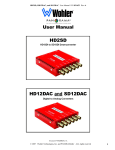
Touch-it Series
(Document P/N 821646 Rev-A)
3U Dual High-Resolution LCD
Video Display Monitor and Router
with Two 7" Wide High-Resolution LCD Video Displays
(one Thumbnail Select Display, one Target Display),
Twelve CVBS Video Inputs/Active Video Loop Outputs
(on BNC), with Optional Audio Monitoring and Outputs
User Manual
CONTENTS
Title and Contents .................................................................... 1
Important Safety Instructions and Introduction ......................................... 2
Section 1: General Features and Specifications.......... 3
Warranty for PANORAMAdtv Products ................................................. 3
Description and Features ......................................................................... 4
Applications and Specifications ................................................................ 5
LCD Display Optical Characteristics ........................................................ 6
Installation ............................................................................................... 6
Section 2: Operation .................................................................. 7
Front Panel Features ............................................................................... 8
Rear Panel Features ................................................................................. 10
Section 3: Information .............................................................. 15
Touch-it Series Video Block Diagram .................................................... 16
Touch-it Plus Audio Block Diagram ....................................................... 17
© 2006 Wohler Technologies Inc. ALL rights reserved
1
Important Safety Instructions
1)
Read these instructions.
2)
Keep these instructions.
3)
Heed all warnings.
4)
Follow all instructions.
5)
Do not use this apparatus near water.
6)
Clean only with dry cloth.
7)
Do not block any ventilation openings. Install in accordance with the manufacturer's instructions.
8)
Do not install near any heat source such as radiators, heat registers, stoves, or other apparatus (including
amplifiers) that produce heat.
9)
Do not defeat the safety purpose of the polarized or grounding-type plug. A polarized plug has two blades
with one wider than the other. A grounding type plug has two blades and a third grounding prong. The
wide blade or the third prong are provided for your safety. If the provided plug does not fit into your outlet,
consult an electrician for replacement of the obsolete outlet.
10) Protect the power cord from being walked on or pinched, particularly at plugs convenience receptacles
and the point where they exit from the apparatus.
11) Only use attachments/accessories specified by the manufacturer.
12) Use only with the cart stand, tripod, bracket, or table specified by the manufacturer, or sold with the
apparatus. When a cart is used, use caution when moving the cart/apparatus combination to avoid injury
from tip-over.
13) Unplug this apparatus during lightning storms or when unused for long periods of time.
14) Refer all servicing to qualified service personnel. Servicing is required when the apparatus has been
damaged in any way, such as when power-supply cord or plug is damaged, liquid has been spilled or
objects have fallen into the apparatus, the apparatus has been exposed to rain or moisture, does not
operate normally, or has been dropped.
15) Do not expose this apparatus to rain or moisture.
16) The apparatus shall be connected to a mains socket outlet with a protective earthing connection.
CAUTION!
In products featuring an audio amplifier and speakers, the surface at the side of the
unit, where the audio amplifier heat sink is internally attached, may get very hot after
extended operation. When operating the unit excercise caution when touching this
surface and ensure that external materials which may be adversely affected by heat
are not in contact with it. There is a Hot Surface label (see diagram) attached to the
aforementioned surface of the product.
Introduction
Congratulations on your selection of a PANORAMAdtv product. We are confident it represents the best performance and value
available, and we guarantee your satisfaction with it.
If you have questions or comments you may contact us at:
Wohler Technologies, Inc.
31055 Huntwood Avenue
Hayward, CA 94544
Phone: (510) 870-0810
Fax: (510) 870-0811
US Toll-Free: 1-888-596-4537
www.panoramadtv.com
2
[email protected]
© 2007 Wohler Technologies, Inc. ALL rights reserved
Touch-it Series User Manual P/N 821646 Rev-A
Section 1
General Features
and Specifications
Description
Features
Applications
General Specifications
Installation
© 2006 PANORAMAdtv ALL rights reserved
3
Section 1: General Features and Specifications
Touch-it Series User Manual P/N 821646 Rev-A
Touch-it Series
3U Dual Display High-Resolution Video Monitor and Router
TOUCH-IT Front Panel
TOUCH-IT PLUS Front Panel
Description
The Touch-it Series from Wohler Technologies, offers a simple and easy way to monitor multi-channel video, provide routing,
as well as an external screen output in a compact and versatile space saving 3RU. The touch screen video monitor is ideal for multicamera live shoots, machine rooms, and outside broadcasts.
All Touch-it Series models feature dual high resolution 7” LCD panels, offering video confidence monitoring for up to 12 channels
of composite video. The left 7” monitor displays twelve 1.8” "thumbnail" images, and when one of these is touched, that image
appears on right screen at full size and its signal is also sent to a video output BNC connector. LCD backlights may be turned off
to conserve power and backlight life leaving all other functions powered.
The rear panel of all models feature twelve video inputs on BNC connectors, twelve active loop-through outputs on BNC connectors
(negating the need for termination selection), and two selected video outputs on BNC connectors. The included external power
suppy is plugged into the unit via industry standard DIN connector.
The Touch- it Plus model is also available with audio monitoring of twelve stereo analog audio inputs on DB-25 connectors, left
and right internal speakers, and routing functions. The monitored audio follows the selected video output on XLR connectors.
There are switches for setting audio line out logic, attenuation, and volume pre/post selection.
Features
• Fits in a 3U standard 19" rack space with shallow depth for installation in tight spaces
• Dual 7” LCD high resolution color video monitors
• Left monitor features twelve "thumbnail' images of available video channels for monitoring; touching a thumbnail image
selects that channel for monitoring fullsize from the right "target" display and for routing from the selected out connectors.
• Selectable 4:3 and 16:9 aspect ratio for "target" display and 4:3 fixed aspect ratio for thumbnail displays
• Front panel controls for brightness, contrast, tint, color of "target' display. Video controls are set and memorized for each of
the twelve video inputs.
• Twelve CVBS video inputs on BNC connectors and twelve CVBS video active loop-through outputs on BNC connectors
(active loop-through outputs do not require termination selection)
• Plus model features twelve stereo analog audio inputs on three DB-25 connectors, selected audio outputs on two XLR
connectors, left/right internal speakers, and a headphone output. Audio selection "follows" video selection.
• LCD display backlights may be turned off seperately from main unit power.
• Low power consumption and minimal power dissipation for a low operating temperature
• External universal AC mains power supply plugs into industry standard DIN connector on rear panel
4
© 2006 PANORAMAdtv ALL rights reserved
Section 1: General Features and Specifications
Touch-it Series User Manual P/N 821646 Rev-A
Applications
The Touch-it Series is ideal for video monitoring for mobile trucks, news and transmission control rooms, duplication and post
production applications. Built and rigorously tested in the USA, the Touch-it Series is backed by a strong warranty and a “Satisfaction
Guaranteed” return policy.
General Specifications
Display Size (diagonal):
2 x 7.0" (17.8 cm)
Display Type:
High-resolution TFT LCD , Transmissive
Video Formats:
NTSC/PAL autosensing
Signal Input Conn/Type:
75 ohm BNC / CVBS (NTSC or PAL)
Display Image Controls:
Brightness, contrast, color, tint, aspect
ratio ("target" display only)
Aspect Ratio:
Target Display = 16:9 or 4:3
Thumbnail Displays (x12) = 4:3 each
Active Area (HxV):
155.00 x 87.12 (mm)
Resolution (dots x lines):
854 Pixels X 3 (RGB Dots) X 480
Lines (1.2M “Megadots”)
Dot Pitch (HxV):
0.0605 x 0.1815 (mm)
Pixel response Time:
7 ms rising (typ.); 18 ms falling (typ.)
Color Configuration:
RGB Stripe
Color Numbers:
262,000
Viewing Angle:
top=50°, bottom=60°, left=65°, right=65°
Contrast Ratio:
450 (typ.)
Brightness:
400 (typ.) NITs (cd/m2)
LCD Lamp Life:
15,000 hours (avg.). to specified
reduction
Power Consumption:
40W
Power Supply:
100 to 240VAC, 47 to 63Hz, universal
input, external, CE & UL approved
Chassis Type:
3U, 19” rack mounting (EIA-310D)
Dimensions (HxWxD):
5.25" x 19" x 4.25" (excluding
connectors)
Weight:
9.5 lbs. (excluding external power
supply)
Units are designed to meet, at time of manufacture, all currently applicable product safety and EMC requirements, such as those of CE.
Features and specifications subject to improvement without notice.
© 2006 PANORAMAdtv ALL rights reserved
5
Touch-it Series User Manual P/N 821646 Rev-A
Section 1: General Features and Specifications
LCD Display Optical Characteristics
Installation
Unpacking
Unpack the Touch-it Series unit from the shipping container and inspect all articles for shipping damage. If you find any
damage, notify the shipping carrier immediately for claims adjustments. Compare the shipping box contents to the packing
slip. Contact our PANORAMAdtv sales representative if there are any unexplained shortages.
Cooling and Airflow
No special physical mounting considerations are necessary regarding unit heat dissipation except under adverse conditions. Provided
the ambient temperature inside the mounting enclosure does not exceed 40 degrees Celsius (104 degrees Fahrenheit), adjacent devices
can be rack mounted (or stacked) in proximity to the unit. If the above temperature is exceeded, allow a 1RU (1.75”/44.45mm) space
above and below the unit for air circulation.
Rack Mounting
The Touch-it Series unit half-rack mounts in a standard 19" rack.
General Installation Recommendations
Recommended Video Cable Type: Belden 8281 or Belden 1694A (or equivalent).
Recommended Audio Cable Type: Belden 9451 (or equivalent).
6
© 2006 PANORAMAdtv ALL rights reserved
Touch-it Series User Manual P/N 821646 Rev-A
Section 2
Operation
Front Panel Features
© 2006 PANORAMAdtv ALL rights reserved
7
Touch-it Series User Manual P/N 821646 Rev-A
Section 2: Operation
Front Panel Features
Please refer to Figure-2a on the facing page to familiarize yourself with the front panel features of the Touch-it Series unit. The
following sections describe these functions and are referenced, by number, to Figure-2a.
1
Headphone Jack (Plus model only)
The Touch-it Plus model (only) features this jack, which accepts a standard 1/8” mini stereo phone type stereo plug.
Select the headphone audio sources as you would for the internal speakers. When you plug in headphones the internal
speakers will mute, but all other audio outputs continue to function as selected.
2
Internal Speakers (Plus model only)
The Touch-it Plus model (only) features these two mid-range speakers (left and right) to accomodate the two audio
channels that may be monitored from the selected input.
3
Line/Speaker Switch (Plus model only)
This Line/Speaker Switch is used to route the audio to either the line out, internal speakers, or both. The selection is
modified by the setting of the rear panel Line Output Status Switch (Item B, page 12). See below for settings:
SPEAKERS (AMBER LED):
Selected audio signals are routed to the internal speakers (or connected headphones) and signals to the Selected
Line Out XLR connectors are muted. However, if the Line Output Status Switch is set to ALWAYS ON, then the
audio is routed to both the internal speakers (or connected headphones) and the Selected Line Out XLR connectors.
LINE (RED LED):
Audio signals are routed only to the two Selected Line Out XLR connectors and signals to the two internal
speakers (or connected headphones) are muted.
4
Touch Panel Display
This high-resolution 7" LCD video screen displays "thumbnail" images of the twelve input video channels. One of twelve
input video channels is selected by lightly touching the "thumbnail" image with a fingertip, thus routing it for full size
monitoring from the Video Target Display (Item 5) and for output from the rear panel Selected Video Output BNC
connectors (Item G, page 12). The border around the thumbnail image will highlight RED to indicate it is selected. Note
that overall display parameters are not adjustable, however each thumbnail image will be adjusted together with the target screen
for each selected input. Channel designations for each of the twelve thumbnail displays on this screen are as follows:
5
1
2
3
4
5
6
7
8
9
10
11
12
NOTE: The last selected input channel will be written to memory following a 10 second
timeout. This allows the last selection to be restored following a power cycle or failure.
Video Target Display
This high-resolution 7" LCD video screen displays the "target" image as selected from the Touch Panel Display (Item
4). When a thumbnail display is selected by touching it, that image is routed for full resolution display from this LCD
while at the same time routing the selected video to the Selected Out BNC connectors on the rear panel (Item G, page
12). Controls for adjusting brightness, contrast, color, tint and aspect ratio (4:3 or 16:9) are to the right of the screen
(Item 9, page 10). Video controls are set and memorized for each of the twelve inputs.
Note that in the Touch-it Plus model, the audio follows the selected video. In other words, audio is monitored from the
particular Audio Input Connector (Item E, page 12) which corrosponds to the currently selected video source shown
in the Video Target Display (channels 1 through 8). If a different video source is selected, then the Audio Input
Connector corrosponding to the new video selection will be selected for monitoring.
6
8
LCD Power Switch and LED
This switch turns both of the video display backlights ON or OFF. The LED above the switch glows GREEN to indicate
backlight power is ON and glows RED to indicate backlight power is OFF. This switch affects only LCD backlight operation;
the unit continues to be powered with all routing functions in full operation regardless of this switch setting, as long as
the unit is connected to active mains power. Note that the Touch Panel Display (Item 4) is disabled when the LCD backlight
power is turned off, though the channel loops and last routed selection remains active at the BNC outputs (and audio XLR
outputs on Touch-It Plus).
© 2006 PANORAMAdtv ALL rights reserved
Touch-it Series User Manual P/N 821646 Rev-A
Touch-It
Plus
Section 2: Operation
Touch-It
Figure-2a: Front Panel Features
© 2006 PANORAMAdtv ALL rights reserved
9
Touch-it Series User Manual P/N 821646 Rev-A
Section 2: Operation
Front Panel Features
7
Balance Control (Plus model only)
This control changes the audio volume balance between the left and right speaker channels.
8
Volume Control (Plus model only)
This controls the volume loudness of the audio reproduced by the left and right speaker channels.
9
Video Display Controls
The Video Target Display (Item 5, page 8) may be adjusted for brightness, contrast, color, tint and aspect ratio (4:3 or
16:9) using these controls. Repeated pressing of the parameter select button (beneath the parameter LEDs) cycles
through each parameter (LEDs glow AMBER to indicate selected parameter). When desired parameter is selected, use the
+ and - buttons to adjust the parameter as required. Each parameter can be reset to the default value by simultaneously
pressing the + and - buttons. All parameters for a given channel can be reset to default by pressing all three buttons ( +, -, and
parameter select) simultaneously.
The new values for adjusted parameters will be written to EEPROM memory following a 10 second time-out or upon selection
of another input channel. This allows for multiple parameter changes to be made prior to writing values to memory.
10
© 2006 PANORAMAdtv ALL rights reserved
Touch-it Series User Manual P/N 821646 Rev-A
Section 2: Operation
Section 2
(Cont.)
Operation
Rear Panel Features
© 2006 PANORAMAdtv ALL rights reserved
11
Touch-it Series User Manual P/N 821646 Rev-A
Section 2: Operation
Rear Panel Features
Please refer to Figure-2b on the facing page to familiarize yourself with the rear panel features of the Touch-it Series unit. The
following sections describe these features and are referenced, by letter, to Figure-2b.
A
Power Connector
Attach the included power cord between this connector and the DIN plug output of the provided 24 volt external power
supply. The LEDs for the LCD Backlight and Line Speaker Switches on the front panel will glow to indicate
operating voltages.
B
Audio Line Output Status Switch (Plus model only)
When this switch is set to ALWAYS, then the Selected Audio Line Output Connectors (Item H) will always output
the selected audio line out signals. If set to F.P. CONTROL, then the Line/Speaker Switch on the front panel (Item
3, page 8) is used to determine if signals are sent to the Selected Audio Line Output Connectors or to the speakers.
C
D
Audio Line Output Volume Switch (Plus model only)
When this switch is set to POST, the front panel volume and balance settings are applied to the signals at the Selected
Audio Line Out Connectors. When this switch is set to PRE, then the volume control and balance settings are not
applied, in which case the signals are sent to the line out connectors at unity gain with the audio input signals.
Audio Line Output Attenuation Switch (Plus model only)
Each of the positions of this switch determines the attenuation of the selected audio signal applied to the Selected Audio
Line Out Connectors (Item X). Selections include 0 dB, -6 dB, -12 dB, or -18 dB.
E
Audio Input Connectors (Plus model only)
Each of these three DB-25 connectors accept eight channels (four stereo pairs) of analog audio for a total of twelve stereo
channels. Channel designations are silk-screened to the left of each connector and correspond to the video input
channels. Note that when a video channel is selected for monitoring, the corresponding audio channel is automatically
selected for monitoring (audio follows video). See the diagram below for pinout designations for these connectors:
F
G
Video Input and Loop-Through Connectors
The twelve video IN BNC input connectors are terminated at 75 ohms and will accept CVBS video signals in either NTSC
or PAL formats. However only one of these two formats can be accepted for all inputs at one time. The default setting
of all twelve inputs is for NTSC formatted signals. But if a PAL formatted signal is connected to the Channel 1 input, the
unit will auto-detect it and re-configure all twelve inputs for PAL formatted signals. Additionally, all signal switching and
routing is timed to occur based on the VBI (Vertical Blanking Interval) of the input signal applied to the Channel 1 input,
therefore it is recommended to always apply an input signal to Channel 1 for clean switching transitions of synchronous
signals.
Signal-through connections to downstream equipment are supplied by the twelve video OUT BNC connectors. These are
active loop-through outputs and so there is no need for termination selection.
Each IN/OUT pair of connectors is identified with a channel number, which is silk-screened above it. In Plus models,
these channel numbers correspond to the channel numbers associated with the Audio Input Connectors (Item E).
Selected Video Output Connectors
Each of these two BNC connectors output the video signal as selected from the front panel Video Thumbnail Display
(Item 4, page 8) and displayed on the Video Target Display (Item 5, page 8). It is by using this function that the
Touch-it unit may be used as a router. Note that in the Plus model, the audio source channel associated with the selected
video source channel is also output from the two Selected Audio Line Output Connectors (Item H). Note that the
selected video output is directly switched from the video inputs and does not have video display control parameters
applied or any processing delay.
H
12
Selected Audio Line Output Connectors (Plus model only)
These two 3-pin male XLR connectors (left and right) output the stereo audio source channel associated with the
selected video source channel. See Items B, C, and D for a description of the switches which modify how the signal is
output from these connectors. Pinouts for this connector are: Pin-1 = GRND (Shield), Pin-2 = HI (+), Pin-3 = LOW (-).
© 2006 PANORAMAdtv ALL rights reserved
Touch-it Series User Manual P/N 821646 Rev-A
Rear Panel Features
Touch-It
Plus
Touch-It
© 2006 PANORAMAdtv ALL rights reserved
13
Touch-it Series User Manual P/N 821646 Rev-A
(This page left intentionally blank)
14
© 2006 PANORAMAdtv ALL rights reserved
Section 2: Operation
Touch-it Series User Manual P/N 821646 Rev-A
Section 3
Technical Information
Touch-it Series Video Block Diagram
Touch-it Plus Audio Block Diagram
© 2006 PANORAMAdtv ALL rights reserved
15
Touch-it Series User Manual P/N 821646 Rev-A
Section 3: Technical Information
Touch-it Series Video Block Diagram
16
© 2006 PANORAMAdtv ALL rights reserved
Touch-it Series User Manual P/N 821646 Rev-A
Section 3: Technical Information
Touch-it Plus Series Audio Block Diagram
© 2006 PANORAMAdtv ALL rights reserved
17
Touch-it Series User Manual P/N 821646 Rev-A
PANORAMAdtv
Wohler
Technologies,
31055
Huntwood Avenue Inc.
31055
Huntwood
Avenue
Hayward,
CA 94544
Hayward,
CA
94544
1-888-596-4537 Fax: (510) 870-0811
Phone: (510)
Fax: (510) 870-0811
web: 870-0810
www.panoramadtv.com
US Toll-Free:
1-888-596-4537
e-mail:
[email protected]
www.panoramadtv.com [email protected]
18
© 2006 PANORAMAdtv ALL rights reserved


