1
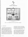
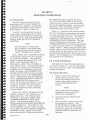
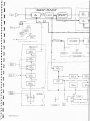
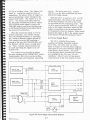
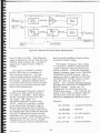
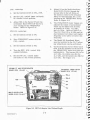
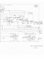
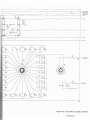
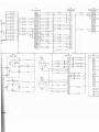
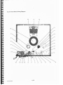
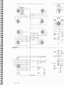
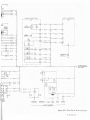
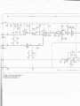
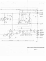
SECTION 4 CIRCUIT DESCRIPTION The 10- MHz signal (± frequency e r r or ) is fed to the Second IF and Discr irninutor board where it is amplified a nd m ixed with a 9.9-MHz signal from the Multi-Osc illator board to form a second IF"and 100 k Hz (± frequency error). This second-IF s ig nal is amplified and applied to the frequency error detector. 4.1 Introduction The circuits of the Model CE-7 Multi Channel Fl\1 Communications Monitor are on five printed circuit boards: the Second IF and Discriminator board (0054), the Power Supply board (0100), the Frequency Error Meter board (010 1), the Harmonic Generator board (0102), and the Multi Oscillator board (0103). Figure 4-1 is the functional block diagram of the CE-7. The 115-vac-supply fuse RP- F2, is on the inside of the rear panel. A squelch detector in the Broadband Mixer or Preselector rectifies th e 10- i\IHz signal. The resulting de voltage is ampli fied and fed to the signal-level detector in the CE-7. If the 10-l\IHz signal exceeds a preset level, the SIG:-\AL LEVEL lamp lights to indicate that a cc urate me asure ments can be made and the frequencyerror detector is energized . The frequency error detector is adjusted to give a zero indication on the FREQUENCY meter when the second IF signal is exactly 100 k Hz . If the frequency of the monitored signal is above or below the frequency selected with the CARRIER FREQUEf\'CY SELECTOR, the input to the frequency-error detector will be exactly the same amount above or below 100 k Hz . The detector output will cause the FREQUE~CY meter to deflect toward the plus (+) or minus (-) side, in dicating the direction and a mount of fre quency error. The CE-7 is basically a multi-channel superheterodyne receiver and a signal generator. In the FREQ. - DEV. MEASURE mode of operation the RF signal, the fre quency and frequency deviation of which are to be measured is applied through the ANT. connector of the RF plug-in that is being used (a Broadband Mixer or one of the three Presel ectcr s) . The RF signal is mixed in the RF plug-in with the local-oscillator signal from the Harmonic Generator board in the CE-7. The local oscillator signal has a frequency that results from mixing the output of a selected crystal oscillator (associated with the selected channel) with the out put of a 10-MHz crystal oscillator. When an R F signal must be measured for carrier-frequency accuracy, the frequency that has been assigned to the transmitter of the RF signal is the same frequency that is selected on the CE-7. Thus, the CE-7 can only monitor a signal for which it has a crystal of appropriate frequency. If the monitored signal is frequency modulated, the modulation will be present in the output of the frequency-error detec tor. This output is demodulated and a sig nal representing the modulation is amplified and fed to either the Model 302 FM Deviation Meter or the Model 301 Oscilloscope. If the Model 302 is used, its FM deviation meter will indicate the peak deviation of the FM signal. On the Model 301 Oscillo scope, the amount of deviation and frequency error will be shown on the CRT . The incoming signal is mixed with the internally generated "standard" or local . oscillator signal. If the transmitter of the incoming signal is on-frequency, the result of this mixing will be an IF of exactly 10-MHz. If the frequency of the incoming signal is not correct, the IF signal will be 10 MHz plus or minus the frequency error. 5601"0015 The CE-7 can be used as a C\V- or FM signal generator but its range i s limited to the frequencies for which crystals are in stalled (if the Model l\1CO-6 Oven-Oscillator is used, the range is extended to include the auxili ary crystals). 4-1