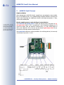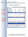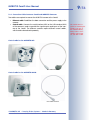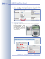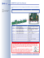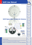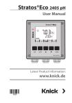
1
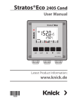
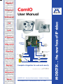
3 mm Beschnitt umlaufend
Megapixel
1280 x 960
software zoom
VGA (640 x 480)
10 fps Mega
-22°F to +140°F
Weatherproof
CamIO
X
MOBOTIX
User Manual
IEEE 802.3af
PoE
network power
even in winter
microphone & speaker
Audio
bi-directional via IP
variable framerates
Video SIP Client
IP Telephony
alarm notify,
cam remote control
MOBOTIX
CamIO
Video motion
5 6
1 2 3 4
8
7 8
10 11
RJ45
13 14 15 16
multiple windows
precision pixel-based
lip-syncronized audio
Recording
event-ringbuffer
30 cams each 30 fps
Line-In
Lamp
Speaker
Speaker
Out1
Live viewing
30 cams at 30 fps
all on one screen
Backlight
safe using CMOS
without mechanical iris
Microphone with
pre-amplifier
23
8
Door
Out2
to
0
V~
/
48 115V
V~ ~
In1
8 to 230 V~ (8 to 48 V~)
In2
8 to 230 V~ (8 to 48 V~)
Complete integration for web and security
Current PDF File:
www.mobotix.com > Support > Manuals
Vandalism-protected
Wall bracket
with cable cover
for RJ45 wall outlet
Robust
no moving parts
fiber glass housing
MOBOTIX AG • Security-Vision-Systems • Made in Germany
www.mobotix.com • [email protected] • 9.11.2007
MOBOTIX ... the new face of IP video
-30°C to +60°C, IP65
no heating necessary
.com
30 Frames/s
Security-Vision-Systems
MOBOTIX CamIO User Manual
Caution
Only qualified personnel may install and open the CamIO and connect it to the mains power; make sure that the relevant regulations of your country are respected!
It is imperative that all electrical wires have been disconnected
from the mains power when working on or servicing the CamIO!
Please also make sure to adhere to the applicable regulations for
this kind of work!
MOBOTIX will not assume any responsibility for damages from
faulty installations or inappropriate use!
Notes
Note:
MOBOTIX offers inexpensive seminars that include a workshop and
practical exercises: Basic Seminar three days, Advanced Seminar two
days.
For more information, see www.mobotix.com
© MOBOTIX AG • Security-Vision-Systems • Made in Germany
www.mobotix.com • [email protected]
1/56
MOBOTIX CamIO User Manual
CamIO User Manual
1
INTRODUCTION
4
1.1
MOBOTIX CamIO Concept
6
1.2 The MOBOTIX CamIO and MOBOTIX Cameras
1.2.1 Functional Overview of the CamIO Models
1.2.2 Connection Cables between CamIO and MOBOTIX Cameras
8
8
9
1.3
1.3.1
1.3.2
1.3.3
1.3.4
1.3.5
1.3.6
1.3.7
1.3.8
1.3.9
Important Notes
Safety Regulations
Cables for the MOBOTIX CamIO
Minimum Load at the Signal Outputs
Safety Notes for Operating the MOBOTIX CamIO
Maximum Cable Lengths
Charging the Rechargeable Battery (CamIO-ACplus)
Weatherproofness, Temperature Range
Cleaning Instructions
Additional Information
10
10
10
11
11
12
12
12
12
12
2
MOUNTING
14
2.1
2.1.1
2.1.2
2.1.3
2.1.4
Delivered Parts, Components, Dimensions and Connectors
Delivered Parts and Components
Wall Mount Foot and Housing
Dimensions and Drilling Template
Connectors and Wiring
14
14
15
16
20
2.2
Information on Connecting the MOBOTIX CamIO
22
2.3 Mounting the CamIO Wall Mount and the Control Cable
2.3.1 Mounting with an M12 Camera
2.3.2 Mounting with an M22 Camera
24
24
26
2.4
2.4.1
2.4.2
2.4.3
28
28
29
32
Mounting the CamIO Housing and Installing the Cables
Mounting the CamIO Housing on the Wall
Power Supply of the CamIO
Ethernet Connection of the CamIO
2.5 Connecting External Components to the CamIO
2.5.1 Connecting External Devices, Sensors and Audio Devices
33
33
2.6 Mounting the Camera on the CamIO
2.6.1 Connecting the Additional Speaker in the Wall Mount Foot
2.6.2 Connecting the Ethernet and the CamIO Control Cables
36
36
37
2.7
2.7.1
2.7.2
2.7.3
Wiring, Fire Prevention, Lightning and Surge Protection
Wiring
Fire Prevention
Lightning and Surge Protection
38
38
38
38
2.8
Accessories, Replacement Parts
40
© MOBOTIX AG • Security-Vision-Systems • Made in Germany
www.mobotix.com • [email protected]
2/56
MOBOTIX CamIO User Manual
3
OPERATION OF THE CAMIO
42
3.1
Activating the CamIO
42
3.2
3.2.1
3.2.2
3.2.3
3.2.4
3.2.5
Configuration Sample
Functional Overview
Terminal Connections of the CamIO
Overview of the Configuration Steps
Configuring the MOBOTIX Camera
Configuring a Softphone
43
43
44
44
45
51
4
TECHNICAL SPECIFICATIONS
52
APPENDIX: DECLARATION OF CONFORMITY
DRILLING TEMPLATE (SCALE 1:1)
Download the latest version of this document as a
PDF file from
www.mobotix.com:
Support > Manuals
Note
Download the latest version of this document as a PDF file from
www.mobotix.com, Support > Manuals.
Information subject to change without notice!
Copyright © 1999-2007 MOBOTIX AG, Kaiserslautern, Germany.
All rights reserved. MOBOTIX, MxPEG and MxControlCenter are worldwide
trademarks of MOBOTIX AG. Microsoft, Windows and Windows Server are registered trademarks of Microsoft Corporation. Apple, the Apple logo, Mac and
Mac OS X are trademarks of Apple Inc. Linux is a trademark of Linus Torvalds.
All other marks and names mentioned herein may be trademarks or registered
trademarks of the respective owners.
© MOBOTIX AG • Security-Vision-Systems • Made in Germany
www.mobotix.com • [email protected]
MOBOTIX CamIO User Manual
Notes
© MOBOTIX AG • Security-Vision-Systems • Made in Germany
www.mobotix.com • [email protected]
3/56
4/56
MOBOTIX CamIO User Manual
1
All CamIO models can be
used with the MOBOTIX
M12 and M22 cameras
(IT and Secure models).
The CamIO can switch
Ohm resistive loads with
max. 5 A, (max. 500 W
lamps at 230 V or
300 W lamps at 115 V).
INTRODUCTION
The MOBOTIX CamIO is the expansion box for connecting the MOBOTIX cameras
M12 and M22M (IT and Secure models). In the security and home automation
fields, the CamIO is the ideal supplement to the MOBOTIX cameras, if you want to
switch lamps, doors, control wires, pushbuttons or other external devices, evaluate
other sensors than those in the camera or use external audio devices (M12 models
only).
An external device (e.g. a lamp) connected to the CamIO-AC/ACplus can be
powered directly by the CamIO and is switched on or off using the first signal out
put of the MOBOTIX camera. The second signal output can be used for potential
free switching of another external device (e.g. door opener; max. 230V~ or 48V~/
68V=, depending on the CamIO model). This signal output can also be used to
connect the MOBOTIX camera to the input of an alarm system, for example.
You can also attach external sensors to the MOBOTIX camera via the CamIO, e.g.
to evaluate remote sensors, such as light barriers, reed switches, external PIR sensors or the output of an alarm system.
© MOBOTIX AG • Security-Vision-Systems • Made in Germany
www.mobotix.com • [email protected]
5/56
MOBOTIX CamIO User Manual
When mounting the MOBOTIX CamIO, the foot of the CamIO wall mount replaces
the original foot of an M12 or M22 camera mount. The foot of the CamIO wall
mount covers the CamIO and reliably protects it against atmospheric exposure
(IP65). In addition, the foot of the CamIO wall mount also contains an additional
speaker, which is more powerful than the camera's internal speaker.
CamIO models
• CamIO-PoE: This model is supplied using
PoE (IEEE 802.3af), which powers the camera
and the CamIO itself. The signal output Out1
can switch one external device (max. 5 A), if
max. 48 V~ or 68 V= have been connected
to terminals 1 and 2; the signal output Out2
can be used for potential-free switching of
another external device (max. 5 A) with max.
48 V~ or 68 V=.
The CamIO-PoE also features two signal inMX-CAMIO-POE
puts, one audio input (Line-In) and one
audio output for directly connecting the supplied additional speaker
(max. 2.5 W/8 Ω).
Currently, the audio
features of the CamIO
can only be used with
M12 cameras. A future
version of the CamIO
will support external
speakers and microphones also on M22 cameras.
E
o
P
• CamIO-AC: This model has the same features as the CamIO-PoE, but it can be connected directly to utility power (230 V~/
115 V~) and can power one external device
with up to 230 V~ current (Ohm resistive
load, max. 5 A, max. 500 W lamp on 230 V~,
max. 300 W on 115 V~). It can also be used
for potential-free switching of a second external device (max. 5 A) with up to 230 V~/
115 V~ at signal output Out2.
V
0
3
2 V
115
The CamIO AC and ACplus
versions are VDE-certified
MX-CAMIO-AC-230
MX-CAMIO-AC-115
• CamIO-ACplus: In addition to the features of
the CamIO-AC, the CamIO-ACPlus has a rechargeable battery, which provides a
backup power supply for the M12 models
even during power failures (approx. 45 minutes at 20°C/68°F, 20 minutes at -20°C/-4°F).
y
r
e
tt
Ba
MX-CAMIO-ACPLUS-230
MX-CAMIO-ACPLUS-115
© MOBOTIX AG • Security-Vision-Systems • Made in Germany
www.mobotix.com • [email protected]
Using the backup power
feature of the CamIOACplus requires a
MOBOTIX M12. M22
cameras do not support
this feature yet.
6/56
MOBOTIX CamIO User Manual
1.1
MOBOTIX CamIO Concept
Simple Installation
When designing the MOBOTIX CamIO, special focus was placed on easy installation of the expansion box. The supplied drilling template facilitates mounting the
CamIO and connecting the cabling for devices and data connections is easy,
secure and weatherproof.
Directly supplying power to and switching of external devices
The CamIO-AC and CamIO-ACplus models can directly power one device at signal output Out1 (230 V~/115 V~ at terminals 1 and 2 required), allowing you to
switch this device from the MOBOTIX camera (max. 5 A, max. 500 W lamp on
230 V, max. 300 W on 115 V). You can use the second signal output Out2 for potential-free switching of another external device.
The CamIO-PoE model has similar possibilities for switching devices, but can only
switch loads of up to 48 V~/68 V=.
ETHERNET
CAMERA
ETHERNET
To supply power to an external device (terminals 3
and 4), make sure that
the CamIO itself is connected to the power supply (terminals 1 and 2).
P
N
© MOBOTIX AG • Security-Vision-Systems • Made in Germany
www.mobotix.com • [email protected]
MOBOTIX CamIO User Manual
Backup power using the CamIO-ACplus
The integrated rechargeable battery of the CamIO-ACplus model can bridge
smaller power failures and thus protects the integrity of the video and audio data.
At room temperature (20°C/68°F), the CamIO can power a MOBOTIX M12D for
about 45 minutes; at -20°C (-4°F), the CamIO still provides 20 minutes of backup
power. Providing backup power for an M22M using a CamIO-ACplus is currently
not possible.
Using external sensors
Using the two signal inputs of the CamIO, the MOBOTIX camera can monitor external sensors and apply the different mechanisms available to the camera for storing
audio/video and for sending notification messages.
Connecting audio devices to M12 Cameras
Using the audio terminal of the MOBOTIX CamIO (Audio-Out), you can attach the
supplied external speaker in the wall mount foot to the MOBOTIX camera
(2.5 W/8 Ω; M12 models only). If you connect an external microphone via an external pre-amplifier to the Line-In terminals of the CamIO, the MOBOTIX camera will
also use this input device. It is likewise possible to connect the Line-In terminals of
the CamIO to the Line-Out connector of a computer.
Weatherproof
The weatherproofness of the MOBOTIX CamIO has been tested extensively and
has reached IP65 (absolutely dustproof and resistant against water jets). Special
attention has been paid to the waterproofness of the power cables, for which special cable seals have been developed.
Robust and durable
Like all other MOBOTIX products, the CamIO has been designed for a long product
life. The housing from PBT-30GF is robust and reliably protects the interior of the
CamIO.
© MOBOTIX AG • Security-Vision-Systems • Made in Germany
www.mobotix.com • [email protected]
7/56
The CamIO-ACplus can
provide backup power for
a MOBOTIX M12D for
about 45 minutes.
Using the backup power
feature of the CamIOACplus requires a
MOBOTIX M12. M22
cameras do not support
this feature yet.
Currently, the audio
features of the CamIO
can only be used with
M12 cameras. A future
version of the CamIO
will support external
speakers and microphones also on M22 cameras.
8/56
MOBOTIX CamIO User Manual
1.2 The MOBOTIX CamIO and MOBOTIX Cameras
CamIO-PoE
Mx-CAMIO-POE
CamIO-AC
Mx-CAMIO-AC-230
Mx-CAMIO-AC-115
CamIO-ACplus
Mx-CAMIO-ACPLUS-230
Mx-CAMIO-ACPLUS-115
1.2.1 Functional Overview of the CamIO Models
Outdoor - weatherproof
IP65
IP65
IP65
Power Supply
PoE
230 V~ / PoE
115 V~ / PoE
230 V~ / PoE
115 V~ / PoE
Integrated rechargeable battery
-
-
X
Concealed cabling
X
X
X
All CamIO models can be
used with MOBOTIX
M12 and M22 cameras
(IT/Secure models).
Using the backup power
feature of the CamIOACplus requires a
MOBOTIX M12. M22
cameras do not support
this feature yet.
Hardware Features
Features
Currently, the audio
features of the CamIO
can only be used with
M12 cameras. A future
version of the CamIO
will support external
speakers and microphones also on M22 cameras.
M12
M22M
M12
M22M
M12
Audio Out (speaker/microphone)
X
-
X
-
X
Line In (microphone with pre-amp.)
X
-
X
-
X
Signal outputs
2
2
2
2
2
Signal inputs
2
2
2
2
2
8 to 48 V~
Input voltage (terminals 1 and 2)
11 to 68 V=
230 V~
115 V~
230 V~
115 V~
Note
In order to use all features of the CamIO, make sure that you are
activating it in the camera software (Admin Menu > Manage
Hardware Expansions). Please note that you will need a software
version 3.3.1.x or higher on the MOBOTIX M22M and a software
version 3.1.0.x or higher on the MOBOTIX M12.
© MOBOTIX AG • Security-Vision-Systems • Made in Germany
www.mobotix.com • [email protected]
9/56
MOBOTIX CamIO User Manual
1.2.2 Connection Cables between CamIO and MOBOTIX Cameras
Two cables are required to connect the MOBOTIX camera to the CamIO:
•
Ethernet cable: Establishes the data connection and the power supply to the
camera.
•
Control cable: Connects the serial interface (M12) or the USB interface (M22)
of the camera in order to provide the signal outputs and inputs of the camera at the CamIO. The different cameras require different control cables,
which need to be ordered separately.
Control cable for the MOBOTIX M12
MX-CAMIO-OPT-M12
Control cable for the MOBOTIX M22M
MX-CAMIO-OPT-M22
© MOBOTIX AG • Security-Vision-Systems • Made in Germany
www.mobotix.com • [email protected]
The control cable required for connecting the
CamIO is not part of
the standard delivery.
Always order a corresponding control cable
for your M12 or M22.
10/56
MOBOTIX CamIO User Manual
1.3
Important Notes
1.3.1 Safety Regulations
Caution
Only qualified personnel may install and open the CamIO and connect it to the mains power; make sure that the relevant regulations of your country are respected!
It is imperative that all electrical wires have been disconnected
from the mains power when working on or servicing the CamIO!
Please also make sure to adhere to the applicable regulations for
this kind of work!
MOBOTIX will not assume any responsibility for damages from
faulty installations or inappropriate use!
For information on allowed cable diameters
and lengths, see chapter 4, Technical Specifications.
1.3.2 Cables for the MOBOTIX CamIO
Only use cables, which have been approved for the pertinent type of installation.
Always observe the allowed wire cross-sectional sizes (see table below) and the
maximum cable lengths.
•
Connecting the power supply: To provide the power
supply to the CamIO, a two-wire cable is required. A
ground conductor is not needed. If a power cable with
ground conductor is used, this wire must not be connected in the junction box. Instead, connect the ground
Ground
conductor of any attached device in the junction box.
Make sure that the fuse for this cable is not stronger
than 16 A.
CamIO
Lamp
Junction box
•
Connecting an electrical device: In order to provide power to an external
device (Ohm resistive load, max. 5 A, 500 W lamp on 230 V, max. 300 W
lamp on 115 V), the CamIO switches two wires (phase conductor and neutral).
A ground conductor for grounding the external device needs to come
from the junction box.
•
Connecting signal wires and external sensors: Use suitable installation cable for connecting another relay or a signal line (e.g. to an alarm system) or
an external sensor.
•
Connecting the Ethernet cable: Make sure that you
are using a suitable eight-wire Ethernet installation cable CAT5 (or higher) for connecting the CamIO to the
patch panel of a structured wiring system in a building.
Make sure that you are completely removing the
shielding of the Ethernet cable and that no part of
the shielding touches the circuit board.
© MOBOTIX AG • Security-Vision-Systems • Made in Germany
www.mobotix.com • [email protected]
11/56
MOBOTIX CamIO User Manual
Allowed Cable Dimensions
Solid
AWG
Bottom terminal (terminals 1 to 16)
0.14 to 2.5 mm2
26 to 14
Ethernet terminal (cutting clamps)
0.13 to 0.31 mm2
26 to 22
Cable diameters should be tailored to the electrical load and must follow the applicable regulations.
Note
The length of the cables for signal wires and external sensors is
not restricted. You need to make sure, however, that the minimum
voltage at the corresponding terminal is reached (see chapter 4, Technical Specifications). A possible loss of voltage due to the resistance of
the wires needs to be considered.
1.3.3 Minimum Load at the Signal Outputs
In order to avoid oxidation of the relay points, you should use minimum loads of
5 V=/100 mA.
1.3.4 Safety Notes for Operating the MOBOTIX CamIO
When installing the wiring inside or outside of buildings, make sure you always adhere to the relevant regulations on wiring, fire prevention and protection against
lightning.
MOBOTIX recommends having MOBOTIX devices installed only by certified specialists accustomed to installing network devices and having proper respect for the applicable regulations regarding lightning protection and fire prevention as well as
the current technology for preventing damages from electrical surges.
More information is available at an institution such as the International Electrotechnical Commission (IEC, www.iec.ch) or at a manufacturer of protection devices against lightning and electrical surges, such as Dehn (www.dehn.de).
Wiring
When installing the wiring, make sure to follow these guidelines:
•
Outdoors: Installing the camera outdoors requires special precautions and
measures regarding the cables as well as lightning and surge protection
(see further below in this section).
•
Wire lengths: The cable segments must not exceed the maximum allowed
cable lengths in order to ensure proper data transfer (see also section 3.3,
Connecting the Camera to the Network and to the Power Supply, in the corresponding camera manual).
•
Avoid induction: When running data cables parallel to existing regular
power lines or high-voltage wires, make sure you observe the minimum distances to the power cables.
© MOBOTIX AG • Security-Vision-Systems • Made in Germany
www.mobotix.com • [email protected]
AWG:
American Wire Gauge (for
measuring cable diameters)
12/56
MOBOTIX CamIO User Manual
Fire Prevention
When installing the power lines to the camera, make sure you always adhere to
the relevant regulations on wiring and fire prevention at the site of the installation.
Lightning and Surge Protection
To prevent damage from lightning and power surges, make sure you follow these
guidelines:
•
Lightning conductors: In areas exposed to lightning (e.g. on roofs), a distance holder (1 m (3 ft) above and away from the camera) and proper lightning conductors need to be installed in order to prevent lightning strikes into
the camera and to ensure that the energy of a lightning strike is properly led
to the ground.
•
Surge protection: Make sure you have installed proper protection against
electrical surges in order to prevent damage to the camera, the building and
the network infrastructure. This includes surge protectors for 19" racks, adding an uninterruptible power supply (UPS) to the MOBOTIX camera, and installing surge arresters or similar for routers, switches, servers, etc.
1.3.5 Maximum Cable Lengths
According to UL regulations, the length of the cable to a MOBOTIX camera must
be limited to 140 feet or less running outside of buildings. The installation must
comply with articles 725 and 800 of the National Electric Code.
1.3.6 Charging the Rechargeable Battery (CamIO-ACplus)
The CamIO-ACPlus model features a rechargeable battery, which provides
backup power supply even during power failures (approx. 45 minutes at 20°C/
68°F, 20 minutes at -20°C/-4°F). Please note that the full capacity of the rechargeable battery is only available after the CamIO has been attached to mains power
for at least 48 hours.
1.3.7 Weatherproofness, Temperature Range
The housing of the MOBOTIX CamIO is weatherproof (IP65, absolutely dustproof,
resistant against water jets) and can be used at temperatures from -30 to +60°C
(-22 to +140°F).
1.3.8 Cleaning Instructions
The housing of the MOBOTIX CamIO and the wall mount foot are made of fiber-reinforced PBT-30GF. This material is robust, maintenance-free and can be cleaned
using a mild household detergent without solvents or abrasive particles.
1.3.9 Additional Information
For additional information on the MOBOTIX CamIO, see www.mobotix.com.
© MOBOTIX AG • Security-Vision-Systems • Made in Germany
www.mobotix.com • [email protected]
MOBOTIX CamIO User Manual
Notes
© MOBOTIX AG • Security-Vision-Systems • Made in Germany
www.mobotix.com • [email protected]
13/56
14/56
MOBOTIX CamIO User Manual
2
MOUNTING
2.1 Delivered Parts, Components, Dimensions and Connectors
2.1.1 Delivered Parts and Components
Allen screws M6x40 (item 6)
Washers ø6.4 mm (item 7)
Speaker with audio
cables (item 11)
Allen wrench 5 mm (item 12)
NET plug (item 5)
Screw caps for wall
mount (item 10)
The control cable required for connecting the
camera to the CamIO is
not part of the standard
delivery. Always order
the corresponding control
cable for your M12 or
M22.
Cable seals with 3/5
fingers (item 4)
Cover for wall mount foot (item 3)
Control cable for the CamIO (not
included in delivery; needs to be
ordered separately!)
Wood screws 5x80 mm (item 8)
Dowels 8 mm (item 9)
Item
1
2
3
4
5
6
7
8
9
10
11
12
13
14
Count
1
1
1
8
1
4
8
4
4
4
2
1
1
1
Part Name
CamIO Wall Mount Foot
CamIO Housing
Cover for wall mount
Cable seals (4x with 3, 4x with 5 fingers)
NET plug
Allen screws M6x40
Washers ø6.4 mm
Wood screws 5x80 mm
Dowels 8 mm
Screw caps for wall mount
Speaker with audio cables (mounted in wall mount foot)
Allen wrench 5 mm
Wood screw 3x10 mm
Washer ø3.4 mm
© MOBOTIX AG • Security-Vision-Systems • Made in Germany
www.mobotix.com • [email protected]
15/56
MOBOTIX CamIO User Manual
2.1.2 Wall Mount Foot and Housing
The MOBOTIX CamIO housing (item 1) and the housing of the CamIO itself (item 2)
are made of white, fiber-reinforced plastic (PBT-30GF, Polybutyleneterephtalate
with 30% fiberglass). This material is used heavily in the automotive industry and
is sturdy, resistant against high temperatures, environmental influences, chemicals,
etc.
CamIO Wall Mount Foot
Additional speaker
(pre-installed)
CamIO Housing
NET connection for Ethernet cable to the camera
Connector for control
cable to the camera
Terminal connectors for
Ethernet link to the network
Terminal connectors for power supply, external devices, sensors and audio devices
© MOBOTIX AG • Security-Vision-Systems • Made in Germany
www.mobotix.com • [email protected]
The additional speaker
can currently only be
used with M12 cameras.
A future version of the
CamIO will support external speakers and microphones also on M22
cameras.
16/56
MOBOTIX CamIO User Manual
2.1.3 Dimensions and Drilling Template
The appendix of this manual contains a 1:1 drilling
template for drilling the
dowel holes for the
CamIO.
100 mm/3.94 in
Dimensions of the MOBOTIX CamIO Housing
100 mm/3.94 in
25 mm/1 in
© MOBOTIX AG • Security-Vision-Systems • Made in Germany
www.mobotix.com • [email protected]
17/56
MOBOTIX CamIO User Manual
162.5 mm/6.5 in
Dimensions of the MOBOTIX CamIO Housing with Wall Mount Foot
136 mm/5.4 in
158 mm/6.22 in
© MOBOTIX AG • Security-Vision-Systems • Made in Germany
www.mobotix.com • [email protected]
18/56
MOBOTIX CamIO User Manual
© MOBOTIX AG • Security-Vision-Systems • Made in Germany
www.mobotix.com • [email protected]
MOBOTIX CamIO User Manual
© MOBOTIX AG • Security-Vision-Systems • Made in Germany
www.mobotix.com • [email protected]
19/56
20/56
MOBOTIX CamIO User Manual
2.1.4 Connectors and Wiring
Terminal Connector for Power Supply, External Devices, Sensors and Audio Devices
Make sure that you are adhering to the applicable regulations in your country regarding the
allowed cables when connecting the wires to the
terminal connector. Always observe the allowed
wire cross-sectional sizes (see table below).
5 6
1234
7 8
6
3 14 15 1
1
1
1
10
Allowed Cable Dimensions
AWG:
American Wire Gauge (for
measuring cable diameters)
If a power cable with
ground conductor is used
(three-wire cable), this
wire must not be connected at the junction
box! Instead, connect
the ground conductor in
the junction box and not
within the CamIO.
Bottom terminal (terminals 1 to 16)
Solid
AWG
2
0.14 to 2.5 mm
26 to 14
Cable diameters should be tailored to the electrical load and must follow the applicable regulations.
Terminal
1
2
Part Name
Phase conductor L
Neutral conductor N
3
Out1 L (signal output 1)
4
Out1 N (signal output 1)
5
Out2a (signal output 2)
6
Out2b (signal output 2)
7
8
10
11
13
14
15
16
In2 + (signal input 2)
In2 - (signal input 2)
In1 + (signal input 1)
In1 - (signal input 1)
Speaker +
Speaker Line-In +
Line-In -
Remark
Direct power supply for CamIO
and Out1
Ext. devices without individual
power supply, max. 5 A, max.
500 W lamps
Ext. devices with individual power
supply 5 to 230 V~, max. 5 A
(min. 5 V=, 100 mA)
Ext. sensor 2, 8 to 230 V~ (48 V~)
(min. 2 mA)
Ext. sensor 1, 8 to 230 V~ (48 V~)
(min. 2 mA)
Ext. speaker can be connected
directly, max. 2.5 W/8 Ω
Ext. microphone with ext. preamplifier
© MOBOTIX AG • Security-Vision-Systems • Made in Germany
www.mobotix.com • [email protected]
21/56
MOBOTIX CamIO User Manual
Terminal Connector and Wiring of the Ethernet Connector
Make sure that you are using a standard
CAT5 Ethernet cable for connecting the Ethernet cable to the Ethernet terminal connector
(see section 2.4.3, Ethernet Connection of
the CamIO). Always observe the allowed
wire cross-sectional sizes and the applied
connection standard. The color codes of the
individual wires are usually easy to spot at a CAT5 plug.
Allowed Cable Dimensions
Ethernet terminal (cutting clamps)
Solid
AWG
2
0.13 to 0.31 mm
26 to 22
Cable diameters should be tailored to the electrical load and must follow the applicable regulations.
AWG:
American Wire Gauge (for
measuring cable diameters)
Ethernet cabling today follows an EIA/TIA standard (EIA: Electronic Industries Alliance, TIA: Telecommunications Industry Association), commonly T568B (AT&T
258A) is being used; older Ethernet cabling may have been connected according to
T568A:
Connection Standard T568B
Terminal TIA-568B Pair No.
8
4
TIA-568 Color
Brown cable/white line
7
4
White cable/brown line
6 (Rx-)
3
Green cable/white line
5
1
White cable/blue line
4
1
Blue cable/white line
3 (Rx+)
3
White cable/green line
2 (Tx-)
2
Orange cable/white line
1 (Tx+)
2
White cable/orange line
Variant B - T568B
Connection Standard T568A
Terminal TIA-568A Pair No.
8
4
TIA-568 Color
Brown cable/white line
7
4
White cable/brown line
6 (Rx-)
2
Orange cable/white line
5
1
White cable/blue line
4
1
Blue cable/white line
3 (Rx+)
2
White cable/orange line
2 (Tx-)
3
Green cable/white line
1 (Tx+)
3
White cable/green line
© MOBOTIX AG • Security-Vision-Systems • Made in Germany
www.mobotix.com • [email protected]
Variant A - T568A
22/56
MOBOTIX CamIO User Manual
2.2 Information on Connecting the MOBOTIX CamIO
The CamIO can be used with a MOBOTIX M12 or an M22. Simply replace the original foot of the corresponding SecureFlex mount of the camera by the supplied foot
of the CamIO wall mount.
MOBOTIX M12 with CamIO
MOBOTIX M22M with CamIO
© MOBOTIX AG • Security-Vision-Systems • Made in Germany
www.mobotix.com • [email protected]
MOBOTIX CamIO User Manual
Mounting the CamIO in four steps
Mounting the CamIO is done in four steps (or three, if no external devices are connected; skip step 3 in this case):
1) Preparing the camera: Mounting the CamIO Wall Mount and the Control
Cable
Replace the foot of the original SecureFlex wall mount against the foot of the
CamIO wall mount. This step includes connecting the M12/M22 control cable
to the camera and guiding it and the network cable into the CamIO wall
mount (section 2.3).
2) Preparing the CamIO: Mounting the CamIO Housing and Installing the
Cables
First, mount the housing of the CamIO to a wall. This step involves connecting
the network cable and the power cable coming from the building infrastructure to the CamIO (section 2.4).
3) Connecting External Components to the CamIO
This (optional) step involves connecting external devices, sensors and audio
devices to the CamIO (terminals 3 to 16 of the terminal connectors; section
2.5).
4) Mounting the Camera on the CamIO
Install the MOBOTIX camera (mounted to the CamIO wall mount foot) on the
CamIO housing. This step involves connecting the cables to the camera
(audio cables, Ethernet cables, CamIO control cable; section 2.6).
© MOBOTIX AG • Security-Vision-Systems • Made in Germany
www.mobotix.com • [email protected]
23/56
24/56
MOBOTIX CamIO User Manual
2.3 Mounting the CamIO Wall Mount and the Control Cable
2.3.1 Mounting with an M12 Camera
•
Unscrew the upper Allen screw in the original
foot of the mount, which holds the turn/tilt unit
in place (5 mm Allen wrench, item 12). Remove the Allen screw, the washer and the hex
nut from the mount.
•
Remove the cover.
•
Gently pull the turn/tilt unit and all cables out
of the vertical opening of the original wall
mount foot.
Remove cover
Remove Allen screw,
washer and hex nut
Pull out
•
Remove the Allen screw of the bottom cover
and take off the cover.
•
MOBOTIX M12 cameras feature a pre-installed insect protection, which effectively
prevents small animals from entering the
camera. Make sure that the condensation
escape vents remain open. Never push any
objects into the drain holes as this may
damage the plugs!
Condensation escape vents
(do not block or damage)
© MOBOTIX AG • Security-Vision-Systems • Made in Germany
www.mobotix.com • [email protected]
25/56
MOBOTIX CamIO User Manual
•
Insert the M12 control cable for the CamIO
from below into the turn/tilt unit of the camera. Remove the blue plug labeled RS-232
from the insect protection. Connect the HD 15
connector to the M12.
•
Make sure that the camera's insect protection
remains firmly in place. Reinstall the bottom
cover of the mount.
•
Insert the Ethernet cable and the M12 control
cable from below into the turn/tilt unit of the
CamIO wall mount foot.
•
Insert the supplied cover into the free opening
of the CamIO wall mount foot.
Insert cover
Insert the cover!
•
Insert the turn/tilt unit of the camera into the
vertical opening of the mount (all the way to
the stop).
•
Place the hex nut into the corresponding hole, insert the Allen screw with
washer and lightly fasten the screw so that you can still easily turn the camera.
© MOBOTIX AG • Security-Vision-Systems • Made in Germany
www.mobotix.com • [email protected]
Maximum torque for all
screws is 1 to 1.2 Nm
(0.74 lbf ft)
26/56
MOBOTIX CamIO User Manual
2.3.2 Mounting with an M22 Camera
•
Unscrew the upper Allen screw in the original
foot of the mount, which holds the turn/tilt unit
in place (5 mm Allen wrench, item 12). Remove the Allen screw, the washer and the hex
nut from the mount.
•
Remove the cover.
•
Gently pull the turn/tilt unit and all cables out
of the vertical opening of the original wall
mount foot.
Remove cover
Remove Allen screw,
washer and hex nut
Pull out
•
Insert the M22 control cable for the CamIO
(USB connector first) from above into the turn/
tilt unit of the camera.
•
Now guide the M22 control cable through the
bent opening of the USB plug.
•
Attach the USB connector of the M22 control
cable to the USB socket of the camera.
•
Push the USB plug over the USB connector
and the corresponding ring of the camera's
housing. It is very important that the rubber
plug reliably protects the housing and the USB
connector against moisture. This will guarantee the weatherproofness (IP65) of the camera.
© MOBOTIX AG • Security-Vision-Systems • Made in Germany
www.mobotix.com • [email protected]
27/56
MOBOTIX CamIO User Manual
•
Insert the Ethernet cable and the M22 control
cable from below into the turn/tilt unit of the
CamIO wall mount foot.
•
Insert the supplied cover into the free opening
of the CamIO wall mount foot.
•
Insert the turn/tilt unit of the camera into the
vertical opening of the mount (all the way to
the stop).
•
Place the hex nut into the corresponding hole, insert the Allen screw with
washer and lightly fasten the screw so that you can still easily turn the camera.
Insert cover
Insert the cover!
Caution
Make sure that you are always using the proper plugs (NET for the
Ethernet cable, USB for the USB cable)!
Also make sure that the plugs are not bent or the cable is under
tension as this could lead to water entering the camera!
© MOBOTIX AG • Security-Vision-Systems • Made in Germany
www.mobotix.com • [email protected]
Maximum torque for all
screws is 1 to 1.2 Nm
(0.74 lbf ft)
28/56
MOBOTIX CamIO User Manual
2.4 Mounting the CamIO Housing and Installing the Cables
2.4.1 Mounting the CamIO Housing on the Wall
The appendix of this manual contains a 1:1 drilling template for mounting the
CamIO. Use this template for drilling the holes for the dowels.
•
Mount the CamIO using the supplied screws,
washers and dowels.
•
Make sure that the installation cables are
guided though the opening at the bottom of
the CamIO and that the arrows next to the
OBEN / TOP label of the CamIO are pointing
upwards.
OBEN / TOP
•
Remove the lid of the CamIO to continue with
the installation. To do so, gently lift the latch at
the top with a screwdriver (1), tilt the lid slightly
towards you (2) and remove the lid by pulling
it upward (3).
2
1
3
© MOBOTIX AG • Security-Vision-Systems • Made in Germany
www.mobotix.com • [email protected]
MOBOTIX CamIO User Manual
29/56
2.4.2 Power Supply of the CamIO
You can supply power to the MOBOTIX CamIO using one of these two methods:
•
Direct power supply: Mains power (230 V~/115 V~) is connected to terminals 1 and 2 of the CamIO's terminal connector at the bottom. The CamIO will
power a MOBOTIX camera and an external device attached to terminals 3
and 4. The external device will get the same voltage that has been connected to terminals 1 and 2 of the CamIO.
•
Indirect power supply: The CamIO is powered by a PoE switch, which provides power according to the Power-over-Ethernet standard IEEE 802.3af.
The attached MOBOTIX camera is powered by the same switch.
Note
The CamIO-PoE model supports indirect power supply via PoE. Providing direct power with 230/115 VAC is not possible when using the PoE
model. For additional information on the features of the individual
CamIO models, see chapter 1.
Caution
When supplying power to an external device from the CamIO (terminals 3 and 4), the CamIO itself needs to be connected to the power
supply (terminals 1 and 2). This is possible on CamIO-AC and CamIOACplus models by directly connecting 230/115 V~ to terminals 1 and 2
of the CamIO. For the CamIO-PoE, the maximum allowed voltage at
terminals 1 and 2 is 48 V~ or 68 V=. This voltage is then available at
terminals 3 and 4 of the CamIO.
Make sure that an external load never exceeds 5 A.
Caution
Only qualified personnel may install and open the CamIO and connect it to the mains power; make sure that the relevant regulations of your country are respected!
It is imperative that all electrical wires have been disconnected
from the mains power when working on or servicing the CamIO!
Please also make sure to adhere to the applicable regulations for
this kind of work!
MOBOTIX will not assume any responsibility for damages from
faulty installations or inappropriate use!
© MOBOTIX AG • Security-Vision-Systems • Made in Germany
www.mobotix.com • [email protected]
You can supply power to
the CamIO-AC and
CamIO-ACplus models
either directly or indirectly.
Power to the CamIO-PoE
can only be supplied indirectly via the network
cabling (PoE).
30/56
MOBOTIX CamIO User Manual
Installing the power supply:
Use a two-wire cable (or any other suitable cable) to provide the power supply.
Make sure that you are respecting the minimum cable diameters.
Caution
The power supply cable to the CamIO needs to have a basic insulation level (BIL) of at least 230 V/115 V (depending on the mains voltage). Never lay bell wires (BIL 50 V) next to 230 V or 115 V cables!
Make sure that the fuse for this cable is not stronger
CamIO
than 16 A.
If a power cable with ground conductor is used
Lamp
(three-wire cable), this wire must not be connected in Ground
the junction box! Instead, connect the ground conductor of any attached device in the junction box.
Junction box
Install the cable seals:
•
•
Bare wires
Remove about 5 cm (2 in) of the outer insulation (sheath) of the power cable.
Wires with
insulation
Next, remove about 5 mm (0.2 in) of the wire
insulation.
Outer cable
insulation
•
According to common
regulation, no moisture
should enter between
the wires and the cable
insulation, since this may
lead to corrosion of the
cables. The silicone
compound and the cable
seals will reliably protect
the cables against moisture.
Guide each wire into a separate finger of the
cable seal. Make sure that each finger only
contains a single wire (the clear plastic facilitates this check, see figure).
Cable fingers
•
Puncture the tips of the cable seal fingers with
the wires.
Cable seal
Note
The supplied cable seals contain a small amount of silicone
compound, which facilitates pushing the wires through the
cable fingers. Make sure that you clean the wires and the
cable after mounting to remove any remaining silicone.
© MOBOTIX AG • Security-Vision-Systems • Made in Germany
www.mobotix.com • [email protected]
MOBOTIX CamIO User Manual
31/56
Connect the power supply to the CamIO:
•
Puncture the blue seal with the end of the
black/brown wire (phase conductor L) and
guide it into terminal 1. Tighten the screw to
lock the wire in place.
•
Puncture the blue seal with the end of the
blue wire (neutral N) and guide it into terminal 2. Tighten the screw to lock the wire in
place.
Cable fingers
Cable seal (3-wire)
Note
Make sure that you are installing the supplied cable seals
when installing the cables for power supply, external devices, sensors and audio devices. The seals will protect the cables against water entering along the wires.
© MOBOTIX AG • Security-Vision-Systems • Made in Germany
www.mobotix.com • [email protected]
If the blue seal has
been punctured at the
wrong place, you need to
replace the entire housing to maintain the
IP65 protection class!
If a power cable with
ground conductor is used
(three-wire cable), this
wire must not be connected in the junction
box! Instead, connect
the ground conductor of
any attached device in
the junction box.
32/56
MOBOTIX CamIO User Manual
2.4.3 Ethernet Connection of the CamIO
•
Remove the outer insulation (sheath) of the
Ethernet cable and guide it through the proper
opening at the bottom of the CamIO housing
on the right–hand
side (see figure).
Make sure that you
are respecting the
cable
assignment
and the minimum
cable diameters. For
additional information
on this topic, see
chapter 4, Technical
Specifications.
•
Lift all clamps of the Ethernet terminal.
•
Push the wires of the Ethernet cable all the
way into the terminals and observe the correct sequence while doing so. Do not remove
the insulation from any of the Ethernet wires.
Make sure that you are using the proper connection standard for the Ethernet connection
as outlined in section 2.1.4, Connectors and
Wiring).
•
Secure the wires by firmly pushing down the
clamp until it locks in place. Gently pull on
each wire to make sure that it has been properly clamped down.
Make sure that you follow the proper wiring of
the Ethernet cabling!
© MOBOTIX AG • Security-Vision-Systems • Made in Germany
www.mobotix.com • [email protected]
MOBOTIX CamIO User Manual
2.5 Connecting External Components to the CamIO
2.5.1 Connecting External Devices, Sensors and Audio Devices
The MOBOTIX CamIO supplies connectors for the following functions:
•
•
•
•
Switch and supply power to external devices without individual power supply
with loads of up to 5 A.
Potential-free switching of external devices with individual power supply and
with loads between 100 mA and 5 A.
Connect external sensors to the signal inputs of the camera (e.g. light barriers or external PIR sensors).
Connect external audio devices to the camera (speakers and microphones
with an external pre-amplifier).
© MOBOTIX AG • Security-Vision-Systems • Made in Germany
www.mobotix.com • [email protected]
33/56
34/56
MOBOTIX CamIO User Manual
Make sure that you follow the terminal assignment of the CamIO's bottom terminal connector.
Connecting and sealing the cables follows the
same instructions as for power cables (see section 2.4.2, Power Supply of the CamIO). Make
sure that you are adhering to the applicable
regulations in your country regarding the allowed cables when connecting the wires to the
terminal connector.
5 6
1234
Terminal
7 8
16
13 14 15
10 11
Part Name
3
Out1 L (signal output 1)
4
Out1 N (signal output 1)
5
Out2a (signal output 2)
6
Out2b (signal output 2)
7
8
10
11
13
14
15
16
In2 + (signal input 2)
In2 - (signal input 2)
In1 + (signal input 1)
In1 - (signal input 1)
Speaker +
Speaker Line-In +
Line-In -
Remark
Ext. devices without individual power supply, max. 5 A, max.
500 W lamps
Ext. devices with individual power
supply 5 to 230 V~, max. 5 A
(min. 5 V=, 100 mA)
Ext. sensor 2, 8 to 230 V~ (48 V~)
(min. 2 mA)
Ext. sensor 1, 8 to 230 V~ (48 V~)
(min. 2 mA)
Ext. speaker can be connected
directly, max. 2.5 W/8 Ω
Ext. microphone with ext. preamplifier
Note
Make sure that you are installing the supplied cable seals
when installing the cables for power supply, external devices, sensors and audio devices. The seals will protect the cables against water entering along the wires.
Make sure that you are respecting the minimum cable diameters!
Caution
The cables for power supply, external devices, sensors and audio
devices need to have a basic insulation level (BIL) of at least
230 V/115 V (depending on the mains voltage). Never lay bell wires
(BIL 50 V) next to 230 V or 115 V cables!
© MOBOTIX AG • Security-Vision-Systems • Made in Germany
www.mobotix.com • [email protected]
MOBOTIX CamIO User Manual
MOBOTIX CamIO Connection Example
© MOBOTIX AG • Security-Vision-Systems • Made in Germany
www.mobotix.com • [email protected]
35/56
36/56
MOBOTIX CamIO User Manual
2.6 Mounting the Camera on the CamIO
Once the camera has been mounted to the foot of the CamIO wall mount, the Ethernet and control cables have been connected and optional external devices have
been attached, you can mount the CamIO/camera assembly to the CamIO housing.
2.6.1 Connecting the Additional Speaker in the Wall Mount Foot
The foot of the wall mount has a built-in speaker, which can be used for audio output in connection with MOBOTIX M12 cameras. This speaker has a higher output
power than the camera speaker and is an excellent enhancement to the camera's
audio capabilities.
2
•
Connect the two supplied audio cables to the
terminals 13 and 14 (Speaker) of the CamIO.
•
If required, the additional speaker (IP65) can
be pulled from its position in the wall mount
foot (1). To insert the
speaker again, push it
back into the foot (2).
1
© MOBOTIX AG • Security-Vision-Systems • Made in Germany
www.mobotix.com • [email protected]
37/56
MOBOTIX CamIO User Manual
2.6.2 Connecting the Ethernet and the CamIO Control Cables
In order to connect the camera to the CamIO, you need to attach the Ethernet and
control cables of the camera to the CamIO.
•
Insert the cover into the guides at the bottom
of the CamIO housing (1) and press at the top
of the cover until it clicks in place (2).
2
1
•
Push the supplied rubber
plug (NET, item 5) over the
Ethernet cable coming
from the camera, insert
the cable into the Ethernet
socket of the CamIO and
press the plug firmly into
the socket to seal off the
cable against moisture.
•
Connect the control cable
from the camera to the remaining socket of the
CamIO. Install the cable
and lock it in place using
the
supplied
screw
(item 13) and the washer
(item 14).
•
Press the wall mount foot with the camera onto the CamIO housing and secure the foot on the CamIO using the four Allen screws (item 6) and the
washers (item 7). Take care not to squeeze and damage the cables when
mounting the foot onto the CamIO.
•
Push the screw caps (item 10) into the four openings of the Allen screws in
the foot of the CamIO wall mount.
© MOBOTIX AG • Security-Vision-Systems • Made in Germany
www.mobotix.com • [email protected]
Maximum torque for all
screws is 1 to 1.2 Nm
(0.74 lbf ft)
38/56
MOBOTIX CamIO User Manual
2.7 Wiring, Fire Prevention, Lightning and Surge Protection
When installing the wiring inside or outside of buildings, make sure you always adhere to the relevant regulations on wiring, fire prevention and protection against
lightning.
MOBOTIX recommends having MOBOTIX devices installed only by specialists accustomed to installing network devices and having proper respect for the pertinent
regulations regarding lightning protection and fire prevention as well as the current technology for preventing damages from electrical surges.
More information is available at an institution such as the International Electrotechnical Commission (IEC, www.iec.ch) or at a manufacturer of protection devices against lightning and electrical surges, such as Dehn (www.dehn.de).
2.7.1 Wiring
When installing the wiring, make sure you follow these guidelines:
•
Data cable: Make sure to use only double-shielded
CAT 5/7 cable (S/STP) for Ethernet connections (see
section 3.3, Connecting the Camera in the Camera
Manual).
•
Outdoors: Installing the camera outdoors requires special precautions and measures regarding the cables as
well as lightning and surge protection (see section
2.7.3, Lightning and Surge Protection).
•
Wire lengths: The cable segments must not exceed the maximum allowed
cable lengths in order to ensure proper data transfer (see section 3.3, Connecting the Camera in the Camera Manual).
•
Avoid induction: When running data cables parallel to existing regular
power lines or high-voltage wires, make sure you observe the minimum distances to the power cables.
2.7.2 Fire Prevention
When installing the power lines to the camera, make sure you always adhere to
the relevant regulations on wiring and fire prevention at the site of the installation.
2.7.3 Lightning and Surge Protection
To prevent damage from lightning and power surges, make sure you follow these
guidelines:
•
Lightning conductors: In areas exposed to lightning (e.g. on roofs), a distance holder (1 m (3 ft) above and away from the camera) and proper lightning conductors need to be installed in order to prevent lightning strikes into
the camera and to ensure that the energy of a lightning strike is properly led
to the ground.
© MOBOTIX AG • Security-Vision-Systems • Made in Germany
www.mobotix.com • [email protected]
MOBOTIX CamIO User Manual
•
Surge protection: Make sure you have installed proper protection against
electrical surges in order to prevent damage to the camera, the building and
the network infrastructure. This includes surge protectors for 19" racks, adding an uninterruptible power supply (UPS) to the MOBOTIX camera, and installing surge arresters or similar for routers, switches, servers, etc.
© MOBOTIX AG • Security-Vision-Systems • Made in Germany
www.mobotix.com • [email protected]
39/56
40/56
MOBOTIX CamIO User Manual
2.8 Accessories, Replacement Parts
CamIO Wall Mount Foot
The wall mount foot is used for mounting the camera to the MOBOTIX CamIO.
CamIO Housing
Replacement housing for all CamIO models.
M12 Control Cable (MX-CAMIO-OPT-M12)
Control cable for connecting the CamIO and an M12
camera.
M22 Control Cable (MX-CAMIO-OPT-M22)
Control cable for connecting the CamIO and an
M22M camera.
© MOBOTIX AG • Security-Vision-Systems • Made in Germany
www.mobotix.com • [email protected]
MOBOTIX CamIO User Manual
Cable Seals
The seals will protect the cables against water that
could be entering along the wires.
M22 NET Plug
Plug for sealing off the Ethernet cable on M22M
camera models.
M22 USB Plug
Plug for sealing off the USB cable on M22M camera
models.
Additional CamIO Speaker
Replacement speaker with audio cables for the
CamIO wall mount foot.
© MOBOTIX AG • Security-Vision-Systems • Made in Germany
www.mobotix.com • [email protected]
41/56
42/56
MOBOTIX CamIO User Manual
3
OPERATION OF THE CamIO
3.1 Activating the CamIO
Once the CamIO and the MOBOTIX camera have been properly installed (see
chapter 2), you can set up the camera for proper operation. To begin with, it is necessary to establish the power supply of the CamIO (either 230 V/115 V directly or indirectly via the network cabling using a PoE switch).
Once the power supply to the CamIO has been established, the connected MOBOTIX camera should also have power and you should be able to access the camera from any browser via the network (chapter 3, Operating the Camera, of the corresponding Camera Manual contains more information on this topic).
After you have established the connection to the camera (Live screen in the
browser window), you need to activate the CamIO in the camera software (Admin
Menu > Manage Hardware Expansions). Activating the CamIO is a mandatory
step for using all features of the CamIO.
MOBOTIX M12 Cameras
MOBOTIX
M22M Cameras
Hint
To test the CamIO for proper operation with a MOBOTIX M12, simply
check if the additional speaker in the foot of the wall mount works (Admin Menu > Loudspeaker and Microphone > Audio Output). When
clicking on the Test button, you should hear the alarm from the camera speaker and the additional speaker of the CamIO.
Note
In order to use all features of the CamIO, make sure that you are
activating it in the camera software (Admin Menu > Manage
Hardware Expansions). Please note that you will need a software
version 3.3.1.x or higher on the MOBOTIX M22M and a software
version 3.1.0.x or higher on the MOBOTIX M12.
© MOBOTIX AG • Security-Vision-Systems • Made in Germany
www.mobotix.com • [email protected]
MOBOTIX CamIO User Manual
43/56
3.2 Configuration Sample
The following example of a door intercom system demonstrates one possible application and shows the steps for properly configuring a MOBOTIX M12 with a
CamIO-AC/ACplus. Make sure that you have installed and setup the CamIO and
the MOBOTIX camera as described in chapter 2.
Sample: Door intercom system with Video SIP and
additional lighting
3.2.1 Functional Overview
A MOBOTIX camera and a CamIO are used at the entrance of a building for access
control purposes and should open the door when prompted to do so.
If a visitor rings the doorbell (signal input 1), the MOBOTIX camera automatically activates an additional source of light near the entrance (signal output 1), plays back
a voice message ("Welcome to xyz company …") and establishes a video SIP connection to the receptionist's computer (or the guard on duty).
The softphone on the receptionist's computer signals an inbound video phone call
from the corresponding camera at the entrance. The receptionist accepts the call
and can talk to the guest at the entrance (using the additional speaker of the
CamIO and the microphone of the door intercom system, which is also connected
to the CamIO).
The image displayed on the softphone, i.e. the live video stream from the MOBOTIX
camera allows for visually checking the visitor. The softphone's keys provide functions for selecting certain image areas and for zooming the image (keys 1, 7: zoom
control, keys 2, 4, 6, 8: image section movement, key 5: center the image).
If the receptionist would like to open the door for the visitor, he/she activates the
door opener (signal output 2) using the softphone key 0, allowing the visitor to en© MOBOTIX AG • Security-Vision-Systems • Made in Germany
www.mobotix.com • [email protected]
44/56
MOBOTIX CamIO User Manual
ter the building. If required, the receptionist can manually switch the additional
lighting using the softphone keys: key 3 to switch the lights on and key 9 to switch
them off again.
In the meantime, the camera is automatically recording the video and audio
stream on a file server. Furthermore, the CamIO's rechargeable battery (CamIOACplus models only) protects the MOBOTIX camera against short-time power failures. As an alternative, you can also use the doorbell system's UPS for this purpose.
3.2.2 Terminal Connections of the CamIO
•
Terminals 1 and 2: Power supply of the CamIO and the additional lighting
(230 V~/115 V~).
•
Terminals 3 and 4 (Out1): Additional lighting
•
Terminals 5 and 6 (Out2): Door opener of the door intercom system
•
Terminals 10 and 11 (In1): Doorbell of the door intercom system
•
Terminals 13 and 14 (Speaker): Additional speaker in the foot of the CamIO
wall mount
•
Terminals 15 and 16 (Line-In): Microphone of the door intercom system (with
external pre-amplifier)
3.2.3 Overview of the Configuration Steps
Configuring the MOBOTIX Camera (section 3.2.4)
1) Activate arming of the camera
2) Configure recording
3) Configure SI event and switching of additional lighting (SO action)
4) Configure SI event and voice message (SD action)
5) Configure SI event and VoIP phone call (CL message)
Configuring the Softphone (section 3.2.5)
6) Start and configure the softphone
© MOBOTIX AG • Security-Vision-Systems • Made in Germany
www.mobotix.com • [email protected]
MOBOTIX CamIO User Manual
3.2.4 Configuring the MOBOTIX Camera
1) Activate arming of the camera
•
Activate arming (Setup Menu > General Event Settings).
2) Configure recording
•
Set up event storage on an external file server (Admin Menu > Event Storage).
© MOBOTIX AG • Security-Vision-Systems • Made in Germany
www.mobotix.com • [email protected]
45/56
46/56
MOBOTIX CamIO User Manual
•
Activate recording for VM event (Setup Menu > Recording).
•
Activate VM event and set up video motion window (Setup Menu > Event
Settings).
© MOBOTIX AG • Security-Vision-Systems • Made in Germany
www.mobotix.com • [email protected]
MOBOTIX CamIO User Manual
3) Configure SI event and switching of additional lighting (SO action)
•
Configure SO action and activate action profile (Setup Menu > Actions).
4) Configure SI event and voice message (SD action)
•
Activate and configure the speaker and the microphone (volume, microphone sensitivity in Admin Menu > Loudspeaker and Microphone); set
Audio Input temporarily to Microphone (only required when recording the
voice message via the camera microphone).
•
Record the voice message (Admin Menu > Manage Voice Messages); optional: upload sound file to the camera.
© MOBOTIX AG • Security-Vision-Systems • Made in Germany
www.mobotix.com • [email protected]
47/56
48/56
MOBOTIX CamIO User Manual
•
Set Audio Input to Line In (Admin Menu > Loudspeaker and Microphone;
audio comes from the door intercom system's microphone).
•
Set up and activate SI event (Setup Menu > Event Settings).
•
Set up and activate SD message (Setup Menu > Messaging 2), select SI
event and recorded voice message.
© MOBOTIX AG • Security-Vision-Systems • Made in Germany
www.mobotix.com • [email protected]
MOBOTIX CamIO User Manual
5) Configure SI event and VoIP phone call (CL message)
For more information on setting up the SIP telephony features of MOBOTIX cameras, read chapter 9, Telephony Features in the Software Manual.
•
Configure the VoIP settings and activate VoIP (Admin Menu > VoIP Settings).
•
Set up a phone profile (Admin Menu > Phone Profiles).
© MOBOTIX AG • Security-Vision-Systems • Made in Germany
www.mobotix.com • [email protected]
49/56
50/56
MOBOTIX CamIO User Manual
•
Add CL message to messaging profile and select phone profile (Setup
Menu > Messaging 2; SD message has already been configured).
3.2.5 Configuring a Softphone
•
Configure the softphone and make sure that it is running on the computer.
For more information on setting
up a softphone for use with
MOBOTIX cameras, read chapter 9, Telephony Features in the
Software Manual.
© MOBOTIX AG • Security-Vision-Systems • Made in Germany
www.mobotix.com • [email protected]
MOBOTIX CamIO User Manual
Notes
© MOBOTIX AG • Security-Vision-Systems • Made in Germany
www.mobotix.com • [email protected]
51/56
52/56
MOBOTIX CamIO User Manual
CamIO-AC
Mx-CAMIO-AC-230
Mx-CAMIO-AC-115
CamIO-ACplus
Mx-CAMIO-ACPLUS-230
Mx-CAMIO-ACPLUS-115
TECHNICAL SPECIFICATIONS
CamIO-PoE
Mx-CAMIO-POE
4
Outdoor - weatherproof
IP65
IP65
IP65
Power Supply
PoE
230 V~ / PoE
115 V~ / PoE
230 V~ / PoE
115 V~ / PoE
Integrated recharg. battery
-
-
X
Concealed cabling
X
X
X
Using the backup power
feature of the CamIOACplus requires a MOBOTIX M12. M22 cameras do not support this
feature yet.
Hardware Features
Currently, the audio
features of the CamIO
can only be used with
M12 cameras. A future
version of the CamIO
will support external
speakers and microphones also on M22 cameras.
M12
M22M
M12
M22M
M12
Audio Out (speaker/microphone)
X
-
X
-
X
Line In (microphone with pre-amp
X
-
X
-
X
Signal outputs
2
2
2
2
2
Signal inputs
2
2
2
2
2
Features
8 to 48 V~
Input voltage (terminals 1 and 2)
11 to 68 V=
Technical Specifications
Output Out1
Max. voltage
Max. amperage
Max. lamp load
Output Out2
Max. voltage
Max. amperage
Max. lamp load
Inputs (In1, In2)
Min. voltage
Min. amperage
Max. voltage
Min. voltage
Min. amperage
Speaker (Audio Out)
Output rating
CamIO main board
Max. power input
Recharg. battery (ACplus only)
Endurance
230 V~
115 V~
230 V~
115 V~
AC Models
PoE Model
230 V~
5A
48 V~/68 V=
5A
500 W at 230 V~
300 W at 115 V~
240 W at 230 V=
120 W at 115 V=
230 V~
5A
500 W at 230 V~
300 W at 115 V~
240 W at 230 V=
120 W at 115 V=
5 V=
100 mA
230 V~/325 V=
8 V~/11 V=
2 mA
240 W
48 V~/68 V=
5A
240 W
5 V=
100 mA
48 V~/68 V=
8 V~/11 V=
2 mA
2.5 W / 8 Ω
3.5 W (without camera)
approx. 45 minutes (20°C/68°F)
approx. 20 minutes (-20°C/-4°F)
© MOBOTIX AG • Security-Vision-Systems • Made in Germany
www.mobotix.com • [email protected]
53/56
MOBOTIX CamIO User Manual
Allowed Cable Diameters and Cable Lengths
Allowed Outer Diameters
Sheathed cables
3-wire cable
5-wire cable
8.2 to 11.0 mm (5/16 to 7/16 in)
9.5 to 12.5 mm (3/8 to 1/2 in)
Note
ETHERNET
CAMERA
ETHERNET
Make sure that the length of the Ethernet cable does not exceed
100 m (300 ft). The length of the cables for signal wires and external sensors is not restricted. You need to make sure, however, that
the minimum voltage at the corresponding terminal is reached.
P
N
© MOBOTIX AG • Security-Vision-Systems • Made in Germany
www.mobotix.com • [email protected]
54/56
MOBOTIX CamIO User Manual
Terminal Connector for Power Supply, External Devices, Sensors and Audio Devices
AWG:
American Wire Gauge (for
measuring cable diameters)
Allowed Cable Dimensions
Solid
AWG
2
Bottom terminal (terminals 1 to 16)
0.14 to 2.5 mm
26 to 14
Cable diameters should be tailored to the electrical load and must follow the applicable regulations.
5 6
1234
Terminal
1
2
7 8
16
13 14 15
1
1
0
1
Part Name
Phase conductor L
Neutral conductor N
3
Out1 L (signal output 1)
4
Out1 N (signal output 1)
5
Out2a (signal output 2)
6
Out2b (signal output 2)
7
8
10
11
13
14
15
16
In2 + (signal input 2)
In2 - (signal input 2)
In1 + (signal input 1)
In1 - (signal input 1)
Speaker +
Speaker Line-In +
Line-In -
Remark
Direct power supply for CamIO
and Out1
Ext. devices without individual
power supply, max. 5 A, max.
500 W lamps
Ext. devices with individual power
supply 5 to 230 V~, max. 5 A
(min. 5 V=, 100 mA)
Ext. sensor 2, 8 to 230 V~ (48 V~)
(min. 2 mA)
Ext. sensor 1, 8 to 230 V~ (48 V~)
(min. 2 mA)
Ext. speaker can be connected
directly, max. 2.5 W/8 Ω
Ext. microphone with ext. preamplifier
Caution
The power supply cable to the CamIO needs to have a basic insulation level (BIL) of at least 230 V/115 V (depending on the mains voltage). Never lay bell wires (BIL 50 V) next to 230 V or 115 V cables!
Make sure that the fuse for this cable is not stronger
CamIO
than 16 A.
If a power cable with ground conductor is used
Lamp
(three-wire cable), this wire must not be connected in Ground
the junction box! Instead, connect the ground conductor of any attached device in the junction box.
Junction box
© MOBOTIX AG • Security-Vision-Systems • Made in Germany
www.mobotix.com • [email protected]
55/56
MOBOTIX CamIO User Manual
Terminal Connector and Wiring of the Ethernet Connector
Allowed Cable Dimensions
Ethernet terminal (cutting clamps)
Solid
AWG
0.13 to 0.31 mm2
26 to 22
Cable diameters should be tailored to the electrical load and must follow the applicable regulations.
AWG:
American Wire Gauge (for
measuring cable diameters)
Ethernet cabling today commonly follows the
T568B standard; older Ethernet cabling may
have been connected according to the T568A
standard:
Connection Standard T568B
Terminal TIA-568B Pair No.
8
4
TIA-568 Color
Brown cable/white line
7
4
White cable/brown line
6 (Rx-)
3
Green cable/white line
5
1
White cable/blue line
4
1
Blue cable/white line
3 (Rx+)
3
White cable/green line
2 (Tx-)
2
Orange cable/white line
1 (Tx+)
2
White cable/orange line
Variant B - T568B
Connection Standard T568A
Terminal TIA-568A Pair No.
8
4
TIA-568 Color
Brown cable/white line
7
4
White cable/brown line
6 (Rx-)
2
Orange cable/white line
5
1
White cable/blue line
4
1
Blue cable/white line
3 (Rx+)
2
White cable/orange line
2 (Tx-)
3
Green cable/white line
1 (Tx+)
3
White cable/green line
© MOBOTIX AG • Security-Vision-Systems • Made in Germany
www.mobotix.com • [email protected]
Variant A - T568A
56/56
MOBOTIX CamIO User Manual
Declaration of Conformity
© MOBOTIX AG • Security-Vision-Systems • Made in Germany
www.mobotix.com • [email protected]
MOBOTIX – The HiRes Video Company
To demonstrate our confidence in the quality of our products,
MOBOTIX cameras were used to capture all the images that
appear in this manual.
Manufacturer
Executive Board
MOBOTIX AG
Dr. Ralf Hinkel
Kaiserstrasse
D-67722 Langmeil
Registration Office: Kaiserslautern Local Court
Germany
Registration Number: HRB 3724
Tel : +49 6302 9816-103
Tax Code: 44/676/0700/4
Fax: +49 6302 9816-190
Tax Office: Worms-Kirchheimbolanden, Germany
http://www.mobotix.com
VAT ID:
[email protected]
DE202203501
You can find the latest version of this document
at www.mobotix.com under Support.
Technical specifications subject to change without notice!
© MOBOTIX AG • Security-Vision-Systems • Made in Germany
www.mobotix.com • [email protected]
3 mm Beschnitt umlaufend
Megapixel
1280 x 960
software zoom
VGA (640 x 480)
10 fps Mega
-22°F to +140°F
Weatherproof
CamIO
X
MOBOTIX
User Manual
IEEE 802.3af
PoE
network power
even in winter
microphone & speaker
Audio
bi-directional via IP
variable framerates
Video SIP Client
IP Telephony
alarm notify,
cam remote control
MOBOTIX
CamIO
Video motion
5 6
1 2 3 4
8
7 8
10 11
RJ45
13 14 15 16
multiple windows
precision pixel-based
lip-syncronized audio
Recording
event-ringbuffer
30 cams each 30 fps
Line-In
Lamp
Speaker
Speaker
Out1
Live viewing
30 cams at 30 fps
all on one screen
Backlight
safe using CMOS
without mechanical iris
Microphone with
pre-amplifier
23
8
Door
Out2
to
0
V~
/
48 115V
V~ ~
In1
8 to 230 V~ (8 to 48 V~)
In2
8 to 230 V~ (8 to 48 V~)
Complete integration for web and security
Current PDF File:
www.mobotix.com > Support > Manuals
Vandalism-protected
MX-UM-CamIO-EN-01
Wall bracket
with cable cover
for RJ45 wall outlet
Robust
no moving parts
fiber glass housing
MOBOTIX AG • Security-Vision-Systems • Made in Germany
www.mobotix.com • [email protected] • 9.11.2007
MOBOTIX ... the new face of IP video
-30°C to +60°C, IP65
no heating necessary
.com
30 Frames/s
Security-Vision-Systems