1
AMP2-VSD and AMP2-VSDA User Manual P/N 821581 Rev-B
Section 3: Technical Information
Level Meter Rear Panel 6-Position DIP Switch Settings
Line Level (Auto) Calibration, Reference Level, and Display Mode
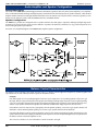
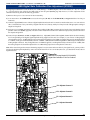
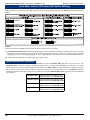
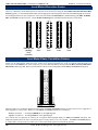
This DIP switch sets the Line Level Calibration, Reference Level, and PPM/VU Display Mode. See the descriptions
and diagram below for setting information.
Line Level (Auto) Calibration:
The unit is calibrated at the factory. To recalibrate:
1) Turn on the power.
2) Apply the desired reference level (nominal 0) signal to all channels.
3) Make sure the Reference Level DIP sections (2 and 3) are set to the nearest level of the input signal being applied
for calibration (i.e., 0, +4, +6 or +8). The user should make sure that the signal applied to all four channels is within
+/- 4 dB of the reference level selected by DIP switch sections 2 and 3.
4) Place DIP section 1 in the DOWN position.
5) Wait 10 seconds. The unit will remove the previous calibration and the new calibration will be applied.
6) Place DIP section 1 in the UP position and return unit to service.
7) Only ONE auto-calibration attempt may be made for each cycling of AC power to the unit. Once the Line Level
Calibration DIP switch has been placed in the CAL position, it is necessary to cycle the power before that DIP
switch will be functional again, EVEN if a calibration attempt was unsuccessful.
If one wishes to calibrate again, turn off the power to the unit and repeat steps 1 through 6.
Reference Level:
DIP switch sections 2 and 3 determine the Reference Level, which adjusts the level of the input signal and the
resultant level displayed on the LED bargraphs. Factory setting is +4 dB. See DIP switch diagram below for settings.
Bargraph Display Mode:
DIP switch sections 4 and 5 determine how peak levels are displayed for the associated meters on the front panel.
There are four possible settings; VU Only, VU-PPM Floating Segment, PPM Only, and PPM-PPM Floating
Segment.
The VU Only selection has a VU floating segment when a Peak Hold value is selected using the Internal 10-Position
DIP Switch Module (see page 24). The factory default setting is VU-PPM Floating Segment. See diagam below for
settings.
AMP Series Level Meter Rear Panel DIP Switch Settings
Meter Calibration
1
Display Mode
Reference Level
23
x
x
Calibrate
Operate
123456
45x
+8 dB
VU Only
+6 dB
VU-PPM Floating Segment
+4 dB
PPM Only
PPM-PPM Floating Segment
0 dB
123456
123456
Note: Position-6 of DIP switch is NOT used.
See AMP Series Level Meter Internal 10-Position DIP Switch Settings on page 24 for setting the Peak Hold and PPM
Ballistics characteristics.
Meter Calibration NOTE:
For more accurate indication of signal levels, meters are tuned to effect a “rounding” function, which occurs
BETWEEN the thresholds of any two bargraph segments. This means the level meter zero LED segment will turn
on at one-half the smallest spacing between LED segments (mid-scale resolution) before that segment's scale
indication. Below are the offset amounts.
53-Segment Meters: The “rounding offset” is 0.5 dB for the Analog (extended VU), Digital, Nordic, and
DIN scales. It is 0.25 dB for the BBC scale and 0.125 dB for the VU scale.
Example: Using the Analog (extended VU) scale, a meter calibrated for a +4 dBu nominal level will actually
turn the zero LED segment of the level meter on at +3.5 dBu (and so all segments will turn on at 0.5 dBu before
each ones associated silk-screened scale indication).
© 2004 Wohler Technologies Inc. ALL rights reserved
23