1
OWNER’S
MANUAL
Robert H. Peterson Co.
RHP
Models
G46-18/20-01(P)
G46-18/20-11(P)
G46-18/20-15(P)
G46-18/20(P)
C.S.A. CERTIFIED
GLOWING EMBERS
GAS FIREPLACE
LOG SET
G46-24-01(P)
G46-24-11(P)
G46-24-15(P)
G46-24(P)
G46-30-01(P)
G46-30-11(P)
G46-30-15(P)
G46-30(P)
G46 SERIES BURNER
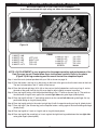
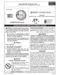
WARNING: If the information in this
manual is not followed exactly, a fire or
explosion may result causing property
damage, personal injury or loss of life.
- Do not store or use gasoline or other
flammable vapors and liquids in the
vicinity of this or any other appliance.
- WHAT TO DO IF YOU SMELL GAS.
• Open a window.
• Do not try to light any appliance.
• Do not touch any electrical switch; do not
use any phone in your building.
• Immediately call your gas supplier from
neighbor's phone. Follow the gas
supplier's instructions.
• If you cannot reach your gas supplier,
call the fire department.
Installation and service must be
performed by an NFI Certified or other
qualified, professional installer, service
agency or the gas supplier.
IMPORTANT: READ THESE INSTRUCTIONS
CAREFULLY BEFORE STARTING
INSTALLATION OF YOUR LOG SET
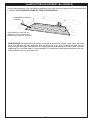
Your Peterson Real-Fyre Gas Log Set is to be installed
only in a solid-fuel burning fireplace with a working flue
constructed of noncombustible material. Solid fuels
shall not be burned in a fireplace where this gas log
set is installed. The installation, including provisions
for combustion, ventilation air and required minimum
permanent vent opening, must conform with the National
Fuel Gas Code (ANSI Z21.60a-2003 and CSA 2.26a2001) and applicable local building codes. In Canada,
the installation must conform with the current CAN/
CGA B149.1, and B149.2 Installation Code.Z223.1)
and applicable local building codes. A damper clamp
is included to maintain the minimum permanent vent
opening and to prevent full closure of the damper
blade. The chimney damper MUST be fully open
when burning the log set. Your log set is designed
to burn with yellow flames; adequate ventilation
is absolutely necessary.
IMPORTANT: To comply with certification, listings,
and building codes, and for safe operation and
proper performance, ONLY Peterson parts and
accessories MUST be used with this gas log set.
INSTALLER & CONSUMER :
These Instructions MUST be
retained with this appliance
ROBERT H. PETERSON CO. 14724 East Proctor Ave., City of Industry, CA 91746
REV 2 0603020800
1
No.L-A2-21506
Robert H. Peterson Co.
RHP
Models
G46-18/20-01(P) G46-30-01(P)
G46-18/20-11(P) G46-30-11(P)
G46-18/20-15(P) G46-30-15(P)
G46-18/20(P)
G46-30(P)
MANUEL
OWNERS
C.S.A. ENSEMBLE DE
LA GROSSE BÛCHE
DE LA CHEMINÉE
DU GAZ DES
CENDRES ARDENTES
ENTHOUSIASTE
CERTIFIÉ
G46-24-01(P)
G46-24-11(P)
G46-24-15(P)
G46-24(P)
G46 SÉRIE BRÛLEUR
INSTALLATION ET DIRECTIVES du FONCTIONNEMENT
IMPORTANT:
AVERTISSEMENT:
Si les informations dans
ce manuel ne sont pas suivies exactement, un feu
ou explosion peut résulter cause propriété endommage, blessure personnelle ou perte de vie.
Ne mettez pas en réserve ou utilisez de
l'essence ou autre vapeurs inflammables et
liquides dans le voisinage de celui-ci ou tout
autre appareil.
CE QUI Faire Si VOUS avez SENTI le GAZ
• n'essaie pas d'allumer de l'appareil.
• ne touche pas de changement électrique;
ne utilisez pas du téléphone dans votre bâtiment.
• appelle Immédiatement votre fournisseur du
gaz du téléphone d'un voisin et suit les directives des fournisseur du gaz.
• Si vous ne pouvez pas atteindre votre
fournisseur du gaz, appelle le département du
feu.
L’installation et service doivent être exécutés par un NFI Certified ou autre installateur
qualifié, professionnel, agence du service ou
le fournisseur du gaz.
LISEZ des DIRECTIVES de l'INSTALLATION AVEC
SOIN AVANT de COMMENCER INSTALLATION
D'ENSEMBLE de la GROSSE BUCHE
Votre Real-Fyre de Peterson Tronçonne l'Ensemble est
est installé seul dans un solide-combustible cheminée
brûlante avec un [flue] qui travaille a construit de matière
du non-combustible. Combustibles solides ne seront
pas brûlaient dans une cheminée où un gaz tronçonne
l'ensemble est installé. Le minimum permanent décharge
l'ouverture a fourni par la cheminée de la cheminée ou
cheminée plus humide décharger les produits du [flue]
est inscrit sur page 2. Une douche froide de cheminée
doit être arrangé maintenir dans une manière le minimum
permanent décharge l'ouverture. L'installation, y compris
vivres pour combustion et ventilation aère, doit conformer
avec le National américain le Code du Gaz de la Combustible Standard (ANSI Z21.60a-2003 et CSA 2.26a-2001)
et codes du bâtiment applicables locaux. Au Canada
l'installation doit être conforme avec le courant PEUT/
CGA B149.1 et B149.2 code de l'installation. La douche
froide de cheminée doit être complètement ouverte
quand brûler l'ensemble de la grosse bûche. Votre
ensemble de la grosse bûche est conçu pour brûler
avec les flammes du jaune; la ventilation adéquate
est absolument nécessaire.
IMPORTANT: Pour opération sûre et performance
adéquate et pour se conformer avec Certification
CSA, SEULEMENT Peterson part et les accessoires
doivent être utilisés avec cet ensemble de la grosse
bûche du gaz
INSTALLATEUR & CONSOMMATEUR: Ces
directives doivent être retenues avec cet appareil.
2
G46 GAS LOG SET
TABLE OF CONTENTS
PAGE #
1-2
TOPIC
Cover - Important Safety Warnings
Table of Contents
3
Burner - Parts Lists:
General Burner and Log Parts List
G46 Manual Valve System
G46-11 Remote Valve System
G46-01 Electronic Valve System
G46-15V Remote Valve (Variable flame) System
4
5
5
6
6
Important Information:
General information
Technical Data Table
Minimum Damper Opening Data
7
Installing your gas log set:
Damper clamp Installation
Installation of the burner
Special Instructions for G46-01 Installation 10
Securing the burner
Granule and ember placement
Log Placement
Optional Log Placement (Charred series and Campfyre)
11
11
12-13
14-15
Lighting Instructions:
G46 Manual valve
G46-11 Remote valve
G46-01 Electronic valve
G46-15 Remote Variable flame valve
16-17
18-19
20-21
22-23
8
8-9
Operating Information:
Pilot Burner Adjustment
Flame pattern adjustment
24
25
Maintenance
25
Warranty
26
3
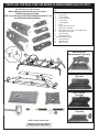
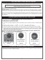
PARTS LIST FOR REAL-FYRE G46 SERIES GLOWING EMBER GAS LOG SETS
Log styles, sizes and parts will vary depending upon
the G46 Series model ordered.
When ordering replacement parts, be sure to
indicate your log set model.
NOTE: Only the logs for the WO-24 Woodland Oak 24" Set
are illustrated and listed below.
Description
1.
2.
3.
4.
5.
6.
20" rear log
24" front log
15" top left log
15" top right log
9" top left log
9" top right log
7.
8.
9.
10.
11.
12.
13.
Grate
Log locators with screws
Burner pan assembly
G46 safety control system (see Pages 5-6)
Piezo ignitor assembly
Pilot assembly
Sand (natural gas)
or Vermiculite (L.P. gas)
14.
Glowing embers
15.
Damper clamp
16.
Connector kit
5
1
Item
No.
6
2
3
4
G46 Burner with
Manual Control (Top view)
8
7
G46-11 Burner
(Top view)
12
11
9
10
PILOT
ON
OFF
G46-15 Burner
(Top view)
13
14
16
15
NOTE: Photos not to scale
Actual parts may differ.
4
G46-01 Electronic Burner
(Top view)
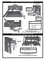
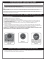
SAFETY CONTROL SYSTEM FOR G46 MANUAL
PILOT ASSEMBLY
(Rear view)
CERAMIC
ELECTRODE
(ITEM 21)
LOCATION OF
ORIFICE
19
PILOT
ASSEMBLY
(ITEM 20)
Item
No.
17.
18.
20
19.
20.
21.
22.
22
17
Description
Safety control valve
Pressure regulator (natural gas)
Pressure regulator (L.P. gas)
Handle assembly
Pilot assembly
Ceramic electrode
Adapter elbow
G46 Burner showing valve layout
under heat shield (rear view).
18
NOTE: DO NOT REMOVE HEAT SHIELD
SAFETY CONTROL SYSTEM FOR G46-11(P)
23
Item No.
Description
24
23.
24.
Safety control valve
Brass elbow 1/2" flare x 3/8"MIP
G46 Burner showing valve layout
under heat shield.
NOTE: DO NOT REMOVE HEAT SHIELD
5
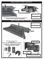
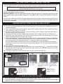
SAFETY CONTROL SYSTEM FOR G46-01(P)
26
25
Item
No.
G46 Burner showing Remote Control layout under heat shield.
Description
25.
26.
Safety control valve
Pilot assembly
NOTE: DO NOT REMOVE HEAT SHIELD
SAFETY CONTROL SYSTEM FOR G46-15(P)
Item
No.
28
27.
28.
Description
Safety control valve
Pilot assembly
27
G46 Burner showing 15 valve
under heat shield.
FLAME HEIGHT
CONTROL KNOB
NOTE: DO NOT REMOVE HEAT SHIELD
SUPPLIED VR-1 REMOTE WITH RECEIVER,
HEATSHIELD, BATTERIES & WIRING
ON/OFF IGN/PILOT
KNOB
CONNECTION TERMINALS FOR
VR-1 WIRING TO RECIEVER
6
G46 SERIES IMPORTANT INFORMATION
Do not use this log set if any part has been under
water. Immediately call a qualified professional
service technician to inspect the appliance and to
replace any part of the control system and any gas
control which has been under water.
A fireplace screen must be in place when the log
set is burning. Provisions for adequate combustion
air must be maintained. Combustion air is adequate
when all flames curl into the fireplace and away from
the screen.
The appliance and its individual shutoff valve must
be disconnected from the gas supply piping system
when testing the system at test pressures in excess
of ½ psig. This is accomplished by closing the gas
supply line valve, which is required by NFPA54,
section 5.54.
When glass fireplace doors are used, operate the
gas log set with the doors open.
Keep the area of the gas log set clear and free from
combustible materials, gasoline and other flammable vapors and liquids.
THIS GAS LOG SET CONFORMS TO THE
ANSI Z21.60a -2003 STANDARD.
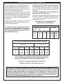
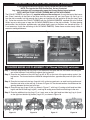
The minimum size fireplace in which the log set is to be
installed is listed in the "Technical Data Table" below.
The minimum chimney height from the hearth to the
top of the chimney is 15'.
Real-Fyre G46 Series Technical Data Table
The minimum inlet gas supply pressure for the
purpose of input adjustment is 5" for natural
gas and 11" for propane gas. The maximum inlet
gas supply pressure for this burner is 14" for
natural and propane gas.
Minimum Fire Box Dimensions
Front
Size
Opening
Depth
Height
Nat.
Propane
18"
20"
24"
30"
24"
26"
30"
36"
13"
13"
13"
13"
16"
16"
16"
16"
40,000
40,000
55,000
65,000
40,000
40,000
55,000
65,000
Minimum Free Opening Area of Chimney Damper for Venting
For Factory Built Fireplaces
Log Set Sizes
Chimney
Height
18"&20"
15'
20'
25'
30'
15 SQ"
14 SQ"
12 SQ"
10 SQ"
24"
21 SQ"
18 SQ"
16 SQ"
15 SQ"
BTU Rating
Log Set
*
For Masonry Built Fireplaces
Log Set Sizes
30"
29 SQ"
24 SQ"
21 SQ"
19 SQ"
18"&20"
23 SQ"
21 SQ"
20 SQ"
19 SQ"
24"
31 SQ"
28 SQ"
27 SQ"
26 SQ"
30"
40 SQ"
36 SQ"
34 SQ"
33 SQ"
*Note: A damper stop clamp is provided as a means to prevent full
closure of the damper blade. Fully open the damper when burning
the log set (see page 8 for details on the damper clamp).
Your log set is designed to burn with yellow flames;
Adequate ventilation is absolutely necessary.
IMPORTANT: To comply with certification, listings and building code acceptances and for
safe operation and proper performance ONLY Real-Fyre parts and accessories may be
used with this gas log set. Real-Fyre valves, controls, parts and accessories have been
designed, tested and certified for use with Real-Fyre Gas Log Sets. Use of other controls,
parts and accessories which are not designed for use with Real-Fyre Gas Log Sets is
prohibited and will void all warranties, certifications, listings and building code approvals,
and may cause property damage, personal injury or loss of life.
7
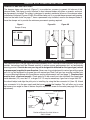
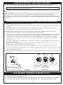
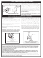
DAMPER STOP CLAMP INSTRUCTIONS
DAMPER CLAMP INSTRUCTIONS
The damper clamp with hex bolt (Figure 1) is provided as a means to prevent full closure of the
damper blade. The clamp is easily attached to most damper blades with pliers or wrench, and must
be permanently installed. The clamp is designed to prevent accidental closure of the damper when
installed as illustrated (Figures 2 A&B). Should the clamp not fit, or provide the permanent vent opening
listed on the table found on page 7, have a permanent stop installed, remove the damper blade or
have the damper cut to provide the minimum permanent opening required.
Figure 1
Figure 2A
Figure 2B
Damper Clamp
SET SCREW
Open
Closed
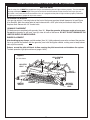
INSTALLING YOUR REAL-FYRE GAS LOG SET
Your Peterson Real-Fyre gas log set must be installed by an NFI Certified or other qualified, professional
installer. Instructions must be followed carefully to ensure proper performance and an aesthetically
pleasing product. Check to be sure your log set is designed and labeled for the type of gas (natural
or propane gas) supplied to your fireplace. Never use a log set designed for natural gas with propane
gas or a log set designed for propane gas with natural gas. Real-Fyre gas logs must be installed only
in a wood-burning fireplace with the minimum venting requirements met (see page 7). Fireplace floor
must be level, clean and smooth. Check parts list to be sure all parts are included. Gas supply pipe
inside diameter (I.D.) must be 1/2" or larger. 3/4" I.D. may be necessary if gas line is longer than 20'.
You should adjust and align the pilot prior to installing by using the flex connector kit (Item 16). Attach
your connector kit to the gas supply and the burner outside the fireplace. This will allow you to move
the burner at an angle in order to access the pilot adjustment screw on the valve (see page 24 for pilot
adjustment).
LARGE ADAPTER
Figure 3
CONNECTOR KIT
GAS
SUPPLY
BURNER
VALVE
GAS INLET
ELBOW
Postion of Burner Gas Inlet Valve on
G46-11 Model
8
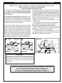
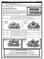
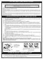
INSTALLING YOUR REAL-FYRE GAS LOG SET (Continued)
NOTE: REFER TO PARTS LIST (PAGE 4) WHEN FOLLOWING THESE INSTRUCTIONS.
INSTALLATION OF LOG SET IN YOUR FIREPLACE
(be sure the gas to the fireplace is off)
1. The burner gas inlet is located in front of the gas 3. Position the burner in the center rear of the fireplace.
valve (Figure 3). Use teflon tape or pipe compound Connect the connector kit tubing (Item 16) to your gas
on all pipe thread male connections, except where supply. Be sure that the burner assembly and the valve
brass to brass.
remain in alignment. If the valve shifts position during
installation, the burner assembly may not sit flat in the
FORTHE G46 AUTOMATIC MILLIVOLT VALVE Attach
fireplace, causing improper gas flow. It may also cause
the connector kit 3/8" adaptor to the brass elbow (Item interference with the control knob operation.
No. 24) on the valve. The log set user should make
• Make sure that the safety control system is in the
themselves familiar with the valve control layout before "OFF" position.
installing the burner into the fireplace.
• Turn on the gas to the fireplace and check for leaks
at all connections by using a soapy water solution.
2. Next clamp the log locators onto the grate fingers
Never use an open flame to check for leaks.
(one in from either end). The log locators will fit on either • Light the pilot (pages 16-23) and check for proper
side of the grate finger (see Figure 4a and b). Align the adjustment. If the pilot needs to be adjusted, follow the
locator screw so that it projects down into the locator instructions on page 24. Turn the pilot off.
holes on the burner. Attach nuts to screws and finger
• Position the grate on the burner (Figure 4c). Push the
tighten only. Place the bottom log on the grate (see Figure burner-grate assembly as far as possible to the rear of
4c) and align the log against the locator. Fully tighten
the fireplace, then remove the grate.
the screws and then remove the logs and grate until
completing gas connection and granule placement.
A
Grate
Log locator
Figure 4C
B
HEAT
CHAMBER
LOG
LOCATORS
FRONT
BOTTOM
LOG
REAR
BOTTOM
LOG
GRATE
BURNER
Figure 4A
Burner
LOG
LOCATOR
SCREW
Figure 4B
IMPORTANT:
Log locators may be installed in either configuration (A or B),
depending on burner size. Adjust as necessary to ensure screws
fit in locator holes in burner. This secures the burner and grate
from movement, and keeps the logs in place for optimum log
set operation.
NOTE: IF YOUR LOG SET IS A G46-01(P) MODEL CONTINUE
FOLLOWING THE INSTRUCTIONS ON PAGE 10.
FOR ALL OTHER MODELS PROCEED TO PAGE 11.
9
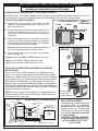
INSTALLING YOUR REAL-FYRE GAS LOG SET (Continued)
SPECIAL INSTRUCTIONS FOR G46-01-xx(P) MODELS
Installing pine cone with switch for 01M models
CONNECTING THE IGNITION PACK TO THE G46-01(P) VALVE
The G46-01-xx(P) valve comes complete with the wiring harness connected to the pine cone switch. You may
wish to ensure it is correctly connected before finally connecting the 3 wires to the valve as below.
TO CHECK THE WIRING ASSEMBLY:
Figure 5
CHECK CONNECTIONS
A. Check that the wiring harness is fitted tightly into the
STEP 5 (A-B)
connector on the green ignitor pack in the rear of the
S WIRE
I WIRE
pine cone (Figure 5A).
B. Check that the female connectors on the two black wires
from the pilot assembly (wires marked "I" and "S") are
inserted fully into the male connectors on the ignitor pack
(Figure 5B).
C. Check the connection of the red and black wires of the
wire harness to the respective counterpart wires from the
battery holder (red-red and black-black). The two brown
wires should be connected to the switch.
Note: the 2 spare brown wires with coated male connectors
are used to connect an optional remote system.
D. Finally connect the wires to the valve in the following
order (see Figure 6):
Orange wire marked THTP - to THTP connector on valve
A
B
WIRE HARNESS
CONNECTOR
IGNITOR PACK
Figure 6
STEP 5(D)
D
Black wire marked TP - to TP connector on valve
Green wire marked TH - to TH connector on valve
ORANGE
WIRE
MARKED
THTP
GREEN
WIRE
MARKED
TH
INSTALLING OR REPLACING BATTERIES FOR IGNITION
BLACK
WIRE
MODULE PACK
MARKED
Two 1.5-volt (D-cell) alkaline batteries are supplied with your
TP
log set. To install or replace batteries, remove the green ignition
module pack, held in place with a velcro strip, from rear of the pine Figure 7
Pine cone
cone receiver (Figure 7). Remove battery holder and old batteries
cover
from the pine cone. Replace (or install) batteries into the battery
with switch
holder, making sure they are installed according to the diagram in
Velcro
battery holder. Replace holder, pressing it firmly against the velcro
strips
strip. Replace ignition pack and press firmly into place. The ignition
system is now ready to operate.
Battery holder
NOTE: For your system to work properly, it is suggested that you
with batteries
replace batteries annually with fresh batteries. Always replace all
Ignition Module Pack
the batteries at the same time.
SWITCH
Wiring Diagram for 01 remote switch
PINE CONE
(BROWN)
2 WIRES
TO SWITCH
TO PILOT ASSEMBLY
PROBES
I
IGNITOR PACK
S
I
S
ORANGE (THTP)
WIRE HARNESS
(RED) TO
BATTERY
HOLDER
VALVE MAGNET
WIRE (BLACK)
(DO NOT REMOVE)
G46
Electronic
Valve
GREEN (TH)
(BLACK) TO
BATTERY
HOLDER
BLACK (TP)
(Drawings not to scale.)
10
PINE CONE PLACEMENT
The designer pine cone incorporating
the control switch is aesthetically
designed and is an integral part of the
operation of your set. The pine cone
can be placed as close to the valve
as you desire, but never closer than
4" from the flame.
CAUTION: THE PINE CONE MAY
BE HOT DURING AND DIRECTLY
AFTER OPERATION OF YOUR
GAS LOG SET.
INSTALLING YOUR REAL-FYRE GAS LOG SET (Continued)
IMPORTANT
For all valves, the air MUST be purged from the gas line before the pilot will light and burn properly. The time needed
to purge will depend on the length of the gas line to the unit and the amount of time since the unit or gas line was
last used. It may take several minutes before all the air is purged and the pilot will light and burn properly. Follow the
"Lighting Instructions" (pages 16-23) in this manual.
SECURING THE BURNER
Your gas log set has 2 securing holes at the front of the burner pan heat shield (see parts list and Figure
8 for location). Mark the center point of each hole and drill a 3/16" pilot hole (one for each side) into the
fireplace floor. Secure with 1/4" anchor bolts.
GRANULE PLACEMENT
Fill the burner pan completely with granules (Item 13). Slope the granules at the same angle as burner pan.
Do not allow granules to spill over front lip, sides or back of the burner. DO NOT PLACE GRANULES ON
IGNITOR SHIELD OR KNOB SHIELD.
EMBER PLACEMENT
After breaking up any clumps, sprinkle embers (Item 14), lightly and evenly over entire surface of the granules.
You may sprinkle the embers (not the granules) over knob and ignitor shields, making sure to keep embers
clear of pilot assembly.
Embers around the pilot will block air flow, causing the pilot to overheat and shutdown the system.
To check operation, light pilot and burner (pages 16-23).
Figure 8
LOG LOCATOR
BOLTS
24" unit shown.
LOCATOR
HOLE
PERFORA
TE
AREA D
EMBERS
ONLY
IGNITOR
SHIELD
EMBERS
PILOT
ASSEMBLY
BURNER
SECURING
HOLE
11
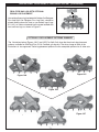
INSTALLING YOUR REAL-FYRE GAS LOG SET (Continued)
Note: For Charred Series see Page 14
For Western Campfyre Series see Page 15.
Proper log placement is important to insure proper performance of your Real-Fyre gas log set. Be sure to follow
the log placement instructions carefully. 3 optional log placement patterns, an exclusive feature of Real-Fyre
gas logs, are explained below.
Figure 9
REAL-FYRE GAS LOG SETS 18"-30".
1
24" Woodland Oak (WO) log set shown.
For all Options - Step 1. Place the rear bottom log (Log #1) on the
back of the grate (Figure 9), and slide it forward against the log locators.
2
Place the front log (Log # 2) on the front of the grate and slide it back
against the log locators. The log locators ensure that adequate space
between the logs is maintained for a cleaner burn.
Option 1 - Step 2.
Option 1 - Step 3.
Figure 10A
Option 1
Step 2.
Place the the middle log (Log #4) to rest on the front and rear bottom logs as shown
in Figure 10A. Place Log #3 so it rest on Log #4 and the front log, as shown in figure
10A. Ensure they are placed across the space between the logs.
Place the top logs (Logs #5 & 6) as shown in Figure 10B, with Log # 5 resting on Log
#3 and the front log, and Log #6 resting on the rear log and Log #4.
4
Figure 10B
Option 1
Step 3.
3
5
6
Option 2 - Step 2.
Option 2 - Step 3.
Option 3 - Step 2.
Option 3 - Step 3.
Figure 10C
Option 2
Steps 2 & 3.
Place the middle logs parallel as shown in Figure 10A. Log #3 is placed with one end
on the front log, the other end resting on Log #4.
Place Log #5 resting on the front log and the left middle log, and Log #6 resting on the
rear log and the right middle log as in Figure 10C.
Place the middle logs (Logs #3 & 4) so they are parallel, resting on the front and rear
logs across the space as shown in Figure 10D.
Place top logs #5 & 6 so they are parallel and rest across Logs #3 & 4, as in Figure
10D.
Figure 10D
Option 3
Steps 2 & 3.
6
5
5
4
4
3
6
3
CAUTION: BURN HAZARD.
LOGS WILL REMAIN HOT FOR SOME TIME AFTER USE.
YOU MUST MAINTAIN THE LOG LAYOUT AS SHOWN TO ENSURE PROPER
OPERATION OF YOUR LOG SET.
IF YOU NEED TO REPOSITION ANY LOG TO MAINTAIN THE PROPER LAYOUT,
USE HEAT RESISTANT GLOVES OR ALLOW LOGS ADEQUATE TIME TO COOL BEFORE HANDLING.
12
INSTALLING YOUR REAL-FYRE GAS LOG SET (Continued)
Figure 11
REAL-FYRE GAS LOG SETS OPTIONAL
BONUS LOG PLACEMENT
Your optional bonus log (included with Golden Oak Designer
Plus and Split Oak Designer Plus Log Sets) should be
placed directly above the front or rear bottom logs (Logs
#1 & #2), so it does not extend into the space between the
front and rear logs, as shown in Figure 11.
Log #7
OPTIONAL LOG PLACEMENT PATTERNS SUMMARY
The illustrations below (Figures 12A-C and 12D-F for Split Oak) show the three basic log placement
patterns available for G46 Real-Fyre C.S.A. Certified gas log sets. The mirror image of each of the
illustrations is also approved. These log placement patterns are the acceptable patterns for all other sets.
Figure 12C
Figure 12A
Figure 12B
Figure 12F
Figure 12D
Figure 12E
13
INSTALLING YOUR REAL-FYRE GAS LOG SET (Continued)
If you have purchased this style of log set, follow the instructions below.
NOTE: The logs for the CHD Charred Oak Set are illustrated.
Log styles and sizes will vary depending upon the Charred Series log set ordered.
NOTE: INSTRUCTIONS ON THE FYREBED MAY NOT BE APPLICABLE
The COALS FYREBED (see Figure 13) supplied with your Charred log set, fits onto the back of the burner
pan. Place it centrally on the back so the outer front tabs hang over the pan (see Figure 14). Set it so it is
over the pilot assembly, but high enough that it does not interfere with the operation of the pilot (see Figure
13). Cover the surface of the COALS FYREBED with the GLOWING EMBERS, supplied with your Charred
Series log set, making sure to keep the GLOWING EMBERS clear of the pilot assembly. For best glowing
performance, they should be applied evenly and pulled slightly apart so the fibers are somewhat loose. (It
is not necessary to pile the entire bag of the GLOWING EMBERS). Center flame must be clearly visible, or
excessive sooting could occur.
Figure 13
Figure 14
CHARRED SERIES LOG PLACEMENT - 24" Charred Oak (CHD) set shown
Step 1. Place the long bottom rear log (Log #1) on the back of the grate with the flat hollow side facing the
rear of the fireplace. Push the log up against the log locators.
Step 2. Place the two sections of the front log (Log #2L & 2R) on the front of the grate and up against the
log locators. The charred sections should be facing each other, approximately one inch apart at the
top.
Step 3. Place the two top knot hole logs (Logs #3 & #4) so that one end rests on each front log section and
the other end rests on the rear log, as shown in Figure 16. The charred sections should be over the
opening between the front and rear logs.
Step 4. Place the top logs (Logs #5 & 6) as shown in Figure 17, with Log # 5 resting on left hand knot hole
log #3 and the left front log (Log #2L), and Log #6 resting across both knot hole logs to the rear.
Step 5. Place the additional top log (Log #7) so it rests near on the right hand knot hole log (Log # 4) and
on the right front bottom log section (Log # 2R ) as shown in Figure 18.
6
1
3
4
5
2L
Figure 15
7
2R
Figure 16
Figure 17
14
Figure 18
INSTALLING YOUR REAL-FYRE GAS LOG SET (Continued)
WESTERN CAMPFYRE STYLE LOGS LAYOUT SUMMARY
If you have purchased this style of log set, follow the instructions below.
1
6
2
5
4
8
3
7
9
Figure 19
WESTERN CAMPFYRE 24
1. MWCFL-18BR
2. MWCFL-18L
3. MWCFL-18R
4. MWCFL-13T
5. MWCFL-13TY
REAR LOG
LEFT LOG
RIGHT LOG
TOP LOG
TOP LOG
ITEMS
6. MWCFL-10TY
7. MWCFL-8T1
8. MWCFL-11T
9. MWCFL-5T
SCREEN
TOP LOG
TOP LOG
TOP LOG
TOP LOG
200394
NOTE: LOG PLACEMENT is very important for the proper operation and performance of the
Real-Fyre gas log set. Please follow these instructions carefully. Refer to the photo
(Figure 19) for log numbering and the overall look of the completed layout.
Step 1. Install the coals fyrebed provided with your G46 as shown on page 14.
Step 2. Place the bottom rear log (#1 in the photo) on the back of the grate so that the bark faces to the front.
The two flat indentations and “V” notch will be face up.
Step 3. Place the left and right logs (#2 & #3) so they rest on the flat indentations on the rear Log #1 and on
the ends of the grate front bar leg. You may need to adjust slightly to secure in position.
Step 4. Place top log #4 resting with the pointed end fitting in the “V” notch on the rear log #1. The notch on
the other end of Log #4 rests against the second right side outer grate finger (check photo).
Step 5. Place top log #5 with the “Y” end resting securely on the second left side outer grate finger, the opposite end resting on Log #4 (check photo).
Step 6. Place top log #6 resting in the cutout on right log #3 with its opposite resting on Log #4 (check photo).
Step 7. Place top log #7 (the shortest log) on the fireplace bottom, resting against the front middle grate finger
(check photo)
Step 8. Place top log #8 so it rests on Log #4 and on Log #3 (check photo).
Step 9. Place top log #9 (the round log) so it rests against the right front leg and between the two right side
outer grate fingers (check photo).
15
FOR YOUR SAFETY, READ BEFORE LIGHTING
* We recommend that before you install your log set you familiarize yourself with the control valve layout. This will help
you to be confident operating the log set when fully installed (see Figures on page 16-23 for typical control positions).
WARNING: If you do not follow these instructions exactly, a fire or explosion may result causing
property damage, personal injury or loss of life.
The Real-Fyre G46 Series gas log set has a pilot which can be lit by hand using the piezo ignitor. When lighting
the pilot, follow these instructions exactly.
BEFORE LIGHTING, smell all around the gas log set area for gas. Be sure to smell next to the floor as some gas is
heavier than air and will settle on the floor. IF YOU SMELL GAS, FOLLOW THE INSTRUCTIONS ON PAGE 1.
Use only your hand to push in or turn the gas control knob. Never use tools. If the knob will not push in or turn by
hand, don't try to repair it. Call a qualified, professional service technician. Force or attempted repair may result
in fire or explosion.
LIGHTING INSTRUCTIONS FOR G46 MANUAL GAS LOG SETS
1. STOP Read the safety information on this page.
2. Turn "OFF" any electrical appliance (such as the Peterson warm air circulator) if used with the log set.
to "OFF" (Figure 20).
3. Push in the gas control handle slightly and turn clockwise
NOTE: The handle cannot be turned from "PILOT" to "OFF" unless the handle is pushed in slightly. Do not
force.
Wait five minutes to clear out any gas. If you then smell gas, STOP! Notify your gas supplier or the fire department
immediately. If you don’t smell gas, go on to step 4.
to "PILOT" (Figure 20). Push the control handle all the way
4. Turn the gas control handle counterclockwise
in and hold it. Press the igniter button one or more times to light the pilot. Continue to hold the control handle
for approximately one minute after the pilot is lit. When you release the handle, it will pop out and the pilot
should remain lit.
• If the handle does not pop out when released, stop and immediately call your service technician or gas
supplier.
• If the pilot will not light, repeat steps 3 - 4 and light the pilot manually.
• If the pilot will not stay lit after several tries, turn the gas control handle to "OFF" and call your service technician
or gas supplier.
5. If an electrical appliance is used with the log set, turn on or reconnect that appliance.
6. Turn the gas control handle counterclockwise
to "ON" (Figure 20) to ignite the burner.
NOTE: Periodically check the pilot flame (Figure 26, page 24) for proper flame pattern.
MAKE SURE THE THERMOCOUPLE AND PILOT ASSEMBLY ARE IN CORRECT ALIGNMENT WITH EACH
OTHER. (SEE FIGURE 26, PAGE 24).
ON
1. LIGHTING - turn knob to "OFF"
and wait 5 minutes before lighting.
Figure 20
1. Use "OFF"
only 2. Turn Dial to "PILOT"
position.With match
when complete shutdown
ready press knob in and
is necessary.
hold for 60 seconds while
lighting pilot.
ON
ON
PILOT
OFF
PILOT
ON
PILOT
OFF
PILOT
OFF
OFF
3. Turn knob to "ON"
to light burner.
TO TURN OFF THE MANUAL GAS LOG SET
1. From the "ON" position, turn the control knob clockwise
to the "PILOT" position. The log set will extinguish
and the pilot will remain lit.
2. If complete shutdown is desired, from the "PILOT" position, push in the control knob slightly and turn clockwise
to the "OFF" position. Do not force the knob.
16
POUR VOTRE SECURITE, LISEZ AVANT D’ALLUMER
* Nous recommandons qu’avant que vous installiez votre grosse bûche mise vous vous familiarisez avec la disposition de la valve du contrôle. Cela vous aidera
pour être opérer plus confiant la grosse bûche mise quand a complètement installé (voyez des Illustrations dessous pour contriol typique placez).
PRÉVENIR: Si vous ne suivez pas ces instrucions exactement, un feu ou explosion peuvent résulter, en causant dégât de la propriété, blessure personnelle ou perte de vie.
Le l’ensemble de la grosse bûche du gaz a un pilote qui doit être allumé à la main. Quand allumer le pilote, suivez ces directives exactement
AVANT d’ALLUMER, sentez autour de la grosse bûche du gaz mis la région pour le gaz. Soyez sûr de sentir à côté du sol parce qu’un
peu de gaz est plus lourd qu’air et résoudra par terre. SI VOUS SENTEZ DU GAZ, SUIVEZ LES DIRECTIVES SUR PAGE 1.
N’utilisez pas la grosse bûche du gaz mise si toute partie a été sous eau. Immédiatement appelez un qualifie, les prifessional entretiennent le technicien pour inspecter la grosse bûche du gaz mis et remplacer toute partie du système du contrôle et tout gaz contrôlent qui
a été sous eau.
allumant directives pour G46 ensemble de la grosse bûche du gaz manuel
1.
ARRETEZ! Lisez les renseignements de securite au-dessus.
2.
Arretez "FERMÉ" tout appareil electrique (tel le Circulateur d’Air Chaud de Peterson) sil est utilise en conjonction avec lensemble
de buches.
3.
Appuyez legerement sur la manette de commande du gaz et tournez-le dans le sens des aiguilles d’une montre jusqua la
positiond’arret 'fermé' sans qu’on appuie legerement dessus. Priere de ne pas la forcer.
Attendez cinq minutes afin de laisser se dissiper tout residu de gaz. Si vous alors du gaz, ARRETEZ! Appelez immediatement
fournisseur de gaz ou les pompiers. si vous ne sentez pas de gaz, procedez a l’operation 4.
4.
Tournez la manette de commande du gaz dans les sens contraire des aiguilles d’une montre jusqua la position veilleuse "PILOT"
(Illustr. 19F). Poussez la manette de commande jusqu’au fond et tenez-la. Appuyez sur le Bouton d’Allumage une ou plusieurs
fois afin d’allumer la veilleuse. Continuez a tenir la manette de commande pendant a peu pres une minute apres allumage de
la Veilleuse. Lorsque vous relachez la manette, celle-ci va ressortir et la veilleuse devrait rester allume. Si elle eteint, repetez
l'operation 3 & 4.
• Si la manette de commande ne ressort pas lorsque vous la relachez, arretez-vous et appelez immediatement votre technicien de
service ou fournisseur de gaz.
• Si la veilleuse ne rester pas allumee apres plusieurs tentatives, tournez la manette de commande du gaz a la position arret
"FERMÉ" et appelez votre technicien de service ou fournisseur de gaz.
5.
Si vous utilisez un appareil electique avec l’ensemble de buches, rebranchesz ou mettez cet appareil en position de marche.
6.
Tournez la manette de commande du gaz dans le sens contraire des aiguilles d’une montre jusqu’ a la position de marche “SUR”
(Illustr. 20F) afin d’allumer le bruleur.
NOTEZ: verifez de temps en temps la flamme de la veilleuse (illustr. 26, Page 24) afin de vous assurer que celle-ci maintient une forme
correcte.
ON
1. POUR ALLUMER - Tournez le robinet
jusqu’a la position d’arret “OFF”
et
attendez 5 minutes avant d’allumer.
1. Utilisez la position
d’arret “OFF”
seulment lorsqu’il est
necessaire d’eteindre
completement
l’appareil.
Figure 20F
ON
ON
PILOT
OFF
PILOT
ON
PILOT
OFF
PILOT
OFF
OFF
2. Tourner le cadran a
la position veilleuse
Avec
“PILOT”
une allumette prete,
appuyez sur le robinet
et tenez-le pendant
60 secondes tout en
allumant la veilluse.
3. Turn knob to "ON"
to light burner.
POUR ETEINDRE L’ENSEMBLE DE BUCHES AU GAZ
1. A partir de "SUR" position, tournez dans le sens des aiguilles du bouton de contrôle à la position "PILOTE". L'ensemble
du buches éteindra et le pilote restera allumé.
2. Si vous desirez eteindre completement l’appareil, appuyez legerement sur la manette de commande du gaz et tournezla dans le sens des aiguilles d’une montre jusqu’ a la position d’arret "OFF". Priere de ne pas forcer la manette.
17
FOR YOUR SAFETY, READ BEFORE LIGHTING
* We recommend that before you install your log set you familiarize yourself with the control valve layout. This will help
you to be confident operating the log set when fully installed (see Figures on pages 16-23 for typical control positions).
WARNING: If you do not follow these instructions exactly, a fire or explosion may result causing
property damage, personal injury or loss of life.
The Real-Fyre G46 Series gas log set has a pilot which can be lit by hand using the piezo ignitor. When lighting
the pilot, follow these instructions exactly.
BEFORE LIGHTING, smell all around the gas log set area for gas. Be sure to smell next to the floor as some
gas is heavier than air and will settle on the floor. IF YOU SMELL GAS, FOLLOW THE INSTRUCTIONS ON
PAGE 1.
Use only your hand to push in or turn the gas control knob. Never use tools. If the knob will not push in or turn
by hand, don't try to repair it. Call a qualified, professional service technician. Force or attempted repair may
result in fire or explosion.
LIGHTING INSTRUCTIONS FOR G46-11 REMOTE GAS LOG SET
1. STOP! Read the safety information above.
2. Turn "OFF" any electrical appliance (such as the Peterson warm air circulator or remote control system)
if used with the log set.
3. Place the "switch" or "remote" in "OFF" position.
4. Push in the control knob and turn clockwise
to the "OFF" position.
5. Wait five (5) minutes to clear out any gas. If you then smell gas, STOP! Follow the instructions on Page 1.
6. Find the pilot by following the metal tube from the gas control. Pilot is located at the right rear of the burner
pan.
7. Turn the gas control knob counterclockwise
to "PILOT" (Figure 21). Push the control knob all the way
in and hold it. Press the igniter button several times to light the pilot. Continue to hold the control knob
for approximately one minute after the pilot is lit. When you release the knob, it will pop out and the pilot
should remain lit.
• If the knob does not pop out when released, STOP! Immediately call your service technician or gas supplier.
• If the pilot will not light, repeat steps 4 - 7 and light the pilot manually.
• If the pilot will not stay lit after several tries, turn the gas control knob to "OFF" and call your service
technician or gas supplier.
8. Turn gas control knob counterclockwise
to "ON".
9. If an electrical appliance is used with the log set, turn on or reconnect that appliance.
10. To operate, flip the "toggle switch" to "ON" or put the remote handset in the "ON" position.The burner will
ignite.
NOTE: Periodically check the pilot flame for proper flame pattern (see Figure 28).
MAKE SURE THE THERMOPILE AND PILOT ASSEMBLY ARE IN CORRECT ALIGNMENT WITH EACH
OTHER (SEE FIGURE 28, PAGE 24).
OFF
ON
T
T
LO
PI
TOGGLE
SWITCH
Figure 21
PILOT
1. Use "OFF"
only when complete
shutdown is necessary.
OF
F
ON
1. LIGHTING - turn
knob to "OFF"
and wait 5 minutes
before lighting.
OFF
PILOT ADJUSTMENT
UNDER CONTROL
KNOB
ON
LO
PI
HEAT SHIELD
CONTROL
KNOB
PILOT
ON
OFF
2. Turn dial to ''PILOT" 3. Turn knob to "ON"
to light burner.
position. With
match ready press
knob in and hold for 60
seconds while lighting
pilot.
TO TURN OFF THE G46-11 REMOTE GAS LOG SET
1. Place the remote or switch in the "OFF" position. The pilot will remain lit.
2. If complete shutdown is desired, remove the radiant heat shield. Push in the control knob and turn clockwise
to the "OFF" position. Replace the radiant heat shield.
18
POUR VOTRE SECURITE, LISEZ AVANT D’ALLUMER
* Nous recommandons qu’avant que vous installiez votre grosse bûche mise vous vous familiarisez avec la disposition de la valve du contrôle. Cela vous aidera
pour être opérer plus confiant la grosse bûche mise quand a complètement installé (voyez des Illustrations dessous pour contriol typique placez).
PRÉVENIR: Si vous ne suivez pas ces instrucions exactement, un feu ou explosion peuvent résulter, en causant dégât de la propriété, blessure personnelle ou perte de vie.
Le l’ensemble de la grosse bûche du gaz a un pilote qui doit être allumé à la main. Quand allumer le pilote, suivez ces directives exactement
AVANT d’ALLUMER, sentez autour de la grosse bûche du gaz mis la région pour le gaz. Soyez sûr de sentir à côté du sol parce qu’un
peu de gaz est plus lourd qu’air et résoudra par terre. SI VOUS SENTEZ DU GAZ, SUIVEZ LES DIRECTIVES SUR PAGE 1.
Utilisez seulement votre main pousser dans ou tourner le bouton de réglage du gaz. N’utilisez jamais des outils. Si le bouton ne
poussera pas dans ou tourner à la main, n’essayez pas de le réparer. Appelez un technicien du service qualifié, professionnel. force ou a
tenté la réparation peut résulter en feu ou explosion.
allumant directives pour G46-11 ensemble de la grosse bûche du gaz éloigné
1. ARRETEZ! Lisez l'information de la sécurité au-dessus.
2. Arretez tout appareil electrique (tel le Circulateur d’Air Chaud de Peterson) s’il est utilise en conjunction avec l’ensemble
de buches.
3. Mettez le commutateur “changement du mur" ou la commande a “eloigne” dans la position “fermé”.
4. Appuyez sur le robinet de commande et tournez-le dans le sens des aiguilles d’une montre jusqu’a laposition “fermé”.
5. Attendez cinq (5) minutes afin de laisser se siddiper tout residu de gaz. Si vous sentez alors du gaz, ARRETEZ!
SUIVEZ L’OPERATION “1” des consignes de secuite ci-dessus. Si vous ne sentez alors du gaz, procedez a l’operation
suivante.
6. Trouvez la "veilluse". Suivez le tube metallique a partir du controle de gaz. La veilluse est situee a l’arriere droite du
plateau du bruleur.
7. Tournez le robinet de commande dans le sens contraire des auguillies d’une montre jusqu’a la position "Veilleuse" (Illustration 21F) Appuyez sur le robinet de commande et allumez la veilluse. Lorsque celle-si est allumee, continuez a
appuyer sur le robinet decommande pendant enviorn une (1) minute.
Relachez le robinet de commande et celui-ci retpirmera a sa position initiale. Le veilluse devrait rester allumee.
• Si le robinet de commande ne ressort pas quand vous le relachez, arretez-vous et appelez immediatement votre technicien
de service ou votre fournisseur de gaz.
• Si le pilote n'allumera pas, répétition étapes 4 - 7 et allume le pilote manuellement.
• Si le pilote ne restera pas allumé après plusieurs essais, tournez le bouton de contrôle du gaz à FERMÉ. et appelle votre
technicien du service ou fournisseur du gaz.
8. Tournez le robinet de commande du gaz le sens contraire des aiguillies d’une montre jusqu’a la position de “SUR”.
9. Si vous utilisez un appareil electrique avec l’ensemble de buches, rebranchez ou mettez cet appareil en position de
“SUR”.
10. Pour operer, mettez le commutateur “CHANGEMENT DU MUR” ou la commande a distance “ELOIGNE” en position
de “SUR”.
Note: périodiquement vérifiez la flamme pilote pour modèle de la flamme adéquat (voyez le Chiffre 28).
Assurez-vous le thermoPILE ET assemblée du pilote sont dans ALIGNEMENT correct AVEC L'UN L'AUTRE (voyez le Chiffre 28, Page 24)
POSITION FERME
VEILLEUSE
ON
Commutateur
Illustration 21F
F
2. Tourner le cadran a la posiAvec une
tion "veilleuse"
allumette prete, appuyez sur
le robinet et tenez-le pendant
60 secondes tout en allumant
la veilluse.
ON
1. Utilisez la position
“FERMÉ”
seulment lorsqu’il est necessaire d’eteindre completement l’appareil.
OF
PILOT
T
LO
PI
T
LO
OFF
REGLAGE DE BRULEUR
DE LA VEILLEUSE
1. POUR ALLUMER Tournez le robinet jusqu’a
la position “FERMÉ”
et attendez 5 minutes
avant d’allumer.
PI
ROBINET DE
COMMANDE
POSITION
OFF
ON
HEAT SHIELD
3. Tourner le robinet
en position de "SUR"
d’allumer
afin
le bruleur.
POUR ETEINDRE L’ENSEMBLE DE BUCHES AU GAZ
1. Mettez la commande a distance “ELOIGNE” ou le commutateur “BOUTON” en position “FERMÉ”. La veilleuse restera
allumee.
2. Si vous desirez eteindre complemet l’appareil, enlevez “BOUCLIER DE LA CHALEUR RADIANT”. Appuyez sur le
robinet de commande et tournez-le dans le sens des auguilles d’une montre jusqua la position “FERMÉ”. Remplacez
le bouclier de la chaleur radiant.
19
FOR YOUR SAFETY, READ BEFORE LIGHTING
* We recommend that before you install your log set you familiarize yourself with the control valve layout. This will help
you to be confident operating the log set when fully installed (see Figures on page 16-23 for typical control positions).
WARNING: If you do not follow these instructions exactly, a fire or explosion may result causing
property damage, personal injury or loss of life.
The Real-Fyre G46 Series gas log set has a pilot which can be lit by hand using the piezo ignitor. When lighting
the pilot, follow these instructions exactly.
BEFORE LIGHTING, smell all around the gas log set area for gas. Be sure to smell next to the floor as some gas
is heavier than air and will settle on the floor. IF YOU SMELL GAS, FOLLOW THE INSTRUCTIONS ON PAGE 1.
Use only your hand to push in or turn the gas control knob. Never use tools. If the knob will not push in or turn by
hand, don't try to repair it. Call a qualified, professional service technician. Force or attempted repair may result in
fire or explosion.
LIGHTING INSTRUCTIONS FOR G46-01 GAS LOG SET
THIS UNIT (G46-01) HAS A NON-STANDING PILOT.
TO LIGHT THE PILOT AND MAIN BURNER.
1. STOP! Read the safety information above.
2. Turn "OFF" any electrical appliance (such as the Peterson warm air circulator system) if used with the log
set.
3. Place the "switch" (marked " I" = "IGNITE"; "O" = "OFF" , Figure 22) in "OFF" position.
4. Wait five (5) minutes to clear out any gas. If you then smell gas, STOP! Follow the instructions on Page 1.
5. Press the switch on top of the pine cone to the "I" position (see Figure 23). A rapid series of sparks at the pilot
(cobra) head. These sparks cease when the pilot flame is lit and stable. When the pilot becomes stable the
electronic valve will open and light the main burner.
CAUTION: IF THE GAS SET DOES NOT IGNITE WITHIN 20 SECONDS, STOP, WAIT 5 MINUTES THEN
REPEAT "TO LIGHT THE PILOT AND MAIN BURNER".
PINE CONE SWITCH
PINE CONE SWITCH
IN "ON" POSITION
IN "OFF" POSITION
PINE CONE SWITCH
Figure 22
Figure 23
Figure 24
TO TURN OFF THE G46-01 REMOTE GAS LOG SET
1. Press the switch on top of the pine cone to the "O" position ("O" = "OFF", Figure 24). The gas flow will cease
and all flames (main burner and pilot) will go out.
20
POUR VOTRE SECURITE, LISEZ AVANT D’ALLUMER
* Nous recommandons qu’avant que vous installiez votre grosse bûche mise vous vous familiarisez avec la disposition de la valve du contrôle. Cela vous aidera
pour être opérer plus confiant la grosse bûche mise quand a complètement installé (voyez des Illustrations dessous pour contriol typique placez).
PRÉVENIR: Si vous ne suivez pas ces instrucions exactement, un feu ou explosion peuvent résulter, en causant dégât de la propriété, blessure personnelle ou perte de vie.
Le l’ensemble de la grosse bûche du gaz a un pilote qui doit être allumé à la main. Quand allumer le pilote, suivez ces directives exactement
AVANT d’ALLUMER, sentez autour de la grosse bûche du gaz mis la région pour le gaz. Soyez sûr de sentir à côté du sol parce qu’un
peu de gaz est plus lourd qu’air et résoudra par terre. SI VOUS SENTEZ DU GAZ, SUIVEZ LES DIRECTIVES SUR PAGE 1.
Utilisez seulement votre main pousser dans ou tourner le bouton de réglage du gaz. N’utilisez jamais des outils. Si le bouton ne
poussera pas dans ou tourner à la main, n’essayez pas de le réparer. Appelez un technicien du service qualifié, professionnel. force ou a
tenté la réparation peut résulter en feu ou explosion.
ALLUMANT DIRECTIVES POUR G46-01 ENSEMBLE DE BÛCHES POUR GAZ
CETTE UNITÉ (G46-01) A UN PILOTE DE LA NON-POSITION.
ALLUMER LE BRÛLEUR PILOTE ET PRINCIPAL.
1. ARRÊTEZ! Lisez l'information de la sécurité au-dessus.
2. Tour "FERMÉ" tout appareil électrique (tel que le Peterson système du circulator de l'air chaud) si usagé avec
l'ensemble de la grosse bûche.
3. Placez le 'Changement' (a marqué " je" = allumez; "O" = "Fermé", Représentez-en 22F) dans "FERMÉ" place.
4. Attendez cinq (5) minutes éclaircir dehors tout gaz. Si vous alors gaz de l'odeur, ARRÊT! Suivez les
directives sur Page 1.
5. Pressez le changement sur le cône du pin au "je" place ("je" = Allumez, voyez le Chiffre 23F). Une série rapide
d'étincelles au pilote (cobra) tête. Ces étincelles cessent quand la flamme pilote est allumée et est logée dans une
sécurie.Quand le pilote devient stable la valve électronique ouvrira et allumer le brûleur principal.
PRUDENCE: SI L'ENSEMBLE du GAZ N'ALLUME PAS DANS 20 SECONDES, ARRÊTEZ, ATTENDEZ ALORS 5
MINUTES RÉPÉTITION "ALLUMER LE BRÛLEUR PILOTE ET PRINCIPAL".
PINE CONE SWITCH
Figure 23F
COMMUTATEUR DU CÔNE DU
PIN DANS 'FERMÉ' POSITION
COMMUTATEUR DU CÔNE DU
PIN DANS 'SUR' POSITION
Figure 24F
Figure 22F
ÉTEINDRE LE G46-01 ENSEMBLE DE LA GROSSE BÛCHE DU GAZ ÉLOIGNÉ
1. Pressez le changement sur le cône du pin au "O" place ("O" = FERMÉ, Représentez-en 24F). Le courant du gaz cessera et toutes les flammes (brûleur principal et pilote) sortira.
21
FOR YOUR SAFETY, READ BEFORE LIGHTING
* We recommend that before you install your log set you familiarize yourself with the control valve layout. This will help
you to be confident operating the log set when fully installed (see Figures on page 16-23 for typical control positions).
WARNING: If you do not follow these instructions exactly, a fire or explosion may result causing
property damage, personal injury or loss of life.
The Real-Fyre G46 Series gas log set has a pilot which can be lit by hand using the piezo ignitor. When lighting
the pilot, follow these instructions exactly.
BEFORE LIGHTING, smell all around the gas log set area for gas. Be sure to smell next to the floor as some
gas is heavier than air and will settle on the floor. IF YOU SMELL GAS, FOLLOW THE INSTRUCTIONS ON
PAGE 1.
Use only your hand to push in or turn the gas control knob. Never use tools. If the knob will not push in or turn
by hand, don't try to repair it. Call a qualified, professional service technician. Force or attempted repair may
result in fire or explosion.
LIGHTING INSTRUCTIONS FOR G46-15 GAS LOG SET
1. STOP Read the safety information above.
2. Turn "OFF" any electrical appliance (such as the Peterson warm air circulator or any remote control system) if
used with the log set.
to "OFF" position (Figure 25). Turn variable flame height
3. Push in ignitor control knob, turn clockwise
to "OFF" position.
control clockwise
4. Wait five (5) minutes to clear out any gas. If you then smell gas, STOP! Follow the safety information above. If
you don't smell gas, go to the next step.
5. Locate the pilot. Follow the metal tube from the gas control. Pilot is located at the right rear of burner pan.
6. To light pilot, turn ignitor knob from "OFF" position clockwise towards "IGN" until reaching stop. Press ignitor
knob in and hold for 5 seconds (only pilot gas will flow).
7. Continue holding knob in, turn the ignitor control knob to "PILOT" to activate the piezo ignitor (you should hear
a click, pilot should light). Continue to hold ignitor knob in for 30 seconds after pilot is lit. Release ignitor knob
and it will pop back up. The pilot should remain lit. If it goes out, repeat steps 5 through 8.
• If the knob does not pop up when released, stop and immediately call your service technician or gas supplier.
• If the pilot will not stay lit after several tries, turn the gas control knob to "OFF" and call your service technician
or gas supplier.
to "ON".
8. Turn ignitor knob counterclockwise
) to desired flame height
9. With the pilot lit, turn the flame height control towards "ON" (counterclockwise
and heat output. NOTE: When the unit has been burning for some time, use your remote control to adjust the
flame height and to turn the unit off.
10. If an electrical appliance is used with the log set, turn on or reconnect that appliance.
OFF
PILOT
ON
Ignitor Knob
1. LIGHTING - turn all knobs
to "OFF"
and wait 5
minutes before lighting.
Flame Height
Control Knob
Figure 25
1. Use "OFF"
when complete shutdown is desired.
2. Turn dial
to "IGN",
push in and turn to "PILOT"
position. Press knob in and
hold for 60 seconds while
lighting pilot.
4. When log set is
hot, press "DOWN"
on handset to turn off
main burner. Pilot will
remain lit.
3. Turn knob
to
"ON". To light burner
turn variable flame
height knob towards
"ON"
NOTE: Press "UP" or
"DOWN" on handset to
adjust flame height as
desired.
TO TURN OFF THE GAS LOG SET
1. Using remote handset, turn main burner off by pressing "DOWN" button. Pilot will remain lit.
2. If complete shutdown is desired, WHEN THE LOG SET IS COOL, push in the ignitor knob and turn clockwise
to the "OFF" position. Replace the radiant heat shield.
22
POUR VOTRE SECURITE, LISEZ AVANT D’ALLUMER
* Nous recommandons qu’avant que vous installiez votre grosse bûche mise vous vous familiarisez avec la disposition de la valve du contrôle. Cela vous aidera
pour être opérer plus confiant la grosse bûche mise quand a complètement installé (voyez des Illustrations dessous pour contriol typique placez).
PRÉVENIR: Si vous ne suivez pas ces instrucions exactement, un feu ou explosion peuvent résulter, en causant dégât de la propriété, blessure personnelle ou perte de vie.
Le l’ensemble de la grosse bûche du gaz a un pilote qui doit être allumé à la main. Quand allumer le pilote, suivez ces directives exactement
AVANT d’ALLUMER, sentez autour de la grosse bûche du gaz mis la région pour le gaz. Soyez sûr de sentir à côté du sol parce qu’un
peu de gaz est plus lourd qu’air et résoudra par terre. SI VOUS SENTEZ DU GAZ, SUIVEZ LES DIRECTIVES SUR PAGE 1.
Utilisez seulement votre main pousser dans ou tourner le bouton de réglage du gaz. N’utilisez jamais des outils. Si le bouton ne
poussera pas dans ou tourner à la main, n’essayez pas de le réparer. Appelez un technicien du service qualifié, professionnel. force ou a
tenté la réparation peut résulter en feu ou explosion.
ALLUMANT DIRECTIVES POUR G46-15 ENSEMBLE DE BÛCHES POUR GAZ
1. L'ARRÊT a Lu l'information de la sécurité au-dessus.
2. Tour "FERMÉ" tout appareil électrique (tel que le Peterson circulator de l'air chaud ou tout système de la télécommande) si usagé avec l'ensemble de la grosse bûche.
3. Poussez dans bouton de réglage de l'ignitor, tournez à comme les aiguilles d'une montre "FERMÉ" place (Chiffre
25F). Tour contrôle de la hauteur de la flamme variable comme les aiguilles d'une montre à "FERMÉ" place.
4. Attendez cinq (5) minutes éclaircir dehors tout gaz. Si vous alors gaz de l'odeur, ARRÊT! SUIVEZ-EN" Suivez les
directives sur Page 1. l'information de la sécurité. Si vous ne sentez pas de gaz, allez au prochain pas.
5. Localisez le pilote. Suivez le tube du métal du contrôle du gaz. Le pilote est localisé au bon arrière de casserole du
brûleur.
6. Allumer le pilote, bouton de l'ignitor du tour, de "FERMÉ" place, comme les aiguilles d'une montre vers 'IGN' jusqu'à
atteindre l'arrêt. Pressez le bouton de l'ignitor dans et tenez pour 5 secondes (seulement gaz pilote coulera).
7. Continuez à retenir le bouton, tournez le bouton de réglage de l'ignitor à "PILOTE" activer l'ignitor du piezo (vous
devriez entendre un déclic, le pilote devrait allumer). Continuez à retenir le bouton de l'ignitor pour 30 secondes
après que le pilote soit allumé. Publiez le bouton de l'ignitor et il crèvera au-dessus en arrière. Le pilote devrait rester
allumé. S'il sort, répétition pas 5 à travers 8.
• Si le bouton ne crève pas au-dessus quand a publié, arrêt et immédiatement appelle votre technicien du service oufournisseur du gaz.
• Si le pilote ne restera pas allumé après plusieurs essais, tournez le bouton de réglage du gaz à "FERMÉ" et appelle
votre technicien du service ou fournisseur du gaz.
8. Tournez dans le sens inverse des aiguilles d'une montre le bouton de l'ignitor à "SUR".
9. Avec le pilote allumé, tournez le contrôle de la hauteur de la flamme vers "SUR" (dans le sens inverse des aiguilles
d'une montre) à hauteur de la flamme désirée et production de la chaleur. NOTE: Quand l'unité a brûlé pour quelque
temps, utilisez votre télécommande ajuster l'heght du falme et éteindre l'unité.
10. Si un appareil électrique est utilisé avec la grosse bûche mise, allume ou rebranche cet appareil.
OFF
PILOT
ON
1. Utilisez
"FERMÉ" quand la fermeture
complète est désirée.
2. Cadran du tour à
"IGN", poussez dans et
tournez à "PILOTE" place.
Pressez le bouton dans et
tenez pour 60 secondes en
allumant le pilote
3. Tournez le bouton à
"SUR". Allumer la
Flamme de la Variable
du tour du brûleur Bouton Height vers "SUR".
bouton de
l'ignitor
1. LIGHTING - turn all knobs
to "FERME"
and wait 5
minutes before lighting.
Figure 25F
Flambez le Bouton
de réglage de la
Hauteur
4. Quand l'ensemble de la
grosse bûche est chaud,
pressez "EN BAS" bouton sur
combiné éloigné pour éteindre
le brûleur principal. Le pilote
restera allumé.
NOTE: Pressez "EN HAUT"
ou "EN BAS" sur combiné ajuster la hauteur de la
flamme comme désiré.
ÉTEINDRE L'ENSEMBLE DE LA GROSSE BÛCHE DU GAZ
1. Utilisant combiné éloigné, tour contrôle de la flamme variable à "FERMÉ." Le pilote restera allumé.
2.
Si la fermeture complète est désirée, poussez comme les aiguilles d'une montre dans le bouton de l'ignitor et tour au "FERMÉ"
place. Remplacez le bouclier de la chaleur" radiant."
23
PILOT BURNER ADJUSTMENT (G46 MANUAL)
is necessary, the following steps should be taken:
With the pilot burner lit and the control knob in the pilot
position, use a long narrow screwdriver to turn the
pilot adjustment screw (located on front of valve). Turn
the adjustment screw slowly clockwise to reduce the
flame, or counterclockwise to increase the flame. The
adjustment screw can be turned so that the pilot flame
is completely extinguished. The pilot flame should be a
quiet soft blue flame with yellow tipping which encircles
the thermocouple tip.
The pilot burner is preset at the factory and normally
should not require adjustment. However, if adjustment
Figure 26
Thermocouple
PILOT
ADJUSTMENT
Example of proper pilot burner flame
and proper pilot/thermocouple alignment
Turn the control knob to the "ON" position to assure
proper ignition of the log set.
PILOT BURNER ADJUSTMENT (G46-11 REMOTE)
PILOT BURNER ADJUSTMENT
The pilot burner is preset at the factory and should
normally not require any adjustment. However, should
adjustment be necessary, the following steps should
be taken:
1. Pull the burner forward so that you can access the
pilot burner adjustment screw.
2. Light the pilot burner (see pages 16-23 for "Lighting
Instructions").
4. Using a long narrow screwdriver, turn the pilot
adjustment screw (Figure 27) slowly clockwise to
reduce the flame or counterclockwise to increase the
flame. The adjustment screw can be turned so that the
pilot flame is completely extinguished. The pilot flame
should be a quiet soft blue flame with yellow tipping
which encircles the tip of the thermopile (Figure 28).
5. Reassemble the cap screw and gasket to the valve
body, insuring that the cap screw and gasket are firmly
seated on the valve body. Turn the control knob to the
"ON" position to assure proper ignition of the log set.
3. With the control knob in the "PILOT" position,
carefully remove the cap screw and gasket covering the
safety pilot adjustment screw on the control valve.
ON
Thermopile
OF
F
PILOT
PILOT ADJUSTMENT SCREW
Figure 28
Example of proper pilot burner flame and
proper pilot / thermopile alignment
Figure 27
Position of Pilot Adjustment Screw
California Proposition 65 Warning
As a result of Proposition 65, the State of California lists substances known to cause cancer or reproductive harm. We want you to
be aware of the following so you can minimize possible exposure to substances on the State’s list related to natural gas. Natural gas
combustion produces substances on the State’s list such as soot. To minimize exposure, operate gas equipment according to the
manufactures’ instructions. Products of gas combustion can be removed through appliance vents, including chimneys. When your
log set is operating, the damper must be fully open.
California Advertencia de la Proposición 65
Como resultado la Proposición 65, el Estado de California ha publicado una lista de substancias que se sabe producen cáncer o
defectos en la reproducción. Deseamos advertirle de lo siguiente, de modo que Ud. pueda minimizar la posible exposición a las
substancias relacionadas con los servicios de gas natural e incluidas en la lista del estado.
Combustión de gas natural produce algunas de las substancias que figuran en la lista del estado, tales como el hollín. Para minimizar la exposición debe hacer funcionar sus equipos de gas de acuerdo con las instrucciones del fabricante. Los productos de
combustión de gas pueden removerse a través de respiraderos, incluyendo chimeneas. Cuando su equipo de leña esté encendido,
el regulador de tiro de la chimenea debe estar completamente abierto.
24
FLAME PATTERN ADJUSTMENT (ALL MODELS)
To adjust the flame pattern, take a long blade screwdriver or similar tool and stir the granules until the desired pattern
is achieved. DO NOT REMOVE GRANULES FROM THE BURNER PAN.
Long bladed screwdriver
(or similar)
Insert blade into sand and stir
granules in various places until
desired flame pattern is achieved.
MAINTENANCE: Periodically remove the logs and examine the burner assembly. If dirty, clean with a stiff
brush. Also examine the area around the pilot. Any dirt or lint in this area should be removed. This will
ensure long life and trouble-free operation. An annual inspection and cleaning of the vent system (chimney
and damper) by a qualified agency is recommended. For safe operation and proper performance, use only
Peterson Real-Fyre parts and accessories.
25
WARRANTY
PETERSON VENTED GAS LOG SETS
LIMITED WARRANTY
All Peterson Gas Logs are WARRANTED for as long as you own them (Lifetime).
All Peterson Burner Assemblies are WARRANTED for TEN (10) YEARS.
SPK-26 controls are covered by a THREE (3) YEAR “All Parts” Warranty.
All other Peterson Valves, Pilots and Controls are covered by a ONE (1) YEAR Limited Warranty (excluding batteries).
This warranty applies only to the original purchaser, from the date of purchase, and to Peterson products
purchased for residential purposes.
This warranty does not cover parts becoming defective by misuse, accidental damage, electrical damage, improper handling and/or
installation or service (log sets must be installed as outlined in the enclosed instructions by a qualified, professional installer and
with only Peterson parts, control valves, remotes and accessories). It does not cover labor or labor-related charges. It specifically
excludes liability for indirect, incidental or consequential damages. Some states do not allow the exclusion or limitation of incidental
or consequential damages, so the above exclusion or limitation may not apply to you. This warranty gives you specified legal rights
and you may have other rights which may vary from state to state.
For additional information regarding this warranty, or information on how to place a warranty claim, contact your Peterson dealer or
the Robert H. Peterson Company.
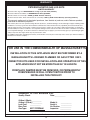
FOR USE IN THE COMMONWEALTH OF MASSACHUSETTS
INSTALLATION OF THIS APPLIANCE MUST BE PERFORMED BY A
MASSACHUSETTS LICENSED PLUMBER OR GAS FITTER ONLY.
CONNECTOR KITS USED FOR INSTALLATION AND OPERATION OF THIS
APPLIANCE MUST NOT BE MORE THAN 36” IN LENGTH.
FIREPLACE DAMPER MUST BE REMOVED, OR PERMANENTLY
FIXED/WELDED IN FULL OPEN POSITION PRIOR TO
INSTALLING THIS PRODUCT.
ROBERT H. PETERSON CO.
Quality Check
Date:___________
Orifice # (Main):__________
Orifice # (Other):__________
Leak Test:
___________
Burn Test:
___________
Gas Type:
NAT. / PROPANE
Model #:
___________
Serial #:
___________
Air Shutter: ___________
Inspector: ___________
Robert H. Peterson Co. • 14724 East Proctor Ave. • City of Industry, CA 91746
26