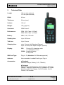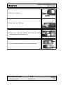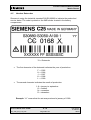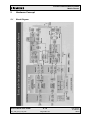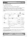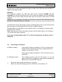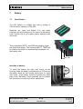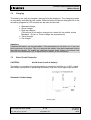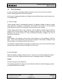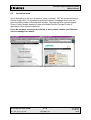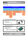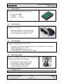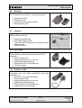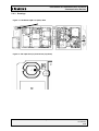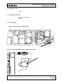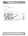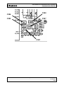
1
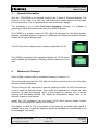
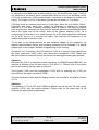
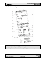
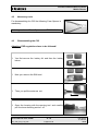
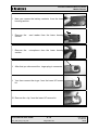
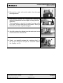
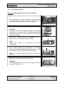
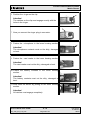
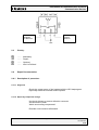
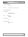
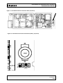
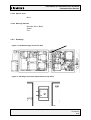
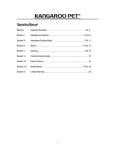
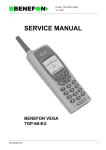
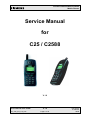
Private Communication Systems
Mobile Phones
Service Manual
for
C25 / C2588
V 1.0
Service Manual C25 / C2588
Sm_C25_lvl2_v10_w97
V 1.0
Page 1 of 32
ICP CD ST
R. Fleuren
02/99
Private Communication Systems
Mobile Phones
1
Introduction
The C25 is the first dualband handset (GSM-900 and GSM-1800) in the C-class.
The C2588 is a special version for the asian market featuring a graphic display instead of the
alphanumeric C25 display.
This manual is intended to help you carry out repairs up to level 2 on the mobile telephones
C25 and C2588.
For information on level 2.5 repairs or on the testequipment, please refer to the available
documentation.
The repairs for C25 and C2588 are identical unless otherwise noted, and therefor in the text
only C25 is mentioned.
Attention:
It must be noted that all repairs have to be carried out in an environment set up according to
the ESD (Electrostatic Discharge Sensitive Devices) regulations defined in international
standards.
If you have any questions or comments regarding repair procedures or this service manual,
please do not hesitate to contact the technical support team in Kamp-Lintfort, Germany:
(:
4:
::
Service Manual C25 / C2588
Sm_C25_lvl2_v10_w97
+49 2842 95 4666
+49 2842 95 4302
[email protected]
V 1.0
Page 2 of 32
ICP CD ST
R. Fleuren
02/99
Private Communication Systems
Mobile Phones
2
Table of Contents
1
INTRODUCTION ......................................................................................................................................... 2
2
TABLE OF CONTENTS .............................................................................................................................. 3
2
TECHNICAL DATA..................................................................................................................................... 5
3
GENERAL INFORMATION....................................................................................................................... 6
4
MECHANICAL CONCEPT ........................................................................................................................ 6
4.1
4.2
4.3
4.4
4.5
5
5.1
5.2
5.3
5.4
6
6.1
6.2
6.2
7
7.1
7.2
7.3
7.4
7.5
8
8.1
8.2
9
9.1
9.2
9.3
9.4
9.5
9.6
9.7
9.8
9.9
9.10
9.11
9.12
9.13
9.14
MECHANICAL DRAWING ........................................................................................................................... 8
NECESSARY TOOLS ................................................................................................................................... 9
DISASSEMBLING THE C25......................................................................................................................... 9
ASSEMBLING THE C25............................................................................................................................ 12
HANDSET DATECODES ........................................................................................................................... 15
HARDWARE CONCEPT .......................................................................................................................... 16
BLOCK DIAGRAM ................................................................................................................................... 16
HARDWARE DESCRIPTION ...................................................................................................................... 17
POWER SUPPLY CONCEPT ...................................................................................................................... 19
OVERVOLTAGE CONDITIONS .................................................................................................................. 20
SOFTWARE PROGRAMMING............................................................................................................... 21
HARDWARE OVERVIEW .......................................................................................................................... 21
DESCRIPTION OF SOFTWARE BOOTING .................................................................................................... 21
LANGUAGE GROUPS ............................................................................................................................... 22
BATTERY.................................................................................................................................................... 23
SPECIFICATION ....................................................................................................................................... 23
CHARGING.............................................................................................................................................. 24
SHORT CIRCUIT PROTECTION ................................................................................................................. 24
DEEP DISCHARGE ................................................................................................................................... 25
BATTERY DATECODES ........................................................................................................................... 26
UNBLOCKING ........................................................................................................................................... 27
SIEMENS HOTLINE .................................................................................................................................. 27
INTERNET SOLUTION............................................................................................................................... 28
ACCESSORIES........................................................................................................................................... 29
STANDARD CHARGER (INCLUDED IN PACKAGE)...................................................................................... 29
BATTERY (INCLUDED IN PACKAGE) ........................................................................................................ 29
SPARE BATTERY..................................................................................................................................... 30
RAPID CHARGER .................................................................................................................................... 30
TRAVEL CHARGER ................................................................................................................................. 30
DESK TOP CHARGER .............................................................................................................................. 30
DESIGNER CASES ................................................................................................................................... 30
BELT CLIP .............................................................................................................................................. 31
HEADSET ................................................................................................................................................ 31
CAR CRADLE .......................................................................................................................................... 31
ANTENNA CRADLE.................................................................................................................................. 31
CAR CHARGER ....................................................................................................................................... 32
CAR KIT PORTABLE ................................................................................................................................ 32
CAR KIT COMFORT ................................................................................................................................ 32
Service Manual C25 / C2588
Sm_C25_lvl2_v10_w97
V 1.0
Page 3 of 32
ICP CD ST
R. Fleuren
02/99
Private Communication Systems
Mobile Phones
9.15
CAR HANDSET........................................................................................................................................ 32
Service Manual C25 / C2588
Sm_C25_lvl2_v10_w97
V 1.0
Page 4 of 32
ICP CD ST
R. Fleuren
02/99
Private Communication Systems
Mobile Phones
2
Technical Data
Length:
116 mm (w/o antenna)
137 mm (with antenna)
Width:
46 mm
Thickness:
28 mm (max.)
Volume:
118 cm³
Weight:
130 g (approx.)
Standards:
GSM Phase 2
Performance:
GSM 900, Class 4 (2 Watt)
GSM 1800, Class 1 (1 Watt)
Battery:
NiMH, 3.6V, 700 mAh
Standby time:
Up to 100 hours
Talk time:
Up to 5 hours
Charging time:
up to 6 hours (with Standard Charger)
up to 1.5 hours (with Rapid Charger, optional)
Display:
C25:
SIM Card Type:
Plug-In, 3V (Attention: 5V-SIM not supported)
Antenna:
Non-retractable, Lambda/2 helix type, Plug-In
Accessories:
a) Standard:
Standard Charger, Battery (3.6V, 700mAh)
3 lines of 12 characters each
+ 1 dedicated icon-line
C2588: Graphical display
97*33 pixels
b) Optional:
Spare Battery, Rapid Charger, Travel Charger, Desk Top
Charger, Designer Cases, Belt Clip, Headset, Car Cradle,
Antenna cradle, Car Charger; Car Kit Portable, Car Kit
Comfort, Car Handset
Service Manual C25 / C2588
Sm_C25_lvl2_v10_w97
V 1.0
Page 5 of 32
ICP CD ST
R. Fleuren
02/99
Private Communication Systems
Mobile Phones
3
General Information
With the C25/C2588 is the second model of the C-class of Siemens Mobiles. The
intention of this class is to offer low cost entry-level mobile phones for the mass
consumer market. It is of a small size and has an attractive design.
This telephone is a so called Dual band telephone, meaning it is capable of
operating in GSM 900 networks as well as in GSM 1800 ones.
The C2588 is a special version of C25, which is designed for the asian market.
Besides a separate software version for C2588 the main difference between the two
models is the type of display used:
The C25 features an alphanumeric display comparable to C10.
The C2588 is equipped with a graphical display of 97*33 pixels,
which enables the telephone to display chinese characters to the
user.
4
Mechanical Concept
Note: All part numbers refer to mechanical drawing in section 4.1!
The mechanical concept of the C25 differs in various points from the one of the other
Siemens mobile telephones.
The first thing you will experience is how the housing is locked. In C25 no screws are
used to keep the housing closed. Also inside the telephone no screws are used
anymore. To open the housing, which is kept closed by catches only, a special
opening tool has been defined. For details on disassembly please refer to the
relevant chapter in this manual.
Inside, the C25 consists of just one board (1010) which carries display module
(1170), control part and RF section of the mobile.
The display module (1170) is connected to the board by a flexible cable which is
inserted into a plug. In case the display is defective electrically or mechanically it can
be exchanged very easily.
Service Manual C25 / C2588
Sm_C25_lvl2_v10_w97
V 1.0
Page 6 of 32
ICP CD ST
R. Fleuren
02/99
Private Communication Systems
Mobile Phones
In opposite to the MMI board of other phones (e.g. S6 and E10) the ringer (1100) is
not soldered to the board, but is mechanically fixed on one of the shielding covers
(1310) by a metal clip (1190) and electrically connected to the board by a cable and
a plug. The ringer in C25 is of the same type as the one used in C1x mobiles.
C25 does have an external connector of a new type. Since S6 a so called „Molex“connector was used, which also offered the possibility to connect an external
antenna to it. The new „Lumberg“-connector which is used in C25 does not feature
such a connection, because the connector for external antenna is located at the back
side of the upper end of the mobile, close to the internal antenna (1130). As a
consequence of this there is no need anymore for a RF cable mounted to the board
nor for a RF plug on it to connect this cable. This improves RF-properties of the
mobile and lowers production costs.
To be able to do measurements on and software update of the telephone, an
adapter cable between Molex- and Lumberg connector will be available. For details
please refer to the chapter Software Programming of this manual.
As already for C1x mobiles, also C25 antenna (1130) is of a plug-in type inserted into
the lower case shell (1030), which also carries the microphone (1110). Make sure
that the microphone contact springs are not dirty or damaged during repair process.
Attention:
Because the C25 is a dual-band mobile operating on GSM900 and GSM1800, the
antenna is different from the one used in C10 and C11. Please refer to the spare
part list for ordering the right type of antenna!
The keypad (1150) and the loudspeaker (1120) with it’s retaining clip (1125) are
mounted into the upper case shell (1020).
The dust protection frame and the display window are included in the display module
(1170).
Attention:
The displays (1170) of C25 and C2588 are different as well as their RF-and control
modules (1010) and the mobile software. Please refer to the spare part list for
ordering the appropriate components!
Service Manual C25 / C2588
Sm_C25_lvl2_v10_w97
V 1.0
Page 7 of 32
ICP CD ST
R. Fleuren
02/99
Private Communication Systems
Mobile Phones
4.1
Mechanical drawing
Note:
The numbers shown above are NO ordering numbers.
For ordering please use the partnumbers supplied by your service manager!
Service Manual C25 / C2588
Sm_C25_lvl2_v10_w97
V 1.0
Page 8 of 32
ICP CD ST
R. Fleuren
02/99
Private Communication Systems
Mobile Phones
4.2
Necessary tools
For disassembling the C25 the following Case Opener is
mandatory:
Ordering number of Case Opener:
4.3
F30032-P46-A1
Disassembling the C25
Attention: ESD regulations have to be followed!
1. You first remove the battery lid and then the battery
below.
2. Now you remove the SIM card.
3. Then you pull the antenna out.
4. Open the housing with the opening tool and carefully
pull the lower housing section off.
Service Manual C25 / C2588
Sm_C25_lvl2_v10_w97
V 1.0
Page 9 of 32
ICP CD ST
R. Fleuren
02/99
Private Communication Systems
Mobile Phones
5. Now you remove the battery contacts from the lower
housing section.
6. Remove the
section.
card reader from the lower housing
7. Remove the
section.
microphone from the lower housing
8. After that you disconnect the ringer plug-in connector.
9. You then remove the ringer from the lower HF-screen
lid.
10. Remove the clip from the lower HF-screen lid.
Service Manual C25 / C2588
Sm_C25_lvl2_v10_w97
V 1.0
Page 10 of 32
ICP CD ST
R. Fleuren
02/99
Private Communication Systems
Mobile Phones
11. Remove the radio and control module from the upper
housing section.
12. After that you remove the keypad mat, retaining clip
and the loudspeaker from the upper housing section.
Attention:
The loudspeaker is glued to the upper housing section
by a foam covered with glue on both sides. When you
remove it, the foam may be damaged.
13. Carefully release the display from the radio and control
module and fold it downwards.
1
14. Finally, you carefully release the retaining clip (1) of
the plug-in connector and pull the connector cable of
the display out (2).
2
Service Manual C25 / C2588
Sm_C25_lvl2_v10_w97
V 1.0
Page 11 of 32
ICP CD ST
R. Fleuren
02/99
Private Communication Systems
Mobile Phones
4.4
Assembling the C25
Attention: ESD regulations have to be followed!
2
1. First you plug in the connector cable of the display in
the retaining clip of the plug-in connector on the
module (1) and then close the retaining clip (2).
1
2. Now fasten the display to the radio and control module.
Attention!
In order to position the display exactly, the synthetic
projection on the lower side of the display frame must
be fitted into the hole in the screen lid. The catches
must fully engage.
3. Place the
keypad mat, the loudspeaker and its
retaining clip in the upper housing section.
Note:
Please first remove the protective foil from the
loudspeaker.
4. Then check whether the HF-screens
have been
properly secured. Subsequently you place the
radio
and control module in the upper housing section.
Note: On the MMI's display side there is a further RFscreen.
5. Place the clip on the lower HF-screen lid.
Attention!
The metal projection on the clip must engage with the
recess in the screen lid.
Service Manual C25 / C2588
Sm_C25_lvl2_v10_w97
V 1.0
Page 12 of 32
ICP CD ST
R. Fleuren
02/99
Private Communication Systems
Mobile Phones
6. Position the ringer on the clip.
Attention!
The catches on the clip must engage exactly with the
holes in the ringer.
7. Now you connect the ringer plug-in connector .
8. Fasten the microphone in the lower housing section.
Attention!
The microphone contacts must not be dirty, damaged
or bent.
9. Fasten the card reader in the lower housing section.
Attention!
The card reader must not be dirty, damaged or bent.
10. Fasten the battery contacts in the lower housing
section.
Attention!
The battery contacts must not be dirty, damaged or
bent.
11. Now close the device by putting on the lower housing
section.
Attention!
All catches must engage completely.
Service Manual C25 / C2588
Sm_C25_lvl2_v10_w97
V 1.0
Page 13 of 32
ICP CD ST
R. Fleuren
02/99
Private Communication Systems
Mobile Phones
12. Push the antenna in.
13. Now insert the SIM card.
14. Finally you insert the battery and close the battery
compartment with the battery lid.
15. Now you have assembled the phone completely.
Service Manual C25 / C2588
Sm_C25_lvl2_v10_w97
V 1.0
Page 14 of 32
ICP CD ST
R. Fleuren
02/99
Private Communication Systems
Mobile Phones
4.5
Handset Datecodes
Siemens is using the industrial standard DIN EN 60062 to indicate the production /
service dates. The code is printed on the IMEI sticker located in the battery
compartment.
YY = Datecode
•
The first character of the datecode indicates the year of production:
F
H
J
K
L
•
= 1995
= 1996
= 1997
= 1998
= 1999
The second character indicates the month of production:
1-9
O
N
D
= january to september
= october
= november
= december
Example: “L1” means that the set was produced in january of 1999.
Service Manual C25 / C2588
Sm_C25_lvl2_v10_w97
V 1.0
Page 15 of 32
ICP CD ST
R. Fleuren
02/99
Private Communication Systems
Mobile Phones
5
Hardware Concept
5.1
Block Diagram
Service Manual C25 / C2588
Sm_C25_lvl2_v10_w97
V 1.0
Page 16 of 32
ICP CD ST
R. Fleuren
02/99
Private Communication Systems
Mobile Phones
5.2
Hardware Description
The handset consists of the following major integrated circuits:
1) HiGOLD (PMB 2800)
This IC is a combination of microprocessor and signalprocessor.
The microprocessor part of this component is responsible for controlling the
keyboard, SIM-Card, Flash and RAM. Furthermore it controls the power up/power
down of the RF module and sets the amplification of the PA.
The signal processor part of PMB 2800 is responsible for processing the Rx I/Q
signals (filtering, equalizing, speech and channel decoding).
Furthermore it does the speech and channel encoding and the GSMK modulation of
the Tx I/Q signals.
2) GOLD-SX (PMB 2709)
The coprocessor PMB 2709 is used to realize advanced features regarding coding
of the speech signal. These are:
•
•
•
•
•
•
Halfrate-Encoding
Halfrate-Decoding
Enhanced Fullrate Encoding
Enhanced Fullrate Decoding
Voice Activity Detection
Comfort Noise
3) GAIM (PMB 2905)
The GAIM (GAIM = GSM Analog Interfacing Module) provides the interface between
the analogue signals (I/Q, voiceband, PA-control, charging control signals) and its
digital representation.
4) Receiver Circuit (PMB 2411)
This circuit provides the following main functionalities:
•
•
•
Low Noise Amplifier (LNA) with a fixed amplification of +20dB to amplify
the input RF signal.
Mixer to mix down the RF signal to the Intermediate Frequency (IF)
Programmable IF amplifier with a dynamic range of 60dB ( -10dB ...
+50dB in steps of 2dB).
Service Manual C25 / C2588
Sm_C25_lvl2_v10_w97
V 1.0
Page 17 of 32
ICP CD ST
R. Fleuren
02/99
Private Communication Systems
Mobile Phones
•
•
Mixer to mix down the IF signal to the baseband, generating and
inphase (I) and a quadrature (Q) signal.
Offset compensation for the I/Q signals.
5) Transmitter Circuit PMB 2255
This circuit provides the IF synthesizer, the I/Q modulator, prescalers to regulate the
RF synthesizer and a buffer stage to feed the PA.
The antenna switch is mechanical, located in the connector for the external antenna.
Service Manual C25 / C2588
Sm_C25_lvl2_v10_w97
V 1.0
Page 18 of 32
ICP CD ST
R. Fleuren
02/99
Private Communication Systems
Mobile Phones
5.3
Power Supply Concept
The C25 has two main power inputs:
1) Battery Voltage (3.6 Volts) connected at the battery contacts
2) Charging Voltage (6.5 Volts) delivered by the different charger types (see
accessory list) via the Lumberg connector at the bottom of the telephone.
Since the battery voltage is supplying the power supply asic, it is always needed to
operate the phone. You cannot switch on the handset if the battery voltage is not
present.
From the battery voltage all other supply voltages of the C25 are derived, controlled
by the power supply ASIC.
The RF power amplifier needs an operation voltage of 5,4Volts, which is generated
by a DC-DC step-up converter.
The logic module uses 2.9 V, generated by a regulator inside the ASIC.
Service Manual C25 / C2588
Sm_C25_lvl2_v10_w97
V 1.0
Page 19 of 32
ICP CD ST
R. Fleuren
02/99
Private Communication Systems
Mobile Phones
Furthermore the ASIC generates the supply voltage for the SIM card and the RESET
signal for the logic devices.
Attention:
The telephone supplies the SIM card with 3Volts, meaning 5V-SIMs are not
supported. In case a user inserts such a 5Volt card, the telephone will not recognise
it and prompt to insert a SIM card the same way as it would in case there is no SIM
inserted.
Telephone is not defective. The way to solve this is to get the SIM exchanged by the
operator or service provider to a 3V type.
The ASIC also checks the presence of the watchdog signal from the µP and provides
the switching on functionality (ON_OFF button or Ignition signal).
During testing ist is advisable to use a battery dummy, connected to a power supply
delivering +4V, max 3A.
Make sure that you connect the battery dummy with the right polarity, the red plug to
+4V and the blue plug to ground.
If you use a voltage higher than +7V, or with wrong polarity, the phone can be
damaged!
5.4
Overvoltage Conditions
a) Battery Voltage:
If the supply voltage rises above 6.2 Volts, the phone will
switch off and it cannot be switched on again before the
voltage is lower than 6.2 Volts.
If the supply voltage rises above 7 Volts the phone can be
destroyed.
b) Charging Current:
ã
ã
The charging current must not rise above 1 A or the
phone (fuse) will be inoperable, meaning that charging the
battery will not be possible anymore.
Be careful with foreign accessories or chargers!
Make sure that the charging current is limited to a value below 1A!
Service Manual C25 / C2588
Sm_C25_lvl2_v10_w97
V 1.0
Page 20 of 32
ICP CD ST
R. Fleuren
02/99
Private Communication Systems
Mobile Phones
6
Software programming
6.1
Hardware overview
Connection
Cable
RS-232
Adapter
Cable
Bootadapter
AC-Adapter
The software of the C25 handset is programmed directly from a PC using a
bootadapter as an interface between serial port of the PC and the mobile. Because
of the new type of external connector used in C25 (Lumberg type) an additional
adapter cable between mobile and bootadapter is required.
6.2
Description of software booting
F
Connect COM-port of PC to the bootadapter using the enclosed RS232-cable.
F
Connect adapter cable to the connection cable of the bootadapter.
F
Afterwards plug in AC-Adapter: If connected correctly the “Power” lamp on the
bootadapter will be active.
F
Switch off the handset and connect it to the adapter cable.
F
Copy bootsoftware to the PC and follow the instructions in the file “readme.txt”.
Ordering number of Adapter cable: V30146-A5004-D
Ordering number of Bootadapter:
Service Manual C25 / C2588
Sm_C25_lvl2_v10_w97
L24857-F1006-A30
The bootadapter comes complete with ACAdapter, RS-232 and handset connection cable.
V 1.0
Page 21 of 32
ICP CD ST
R. Fleuren
02/99
Private Communication Systems
Mobile Phones
6.2
Language Groups
For C25/C2588 the following languages will be available. They will be separated into
different language groups.
Bahasan Indonesia
Cestina
English
German
Italian
Portu
Swedish
Bahasan Malaysia
Danish
Finnish
Greek
Norsk
Russian
Turkish
Catalan
Dutch
French
Hungar
Polish
Spanish
Attention:
This information is subject to change! Contact your service coordinator for the latest
update and ordering numbers.
Service Manual C25 / C2588
Sm_C25_lvl2_v10_w97
V 1.0
Page 22 of 32
ICP CD ST
R. Fleuren
02/99
Private Communication Systems
Mobile Phones
7
Battery
7.1
Specification
The C25 battery is a NiMH type with a voltage of
3.6Volts and a capacity of 700 mAh.
Suppliers are Varta and Maxell. You can easily
recognize the manufacturer by the colour of the battery
cells: Varta’s cells are of a green colour, Maxell’s ones
are bluish.
The connections BATT+ and GND are used to supply
the phone with power. The connector BATT_TEMP can
be used by the mobile to measure the temperature of
the battery cells.
BATT+
Batt_Temp
GND
Insertion of battery:
To insert the battery the right way round, on the
housing inside the battery compartment of C25 and on
the battery there are two arrows, which have to mach
each other. If the battery would be inserted any other
way round, the battery cover probably can be closed,
but the phone of course will not be operational.
Service Manual C25 / C2588
Sm_C25_lvl2_v10_w97
V 1.0
Page 23 of 32
ICP CD ST
R. Fleuren
02/99
Private Communication Systems
Mobile Phones
7.2
Charging
The battery can only be charged if inserted into the telephone. The charging process
is completely controlled by the mobile. Different kinds of Siemens chargers out of the
accessory program for C25 models can be used for this task:
Ø Standard charger
Ø Quick charger
Ø Desk top charger
(This device is not really a charger but a stand for the mobile, where
Standard- , Quick- or Travel charger are connected to)
Ø Travel charger
Ø Car charger
Attention:
Charging the battery can be impossible, if the temperature is too high (e.g. in car use
during summer) or too low. This is to prevent the battery from being damaged during
fast charge process. To enable the charging process again, battery and phone only
needs to cool down/warm up. A replacement of battery is not necessary.
7.3
Short Circuit Protection
CAUTION:
Avoid short circuit of battery !
The battery is not short-circuit protected by an electronic fuse like e.g. in S10. Inside
the battery a polyswitch is protecting the battery cells from a too high output current.
Schematic of the battery:
Service Manual C25 / C2588
Sm_C25_lvl2_v10_w97
V 1.0
Page 24 of 32
ICP CD ST
R. Fleuren
02/99
Private Communication Systems
Mobile Phones
7.4
Deep Discharge
In case of a deeply discharged battery, the phone can not be turned on and the
normal charging process can not be started.
In this case, charging the battery is divided into two different steps, which have to be
run subsequently:
a) Trickle charge
Trickle charge mode is automatically started if the battery voltage is below a certain
value when the charger is connected to the mobile. This mode is not terminated
automatically but has to be terminated by disconnecting the charger.
Trickle charge mode has to last minimum until the battery voltage has exceeded a
certain level. During trickle charge the charging symbol will not be visible and the
telephone can not be turned on. This is because the battery voltage is too low to
operate the telephone
Action:
Insert battery into handset and connect travel charger to the telephone. Wait for
appr. 1 hour, then disconnect and reconnect charger. If the battery voltage is high
enough again, the charging symbol will come up.
If the battery is discharched very deeply, the symbol may not come up and the trickle
charge time possibly has to be extended up to 24 hours.
b) Normal charge
When the battery voltage is above the a.m. value (e.g. by trickle charge) the mobile
will start the normal charging mode and show a charging symbol in the display.
Action:
Connect charger to the telephone.
The charging symbol will come up as an indication that the normal charging process
has been started by the mobile.
Service Manual C25 / C2588
Sm_C25_lvl2_v10_w97
V 1.0
Page 25 of 32
ICP CD ST
R. Fleuren
02/99
Private Communication Systems
Mobile Phones
7.5
Battery Datecodes
There are two different suppliers of the C25 batteries and they use different kinds of
codes to give information about production date:
a) Maxell batteries
The datecode printed on the battery looks like this:
K 7 08 20 M
Explanation:
K
7
08
20
M
= Year of production
(1998=K, 1999=L)
= Month of production
(Jan=1, Feb=2, .....Oct=O, Nov=N, Dec=D)
= Day of production
(1st =1, 2nd =2, 3rd =3,........, 31st=31)
= Week of cell-production
= Factory code (M=UK, E= Germany)
Example:
This battery was produced on July 8th of 1998!
K 7 08 20 M
b) Varta batteries
The datecode printed on the battery looks like this:
TOS 8 G9 VA 1
Explanation:
TOS
8
G
9
VA
1
= Battery cells supplied by Toshiba
= Revision level
= Year of production (1997=J, 1998=K, 1999=L)
= Month of production (Jan=1, Feb=2, .....Oct=O, Nov=N, Dec=D)
= Varta (battery manufacturer)
= Place of manufacturing (1=Germany ,2= Novibor, Czech Republic)
Example:
TOS 8 K4 VA 1
Service Manual C25 / C2588
Sm_C25_lvl2_v10_w97
This battery was produced in april of 1998!
V 1.0
Page 26 of 32
ICP CD ST
R. Fleuren
02/99
Private Communication Systems
Mobile Phones
8
Unblocking
If the phone is disabled due to a wrong entry of the phonecode (not PIN1, PIN2,
network code or service provider code!) it can only be resetted by entering the right
unblocking code.
This unblocking code is derived from the IMEI number of the mobile and can only be
calculated in two different ways:
8.1
Siemens Hotline
You can retreive the code from our hotline personell in Germany.
If you need unblocking codes just send a fax with the IMEI numbers to:
Siemens AG
PN MP SH
World Service Center
Bocholt, Germany
Fax: +49 2871 91 3007
Please use the appropriate form provided by your Siemens service coordinator.
Service Manual C25 / C2588
Sm_C25_lvl2_v10_w97
V 1.0
Page 27 of 32
ICP CD ST
R. Fleuren
02/99
Private Communication Systems
Mobile Phones
8.2
Internet solution
As an alternative to the a.m. procedure, since november 1997 an internet solution is
offered to the LSO. It is a password protected internet homepage where you can
enter the IMEI number of the affected handset. The page will then present Master
Phone Codes, Master Network Codes and Master Service Provider Codes (if
applicable to the relevant telephone).
If you do not have access to this tool up to now, please contact your Siemens
service manager for details.
Service Manual C25 / C2588
Sm_C25_lvl2_v10_w97
V 1.0
Page 28 of 32
ICP CD ST
R. Fleuren
02/99
Private Communication Systems
Mobile Phones
9 Accessories
Overview of optional accessories:
Mobile Phone Accessory Program
Batteries
Battery
700 mAh
Charging
Car Environment
Rapid
Charger
Car
Charger
Antenna
Cradle
Travel
Charger
Car
Cradle
Car Kit
Comfort
Desktop
Solutions
Desk Top
Charger
Design
& Carry
Headset
Belt Clip
Leather
Case
Car Kit Portable
9.1
Standard Charger (included in package)
Specifications:
Ø Voltage: 6.0Volts
Ø Current: 150mA
Ø Charging time: Up to 5 hours
9.2
Battery (included in package)
Specifications:
Ø NiMH, 3.6V, 700mAh
Ø Standby time: up to 100 hours
Ø Talk time: up to 5 hours
Ø Charging time:
Approx. 5 hours with Standard charger
Approx. 1.5 hours with Rapid charger
Service Manual C25 / C2588
Sm_C25_lvl2_v10_w97
V 1.0
Page 29 of 32
ICP CD ST
R. Fleuren
02/99
Private Communication Systems
Mobile Phones
9.3
Spare Battery
Identical to the one supplied with the phone
Ø Technology: NiMH
Ø Voltage:
3.6V
Ø Capacity:
700mAh
9.4
Rapid Charger
The rapid charger speeds up the charging process to
a duration of 1.5 hours.
Ø Compact charger in 5 country versions
(EU, UK, US/ Taiwan, China, Australia)
Ø Quick charging time: approx. 1.5 hrs
9.5
Travel Charger
The Travel Charger is similar to the Rapid Charger, but enables the user to use the
worldwide voltage range of 90-270 Volts.
Ø Compact size; 5 versions available (EU, UK, US/ Taiwan, China, Australia)
Ø Operating voltage: 90 – 270V
Ø Quick charging time: approx. 1.5 hrs
Ø Power supply for: Phone, Desk Top Charger
9.6
Desk Top Charger
The desktop charger forms a convenient stand for the
mobile. It enables „easy drop in charging“ and
connects to all available C25 chargers.
Ø
Ø
Ø
Ø
Small attractive design fitting to C25
Comfortable charging of the phone
Power supply by Rapid Charger,
Travel Charger, Car Charger
9.7
Designer Cases
A range of attractive protective cases for the telephone will be available.
Service Manual C25 / C2588
Sm_C25_lvl2_v10_w97
V 1.0
Page 30 of 32
ICP CD ST
R. Fleuren
02/99
Private Communication Systems
Mobile Phones
9.8
Belt Clip
The belt clip allows easy and secure attachement to a
belt. The phone can rotate to a convenient angle.
Ø
Ø
Ø
Ø
Rotatable fixation
Easy to remove
Insertion in each angle possible
Secure phone hold
9.9
Headset
The headset offers safe hifh quality hands free use
whilst walking or driving.
Ø Portable Handsfree Kit
Ø Full duplex digital quality
Ø Automatic call acceptance controlled by mobile
phone menue
Ø Comfort fixation
9.10 Car Cradle
The car cradle is supplied with an adjustable bracket.
This enables secure and convenient siting of the
telephone.
Ø Secure phone hold
Ø Safety supplement for in car use
Ø Individual angle positioning
Ø Park position for Car Charger etc.
Ø Comfort release
9.11 Antenna cradle
This robust cradle provides simple automatic
connection, use with other accessories and easy
handheld use.
Ø Connection for external antenna
Ø Secure phone hold
Ø Safety supplement for in car use
Ø Individual angle positioning
Ø Park Position for Car Charger etc.
Ø Support privacy functionality
Service Manual C25 / C2588
Sm_C25_lvl2_v10_w97
V 1.0
Page 31 of 32
ICP CD ST
R. Fleuren
02/99
Private Communication Systems
Mobile Phones
9.12 Car Charger
Ø Power supply and battery charging
Ø Quick charging with auto switch over to trickle
charging
Ø Power supply for Desk Top Charger
Ø Connection to cigar lighter (12V/24V)
Ø LED signalizing power supply
Ø Recommended use together with Car Cradle
9.13
Ø
Ø
Ø
Ø
Ø
Ø
Ø
Ø
Ø
Car Kit Portable
High quality (duplex) handsfree
Power supply and charging
Installation in cigar lighter ( 12 V )
Automatic call acceptance
Permanent display illumination
Volume control over side key or on mobile
Rotatable speaker
Variable microfone positioning
LED indicates function mode
9.14
Ø
Ø
Ø
Ø
Ø
Ø
Ø
Ø
Car Kit Comfort
High quality duplex handsfree
Power supply and battery charging
Radio mute
Auto answer on / off
Ignition detection
Permanent display illumination
Auto power off via ignition switch
Seperate E-Box with plug and play
connections
Ø Universal connector for external antenna
Ø Private functionality (via Car Handset)
Ø Secure phone hold
9.15 Car Handset
Ø
Ø
Ø
Ø
Additional handset for private calls
Direct call acceptance by lifting up handset
Volume control directly on the handset
Curley Cord
Ø Plug and play connector to handsfree unit
Service Manual C25 / C2588
Sm_C25_lvl2_v10_w97
V 1.0
Page 32 of 32
ICP CD ST
R. Fleuren
02/99
Information and Communication Products
Communication Devices
C25(88)
Level 2.5
Repair Documentation
V 1.2
V1.2
Page 1 of 34
ICP CD ST
D. Schnoor
8/99
Information and Communication Products
Communication Devices
1 Introduction
The C25 is the first dualband handset (GSM-900 and GSM-1800) in the C-class.
The C2588 is a special version for the asian market featuring a graphic display instead of the
alphanumeric C25 display.
The repairs for C25 and C2588 are identical unless otherwise noted.
Lately a new version of the C25 has been introduced. This version has the main processor
HiGold version 4.3 of the S25(88). Internally this C25 is therefore called C25V4. The level
2.5 parts are identical to the old C25 version.
This manual is intended to help you carry out repairs on level 2.5, meaning limited
component repairs. Failure highlights are documented and should be repaired in the local
workshops.
It must be noted that all repairs have to be carried out in an environment set up according to
the ESD (Electrostatic Discharge Sensitive Devices) regulations defined in international
standards.
If you have any questions regarding the repair procedures or spare parts do not hesitate to
contact our technical support team in Kamp-Lintfort, Germany:
Tel.: +49 2842 95 4666
Fax: +49 2842 95 4302
e-mail: [email protected]
V1.2
Page 2 of 34
ICP CD ST
D. Schnoor
8/99
Information and Communication Products
Communication Devices
Table of Contents:
1
INTRODUCTION ......................................................................................................................................... 2
2
ANTENNA CONNECTOR .......................................................................................................................... 4
3
RINGER CONNECTOR .............................................................................................................................. 8
4
BOTTOM CONNECTOR (LUMBERG).................................................................................................. 11
5
18µH COIL .................................................................................................................................................. 14
6
ANTENNA SPRING ................................................................................................................................... 18
7
DISPLAY CONNECTOR........................................................................................................................... 21
8
DISPLAY CAPACITORS .......................................................................................................................... 25
9
RINGER COIL............................................................................................................................................ 29
10
V1.2
KEYPAD LEDS....................................................................................................................................... 32
Page 3 of 34
ICP CD ST
D. Schnoor
8/99
Information and Communication Products
Communication Devices
2 Antenna Connector
2.1
Affected Units
2.1.1 Type:
C25
2.1.2 Affected IMEIs / Date Codes:
All / All
2.1.3 Affected SW-Versions:
All
2.1.4 Fault Code for LSO reporting:
3ANC
2.2
Fault Description
2.2.1 Fault Symptoms for customers:
Network Search when using the external antenna
(carkit)
No location update possible on external antenna (carkit)
2.2.2 Fault Symptom on GSM-Tester:
Output power problems on the external antenna
No location update possible
2.2.3 Component Information
The Antenna Connector is a mechanical switch operated by the RF plug of a carkit or, for testing
purposes, of an RF clip.
Normally the RF signal goes to and comes from the internal antenna. Whenever an RF plug is plugged
into the antenna connector the connection to the internal antenna is openend and the connection to the
external antenna socket is made. See drawing below.
V1.2
Page 4 of 34
ICP CD ST
D. Schnoor
8/99
Information and Communication Products
Communication Devices
From Power
Amplifier/
To Receiver
2.3
p
x
p
p
2.4
To / From
Internal
Antenna
Priority:
........ Mandatory
........ Repair
........ Optional
........ Not Yet Defined
Repair Documentation
2.4.1 Description of procedure:
2.4.1.1 Diagnosis
Check the output power of the handset with the LSO testprogram.
Especially watch the external antenna power!
2.4.1.2 Repair by component change
Use hot air blower to remove defective connector
Avoid excessive heat!
Watch surrounding components!
Resolder new connector afterwards.
V1.2
Page 5 of 34
ICP CD ST
D. Schnoor
8/99
Information and Communication Products
Communication Devices
2.4.1.3 Repair by SW-Booting
Not possible!
2.4.1.4 Test
Retest handset after repair as described above.
2.4.2 List of needed material
2.4.2.1 Components
C25 antenna connector
Part-Number: L36334-Z93-C261
2.4.2.2
Jigs and Tools
Hot Air Blower
Soldering Iron
2.4.2.3 Special Tools
None
2.4.2.4 Working materials
Desolder Wick / Braid
Solder
V1.2
Page 6 of 34
ICP CD ST
D. Schnoor
8/99
Information and Communication Products
Communication Devices
2.4.3 Drawings
Figure 1: C25 Board Antenna Connector Side (Top View)
Figure 2: C25 Antenna Connector Placement (X400) (Top View)
V1.2
Page 7 of 34
ICP CD ST
D. Schnoor
8/99
Information and Communication Products
Communication Devices
3 Ringer Connector
3.1
Affected Units
3.1.1 Type:
C25
3.1.2 Affected IMEIs / Date Codes:
All / All
3.1.3 Affected SW-Versions:
All
3.1.4 Fault Code for LSO reporting:
3RIC
3.2
Fault Description
3.2.1 Fault Symptoms for customers:
Problems with the handset ringer. No ringer tone
audible.
3.2.2 Fault Symptom on GSM-Tester:
Handset fails ringer test.
3.3
p
x
p
p
V1.2
Priority:
........ Mandatory
........ Repair
........ Optional
........ Not Yet Defined
Page 8 of 34
ICP CD ST
D. Schnoor
8/99
Information and Communication Products
Communication Devices
3.4
Repair Documentation
3.4.1 Description of procedure:
The connector X5 is connecting the main board of the C25 with the piezo
ringer through a two pin cable.
3.4.1.1 Diagnosis
Visually check the connector. Watch for bent contacts and dry joints.
3.4.1.2 Repair by component change
Resolder dry soldering joints.
If the connector is physically damaged use hot air blower or wick to remove
defective connector.
Avoid excessive heat!
Watch surrounding components!
Resolder new connector afterwards.
3.4.1.3 Repair by SW-Booting
Not possible!
3.4.1.4 Test
Retest handset after repair.
3.4.2 List of needed material
3.4.2.1 Components
Ringer Connector C25:
Part-Number: L36334-Z97-C43
3.4.2.2 Jigs and Tools
Hot Air Blower
Soldering Iron
V1.2
Page 9 of 34
ICP CD ST
D. Schnoor
8/99
Information and Communication Products
Communication Devices
3.4.2.3 Special Tools
None
3.4.2.4 Working materials
Desolder Wick / Braid
Solder
Flux
3.4.3 Drawings
Figure 1: C25 Board Ringer Connector Side
Figure 2: C25 Ringer Connector (X5) Placement (Top View)
V1.2
Page 10 of 34
ICP CD ST
D. Schnoor
8/99
Information and Communication Products
Communication Devices
4 Bottom Connector (Lumberg)
4.1
Affected Units
4.1.1 Type:
C25
4.1.2 Affected IMEIs / Date Codes:
All / All
4.1.3 Affected SW-Versions:
All
4.1.4 Fault Code for LSO reporting:
3LUC
4.2
Fault Description
4.2.1 Fault Symptoms for customers:
Charging problems.
Problems with external loudspeaker or microphone
when using a car kit.
Problems with accessories connected at the bottom
connector.
4.2.2 Fault Symptom on GSM-Tester:
Testequipment cannot communicate with the handset.
4.3
p
x
p
p
V1.2
Priority:
........ Mandatory
........ Repair
........ Optional
........ Not Yet Defined
Page 11 of 34
ICP CD ST
D. Schnoor
8/99
Information and Communication Products
Communication Devices
4.4
Repair Documentation
4.4.1 Description of procedure:
4.4.1.1 Diagnosis
Visually check the bottom connector. Watch for dry joints!
4.4.1.2 Repair by component change
Use hot air blower remove defective bottom connector.
Avoid excessive heat!
Watch surrounding components!
Resolder new bottom connector afterwards.
4.4.1.3 Repair by SW-Booting
Not possible!
4.4.1.4 Test
Retest handset after repair.
4.4.2 List of needed material
4.4.2.1 Components
Bottom Connector C25
Part-Number: L36334-Z93-C262
4.4.2.2 Jigs and Tools
Hot Air Blower
Soldering Iron
4.4.2.3 Special Tools
None
V1.2
Page 12 of 34
ICP CD ST
D. Schnoor
8/99
Information and Communication Products
Communication Devices
4.4.2.4 Working materials
Desolder Wick / Braid
Solder
4.4.3 Drawings
Figure 1: C25 Board Bottom Connector Side
Figure 2: C25 Bottom Connector (X4) Placement (Top View)
V1.2
Page 13 of 34
ICP CD ST
D. Schnoor
8/99
Information and Communication Products
Communication Devices
5 18µH Coil
5.1
Affected Units
5.1.1 Type:
C25
5.1.2 Affected IMEIs / Date Codes:
All / All
5.1.3 Affected SW-Versions:
All
5.1.4 Fault Code for LSO reporting:
3COI
5.2
Fault Description
5.2.1 Fault Symptoms for customers:
Loud humming noise in loudspeaker.
5.2.2 Fault Symptom on GSM-Tester:
Handset fails with loud humming noise in echo loop.
5.3
p
x
p
p
V1.2
Priority:
........ Mandatory
........ Repair
........ Optional
........ Not Yet Defined
Page 14 of 34
ICP CD ST
D. Schnoor
8/99
Information and Communication Products
Communication Devices
5.4
Repair Documentation
5.4.1 Description of procedure:
5.4.1.1 Diagnosis
The 18µH coil is used in the step up converter which is generating a
5.4 V supply voltage for the power amplifier out of the 2.8V battery
voltage.
If the coil is mechanically damaged (broken) it produces heavy
interference with the acoustical elements of the C25 resulting in a loud
humming noise in the earpiece.
A broken coil can easily be diagnosed by trying to move it with two
fingers. If it moves, the core is broken and the coil has to be
replaced.
5.4.1.2 Repair by component change
Use hot air to remove defective coil.
Avoid excessive heat!
Watch surrounding components!!
Resolder new coil afterwards
5.4.1.3 Repair by SW-Booting
Not possible!
5.4.1.4 Test
Retest handset after repair by checking the audio quality with the echo
loop of the testprogram.
V1.2
Page 15 of 34
ICP CD ST
D. Schnoor
8/99
Information and Communication Products
Communication Devices
5.4.2 List of needed material
5.4.2.1 Components 18µH Coil
Part-Number: L36151-F5183-M
5.4.2.2 Jigs and Tools
Soldering Iron
Hot Air Blower
5.4.2.3 Special Tools
None
5.4.2.4 Working materials
Desolder Wick / Braid
Solder
V1.2
Page 16 of 34
ICP CD ST
D. Schnoor
8/99
Information and Communication Products
Communication Devices
5.4.3 Drawings
Figure 1: C25 Board 18µH Coil (L201) Side
Figure 2: C25 18µH Coil (L1) Placement (Top View)
V1.2
Page 17 of 34
ICP CD ST
D. Schnoor
8/99
Information and Communication Products
Communication Devices
6 Antenna Spring
6.1
Affected Units
6.1.1 Type:
C25
6.1.2 Affected IMEIs / Date Codes:
All / All
6.1.3 Affected SW-Versions:
All
6.1.4 Fault Code for LSO reporting:
3ANS
6.2
Fault Description
6.2.1 Fault Symptoms for customers:
Network Search.
Handset drops calls.
6.2.2 Fault Symptom on GSM-Tester:
Power problems on the internal antenna of the handset
only.
6.3
p
x
p
p
V1.2
Priority:
........ Mandatory
........ Repair
........ Optional
........ Not Yet Defined
Page 18 of 34
ICP CD ST
D. Schnoor
8/99
Information and Communication Products
Communication Devices
6.4
Repair Documentation
6.4.1 Description of procedure:
The antennaspring connects the main board with the internal antenna
of the handset.
6.4.1.1 Diagnosis
Visually check the status of the spring. Bent or oxidated springs have
to be replaced.
6.4.1.2 Repair by component change
Use soldering iron to remove defective spring.
Avoid excessive heat!
Watch surrounding components!
Resolder new spring afterwards.
6.4.1.3 Repair by SW-Booting
Not possible!
6.4.1.4 Test
Retest handset after repair.
6.4.2 List of needed material
6.4.2.1 Components
Antenna Spring C25
Part-Number: L36158-A25-C9
6.4.2.2 Jigs and Tools
Hot Air Blower
Soldering Iron
V1.2
Page 19 of 34
ICP CD ST
D. Schnoor
8/99
Information and Communication Products
Communication Devices
6.4.2.3 Special Tools
None
6.4.2.4 Working materials
Desolder Wick / Braid
Solder
6.4.3 Drawings
Figure 1: C25 Board Antenna Spring Side
Figure 2: C25 Antenna Spring (X401) Placement (Top View)
V1.2
Page 20 of 34
ICP CD ST
D. Schnoor
8/99
Information and Communication Products
Communication Devices
7 Display Connector
7.1
Affected Units
7.1.1 Type:
C25
7.1.2 Affected IMEIs / Date Codes:
All / All
7.1.3 Affected SW-Versions:
All
7.1.4 Fault Code for LSO reporting:
3DIC
7.2
Fault Description
7.2.1 Fault Symptoms for customers:
Display problems.
Missing Lines or columns on the LCD.
7.2.2 Fault Symptom on GSM-Tester:
Handset fails display test.
7.3
p
x
p
p
V1.2
Priority:
........ Mandatory
........ Repair
........ Optional
........ Not Yet Defined
Page 21 of 34
ICP CD ST
D. Schnoor
8/99
Information and Communication Products
Communication Devices
7.4
Repair Documentation
7.4.1 Description of procedure:
7.4.1.1 Diagnosis
Visually check the status of the connector. Check the opening/closing
mechanism and watch for dry joints.
7.4.1.2 Repair by component change
Use soldering iron to resolder dry joints or use hot air blower to
remove defective connector.
Avoid excessive heat!
Watch surrounding components!
Resolder new connector afterwards.
7.4.1.3 Repair by SW-Booting
Not possible!
7.4.1.4 Test
Retest handset after repair.
7.4.2 List of needed material
7.4.2.1 Components
Remark: Both C25 and C2588 use the same connector, but the
placement position is slightly different!
Display Connector C25(88)
Part-Number: L36195-Z26-C624
7.4.2.2 Jigs and Tools
Hot Air Blower
Soldering Iron
V1.2
Page 22 of 34
ICP CD ST
D. Schnoor
8/99
Information and Communication Products
Communication Devices
7.4.2.3 Special Tools
None
7.4.2.4 Working materials
Desolder Wick / Braid
Solder
7.4.3 Drawings
Figure 1: C25 Board Display Connector Side
Figure 2: C25 Display Connector (X3) and C2588 Display Connector (X2) Placement (Top View)
V1.2
Page 23 of 34
ICP CD ST
D. Schnoor
8/99
Information and Communication Products
Communication Devices
V1.2
Page 24 of 34
ICP CD ST
D. Schnoor
8/99
Information and Communication Products
Communication Devices
8 Display Capacitors
8.1
Affected Units
8.1.1 Type:
C25
8.1.2 Affected IMEIs / Date Codes:
All / All
8.1.3 Affected SW-Versions:
All
8.1.4 Fault Code for LSO reporting:
3DCA
8.2
Fault Description
8.2.1 Fault Symptoms for customers:
The display is not working at all or shows strange
characters.
8.2.2 Fault Symptom on GSM-Tester:
Handset fails display test.
8.3
p
x
p
p
V1.2
Priority:
........ Mandatory
........ Repair
........ Optional
........ Not Yet Defined
Page 25 of 34
ICP CD ST
D. Schnoor
8/99
Information and Communication Products
Communication Devices
8.4
Repair Documentation
8.4.1 Description of procedure:
8.4.1.1 Diagnosis
The capacitors are used to buffer the supply voltage of the display
controller. Especially C308 has occasionally been found defective.
Check the status of the capacitors by measuring ist capacitance with a
appropriate measurement device. The capacitance must be in the
220nF range. Defective caps often have a lower capacitance around
100nF.
8.4.1.2 Repair by component change
Use hot air blower or soldering iron to remove defective capacitor.
Avoid excessive heat!
Watch surrounding components!
Resolder new capacitor afterwards.
8.4.1.3 Repair by SW-Booting
Not possible!
8.4.1.4 Test
Retest handset after repair.
8.4.2 List of needed material
8.4.2.1 Components
Display Capacitor C25(88)
Part-Number: L36375-F3224-K
8.4.2.2 Jigs and Tools
Hot Air Blower
Soldering Iron
V1.2
Page 26 of 34
ICP CD ST
D. Schnoor
8/99
Information and Communication Products
Communication Devices
8.4.2.3 Special Tools
None
8.4.2.4 Working materials
Desolder Wick / Braid
Solder
8.4.3 Drawings
Figure 1: C25 Board Display Capacitor Side
Figure 2: C25 Display Capacitor (C301, C302, C304, C307, C308) Placement
V1.2
Page 27 of 34
ICP CD ST
D. Schnoor
8/99
Information and Communication Products
Communication Devices
C308
C304
C302
C307
C301
V1.2
Page 28 of 34
ICP CD ST
D. Schnoor
8/99
Information and Communication Products
Communication Devices
9 Ringer Coil
9.1
Affected Units
9.1.1 Type:
C25
9.1.2 Affected IMEIs / Date Codes:
All / All
9.1.3 Affected SW-Versions:
All
9.1.4 Fault Code for LSO reporting:
3RCO
9.2
Fault Description
9.2.1 Fault Symptoms for customers:
The handset ringer (buzzer) is not working or the
Ringer level is too low
9.2.2 Fault Symptom on GSM-Tester:
Handset fails ringer test.
9.3
p
x
p
p
V1.2
Priority:
........ Mandatory
........ Repair
........ Optional
........ Not Yet Defined
Page 29 of 34
ICP CD ST
D. Schnoor
8/99
Information and Communication Products
Communication Devices
9.4
Repair Documentation
9.4.1 Description of procedure:
9.4.1.1 Diagnosis
The coil is used to generate the voltage to operate the piezo ringer. If it
is defective, the ringer cannot work anymore.
Check the status of the coil by measuring its resistance with a
multimeter. The resistance must be very low. Also broken coils have to
be replaced.
9.4.1.2 Repair by component change
Use hot air blower or soldering iron to remove defective coil.
Avoid excessive heat!
Watch surrounding components!
Resolder new coil afterwards.
9.4.1.3 Repair by SW-Booting
Not possible!
9.4.1.4 Test
Retest handset after repair.
9.4.2 List of needed material
9.4.2.1 Components
Ringer Coil C25(88)
Part-Number: L36151-F5105-K3
9.4.2.2 Jigs and Tools
Hot Air Blower
Soldering Iron
V1.2
Page 30 of 34
ICP CD ST
D. Schnoor
8/99
Information and Communication Products
Communication Devices
9.4.2.3 Special Tools
None
9.4.2.4 Working materials
Desolder Wick / Braid
Solder
9.4.3 Drawings
Figure 1: C25 Board Ringer Coil Side
Figure 2: C25 Ringer Coil (L300) Placement (Top View)
V1.2
Page 31 of 34
ICP CD ST
D. Schnoor
8/99
Information and Communication Products
Communication Devices
10 Keypad LEDs
10.1
Affected Units
10.1.1 Type:
C25
10.1.2 Affected IMEIs / Date Codes:
All / All
10.1.3 Affected SW-Versions:
All
10.1.4 Fault Code for LSO reporting:
3LED
10.2
Fault Description
10.2.1 Fault Symptoms for customers:
The display/keypad illumination is not working properly.
10.2.2 Fault Symptom on GSM-Tester:
This fault cannot be tested with the GSM-Tester.
10.3
p
x
p
p
V1.2
Priority:
........ Mandatory
........ Repair
........ Optional
........ Not Yet Defined
Page 32 of 34
ICP CD ST
D. Schnoor
8/99
Information and Communication Products
Communication Devices
10.4
Repair Documentation
10.4.1 Description of procedure:
10.4.1.1
Diagnosis
The nine LEDs are providing the illumination both for the display and
for the keyboard. Just switch on the phone without upper case and
remove the keyboard. Now visually check the function of the LEDs.
10.4.1.2
Repair by component change
Use hot air blower or soldering iron to remove defective LED.
Watch the polarity of the LED!
Avoid excessive heat!
Watch surrounding components!
Resolder new LED afterwards.
10.4.1.3
Repair by SW-Booting
Not possible!
10.4.1.4
Test
Retest handset after repair.
10.4.2 List of needed material
10.4.2.1
Components
LED C25(88)
Part-Number: L36840-L2031-D670
10.4.2.2
Jigs and Tools
Hot Air Blower
Soldering Iron
V1.2
Page 33 of 34
ICP CD ST
D. Schnoor
8/99
Information and Communication Products
Communication Devices
10.4.2.3
Special Tools
None
10.4.2.4
Working materials
Desolder Wick / Braid
Solder
10.4.3 Drawings
Figure 1: C25 Board LED Side
V1.2
Page 34 of 34
ICP CD ST
D. Schnoor
8/99