1
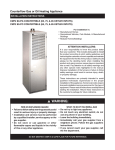
ROYAL OIL 240/320 FURNACE
INSTRUCTIONS
Genisys 7505
Primary Control
Beckett AFG
Oil Burner
Manufacturers of Quality Equipment Since 1910
PO Box 658 303 S. Main St. George, IA. 51237
Phone 888-475-3317 Fax 712-475-3490
www.siebringmfg.com Email [email protected]
1
Table of Contents
Page
Subject
1. Cover
2. Blank
3. Table of Contents
4. Warranty – Condition of Sale
5. New Installations
6. General Chimney Guidelines
7. Why we need Barometric Dampers
8. Draft Regulator Type 34B
9. Draft Regulator Installation
10. Draft Regulator Assembly
11. Main Power Connection
12. Baldor Motor Wiring Schematic
13. Square D breaker box
14. Fan & Limit Control
15. Beckett “CleanCut” Fuel Pump
16. Beckett Burner Wiring
17. Burner Info.
18. Burner Specifications
19. Burner Specifications continued - Primary Control
20. Burner Specifications continued – Ignitor
21. Burner Specifications continued - Cad Cell
22. Burner Specifications continued – Nozzle
23. Burner Specifications continued - Inside your Burner
24. Annual Inspection
25. Troubleshooting – Preliminary Steps, Determining Malfunctions
26. Troubleshooting – Primary Control
27. Troubleshooting – Ignition System
28. Troubleshooting – Burner Motor
29. Troubleshooting – Pump, Nozzle Installation
30. Parts
Included: Beckett AFG Manual, Genisys Quick Reference Guide, and
Honeywell L4064 Fan & Limit Controller pamphlets.
3
CONDITION OF SALE
SIEBRING MANUFACTURING, INC.
GEORGE, IA 51237
Pursuant to Magnuson-Moss Warranty Federal Trade Commission Improvement
Act P.L. 93-637, 88 STAT.2183-2193; U.P.C. 2301-2312 (Jan. 4, 1975), the
following limited warranty will now replace all prior warranties issued by Siebring
Manufacturing, Inc.
We warrant the equipment manufactured by us to be free from defects in material
and workmanship under normal use and service, our obligation under this
warranty being limited to replacing at our factory any product, or parts thereof,
which shall within one year after delivery thereof to the original purchaser be
returned to us with transportation (UPS Ground) charges prepaid, and which our
examination shall disclose to our satisfaction to have been thus defective. We
neither assume nor authorize any other person to assume for us any other liability
in connection with such equipment. “Overnight”, “Next Day” or any shipping
method other than UPS Ground will be the responsibility of the customer. This
warranty shall not apply to any equipment which shall have been repaired or
altered outside of our factory in any way so as to affect its stability and reliability,
nor which has been subject to misuse, negligence or accident, nor to any
equipment, which shall have been operated beyond factory rated capacity. We
shall not be liable for consequential damages caused by defective materials,
equipment or parts warranted by their respective manufacturers.
Any implied warranty (including the warranty of merchantability), to the extent
permitted by law, is excluded.
We will not grant any allowance for any repairs or alterations without written
approval of an executive officer, and we reserve the right to make changes in
design, or to make additions to, or improvements in, our products without
imposing any obligations upon the company to install them on products previously
manufactured.
4
NEW INSTALLATIONS FOR SIEBRING FURNACES
This appliance is manufactured for commercial and industrial use.
This appliance shall be installed in accordance with the standard for the installation of oil
burning equipment. NFPA31 (Latest version)
Uncrate the furnace and block up level. Use nonflammable blocks. Do not rest on flammable
material. Allow 12” on any side and 18” space from the top to any flammable walls or
materials in storage.
Install chimney with the barometric damper. (See picture suggestions page 6) Try to keep
damper in the first 2’ of stack from the furnace. Use a “T” and an elbow for ease of
installation and achieve a -.02” to -.04” water column for the draft.
DO NOT use any method to restrict the draft or reduce the chimney size.
DO NOT restrict the air flow into the blower or the discharge opening.
Hook up the fuel oil system to a #2 heating fuel as shown on the pump label. A two pipe
system is preferable. Be sure to note the insertion of the 1/16” by-pass plug in the pump for
the two pipe set up. (DO NOT attempt to store or use gasoline or other flammable liquids in
this appliance or in the vicinity of the burner. EXPLOSION HAZARD)
Hook up thermostat – Place the thermostat 20’ to 30’ See Beckett AFG manual, page 12, for
oil tank and supply system examples.from the furnace.
- Try to avoid the hot air flow from the furnace on the thermostat.
- Connect thermostat wire to the 24 volt connection of the burner relay marked (T) (T).
(Box on right side of burner, see page 13.)
Connect electrical – Use the adequate size wire (local electrical code) to feed the unit. A test
reading of 115 volts when all the normal electrical demands are on line is required. Use
copper conductors only. Provide a minimum 15A 115V breaker or fuse. DO NOT exceed 25
amps
Consult and use the most recent National Electrical Code (NFPA 70), and meet all local
inspection requirements for installing this heater.
WARNING: DO NOT store or use gasoline or flammable vapors or liquids in the
vicinity of the appliance.
CAUTION: REFRACTORS WILL BE BRITTLE. If a furnace must be moved after being
used for an extended period of time, use a gentle touch when handling the furnace.
5
4
General guidelines for chimneys:
-Each foot of horizontal pipe requires two feet
of vertical pipe.
-Add 2 feet of vertical pipe for each elbow (1).
-Install barometric damper (2) within the first 2
feet of vertical or horizontal (2A) pipe if
possible. Either configuration is acceptable.
Ensure shutter axis of damper is level (3).
-Install a roof cap (4) on top of vertical
chimney.
-Chimney should be 2 feet higher than the
peak of the roof or 10 feet from nearest roof
structure - see inset (5).
1
2A
2
3
5
2’
10’
6
Why we need the Barometric Damper or Draft Regulator on a Furnace
During oil burner operation, combustion air moves into the burner are and combustion
chamber (as combustion air). As combustion continues (the fuel is mixed with air and
burned), a mix of air and combustion gases continues onwards, moving out of the
combustion chamber, up through the furnace heat exchanger, through the flue vent
connector ("stack pipe or flue pipe" ) and on into the chimney where these gases are
finally vented outside, usually above the building roof.
The force with which this air or combustion gas moves is the "draft" inside of the heating
appliance.
Too much draft increases heating appliance operating cost by venting heat out through the
chimney instead of transferring the heat into the building where it was wanted. Too much
draft can also increase chimney temperatures to an unsafe level.
Too little draft can result in incomplete combustion, soot-clogging of heating equipment
(dangerous), and more dangerous heating appliance malfunctions such as oil burner
puffbacks and in some cases dangerous production of carbon monoxide gas that leaks into
the building (a potentially fatal problem).
So virtually all fossil-fuel-fired heating appliances provide some sort of draft control or
draft regulator to keep the draft at required levels both in the combustion chamber and
out through the chimney.
Chimney draft is not constant.
For example wind blowing over a chimney top can increase draft, as can a second
appliance using the same chimney as the heater. Since the force of draft is not normally
constant, and since we want the draft to be constant for optimum oil burner operation,
the barometric damper is installed.
If the oil burner sees flue draft that is too low the combustion gases will not vent safely
out of the building and the heating equipment may suffer from backpressure in the
combustion chamber, causing overheating or other malfunctions.
If the oil burner sees flue draft that is too high combustion gases will vent out of the
building just fine, but we're sending too much heat up the chimney by moving combustion
gases too fast through the heater, thus we're sending our oil dollars up the chimney as
heat rather than into the building as heat.
The service technician adjusts the barometric damper to maintain a continuous draft in
the range we described above. Then if local conditions change, the barometric damper can
open or close to let in more or less additional air into the flue and chimney, keeping the
draft constant.
7
DRAFT REGULATOR (Barometric damper) TYPE 34B
Counter-weight assembly
Threaded nut
attached to vane
Counter balance
weight assembly
Hex lock nut
FIGURE 1
Knurled nut
Vane
Note: Weight assembly must be
attached to vane prior to it’s
installation in the flue pipe.
1. Assemble the "counter balance
weight assembly" to the draft control
as shown.
2. Thread "counter balance weight"
through "threaded nut" attached to
the vane as shown in figure 1.
Thread weight assembly through
vane approximately ⅔ of the way to
allow space to attach the hex and
knurled nut (figure 2).
3. Assemble "hex nut" and "knurled
nut" on front of vane. The knurled
nut is used to adjust the balance
weight and should be tightened on
the threads. The hex nut is used to
secure the weight assembly once the
final adjustments have been made.
4”
MIN.
FIGURE 3
FIGURE 2
Fully assembled
vane/weight assembly
Simplest installation –
insert vane assembly
into 8” pipe Tee
If draft regulator is installed in a pipe “Tee”
instead of using the provided collar halves, the
distance of the collar or the “stub” of the Tee
must be 4” minimum length to avoid the damper
plate entering the flue pipe (see figure 3).
8
DRAFT REGULATOR (Barometric damper) TYPE 34B
Proper operation of the regulator depends on proper installation and adjustment.
Use a CO2 indicator, stack thermometer and draft gauge to adjust to .02 - .04 W.C.
when firing.
FIGURE 4
Best location examples:
(marked in red)
"The control should be located as close as possible to a furnace (figure 4) and
positioned as shown (figure 5). The draft regulator should be 18" from a stack switch
and at least 18" from a combustible ceiling or wall. Do not locate the draft regulator in
a room separated from the appliance."
FIGURE 5
Note: The damper must be mounted so
that the face of the damper is plumb
(figure 6) and the hinge pins horizontal
(figure 7) correct operation.
Hinge pins must be level
FIGURE 6
FIGURE 7
Damper face must be plumb
Note: for additional information, see the Field Controls
Company Installation Instruction Sheet P/N 46001000 Rev. A.
9
Two-piece collar:
-Bend lugs “A” outward @ 90°
-Align holes “B” in the two collar halves and fasten with
three short machine screws and nuts, then tighten.
-Install longer machine screw and nut in lugs “A” but do not
tighten until damper section is in place.
FIGURE 8
Mark thru holes
in tab ends
FIGURE 9
B
A
FIGURE 10
½”
Mark around collar
FIGURE 11
FIGURE 12
-After fabricating collar completely, place tabbed ends against pipe as shown in figure
9, so that the open end of the collar faces outward. Mark thru holes in tabs and drill
or punch holes for sheet metal screws. Note: If holes are drilled about 1/16” toward
back of pipe, this will assure that when the collar is fastened in place, it will be pulled
firmly against the pipe to make a good tight joint.
-After fastening the collar to the pipe, mark around outside of collar (figure 9).
-Remove collar and inscribe a circle ½” inside the one you just marked (figure 10).
-Cut out the inside circle (shaded in blue) to create the opening (figure 10).
-Make a series of slits, cut from the opening outward toward the marked circle to
create tabs (figure 11 & 12).
-Reinstall collar with sheet metal screws and bend newly formed tabs outwards
against the collar to make a tight joint.
-Check damper face for plumb (see figure 6).
-Check hinge pin alignment for level (see figure 7).
10
Royal Oil Main Power Connection
RO240/320
To dedicated
30A service
Typical wiring
2
5
A
!
Fan & Limit
Switch
WARNING: Failure to provide a proper
electrical ground could result in electric
shock or fire.
- Provide furnace with its own separate electrical circuit from the
building’s main breaker panel and a means of circuit protection.
- Wire size to be determined by local code.
11
Baldor Electric Motor Wiring – Low Voltage RO240/320
3
1
2
3
4
5
8
J
2
5
8
J
1
4
LINE
Royal Oil
Wires
Note: Interchange 5 and 8 leads to reverse rotation
Left-hand RO240/320
3
1
2
3
4
5
8
J
2
8
J
1
4
LINE
Royal Oil
Wires
12
5
SQUARE D BREAKER BOX –
RO240/320 Power Hook-up 120VAC
Ground
Common
L1, Line In
Ground
Lug
25
To Burner
Neutral
To Fan
Motor
To Fan &
Limit Switch
13
Fan & Limit Control
Fan Off: 90
Fan On: 110
High limit: 170
To Fan Motor
To Burner
Settings
90 110 170
Hot, connect to
either side
Manual Fan Switch
Brass Jumper
Caution: When adjusting set point levers, hold the scaleplate dial to
keep it from turning and straining the sensing equipment
Cover
Note: For constant fan
operation, push manual fan
switch in. For fan to cycle
automatically, pull button out.
PUSH MAN
PULL AUTO
14
Beckett “CLEANCUT” Fuel Pump – A2EA-6520
NOZZLE PORT 3/16” FLARE FITTING
BYPASS SOLENOID VALVE
CORD SET
BLEED PORT
Beckett
CLEANCUT
INLET PORT ¼
NPTH
RETURN PORT ¼ NPTH (INSTALL 1/16” BYPASS
PIPE PLUG FOR TWO-PIPE SYSTEM ONLY, USE
5/32” ALLEN WRENCH).
Oil Line Hook Up:
-Use two (2) pipe system where possible
-Use only # 2 heating fuel or diesel fuel
-Use individual filter for each unit
-Do not hook multiple units to a single supply line
Prime the Pump
- Bleed air from unit as soon as burner starts rotating.
-To bleed unit, attach a clear plastic hose over bleed
port fitting. Loosen the fitting and catch the oil in an
empty container. Initiate a call for heat. Tighten the
fitting when all air has been purged from the oil
supply system.
Right
side
view
INLET PORT
¼ NPTH
PRESSURE
ADJUSTMENT
SCREW
-If burner locks out on safety during bleeding, reset
the safety switch and complete the bleeding
procedure. (Refer to Honeywell R7184 Primary
control series 5 instructions for special bleeding
procedures, sequences and extended lockout times).
-If burner stops after flame is established, additional
bleeding may be required. Repeat the bleeding
procedure until pump is primed and a flame is
established when the bleeder port is closed.
Observe all local Codes and Regulations for proper set up.
15
4.
1.
1.
2.
6.
2.
3.
10.
7. 8.
5.
9.
Beckett AFG Burner to Furnace Wiring (Genisys 7505)
1.
Two primary control wires (L1 - black & L2 - white) are connected to the
120V power source (blue L1 & white L2). This has the function of
powering the burner, which in turn sends power to the ignitor, burner
motor, solenoid valve and 24V control circuit.
2.
The two yellow wires connect to the cad cell eye and the relay as a “flame
out” safety shutdown after 15 seconds (Genisys 7505).
3.
The 7505 series primary control provides a ¼” quick connect terminal for
all required component wiring:
- Blue or Blue/white stripped wire connects the igniter (6.).
- Orange connects the burner motor (7.).
- L1 black connects power lead (8.).
- 4 neutral positions connect the neutral wire from the igniter, burner motor,
primary control and main burner power (9.).
- Violet/purple connects the fuel solenoid valve (10.).
4.
Flexible conduit from furnace breaker box.
5.
The 2 lower “T T” terminals on the front of the control (see inset) connect
the thermostat.
16
1.
The burner is held in place by three, ⅜” X
16 NC thread studs and nuts.
2.
The white fiber disk is a flame resistant
material and acts as a burner gasket.
3.
Pressure gauge port.
4.
Electrodes and nozzle are accessible by
accomplishing the following steps:
2
1
- loosen the ignitor hold-down clips (4).
- Rotate the ignitor back
- Loosen the copper tube nut (5)
- Remove the splined lock nut (6)
4
6
3
Setting the Electrodes
(See Beckett AFG manual for additional information)
5/32” Gap
Drawing not
to scale
5/16” Above
Center
1/16” Nozzle
to Tip Spacing
17
5
Burner Specifics and Dimensions
The Beckett AFG Oil Burner
The flame retention burner uses # 1 or # 2 heating or
diesel fuel. The flame looks short (12 – 14”) and
medium yellow. The air tube (1.) is 5” for Siebring
products. Pictured are the primary control (2.), the 1/7th
HP motor (3.) and the 20,000 volt ignitor (4.). The
burner has a 15 sec. auto shut down if there is no fuel,
flame or the cad cell eye is dirty.
2
4
1
3
The fuel pump is factory set to 100 PSI. This insures proper atomization of the
fuel. The installed gauge shows the test port location (gauge not included).
2
8
The air shutter should be set on 8 and the air band should be set on 2. The
band adjusts large air amounts and the shutter adjusts small amounts. Smoke
requires more air. Burning eyes and nose from fumes requires less air.
Going into the burner requires loosening of the two screws and moving the
ignitor hold-downs. Lifting the ignitor will expose the oil pipe and electrodes.
The copper tube (⅛”) has a hex flare nut and a splined lock nut (below) for
holding the oil tube in the proper alignment.
Electrodes are to be 1/16” ahead of the nozzle face, and
5/16” above the centerline of the nozzle orifice. See
Beckett AFG manual for proper “F” head adjustments.
The electrodes are to be 5/32” apart. A static plate air restrictor is shown.
The nozzle and nozzle adapter should be tight, but not over tightened. Loosen
the bolt on the electrode clamp to avoid cracking the ceramic insulators when
removing the fuel nozzle
18
Genisys Primary Control
Beckett
MODEL 7505
THERMOSTAT (T W T R)
7505B-1500
Pre
Post
15
0
TW - TR
Lockout
15
Front Decal
IGNITOR (HOT)
IGNITOR (COMMON)
MOTOR (HOT)
MOTOR (COMMON)
LIMIT
L 1 (HOT)
L 2 (COMMON)
VALVE (HOT)
VALVE (COMMON)
CAD
CELL
Reset Button Operation
Flashing = Soft Lockout
Continuous = Hard Lockout
Hold 15 sec to reset from hard lockout
19
Burner Specifics and Dimensions (continued)
The “TW ” and “TR” terminals, normally the
location of the thermostat wires, have a
jumper installed to simulate a call for
heat (Genisys 7505).
The R8184G is installed on some
models. The R8184 does not have the
circuitry for the pump solenoid “valve on”
delay, ignition delay and purge cycle.
Note: When purchasing a replacement primary control, please make note of the model number.
The ignitor transformer springs must contact the electrode rods when the transformer is
in place and secured for operation.
20
Cad Cell Eye Assembly
mounted to the ignitor.
Cad Cell Eye Assembly
removed from the ignitor.
Cad Cell Eye Assembly.
Sensor eye unplugged
from mounting socket.
The cad cell is the sensor that tells the primary control that the fire is burning and the pump
can continue to pump oil. If the surface is over heated or smoked up, a false shut down will
occur after 15 to 45 seconds depending on the factory set lock out time stated on the
primary control. The cell must be in (No Light) before the signal to start the burner is
completed. Trying to start the burner during testing of the ignitor will fail if the eye is seeing
light as it will prevent the burner from starting. Disconnect one yellow lead to the cell to
facilitate testing of the ignitor.
Shock Hazard—Use Insulated Screw Driver
The yellow wire connects to the (F) terminals on the R8184 (gray) series primary control or
the spade connectors marked “CAD CELL” on the bottom of the newer R7184 series
controls. A timer starts when the burner starts and shuts the burner down if no signal passes
the dark cadmium screen. In servicing, care should be taken to remove the 1 terminal wire
to check the primary control shutdown capacity. Overheating during back draft can (destroy)
the eye surface.
21
Burner Specifics and Dimensions (continued)
The transformer or the ignitor can fail any
time from start up, to and thru the useable
life of the heater. Down draft or reverse draft
from exhaust fans operating when the
furnace is hot can ruin the insulation of the
20,000 volt ignitor.
RO240 Nozzle = 1.65 GPH 80°B, RO320 Nozzle = 2.25 GPH 80°B
The nozzle can be disassembled and cleaned by
unscrewing the filter section. A retainer spacer and
the rotor (fine grooves spin the oil) prior to going
out of the orifice as a mist at 100 PSI pressure.
The nozzle body is sized for the proper cone
pattern for the spray and the orifice for the correct
volume of oil at 100 PSI. The pattern is marked
with degrees of spread such as 45 or 80 degrees.
The gallons per hour are marked as .75 or 3.00
and many sizes in between. The correct nozzle
for a RO240 is 1.65 GPH 80°B, the correct nozzle
for the RO320 is 2.25 GPH 80°B.
Typical Oil Burner Nozzle
22
F
H
B
A
C
D
E
A. The fuel pump is made for #2 heating fuel. Waste oil and other contaminates such as
water can ruin the pump. B. The coupling is plastic and can be ruined by reverse drafts,
sucking heat back through burner. C. Air guide directs the combustion air from the blower
wheel D. into the blower. The air shutter controls the quality of the flame and the efficiency
of the burner (shown on page 12) E. The burner motor is 1/7th HP, and turns at 3450 rpm.
There is a thermal reset on some models. If motor over heats after cooling, depress the red
reset button to restart. Two bolts mount the motor to the burner housing.
The fuel pumps are single stage. The A in the serial number
is for single stage and B for two stage. This designates the
vacuum lift for fuel pumping capacity, B having two gears for
high lifts of fuel (see instructions).
The solenoid valve F. delays oil flow 15 sec. till spark is
established.
Two pipe systems require a special set screw (by-pass plug)
furnished for continuous fuel flow. This eliminates air
pockets in the fuel line. The plug for removal to install the set
screw is on the under side of the pump. See diagram on
page 9 and the instructions on the white pump label. The
pump has a strainer G. that should be cleaned periodically.
Access the strainer by removing 4 hex drive screws H. for
the pump cover.
A2EA-6520
G
B
Pump couplings B. join the motor and fuel pump as a common drive for the blower and
pump. The couplings are made of plastic and heat will damage the body of the coupling
when down drafts occur. The end for the pump is smaller and larger for the motor. The
correct length for each pump manufacturer is different but can be cut to length.
Deformed couplings fold up and cause burner failure. Exhaust fans in a room are the
biggest cause of the back flow of heat in greenhouses. The air guide C. is a source of
problem when the reverse draft causes it to be deformed and rub on the blower wheel.
Failure to replace a deformed air guide will cause flame and combustion problems when
the unit is not in place. Please replace deformed parts.
23
ANNUAL INSPECTION
Clean or change nozzle. (Replace with manufacturers recommended size) DO NOT OVER
FIRE!
COMBUSTION TESTS
Draft .02 - .04 inches of water column
Carbon Dioxide (CO2 should be between 10% & 13%)
Smoke Reading #2 - #3 for old units & #0 - #1 for new units
CAD CELL
Flame Detector should read below 1600 Ohms
FUEL FILTER CARTRIDGE – Change or clean
TRANSFORMER
¾ -inch spark jump – 14,000 volts. USE INSULATED SCREWDRIVER TO TEST.
PUMP PRESSURE – Should be 100 lbs. to 110 lbs.
NOZZLE AND ELECTRODES SETTINGS
Beckett: 1/16” in front of nozzle tip
5/32” gap
5/16” above the center of the nozzle
5/16” back from the flame cone
HEAT CIRCULATION SYSTEM
Fan & Limit Switch – 90°, 110°and 170°F. respectively
Belt ½” to ¾” play at mid point
Oil motor bearings lightly 1-2 drops
Oil blower bearings
OIL SUPPLY
Drain off any water
Check pipes for leaks
Check thermostat points – there should be a “click” when calling for heat.
Check the general setup of the furnace to make sure there is make-up air for the burner.
If any ventilation systems were installed, check for NEGATIVE PRESSURE which may have
occurred as a result inside the house. This may cause the chimney to not work properly.
Check the chimney for proper barometric (draft control) free movement.
Roof caps, which do not create vacuum or let in weather are a must.
Follow the recommended chimney set up from this manual to avoid water and condensation
problems.
24
BASIC TROUBLESHOOTING
Recommended Equipment
1.
Electrical test meter (VOLTS, OHMS, AMPS).
2.
Ignition transformer tester
3.
Combustion analyzer kit (oxygen or carbon dioxide, smoke, stack temperature, draft,
system efficiency).
4.
Pressure/vacuum gauge (0-200 psig and 0-30: Hg).
5.
Full assortment of standard hand tools.
Preliminary Steps
1.
Check oil level in supply tank.
2.
Make sure all oil line valves are open.
3.
Examine combustion chamber for excessive unburned oil. Clean if necessary.
4.
Measure line voltage at primary control input connections. It should be 120 volts.
Lower than 105 volts AC may cause operating problems. If there is no reading, check
for open switches or circuit breakers.
5.
Make sure thermostat or other controlling device is calling for burner operation.
6.
Check primary control to see if safety reset switch is “locked out.”
Determining Malfunction Causes
1.
Disconnect nozzle line connector tube and reposition it so that it will deliver oil into a
container. Tighten flare nut at pump discharge fitting.
2.
Reset primary control safety switch if it is locked out. Turn power ON. Observe the
following:
-Contact action of primary relay control. Does it pull in promptly, without arcing
erratically or chattering?
-Oil Delivery. You should have an immediate, clear, steady stream. White frothy oil
means air in the supply system, which must be corrected. No delivery means severe
restriction somewhere.
-Ignition arc. You should hear ignition arc buzzing. If not, test output voltage of
transformer. If below 9,000 volts, replace.
-Motor. Does it pull up quickly and smoothly? Listen for RPM change and audible
“click” as the centrifugal switch disconnects start (auxiliary) winding.
25
If cause of failure has not been identified:
-Reconnect nozzle line fittings for burner fire test.
-Reset primary control if necessary. Run several cycles. Observe flame quality. Use a flame
mirror, if possible, to see if flame base is stable and close to combustion head. Is flame
centered, uniform in shape, and relatively quiet? Are head and chamber free of carbon
formations or impingement? Sometimes a defective or partially plugged nozzle can cause
trouble.
Additional Procedures:
If the problem still has not been identified, a more thorough evaluation of the basic system
must be made. The following procedures may be helpful:
Primary Control System (Cad Cell Type) starts burner, supervises operating cycles, shuts
burner off at end of heat call, and locks out ON SAFETY if there is a flame failure.
1.
Measure electrical voltage at primary input (usually black) and neutral lead (usually
white) connections. It should be 120 volts.
2.
Jumper thermostat (TT terminals) or otherwise energize primary control.
3.
Control relay should pull in. If not, make sure wiring connections are secure and cad
cell is not “seeing” stray light (chamber glow).
4.
If relay pulls in, but motor fails to start, measure voltage between neutral lead (usually
white) and primary control lead for motor (usually orange). Relay switch contacts may
be defective, causing a severe voltage drop.
5.
If relay fails to pull in, or is erratic and chatters, even when wiring connections are
secure, replace control.
6.
Check safety lockout timing by removing one F (cad cell) lead from control. Start
burner and count seconds until control locks out. Time should be reasonably close to
rating plate specifications on primary control body.
7.
To check cad cell, start burner and unhook both cad cell leads from control FF
terminals. Jumper FF screw terminals to keep burner operating. Measure OHMS
resistance across cad cell leads as it views the flame. It should be 1600 OHMS or
less. Preferred reading is 300-1000 OHMS. Next, with meter connected to cad cell
leads, turn burner OFF. DARK conditions should give a reading of 100,000 OHMS or
infinity. If reading is lower, let refractory cool down, and check for stray light entering
burner through air inlet, or around transformer base-plate. If cad cell is not performing
within these guidelines, replace it.
26
8.
The control may be governed by a room thermostat. Be sure heat anticipator setting or
rating of the thermostat matches the 24 volt current draw. This information is usually
printed on the control body. Erratic operation may be caused by improper anticipator
settings. Settings are typically .2 or .4 amps. This value can usually be measured by
connecting a multitester in SERIES with one of the TT leads, and reading the value on
the appropriate milliampere scale.
The Ignition System is generally comprised of an ignition transformer and two electrodes
that deliver a concentrated spark across a fixed gap to ignite oil droplets in the nozzle
spray. Delays in establishing spark at the beginning of the burner cycle can result in
“puff backs,” which can fill the room with fumes. If spark is inadequate, burner may lock
out on safety. If transformer is suspect, make the following checks:
1.
2.
Measure voltage between
transformer/primary lead and neutral
connection. It should be 120 volts on the
primary input side.
Secondary terminals of a good
transformer deliver 10,000 volts each to
ground, for a total of 20,000 volts
between the terminals. Measure this
with a transformer tester or use a wellinsulated screwdriver to draw an arc
across the two springs. This should be
at least 3/4" in length. Check each
secondary output terminal by drawing a
strong arc between the spring and base.
If arc is erratic, weak, or unbalanced
between the two terminals, replace
transformer.
¾”
20,000
Volts
3. Transformer failures and ignition problems can be caused by the following:
-
An excessive gap setting on ignition electrodes will cause higher than normal stress
on the internal insulation system. This can lead to premature failure. Set electrode
gap according to manufacturer’s instructions (typically 5/32”). See diagram on page
12 and the Beckett AFG Burner manual.
-
High ambient temperatures can lower effectiveness of internal insulation system.
-
High humidity conditions can cause over-the-surface arc tracking, both internally and
externally, on ceramic bushings.
-
Carbon residue and other foreign materials adhering to porcelain bushings can
contribute to arc tracking and subsequent failure.
27
-Low input line voltage can cause reduced transformer life. It should be at least 105 volts
AC.
-Electrode insulating porcelains must be clean and free of carbon residue, moisture, crazing,
or pin hole leaks. Leakage paths can contribute to faulty ignition.
-Electrode settings must conform to specifications for gap width, distance in front of nozzle
face, and distance above the nozzle center line. Improper positioning can produce delayed
ignition, spray impingement on electrodes, carbon bridging, and loss of ignition, which can
lead to safety lockouts.
-Replace electrodes if tips are worn or eroded. Replace questionable porcelain insulators.
The Burner Motor drives the blower wheel and fuel pump by means of a shaft coupling. To
diagnose motor problems, follow these guidelines:
1. Motor fails to start.
-Check for adequate voltage between motor/primary lead and neutral connection with the
motor energized. Line voltage must be within 10% of motor rating plate specified voltage.
-If motor hums when energized, but shaft does not rotate, the start switch may be defective.
With the power turned OFF, rotate blower wheel by hand. If it turns freely, replace motor.
-If blower does not turn freely, check for a bound fuel unit, jammed blower, dry bearings, or a
grossly misaligned shaft coupling. Oil bearings with SAE 20W oil. Or, if permanently
lubricated, does not need to be oiled.
2. Other motor-related problems.
-If overload protection has tripped, start motor and measure current draw. It should not
exceed rating plate specifications under load conditions by more than 10%. Excessive amp
draw usually indicates an overload condition, defective start switch, or shorted windings.
-If motor is noisy, check alignment of shaft with coupling. Tighten or slightly loosen motor-toburner-housing bolts in an alternate sequence. Check for loose blower wheel, excessive
radial shaft play or loose start switch parts.
-It is difficult, and usually not cost effective, to rebuild motors in the field. Replace them,
instead.
-If motor operates normally, but does not drive pump shaft, check coupling for slippage due
to stripped end caps.
28
The Fuel Pump transfers oil from the supply tank, cleans it with a strainer or similar
mechanism, pressurizes the oil for good atomization at the nozzle, and provides a good
shutoff at the end of the run cycle. Manufacturers provide excellent installation and service
information. Please read and follow it carefully. Many burner problems can be traced to
incorrect installation of oil piping and fittings.
Nozzles
Oil burner nozzles come in a wide range of designs and sizes. It is essential that the correct
nozzle be used in each installation to assure compatibility with the burner and produce the
desired spray pattern for the appliance in which the burner is used.
When replacing nozzles, it is usually best to use a nozzle identical to the one supplied as
original equipment by the manufacturer. Consult Siebring Manufacturing for specifications
on your furnace whenever possible. Do not assume the nozzle currently in use is the
correct one. It may have been installed in error during a prior burner servicing.
Proper Nozzle Installation
1.
Make sure the fuel supply is clean and free of air or bubbles.
2.
Make sure the pump pressure is set properly, 100 – 120 PSI.
3.
Inspect the nozzle adapter before installing the nozzle. If there are deep groves cut
into it from over tightening, replace it. Those grooves or a scratched surface, may
cause leaks.
4.
When installing the nozzle, use extreme care to protect the nozzle orifice and strainer.
If the orifice gets dirt in it, or becomes scratched, it will not function properly.
5.
Do not over tighten the nozzle when installing. Excessive tightening can cut grooves
into the adapter and cause leaks when the next nozzle is installed.
29
Royal Oil Parts
1
2
2
3
7
4
5
6
9
8
6
10
* DO NOT replace fan
motor with farm duty
or manual reset model
11
1.
Drive Pulley (4 ½” Ø 240, 3 ¾” Ø 320)
2.
Blower motor * ( ¾ HP for 240, 1 HP for 320)
3.
Belt guard
4.
Blower (driven) pulley – 9”
5.
Blower drive belt (47” for 240, 49” for 320)
6.
Blower guard
7.
Breaker box
8.
25A breaker
9.
Fan & Limit switch
Note: Check out our site for commonly
used parts: www.siebringmfg.com
10. Inspection door
11. Beckett AFG burner (see AFG Burner manual)
30