1
SUPER
M35S and M35T1
Mobile Rack
USER'S GUIDE
Rev. 1.0a
®
M35S and M35T1 Mobile Rack User's Guide
The information in this User’s Manual has been carefully reviewed and is believed to be accurate.
The vendor assumes no responsibility for any inaccuracies that may be contained in this document,
makes no commitment to update or to keep current the information in this manual, or to notify any
person or organization of the updates. Please Note: For the most up-to-date version of this
manual, please see our web site at www.supermicro.com.
Super Micro Computer, Inc. ("Supermicro") reserves the right to make changes to the product
described in this manual at any time and without notice. This product, including software and
documentation, is the property of Supermicro and/or its licensors, and is supplied only under a
license. Any use or reproduction of this product is not allowed, except as expressly permitted by
the terms of said license.
IN NO EVENT WILL SUPERMICRO BE LIABLE FOR DIRECT, INDIRECT, SPECIAL, INCIDENTAL,
SPECULATIVE OR CONSEQUENTIAL DAMAGES ARISING FROM THE USE OR INABILITY TO
USE THIS PRODUCT OR DOCUMENTATION, EVEN IF ADVISED OF THE POSSIBILITY OF
SUCH DAMAGES. IN PARTICULAR, SUPERMICRO SHALL NOT HAVE LIABILITY FOR ANY
HARDWARE, SOFTWARE, OR DATA STORED OR USED WITH THE PRODUCT, INCLUDING THE
COSTS OF REPAIRING, REPLACING, INTEGRATING, INSTALLING OR RECOVERING SUCH
HARDWARE, SOFTWARE, OR DATA.
Any disputes arising between manufacturer and customer shall be governed by the laws of Santa
Clara County in the State of California, USA. The State of California, County of Santa Clara shall
be the exclusive venue for the resolution of any such disputes. Super Micro's total liability for all
claims will not exceed the price paid for the hardware product.
California Best Management Practices Regulations for Perchlorate Materials: This Perchlorate
warning applies only to products containing CR (Manganese Dioxide) Lithium coin cells. “Perchlorate
Material-special handling may apply. See www.dtsc.ca.gov/hazardouswaste/perchlorate”
WARNING: Handling of lead solder materials used in this
product may expose you to lead, a chemical known to
the State of California to cause birth defects and other
reproductive harm.
Manual Revision 1.0a
Release Date: August 6, 2010
Unless you request and receive written permission from Super Micro Computer, Inc., you may not
copy any part of this document.
Information in this document is subject to change without notice. Other products and companies
referred to herein are trademarks or registered trademarks of their respective companies or mark
holders.
Copyright © 2010 by Super Micro Computer, Inc.
All rights reserved.
Printed in the United States of America
ii
Safety Information and Technical Specifications
Table of Contents
Chapter 1 Introduction
1-1
Overview ......................................................................................................... 1-1
1-2
Product Features ........................................................................................... 1-1
Operating Systems Supported ........................................................................ 1-1
System Monitoring .......................................................................................... 1-2
1-3
An Important Note to the User ........................................................................ 1-2
1-4
Contacting Supermicro .................................................................................... 1-3
1-5
Returning Merchandise for Service................................................................. 1-4
Chapter 2 SATA-M35 and SCA-M942 Backplane Specifications
2-1
ESD Safety Guidelines ................................................................................... 2-1
2-2
General Safety Guidelines .............................................................................. 2-1
2-3
Introduction to SATA-M35 and SCA-M942 ..................................................... 2-2
Chapter 3 Backplane Connectors, Jumpers and LEDs
3-1
SATA-M35S Front Connectors and Jumpers .................................................. 3-1
3-2
Front Connectors and Pin Definitions ............................................................. 3-2
3-3
SATA-M35S Front Jumpers and Pin Definitions ............................................. 3-3
Explanation of Jumpers .................................................................................. 3-4
3-4
SCA-M942 Front Connectors and Jumpers.................................................... 3-5
3-5
SCA-M942 Front Connectors and Pin Definitions .......................................... 3-6
3-6
SCA-M942 Front Jumpers and Pin Definitions ............................................... 3-7
Explanation of Jumpers .................................................................................. 3-8
Chapter 4 Mobile Rack Installation Procedures
4-1
Tools Required ................................................................................................ 4-1
4-2
Important Safety Guidelines ............................................................................ 4-1
4-3
Installation Procedures .................................................................................... 4-2
Removing Hard Drive Carriers from the Mobile Rack .................................... 4-2
Installing Hard Drives into the Hard Drive Carriers ........................................ 4-4
Additional Optional Installation Information..................................................... 4-9
iii
M35S and M35T1 Mobile Rack User's Guide
Notes
iv
Safety Information and Technical Specifications
Chapter 1
Introduction
1-1
Overview
This manual is written for system integrators, PC technicians and knowledgeable PC
users who intend to integrate Supermicro's intelligent, highly expandable and costeffective mobile rack solutions into their systems. It provides the user with detailed
information for the installation and use of the M35S/M35T1 mobile rack.
The Supermicro M35S/M35T1 mobile rack Supermicro’s CSE-M35S/CSE-M35T1
mobile rack series offers the cutting edge technology with greater flexibility. The
CSE-M35T1 supports five Serial ATA hot-swappable hard drives that yield an unparalleled storage capacity without compromising productivity by eliminating possible
system downtime. The CSE-M35S accommodates five SCSI SCA 320/160 hard
drives which provide configuration flexibility and maximum data integrity.
1-2
Product Features
The M35S/M35T1 mobile rack includes the following features:
•
Supports SCSI or SATA
•
Supports five 3.5" hot-swappable HDDs or three 5.25" HDDs
Operating Systems Supported
For the most up-to-date information visit the Supermicro Web site at www.supermicro.com
•
Windows 2000, Windows XP, and Windows 2003
•
Linux: Red Hat and SuSE
1-1
M35S and M35T1 Mobile Rack User's Guide
System Monitoring
•
Fan failure LED
•
Overheat LED indicatior
•
Drive activity indicatior
1-3
An Important Note to the User
The pictures or graphics shown in this User's Guide were based upon the latest
PCB revision available at the time of the publishing of this manual. The M35S/
M35T1 mobile rack you've received may or may not look exactly the same as the
graphics shown in this manual.
1-2
Safety Information and Technical Specifications
1-4
Contacting Supermicro
Headquarters
Address:
Super Micro Computer, Inc.
980 Rock Ave.
San Jose, CA 95131 U.S.A.
Tel:
+1 (408) 503-8000
Fax:
+1 (408) 503-8008
Email:
[email protected] (General Information)
[email protected] (Technical Support)
Web Site:
www.supermicro.com
Europe
Address:
Super Micro Computer B.V.
Het Sterrenbeeld 28, 5215 ML
's-Hertogenbosch, The Netherlands
Tel:
+31 (0) 73-6400390
Fax:
+31 (0) 73-6416525
Email:
[email protected] (General Information)
[email protected] (Technical Support)
[email protected] (Customer Support)
Asia-Pacific
Address:
Super Micro Computer, Inc.
4F, No. 232-1, Liancheng Rd.
Chung-Ho 235, Taipei County
Taiwan, R.O.C.
Tel:
+886-(2) 8226-3990
Fax:
+886-(2) 8226-3991
Web Site:
www.supermicro.com.tw
Technical Support:
Email:
[email protected]
Tel:
886-2-8226-1900
1-3
M35S and M35T1 Mobile Rack User's Guide
1-5
Returning Merchandise for Service
A receipt or copy of your invoice marked with the date of purchase is required before any warranty service will be rendered. You can obtain service by calling your
vendor for a Returned Merchandise Authorization (RMA) number. When returning
to the manufacturer, the RMA number should be prominently displayed on the
outside of the shipping carton, and mailed prepaid or hand-carried. Shipping and
handling charges will be applied for all orders that must be mailed when service
is complete.
For faster service, RMA authorizations may be requested online (http://www.supermicro.com/support/rma/).
Whenever possible, repack the mobile rack in the original Supermicro carton, using
the original packaging material. If these are no longer available, be sure to pack the
mobile rack securely, using packaging material to surround the mobile rack so that
it does not shift within the carton and become damaged during shipping.
This warranty only covers normal consumer use and does not cover damages incurred in shipping or from failure due to the alteration, misuse, abuse or improper
maintenance of products.
During the warranty period, contact your distributor first for any product problems.
1-4
Safety Information and Technical Specifications
Chapter 2
SATA-M35 and SCA-M942 Backplane Specifications
To avoid personal injury and property damage, carefully follow all the safety steps
listed below when accessing your system or handling the components.
2-1
ESD Safety Guidelines
Electrostatic Discharge (ESD) can damage electronic components. To prevent damage to your system, it is important to handle it very carefully. The following measures
are generally sufficient to protect your equipment from ESD.
•
Use a grounded wrist strap designed to prevent static discharge.
•
Touch a grounded metal object before removing a component from the antistatic
bag.
•
Handle the backplane by its edges only; do not touch its components, peripheral
chips, memory modules or gold contacts.
•
When handling chips or modules, avoid touching their pins.
•
Put the backplane and peripherals back into their antistatic bags when not in
use.
2-2
•
General Safety Guidelines
Always disconnect power cables before installing or removing any components
from the computer, including the mobile rack.
•
Disconnect the power cable before installing or removing any cables from the
mobile rack.
•
Make sure that the mobile rack is securely and properly installed on the motherboard to prevent damage to the system due to power shortage.
2-1
M35S and M35T1 Mobile Rack User's Guide
2-3
Introduction to SATA-M35 and SCA-M942
The M35S and M35T1 mobile racks include either a SATA or SCSI backplane. The
M35S model comes equipped with an SCA-M942 SCSI backplane and the M35T1
comes equipped with a SATA-M35 Serial ATA (SATA) backplane. These backplanes
are designed to utilize the most up-to-date technology available, providing your
system with reliable, high-quality performance.
This manual reflects models SATA-M35 Revision 1.01 and SCA-M942 Revision
1.00, the most current release available at the time of publication. Always refer to
the Supermicro Web site at www.supermicro.com for the latest updates, compatible
parts and supported configurations.
2-2
Safety Information and Technical Specifications
Chapter 3
Backplane Connectors, Jumpers and LEDs
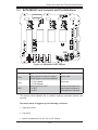
3-1
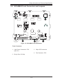
SATA-M35S Front Connectors and Jumpers
1
1
12
14
15
16
17
18
13
Figure 3-1: SATA-M35S Front Connectors
Front Connectors
1. 4-pin Power Connectors: JP10
and JP13
5. SATA Port #2 (Channel 2): J6
6. SATA Port #3 (Channel 3): J7
2. ACT IN: JP26
7. SATA Port #4 (Channel 4): J8
3. Fan Connector: JP22
8. SATA Port #5 (Channel 5): J10
4. SATA Port #1 (Channel 1): J5
3-1
M35S and M35T1 Mobile Rack User's Guide
3-2
Front Connectors and Pin Definitions
1. Mobile Rack Main Power Connectors
Mobile rack
Main Power
4-Pin Connector
The 4-pin power connectors provide power to
the mobile rack. See the table on the right for
Pin#
pin definitions.
1
+12V
2 and 3
Ground
4
+5V
2. Activity LED Connector
Definition
Activity LED Connector
The activity LED connector, designated
JP26, is used to indicate the activity status
of each hard drive. For the activity LED
header to work properly, connect a SATA
LED cable.
Pin#
Definition
Act1/LED1
Channel 1
Act2/LED2
Channel 2
Act3/LED3
Channel 3
Act4/LED4
Channel 4
Act5/LED5
Channel 5
Fan Connectors
3. Fan Connector
The 3-pin connectors, designated JP22,
provides power to the mobile rack fan. See
the table on the right for pin definitions.
4. - 8. SATA Ports
The SATA ports are used to connect the
SATA drive cables. The five ports are designated Channel #1 - #4.
3-2
Pin#
Definition
1
Ground
2
+12V
3
Tachometer
Safety Information and Technical Specifications
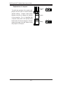
3-3
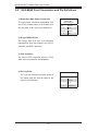
SATA-M35S Front Jumpers and Pin Definitions
JP25
JP18
JP28
Figure 3-2: SATA-M35S Front Jumpers
Jumper Settings
Jumper
Jumper Settings
Note
JP18
Open (jumper off): Buzzer enabled
Closed (jumper on): Buzzer disabled
Buzzer reset*
JP28
1-2: Fan enabled
2-3: Fan disabled
Fan jumper
JP25
Open (jumper off): 45ºC
1-2: 50ºC
2-3: 55ºC
Overheat temperature settings. Buzzer activated at
the temperature indicated.
*The buzzer sound indicates that a condition requiring immediate attention has
occurred.
The buzzer alarm is triggered by the following conditions:
1. Hard drive failure
2. Fan failure
3. System temperature over 45º, 50º or 55º Celsius.
3-3
M35S and M35T1 Mobile Rack User's Guide
Explanation of Jumpers
To modify the operation of the mobile rack,
3
2
1
3
2
1
Connector
Pins
jumpers can be used to choose between
optional settings. Jumpers create shorts
between two pins to change the function
Jumper
of the connector. Pin 1 is identified with
a square solder pad on the printed circuit
board. Note: On two pin jumpers, "Closed"
means the jumper is on and "Open" means
the jumper is off the pins.
3-4
Setting
Safety Information and Technical Specifications
3-4
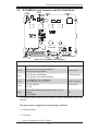
SCA-M942 Front Connectors and Jumpers
14
12
13
1
1
Figure 3-3: SCA-M942 Front Connectors
Front Connectors
1. 4-pin Power Connectors: JP10
and JP13
3. 68-pin SCSI connector
4. Fan Connector: JP22
2. QLogic Gem 318 chip
3-5
M35S and M35T1 Mobile Rack User's Guide
3-5
SCA-M942 Front Connectors and Pin Definitions
1. Mobile Rack Main Power Connectors
The 4-pin power connectors, designated JP10
and JP13, provide power to the mobile rack.
Mobile rack
Main Power
4-Pin Connector
Pin#
See the table on the right for pin definitions.
Definition
1
+12V
2 and 3
4
Ground
+5V
2. QLogic GEM 318 Chip
The QLogic Gem 318 chip is an enclosure
management chip that supports the SES-2
controller and SES-2 protocols.
3. SCSI Connector
The 68-pin SCSI connector allows a SCSI
cable to be connected to the backplane.
4. Fan Connector
Fan Connectors
The 3-pin fan connector provides power to
the mobile rack fan. See the table on the
right for pin definitions.
3-6
Pin#
Definition
1
Ground
2
+12V
3
Tachometer
Safety Information and Technical Specifications
3-6
SCA-M942 Front Jumpers and Pin Definitions
JP21
JP29
JP30
JP18
JP24
Figure 3-4: SCA-M942 Front Jumpers
Jumper Settings
Jumper
Jumper Settings
JP18
Open (jumper off) Disabled (Default)
Close (jumper on) Enabled
JP21
Open (jumper off) Disabled
Close (jumper on) Enabled (Default)
JP24
1-2: SCSI IDs 0,1,2,3,4 (Default)
2-3: SCSI IDs 9, 10, 11, 12, 13
JP29
1-2: ID6 (Default)
2-3: ID8
JP30
1-2: Enabled (Default) Alarm will sound if no fan is
present
2-3: Disabled
Note
Buzzer reset*
SCSI termination
SCSI ID selection
GEM 318 IDs
Fan
*The buzzer sound indicates that a condition requiring immediate attention has
occurred.
The buzzer alarm is triggered by the following conditions:
1. Hard drive failure
2. Fan failure
3. System temperature over 45º Celsius.
3-7
Safety Information and Technical Specifications
Chapter 4
Mobile Rack Installation Procedures
4-1
Tools Required
The following tools are required to install the mobile rack into the chassis:
•
Phillips head screwdriver
•
Antistatic strap (recommended)
4-2
Important Safety Guidelines
This product should be assembled and/or serviced by qualified and experienced
technicians. To avoid personal injury and property damage, carefully follow the
guidelines listed below.
Safety Guidelines
1. Turn off all peripheral devices and the power supply connected to the chassis.
2. Disconnect the chassis from any power source.
3. When disconnecting cables, label them for easy identification.
4. Use a grounded wrist strap designed to prevent static discharge when handling components.
5. Save all the screws and fasteners for later use and label them for easy identification.)
6. Follow the installation procedures in the following section of this manual to
remove and install the hard drives, cooling fan, and the back panel of the
mobile rack.
!
Warning! Enterprise level hard disk drives are recommended
for use in Supermicro chassis and servers. For information on
recommended HDDs, visit the Supermicro Web site at http://
www.supermicro.com/products/nfo/storage.cfm
4-1
M35S and M35T1 Mobile Rack User's Guide
4-3
Installation Procedures
Use the following installation procedures to set up the mobile rack.
!
WARNING!
SAS IDs are assigned automatically by the backplane. Do not
set ID's manually on the drives.
SAS termination is enabled by default on the SAS backplane.
Removing Hard Drive Carriers from the Mobile Rack
The hard drives of the M35S and M35T1 mobile racks are mounted in drive carriers
to simplify their installation and removal from the chassis. These carriers also help
to promote proper airflow within the mobile rack drive bays.
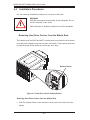
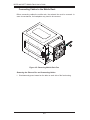
Release Button
Figure 4-1: Hard Drive Carrier Release Button
Removing Hard Drive Carriers from the Mobile Rack
1. Push the release button on the hard drive carrier, which will extend the drive
handle.
4-2
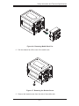
Safety Information and Technical Specifications
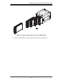
Figure 4-2: Removing Hard Drives From the Mobile Rack
2. Use the drive handle to carefully pull the drive from the mobile rack.
4-3
M35S and M35T1 Mobile Rack User's Guide
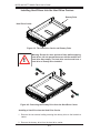
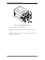
Installing Hard Drives into the Hard Drive Carriers
Dummy Drive
Hard Drive Carrier
Figure 4-3: The Hard Drive Carrier and Dummy Drive
!
Warning: Except for short periods of time while swapping
hard drives, do not operate the server with the mobile rack
hard drive bays empty. The hard drive carrier must have a
hard drive or dummy drive installed.
1
12
1
Figure 4-3: Removing the Dummy Drive from the Hard Drive Carrier
Installing a Hard Drive into the Hard Drive Carrier
1. Remove the two screws holding securing the dummy drive to the hard drive
carrier.
2. Remove the dummy drive from the hard drive carrier.
4-4
Safety Information and Technical Specifications
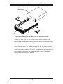
SATA or SCSI
Hard Drive
14
14
Drive Tray
Figure 4-4: Installing the Hard Drive into the Hard Drive Carrier
3. Install a new hard drive into the hard drive carrier with the printed circuit
board side facing downward so that the mounting holes in the hard drive align
with those in the hard drive carrier.
4. Secure the hard drive to the hard drive carrier with the six screws provided.
5. Return the hard drive carrier to the mobile rack. Make sure that the hard drive
carrier handle is returned to the closed and locked position. Repeat these
steps for each hard drive to be installed.
4-5
M35S and M35T1 Mobile Rack User's Guide
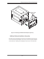
Connecting Cables to the Mobile Rack
Before connecting cables the mobile rack, the exhaust fan must be removed. In
some circumstances, the backplane may need to be removed.
1
1
Figure 4-5: Removing Mobile Rack Fan
Removing the Exhaust Fan and Connecting Cables
1. Simultaneously press inward on the tabs on each side of the fan housing.
4-6
Safety Information and Technical Specifications
12
Figure 4-6: Removing Mobile Rack Fan
2. Pull the exhaust fan off the rear of the mobile rack.
13
Figure 4-7: Removing the Bracket Screw
3. Remove the bracket screw from the side of the mobile rack.
4-7
M35S and M35T1 Mobile Rack User's Guide
14
Figure 4-8: Removing Mobile Rack Bracket
4. Pull the bracket from the rear of the mobile rack.
5. Connect the SATA cables and power cables to the backplane of the mobile
rack.
6. Replace the bracket, bracket screw, and fan on the mobile rack and reconnect power to the chassis.
4-8
Safety Information and Technical Specifications
Backplane Screw
Locations
Figure 4-9: Removing the Mobile Rack Backplane (Optional)
Additional Optional Installation Information
If necessary, before reassembling the mobile rack, the backplane may be removed.
To remove the mobile rack backplane, remove the six screws securing the backplane
to the mobile rack. Carefully pull the backplane from the rear of the mobile rack.
4-9
M35S and M35T1 Mobile Rack User's Guide
Disclaimer (cont.)
The products sold by Supermicro are not intended for and will not be used in life support systems, medical equipment, nuclear facilities or systems, aircraft, aircraft devices,
aircraft/emergency communication devices or other critical systems whose failure to perform be reasonably expected to result in significant injury or loss of life or catastrophic
property damage. Accordingly, Supermicro disclaims any and all liability, and should
buyer use or sell such products for use in such ultra-hazardous applications, it does so
entirely at its own risk. Furthermore, buyer agrees to fully indemnify, defend and hold
Supermicro harmless for and against any and all claims, demands, actions, litigation,
and proceedings of any kind arising out of or related to such ultra-hazardous use or
sale.
4-10