1
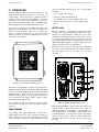
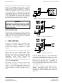
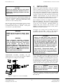
Release 02/2008 Ver. 2.0
5.
Installation Instructions: ZC-Series Controllers
6.
OPERATIONS
SERVICING
TROUBLESHOOTING
CAUTION:
The following steps will usually isolate any problems in a
ZC Series zone controller system:
Be sure the controller has been properly
connected before attempting to operate the
unit.
- De-energize the load until the controller has
been checked out.
BASIC OPERATION
- Check that all wiring is secure and proper.
START UP: Turn on the power. The green power lamp
should light. All red indicator lamps should come on and
remain lit. This indicates that the zones have not been
‘RESET‘. (The AUTO reset version may switch from red
to green).
- Energize the controller only.
Check for
120/240 VAC to ‘HIGH VOLTAGE‘
terminals. Be sure connections are correct!
- Check that a lamp comes on in each zone when
power comes on. If none light, the power
transformer, or rectifier, may be defective, or
there may be loose internal wiring.
MANUAL RESET: Push the red ‘RESET‘ button. All
red and green lamps should come on and remain on until
the button is released. If any lamp does not come on, it
indicates a defective lamp or control channel. If the zone
switches are fault-free, the load contactor will energize with
a sound easily heard outside the cabinet.
- If only a few zones show lights at power on, it
indicates problems in the zones which show no
lamp. The controller’s logic board should be
replaced.
Release the red ‘RESET‘ button. The red lamps will go out
and the green lamps will remain on for all zones with faultfree sensing circuits. If any zone is not clear, its red lamp
will stay lit, and the load contactor will not energize.
- Manual reset only. If, at power on, all lamps
light and the load contactor energizes, it
indicates a short on the ‘RESET‘ lines, which
must be located and corrected! Operation with
a continuously closed ‘RESET‘ circuit will
damage the controller.
DAILY TESTING
Upon startup each day and prior to resetting the controller,
test the lamps, and test each zone by actuating the
appropriate sensing switch. On an AUTO reset model, do
not energize the load until the zones have been tested.
- Check the sensor wiring by pushing and
releasing the ‘RESET‘ button. The red lamps
should all go out, and the load contactors
should energize. If some zones will not reset,
check the sensors on these zones. If necessary,
disconnect sensor wires, and install a known
good FAIL-SAFE four wire switch. If the
zone still fails to ‘RESET‘, it indicates a
defective zone relay, which may be tested by
exchanging controller’s logic boards.
LAMP TEST: Press the red ‘RESET‘ button at any time
to test the lamps. All lamps should light. NOTE: This will
not affect the state of an energized load contactor. (For
auto reset, activate each zone separately to test).
SHUTDOWN
Simply turn off power to the Tapeswitch controller. The
load contactor will de-energize. The load contactor can
also be de-energized by activating one of the zone sensing
switches.
LOCKOUT OR TAGOUT
OSHA regulations (29CFR Part 1910.147). The control of
Hazardous Energy (lockout/tagout) final rule will be
enforced on or after January 2, 1990. This standard
requires employers to develop and utilize an energy control
program to prevent the unexpected energization or start up
of machines and equipment during service and maintenance
operation.
Formal employee training and written
documentation is required. There is no provision for
lockout at this controller.
TAPESWITCH CORPORATION
100 Schmitt Boulevard
Farmingdale, New York 11735
6
Phone: 631-630-0442
Fax: 631-630-0454
www.tapeswitch.com