1
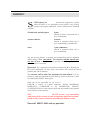
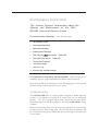
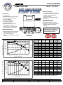
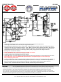
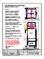
SASE
Bull 300 Vacuum Manual
SASE Company, Inc.
Phone 800.522.2606 or Fax 865.745.4110
www.SASECompany.com
SASE
Corporate Office
26423 79th Ave South
Kent, WA 98032-7321
1.800.522.2606 (P)
1.877.762.0748 (F)
www.SASECompany.com
[email protected]
Congratulations on your decision to get the Power of SASE behind you! SASE is committed to excellence,
excellence in the quality of products we sell and excellence in service and support after the sale. It is important to us that your business continues to succeed and grow, and we know that the right products, service and support can have a great impact on your bottom line.
SASE has made great strides in the concrete preparation and polishing industry over the years. With a
40,000 square foot distribution and service facility in Seattle, a 22,000 square foot distribution and service
facility in Knoxville, and local sales and technical support representatives throughout the United States,
SASE is able to provide unsurpassed service and technical support for the contractor.
At SASE we engineer and manufacture our own equipment, which allows us to be in control of the quality
of the equipment we sell. SASE offers a complete line of concrete preparation and polishing equipment,
our newest introduction being our new line of PDG planetary diamond grinders, which is setting a new
standard for the concrete grinding and polishing industry. SASE is also the leader in diamond tooling technology.
We look forward to a long and prosperous partnership with you! Thank you again for choosing SASE.
You won’t regret having the Power of SASE behind your company!
Sincerely,
SASE Company, Inc.
Jim Weder
President
SASE BULL 300
Series Vacuum System
Operating Instructions
Instructions for Installation, Repair, and Maintenance
CONTENTS
Part 1: Health and Safety
Part 2: Filter Maintenance
Part 3: Ametek Motor
FOREWORD
T
o achieve the safe installation and operation of your new BULL 300
vacuum system, we urge you to become familiar with the information in
this manual.
The SASE BULL 300 industrial vacuum cleaning system is designed for heavy
duty operation. The mechanical and electrical components are of a robust nature
and will provide long life with minimal maintenance even under severe
conditions.
This manual describes the installation and preventative care requirements to
ensure their maximum life and to provide virtually trouble-free operation for
years ahead.
Past experience indicates that the majority of part replacements and repairs
occur due to misuse or carelessness by personnel not qualified to operate
and service this equipment. Observance of the instructions in this manual
will minimize references to those Sections pertaining to Repair and Replacement.
WARRANTY
S
SASE Company, Inc.
warrants this equipment to operate
within the limits of our specification when properly used, properly
operated, and properly maintained. Various subsystems are warranted
as follows:
All metal work excluding paint:
6 years
Limited to failure of structural due to
poor workmanship.
Vacuum Producer :
6 months
Limited to premature failure due to
poor workmanship by manufacturer.
Filters:
2 years (4000 hours)
Limited to premature failure due to
poor workmanship.
Any part proven defective in material and workmanship shall be duplicated
without charge F.O.B. your jobsite. This warranty excludes normal wear
and tear of parts or equipment, and especially excludes degradation from
normal abrasion of corrosion.
Please note! The vacuum producer requires unrestricted air flow! Running the
BULL 300 “deadheaded” for more than a few minutes will overheat the vacuum
producer and void the warranty.
This warranty shall be void if the equipment has been altered or if any
attempt to repair this equipment has been made by persons, institutions or firms
not authorized by SASE to make repairs.
SASE will not be responsible for any costs of
LABOUR to remove or re-install equipment, TOOLS, MATERIALS,
INSURANCE, OVERHEAD or any INCIDENTAL, SPECIAL,
CONSEQUENTIAL or other expenses which may be incurred by the purchaser
in the execution of this warranty.
SASE
will NOT assume any responsibility
under terms of this warranty in parts or equipment which have not been
paid for in full, or where an account is outstanding for 60 days or more.
Please call 800.522.2606
with any questions!
Health and Safety
Recommendations
The Infor mation Contained In This Section
Can Help Prevent Serious Personal Injur y.
PLEASE READ THIS SECTION CAREFULLY
BEFORE OPERATING OR SERVICING THIS
EQUIPMENT.
T
his section outlines s ome of the health and safety issues that must
be acknowledged when operating or servicing your SASE industrial
vacuum cleaning system.
It is important that plant operators are made aware of the responsibility
incumbent on them to take all necessary precautions to ensure their health and
safety, and that plant authorities implement the procedures necessary toward this
end.
We strongly advise that you, the customer, add to, and tailor, these safety
recommendations to suit your own particular working and operating
environment.
Explosive Dust
Please contact us
if your process
changes so we
may help evaluate
your risk.
The operators of this equipment must always be aware of the physical and
chemical properties of the dust particles being collected. A surprising number of
dusts are flammable or prone to explosion when mixed with air as we find with a
filter receiver application.
Materials or processes presenting such hazards MUST be identified by the
customer.
The customer must also be alert to any changes in the dust material or process.
If a new process is introduced after the installation of the vacuum system which
changes the composition, quantity, or most especially the chemical type of
material being introduced into the vacuum system, this may greatly increase the
chance of explosion and fire.
If your process is to be changed, or if you have any concerns, we suggest you
contact us to see how we can assist you to ensure that the operation of your
SASE industrial vacuum cleaning system is as safe as possible.
Isolate Electrical Before Maintenance
Company speci c
lockout and safety
procedures should
be inserted in this
section.
DO NOT ATTEMPT ANY MAINTENANCE WORK UNTIL
ALL ELECTRICAL GEAR HAS BEEN ISOLATED.
Isolate all electrical before removing any guards, covers or accessories before
beginning any maintenance or repair work.
Always lock out the main system blower disconnect before opening any
inspection door on any separator or filter receiver.
Before re-connecting the electrical supply, ensure that all guards, covers and
accessories are correctly replaced.
Implement Measures to Handle Respirable
Dust
Operators must be fitted with appropriate respirators and must wear protective
clothing if handling dust that may be irritating or even toxic.
We recommend that the MSDS’s for each of the dusts to be handled by the
vacuum system be included in this manual, and that specific measures to handle
problem materials be clearly identified in those sections of this manual where the
operator is exposed to these dusts; i.e. filter bag replacement, etc.
Use Suitable Electrical Warning Notices
Do NOT leave electrical gear live and unattended without a suitable warning
notice.
Distinctive warning notices must be provided for posting in a conspicuous
position to any piece of electrical equipment or machinery on which maintenance
is being carried out, and which, for any reason whatsoever, is liable to be left
unattended while in a live condition.
Use CAUTION When Using the Hoses
SASE vacuum systems use blowers that develop very high vacuum conditions
which can be dangerous if caution is not observed.
DO NOT PUT THE END OF THE HOSE AGAINST YOUR
SKIN OR CLOTHES OR THOSE OF OTHERS!
Remove the hose from the inlet valve to dislodge materials that plug the end of
tools.
M aintenance Instructions
This Section Contains Information about the
Upkeep and Maintenance of the SASE
BULL300 Industrial Vacuum System
This section contains information of the following topics:
1.
The Filtration System
2.
Filter Bag Maintenance
3.
Removing Filter Bags
4.
Installing New Filter Bags
5.
Filter Bag Sp
6.
The Inline Filter and Re -Order Info
7.
The Vacuum Producer
8.
The Electric Motor
9.
The Dus t Can
10.
Vacuum Seal Troubleshooting
tion and Re -Order Info
This equipment is designed for full time operation under the most severe
conditions; however, proper maintenance procedures must be observed.
Please read and follow the instructions on the following pages to ensure proper
operation of each of the components of your system.
The Filtration System
The SASE BULL 300 Series of vacuum systems is designed to handle super-fine
powders, so the filtration sub-system is its “heart” and must be maintained
properly. The unit is equipped with fourteen (14) inverted bag type tubular
filters which collect the fine dust particles on the filter’s inside surfaces during
operation.
Before commissioning, remove top motor housing and check to ensure all bags
are firmly secured to the lower bag plate. The top of the bags are attached to the
top of the filter housing by use of bolts and nuts; and the bags must not be loose
or out of place.
NOTE: A loose or unsecured bag will allow product to pass
through the lter separator and will plug t he in-line lter.
The lter bags should be shaken at least daily, preferably after each use. To
shake filter bags, simply shut off the vacuum and shake the filter assembly arm
swiftly back and forth. This rapid movement will dislodge particles on the inside
of the filter bag surfaces and drop them into the dust can.
NOTE: The unit must be OFF in order to shake the lters.
If the filters are to be replaced, please replace them ALL at once, or they will be a
constant source of frustration.
Filter Bag
Maintenance
The following is a recommended program of preventative maintenance:
Operators must be
out tted with
appropriate
respirators and
must wear
protective clothing
if handling dust
that may be
irritating or toxic.
1.
Check that the filters are seated properly and that they do not appear
to be leaking WEEKLY. There should be NO appreciable or
visible dust inside the ter housing .
2.
Replace ALL the filters if wear points or holes are noticed.
3.
If the secondary filter cartridge becomes plugged, check for holes or
leakage in the primary filter bags, or upgrade the primary filter
material to a more efficient type.
4.
Replace the secondary filter cartridge when it becomes dirty.
5.
DO NOT WASH filters. This will destroy the PTFE coating and
cause them to ‘blind’; which will cause the motor to overheat and fail.
Removing Filter Bags
Access the lters by removing the vacuum producer section. To change the
filter bags, unbolt each bag from on the filter shaker assembly inside the tank at
the top.
Squeeze the spring cuff at the bottom of the bag compressing the snap ring into
a “U” shape, and remove from the bag plate hole.
Installing New Filter Bags
The most common
installation
mistake is to
release the cu
lower than it
should be. The
groove in the bag
cu matches the
hole size exactly.
Grasp the spring cuff at the bottom of the bag and compress into a “U” shape.
Insert into the proper hole in the bag plate, and release the bag bottom, assuring
the “groove” in the bag c is centered in the bag plate hole .
Re-bolt to fasten the filters onto the filter shaker assembly.
After installing all the lter s, check the installation from below; all the
lters should be neatly and evenly seated.
WARNING: Failure to assure proper seating of the bag in
the bag plate will allow material leakage.
The Inline Filter
The inline lter supplied with this unit will help prevent damage to the
exhauster in case of failure of a primary filter bags.
become reduced, check that the
Should the air ow of the BULL 300
inline lter has not become blinded by dust, by removing the vacuum
motor housing.
In this situation, inspect the bags for damage, or to see if they have become
loose. Properly clean the bags if no damage is seen.
Remove the inline filter, and clean by back flushing with compressed air (NOT
recommended), or replace the filter.
Restart the unit. If after a short period of time, the inline filter becomes plugged
or blinded, replace the filter bags andthe inline filter element.
Inline cartridge
element re -order
instructions.
PLEASE NOTE!
The vacuum producer requires unrestricted air flow!
Running the BULL 300 “deadheaded” for more than a few minutes will overheat
the vacuum producer and void the warranty.
THIS UNIT IS NOT RECOMMENDED FOR CONNECTION TO A
CENTRAL VACUUM PIPING NETWORK.
Please refer to that section for vacuum producer troubleshooting and
maintenance instructions.
The following sub-sections describe typical maintenance requirements and the
problems that can occur.
The Dust Can
The dust can supplied with this unit is operated by use of two over-center latches.
For proper operation, the dust can must be properly sealed with the filter
housing. When in the latched up position, ensure that the pin of the over-center
latch matches the hooks on the dust can.
Do not over-tighten the latches! Only a moderate pressure is required to form an
airtight seal.
NOTE: Dispose of waste material
environmental codes.
in accordance with local
Vacuum Seals
If you experience a “lack of suction”, almost certainly there is a leak in a seal
somewhere in the system. The following is a short list of common fail points:
1.
Check all gasket seals. If air is leaking in through these seals, dust will
normally collect on the inside surface of the housing showing the exact
location of the leak. Sometimes, running your hands around the door
frame will allow you to locate the leak. Either way, replace the seals as
required.
2.
Especially check the dust can gaskets. If they are torn or worn, please
replace them.
3.
DO NOT over-tighten the lifting mechanism. Almost certainly that will
cause more problems than it fixes. The dust can flange need only
depress the gasket. The seal will form when the system is turned on.
Over-tightening the lifting mechanism will only lead to premature wear
of the gasket and will cause constant problems.
4.
Check the hoses for cracks and leaks. A hose covered in duct tape is a
sure indica tor that the hoses should be replaced.
Product Bulletin
LAMB ELECTRIC
Model: 121118-00
SPECIAL FEATURES
- "Generation II" (DIGITAL) Controller:
no external low-voltage control power
required. (See "INFIN-A-TEK
Application Notes")
- UL component recognized (pending)
- IP Rating: 1.0
- Speed control capability
- High CFM fan system
- Thermally protected motor design
- Aluminum fan end bracket designed to
dampen vibration and improve
durability
DESCRIPTION
- Brushless Motor
- Switch Reluctance (SR) Technology
- One-stage High Flow Fan design
- 120 volts, 50/60 Hz
- 9.1" / 231 mm diameter
- Dual 10mm ball bearings
- Tangential discharge
- All aluminum die cast housings
used in motor construction
- Life expectancy: 5 -10 times more
than the brush-motor equivalent.
Please refer to INFIN-A-TEK
Application Notes for details on
the operation and wiring of this
switched-reluctance motor.
DESIGN APPLICATION
- Equipment operating in environments
requiring separation of working air
from motor ventilating air
- Designed to handle clean, dry, filtered
air only
TYPICAL MOTOR PERFORMANCE.*
80
Flow
250
60
200
50
150
40
30
100
20
50
10
0
2.000
1.750
1.500
1.250
1.125
1.000
0.875
0.750
0.625
0.500
0.375
0.250
0.000
0
Orifice Diameter (Inches)
2000
Flow
100
1600
1400
80
1200
60
1000
800
40
600
400
20
200
Watts
RPM
(In)
Vac
Flow
Air
(In.H2O)
(CFM)
Watts
612
2.000
16.4
1758
20820
21.8
238.4
1.750
16.4
1750
20820
28.4
207.0
692
1.500
16.8
1771
21310
37.1
173.0
754
1.250
15.8
1654
22000
44.8
132.4
697
1.125
14.9
1600
22570
47.8
110.7
622
1.000
14.5
1488
22900
50.1
89.6
528
0.875
13.4
1410
23600
54.5
71.7
459
0.750
12.5
1317
24400
62.3
56.2
411
0.625
12.4
1293
25480
67.5
40.5
321
0.500
11.8
1223
26390
69.5
26.3
215
0.375
11.0
1161
26900
69.6
14.9
122
0.250
11.1
1158
27930
70.4
7.0
58
0.000
10.6
1110
28440
70.1
0.0
0
Orifice
Amps
Watts
RPM
(mm)
Air Flow--L/Sec.
D
A
T
A
120
Vac
1800
Vacuum--MM H20
M
E
T
R
I
C
Amps
(Inches)
Air Flow--CFM
Vacuum--Inches H2O
D
A
T
A
Orifice
300
Vac
70
A
S
T
M
(At 120 volts, 60Hz, test data is corrected to standard conditions of 29.92 Hg, 68° F.)
(In)
Vac
Flow
Air
(mm H2O)
(L/Sec)
Watts
48.0
16.4
1754
20820
627
106.0
647
40.0
16.7
1765
21163
876
86.5
735
30.0
15.3
1624
22314
1180
56.9
656
23.0
13.7
1430
23425
1356
36.0
476
19.0
12.5
1317
24422
1585
26.4
409
16.0
12.4
1294
25437
1709
19.4
325
13.0
11.9
1230
26299
1760
13.1
226
10.0
11.1
1170
26824
1767
7.8
136
6.5
11.0
1158
27879
1787
3.5
61
0.0
10.6
1110
28440
1781
0.0
0
0
0
0.0
6.5
10.0
13.0
16.0
19.0
23.0
30.0
Orifice Diameter (mm)
40.0
48.0
Note: Metric performance data is calculated from the ASTM data above.
* Data represents performance of a typical motor sampled from a large production quantity. Individual motor data may vary due to normal manufacturing variances.
Test Specs: TBD
Minimum Sealed Vacuum: TBD
ORIFICE: 7/8"
Minimum Vacuum: TBD
Maximum Watts: TBD
PRODUCT BULLETIN
121118-00
DIMENSIONS
NOTES
1. Leads: 18ga, stranded power leads; one black and one white, ground lead green with yellow stripe.
Leads: 22ga, control leads: one red, one blue (or orange) and one yellow.
2. Motor Identification: Manufacturer's name, model number, voltage, frequency, inspection code, date of manufacture, agency
recognition code, plant code, "Thermally Protected L 16.0A", "Made in the USA" and the following information: "Manufactured
under patent nos: US5789893, TW81933, SG38957, ZA96/2766, US5760519, EP0702448B1, ZA95/7123 under license from
Switched Reluctance Drive Ltd. Other U.S.and foreign patents pending, copyright code 1998, all rights reserved."
3. Mounting must not restrict this diameter.
4. Allow (0.0026 Sq M) / 4.8" Sq In. (min) for cooling air intake and exhaust.
5. Cooling air intake must be separated from cooling air exhaust.
6. Cooling air exhaust must be separated from vacuum exhaust.
7. Observe NEC wiring convention (black-line and white neutral) to insure proper placement of control module fuse in the circuit.
See wiring options 1 thru 4 of "INFIN-A-TEK Application Notes" for implementing the "control" feature (red,
blue (or orange) & yellow leads).
8. The INFIN-A-TEK blower utilizes a switched reluctance (SR) brushless motor, which is commutated electronically. Similar to a
brush type series universal motor, this INFIN-A-TEK (SR) blower operates on AC voltage. The INFIN-A-TEK (SR) blower
features an integral electronic control module that rectifies the "AC line voltage" to obtain the DC voltage required to
power the motor. All switched reluctance motors are thermally protected using an auto-reset device.
IMPORTANT NOTES:
Pictorial and dimensional data are subject to change without notice. Contact factory for current revision levels.
WARNING
When using AMETEK/Lamb Electric bypass motors in machines that come in contact with foam, liquid (including water)
-
of other foreign substances, the machine must be designed and constructed to prevent those substances from reaching the fan system, motor housing
and electrical components. Lamb vacuum motors other than hazardous duty models should not be applied in machines that come in contact
with dry chemicals or other volatile materials. Failure to observe these precautions could cause flashing (depending on volatility) or electrical shock
which could result in property damage and severe bodily injury, including death in extreme cases. All applications incorporating Lamb motors should be
submitted to appropriate organizations or agencies for testing specifically related to the safety of your equipment.
AMETEK/Lamb Electric Division, 627 Lake Street, Kent, Ohio 44240 U.S.A.
Tel: (330) 673-3451 Fax: (330) 677-3812 Website: www.lambelectric.com
SASE BULL 300
27.00
BLOWER
28.38
SOUND PROOFING
FILTER
SHAKER
SILENCERS
SAFETY
FILTER
HEAVY
DUTY
FRAME
64.37
36.7 SF
PRIMARY
FILTER
3" OD
5"
SASE COMPANY, INC.
KENT, WA 98032 800-522-2606