1
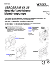
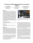
SASE SC10E Scarifier Manual SASE Company, Inc. Phone 800.522.2606 or Fax 877.762.0748 www.SASECompany.com SASE Corporate Office 26423 79th Ave South Kent, WA 98032-7321 1.800.522.2606 (P) 1.877.762.0748 (F) www.SASECompany.com [email protected] Congratulations on your decision to get the Power of SASE behind you! SASE is committed to excellence, excellence in the quality of products we sell and excellence in service and support after the sale. It is important to us that your business continues to succeed and grow, and we know that the right products, service and support can have a great impact on your bottom line. SASE has made great strides in the concrete preparation and polishing industry over the years. With a 40,000 square foot distribution and service facility in Seattle, a 22,000 square foot distribution and service facility in Knoxville, and local sales and technical support representatives throughout the United States, SASE is able to provide unsurpassed service and technical support for the contractor. At SASE we engineer and manufacture our own equipment, which allows us to be in control of the quality of the equipment we sell. SASE offers a complete line of concrete preparation and polishing equipment, our newest introduction being our new line of PDG planetary diamond grinders, which is setting a new standard for the concrete grinding and polishing industry. SASE is also the leader in diamond tooling technology. We look forward to a long and prosperous partnership with you! Thank you again for choosing SASE. You won’t regret having the Power of SASE behind your company! Sincerely, SASE Company, Inc. Jim Weder President SASE Company Inc. Equipment Safety Policy Statement SASE Company, Inc. is adamant that safety is one of the highest priorities for both our employees and customers. When considering set-up and operation of any piece of equipment supplied, manufactured, distributed, rented or serviced by SASE Company, Inc., the safety and protection of people should always be a top priority. All customers and employees should follow all OSHA and local safety standards, requirements and regulations. The use of the following safety equipments are both recommended and required when operating any piece of equipment supplied, manufactured, distributed, rented or serviced by SASE Company, Inc. OSHA approved/certified eye protection (safety glasses). OSHA approved/certified hearing and ear protection. OSHA approved/certified foot protection (steel toed boots). OSHA approved/certified respirator or breathing device. OSHA approved head protection (hard hat). Proper protective work gloves. Proper protective clothing limiting skin exposure. (The list is not meant to be all inclusive. Please exercise sound judgments during operation.) The work area must always have proper ventilation to minimize the health and safety risks of propane and gasoline emissions and airborne dust. All SASE Company Equipment is engineered, designed and provided with dust control shrouds and vacuum ports. It is strongly recommended that an approved dust containment system be connected to and used in conjunction with all SASE Company equipment during operational use. SASE Company supplies, distributes, rents and services dust control systems with HEPA filtration. Extreme caution must be exercised at all times when electrical power is considered. All SASE employees are prohibited from working on or hard wiring our equipments to any power source that has not been provided by SASE Company Inc. Any such work must be performed by a certified electrical technician. No SASE employee is permitted or authorized to work on, operate, or connect our equipment or equipment belonging to our customers to an electrical source that does not meet OSHA approved specifications. There are no exceptions to this policy! SASE Company, Inc. also strongly recommends that only certified electricians be permitted to deal with or manipulate electrical power sources within our customers’ facilities or on their job-sites. Finally, we at SASE Company, Inc. cannot stress enough the importance of following general safety practices, the utilization of appropriate safety equipment and the application of common sense when operating equipment supplied, manufactured, distributed, rented or serviced by SASE Company, Inc. (JJL 07/2010) both on the job-site and in the field. SASE Company, Inc. Scarifier SC10E User Manual Important Information DO NOT OPERATE THIS EQUIPMENT WITHIN AN ENCLOSED AREA. The exhaust from the internal combustion engine contains carbon monoxide, an odorless and deadly poison. If using equipment indoors, proper and adequate ventilation is required. An approved OSHA air-monitoring system must be in place at all times. Avoid inhalation of exhaust gas. Carbon monoxide gas is toxic. Breathing it can cause unconsciousness and may KILL you. Avoid any areas or actions that expose you to carbon monoxide. Do to the use of the equipment; suitable protective clothing must be worn or bodily harm may occur. The machine operator must wear eye protection, gloves, earplugs and non-slip safety shoes. When doing work that causes dust, wear an appropriate respiratory mask that will protect you from the type of dust you are working in. Before operation please read about this topic and other important safety information that is contained within the enclosed Engine Owners Manual. SASE Company, Inc. Scarifier SC10E User Manual ____________________________________________________________________________________________________ READ AND UNDERSTAND BEFORE ATTEMPTING TO OPERATE THIS EQUIPMENT Safety Communication Safety Instructions are preceded by a graphic alert symbol of DANGER, WARNING, or CAUTION Imminent hazard which, if not avoided, will result in death or serious injury. Imminent hazard which, if not avoided, can result in death or serious injury. Hazards which, if not avoided, could result in serious injury and or damage to the equipment. General Instructions Maintain the machine in safe operating condition with all guards in place and secure all mechanical fasteners tight Ensure all controls in working order and the machine is configured for the job application. Be sure all safety decals can be clearly read and understood. Replace damaged or missing decals immediately. Equipment should only be operated by trained personnel in good physical condition and mental health. Never operate this machine while under the influence of drugs, alcohol or when taking medications that impair the senses or reactions, or when excessively tired or under stress. Avoid deck inserts, pipes, columns, openings, electrical outlets, or any objects protruding from slab surface. Maintain a safe operating distance to other personnel. It is the operators’ responsibility to keep other people (workers, pedestrians, bystanders, etc.) at a safe distance during operation. Block off the work area in all directions. Failure to do so may result in others being injured by flying debris or exposing them to harmful dust and noise. For the operator’s safety and the safety of others, always keep all guards in place during operation. Never let equipment run unattended. 7 SASE Company, Inc. Scarifier SC10E User Manual ____________________________________________________________________________________________________ (PPE) Personal Protection Equipment Proper safety attire must be worn when operating this machinery. The operator must wear approved safety equipment appropriate for the job such as hard hat and safety shoes when conditions require. Ear protection must be worn at all times when this machine is in use. During normal use, sound levels exceed 92dB. Eye protection must be worn at all times when this machine is in use. Use only ANSI approved safety glasses to help prevent eye injury. Operator must wear appropriate clothing and footwear. Steel toe safety shoes should be worn. Do not wear loose clothing or jewelry that can get tangled or caught in moving parts. Keep body parts and loose clothing away from moving parts. Failure to do so could result in dismemberment or death. General Operation Stop motor/engine when adjusting or servicing this equipment. Maintain a safe operating distance from flammable materials. Sparks from the cutting-action of this machine can ignite flammable materials or vapors. Check motor rotation. DO NOT use if drum rotation is incorrect - have a qualified electrician make the necessary change in the main control panel or motor connection box. 8 SASE Company, Inc. Scarifier SC10E User Manual ____________________________________________________________________________________________________ Before Starting the Machine Perform a visual inspection of the entire machine and all daily maintenance according to the Maintenance Schedule. Locate and be familiar with all engine/motor and operating controls. For Gasoline models, obtain the Engine Manufacturer’s Owner’s Manual. Read it and understand it before continuing. Follow the engine manual for break-in instructions. Use the correct cutters for the job. Be sure cutter drum is balanced, the number, size and type of cutter wheels are correct. Be sure all fasteners are tight and secure, check for signs of metal cracking or fatigue, inspect for damage to electrical wiring, damage to fuel lines, check bearings, etc. Be sure all guards are in place. Inspect work area to determine the presence and location of deck inserts, pipes, columns and objects protruding from the slab surface so that they may be avoided during operation. Safety warnings and guidelines do not by themselves eliminate danger. They are not given as substitutes for proper accident prevention and good judgment. Electrical Powered Equipment For Electric Models - Electric motors must be properly grounded at all times. Check the outlet box to be sure the electrical service is properly grounded. Be sure adequate power is available. Insufficient power will cause a motor to overheat and burn out. Use only grounded extension cords correctly sized for the current draw and voltage drop (amp rating and length). Never use frayed, damaged, taped or under rated extension cords. Electrical shock could result in death or serious injury to the operator and damage to the equipment. Extreme care must be taken when operating electric models with water present: Ensure power cord is properly grounded, is attached to a Ground-Fault-Interrupter (GFI) outlet, and is undamaged. Check all electrical cables - be sure connections are tight and cable is continuous and in good condition. Be sure cable is correctly rated for both the operating current and voltage of this equipment. Improper connection of the equipment-grounding conductor can result in a risk of electric shock. Check with qualified electrician or service person if there is any doubt as to whether the outlet is properly grounded. Adhere to all local codes and ordinances. 9 SASE Company, Inc. Scarifier SC10E User Manual ____________________________________________________________________________________________________ NOTE: In the event of a malfunction or breakdown, grounding provides a path of least resistance for the electric current to dissipate. The motor is equipped with a grounded plug and must be connected to an outlet that is properly installed and properly grounded. DO NOT modify the plug provided on the motor. If the plug does not fit the outlet have a qualified electrician install the proper receptacle. Switch motor OFF before disconnecting power. Do not disconnect power by pulling cord. To disconnect, grasp the plug, not the cord. Unplug power cord at the machine when not in use and before servicing. Starting the Engine/Motor for Electric Models Be sure the “OFF” button is depressed on the motor starter box. Hook up the correct voltage/phase electrical power source by plugging into the connector provided. If the cord does not mate with the connector, consult a qualified licensed electrician before continuing. Verify that the electrical current being supplied is the proper voltage and phase required to run the equipment. POISONOUS EXHAUST Gasoline Powered Models DO NOT operate any gasoline powered equipment without adequate ventilation. Carbon monoxide is an invisible, odorless gas that can kill. NEVER REFUEL A HOT ENGINE OR AN ENGINE WHILE IT IS RUNNING. Only refuel a cool “stopped” engine in a well-ventilated area. Properly clean any spilled fuel before starting the engine. Gasoline is extremely flammable and poisonous. It should only be dispensed in well ventilated areas, and with a cool engine.. Engine exhaust from this product contains chemicals known to cause cancer, birth defects or other reproductive harm. Small gasoline engines produce high concentrations of carbon monoxide (CO). Gasoline powered equipment should not be used in enclosed or partially enclosed areas. Symptoms of CO poisoning include, headache, nausea, weakness, dizziness, visual problems and loss of consciousness. If symptoms occur get into fresh air and seek medical attention immediately. Gasoline Models - Consult the Engine Manufacturer’s Owner’s Manual and follow the directions for starting the engine and allow the engine to warm up. Refer to the Engine/Motor Manufacturer’s Owner’s Manual for maintenance information specific to the engine/motor used. 10 SASE Company, Inc. Scarifier SC10E User Manual ____________________________________________________________________________________________________ Dust Warning Some dust created by grinding and other construction activities contains chemicals known to cause cancer, birth defects, or other reproductive harm. Some examples of these chemicals are: Lead from lead-based paints Crystalline silica from concrete and other masonry products. Your risk of exposure to these chemicals varies depending on how often you do this type of work. To reduce your risk work in a well ventilated area, use a dust control system, such as an industrial-style vacuum, and wear approved personal safety equipment, such as a dust/particle respirator designed to filter out microscopic particles. Dry Grinding Dry Grinding creates a large volume of airborne dust. For health reasons, the operator should wear an applicable respirator. The dust may contain chemicals known to cause serious illnesses, including Silicosis - a fatal disease of the lungs. Check the chemical properties of the material to be removed and follow all EPA/OSHA regulations. An Industrial vacuum, capable of handling high volume of fine dust, should be used when dry grinding with this machine. If the material being used is hazardous or contains Silica - the vacuum unit should be capable of removing Silica and hazardous particles of less than 3 microns and if necessary, have the capability to be equipped with a HEPA filter. Most standard drum type units use a paper bag filter. The dust created during grinding is extremely fine and will clog the filter bag of these units and eventually damage the vacuums motor. In addition, damage to the engine could occur. The collected debris and filters should be disposed of according to procedures that comply with current EPA/OSHA standards Serious injury or death could occur if this machine is used improperly 11 SASE Company, Inc. Scarifier SC10E User Manual ____________________________________________________________________________________________________ Maintenance Proper belt tension must be maintained to transmit the engine/motor power to the cutting drum. An over tensioned belt will shorten belt and bearing life. A damaged, stretched or excessively worn belt should be replaced. Check oil level before operation. Change engine oil and filter according to engine manufacturers recommendations. Engine Air Filter Important! Clean air filter element daily Inspect the air filter for excess dust, dirt or damage before the engine is operated. More often if operating in an extremely dusty environment. Operating the engine with a damaged or dirty air filter, or without an air filter, will allow dirt to enter the engine causing premature engine wear which is not covered under the engine manufacturer’s warranty. Follow the engine manufacturer’s procedures for keeping filters in good condition. Never work on or under equipment without first securing the equipment to prevent it from moving or falling. Always work on a flat and level surface. Remove spark plug lead on gasoline engine models or disconnect the supply voltage connector on electric models before performing any maintenance. Disconnect the power cord at the machine. 12 Operating Procedures for SC10E (GAS) Start-Up • • • • • • • • • Add oil and gasoline to the machine. Move the fuel valve lever to the ON position. Move the choke lever to the CLOSED position (cold engine). Move the throttle lever 1/3 of the way toward the FAST position. Turn the engine switch to the ON position. Operate the starter by lightly pulling the starter grip until you feel resistance, then pull briskly. Gently return the starter grip. Lower drum and begin grinding. Read the following additional information before operating your scarifier. Caution: Never tilt the unit back on the handle. Oil will flow into the cylinder head and could severely damage the motor and void the warranty. Drive Motor/Engine: The internal combustion engines are supplied without fuel or motor oil. Therefore, be sure to fill them as instructed in the manufacturer’s manual. If the motor suddenly stops, the oil could be to low or it may have been overfilled. Caution: Start the motor ONLY when the cutter drum assembly is in the raised position and the parking brake on. Cutter/Drum Configuration Check to make sure that the drum is configured with the cutters we recommend for the application in question. When working with special milling cutters, be extra careful about the correct direction of drum rotation and correct cutter installation. Never tip the machine on its back to look at the cutters. This can be done quickly and easily by removing the endplate. When putting the endplate back on the machine, make certain to check the tightening torque of cover nuts. Caution: To avoid bearing damage, repeat this check of the cover nuts from time to time! Working with the Scarifier: To engage the drum, lift the black handle up and proceed in forward motion with the lever. Once the drum engages, you can go lower for more aggressive cutting or back up for lighter scarifying. For fine-tuning of the adjustment depth, turn the black dial clockwise until the desired adjustment is reached. Caution: Do not lower the black handle too deep. This will NOT increase productivity. When the depth is set correctly, the machine will run smoothly. To stop scarifying, lift the black handle up and proceed in a backward motion until the lever is in the uppermost position Changing the cutter drum: Always be sure to switch off the machine before removing the endplate. This will prevent any flying debris from injuring the worker. Remove the cover nuts from the endplate, and then remove the endplate to expose the cutter drum assembly. Dust Control: Should dust control be of concern, please contact SASE Company, Inc. to inquire about our powerful dust control vacuums. The SC10E can be used with an optional 2” vacuum connection. If you need further assistance, please call our toll free number 1-800-522-2606. Cutter and Flail Shaft Recommendations - The above flail shafts are showing excessive wear. These shafts should have been replaced much earlier. To a great extent, economical use of cutter drums depends upon proper maintenance. Changing flail shafts before they become excessively worn and begin to oval out the shaft holes can significantly increase the life of the drum. If you run a machine with badly worn flail shafts you can easily destroy a drum in just a few hours. These shafts are only surface hardened in order to maintain their internal strength. This is why it is important to replace them as soon as the grooves are 1/5 of an inch or 5mm deep. Changing the shafts early provides the following advantages: • • The drum shaft holes will not wear as fast thus increasing drum life. Breakage of shafts can be avoided, thus saving a great deal of downtime refitting the machine. Recommendations: • • • When working with five or eight point Tungsten Carbide tipped cutters or special milling cutters, replace the shafts every fifteen to twenty hours of operation. When working with steel cutters change the shafts every time new cutters are installed. Change the entire cutter/drum assembly after 3 sets of cutters have been used up, if not sooner. SASE Company, Inc. 800.522.2606 www.SASECompany.com SC10E Gas 12 2 13 1 Dead Man’s Switch & Wiring 6 8 8 5 10 7 3 21 11 22 SC10E 230V Single Phase 9 12 10 13 Dead Man’s Switch & Wiring 1 4 5 3 6 7 2 33 8 34 SC10E 230V Single Phase SC.10.040 Item No 1 2 3 4 5 6 7 8 9 10 11 12 13 33 34 Part No NB.10.106 NB.10.114 NB.10.130 NB.20.131 NB.30.110 NB.30.111 NB.30.212 NB.30.403 SC.10.000 SC.10.149 SC.10.154 VAC.8A02261 VAC.HS2.00TR7 SC.10.153 SC.10.154 Description SCREW, HEX HEAD M10 X 70 ZINC SCREW, HEX M8 X 20 ZINC SCREW, HEX HEAD M8 X 16 ZINC NUT, NYLOC M10 ZINC WASHER, FLAT M10 ZINC WASHER, FLAT M8 ZINC WASHER, LOCK M8 ZINC WASHER, FENDER M8 X 30 ZINC SCARIFIER, BLACK SC10E CHASSIS W/ DRUM MOTOR, ELECTRIC SINGLE PHASE 220V VA25S PULLEY, UPPER TOOTH ELECTRIC FR250 VA25S CAP, 2 INCH INLET BULL 100 HOSE, VACUUM FOR SC10E 2.0" ID BY THE FOOT BELT, TOOTHED 840 VA25Sn VA25 PULLEY, UPPER TOOTH ELECTRIC FR250 VA25S Dead Man's Switch & Wiring * 795.00.19 Emergency Stop Tether Switch * 795.00.22 22-18 AWG Butt Connector Red Vinyl * 795.00.23 3/8" Black Heat Shrink Tubing * AIW.16X2CRD CORD, POWER 16/2 * 654.21.01 BAR, DISTANCE VA 25 ELECTRIC * 795.00.04 CONDUIT, 3/4" LIQUIDTIGHT FLEXIBLE NON-METALLIC * 795.00.05 3/4" L/T BULLET CONNECTOR LT75P * 795.00.06 3/4" W/R BLACK SLRN21 * 795.00.07 1/2-IN BLACK CORD GRIP SLN13 * 795.00.08 3/4-IN 45 BULLET L/T CONNECTOR * 795.00.10 18 GAUGE WIRE NUT YELLOW * 795.00.12 ZIP TIE BLK 11" X 0.125" * 795.00.19 SWITCH, EMERGENCY STOP TETHER WITH CORD * AIW.10X3CRD CORD, POWER 10/3 * MCC.27.25A SWITCH, 25 AMP * MCC.27.KAZ BOX, SWITCH ENCLOSURE FOR 25A SWITCH * MCC.27AA220 MODULE, SHUNT RELAY 220V FOR 25A SWITCH 1 * NB.19.101 SCREW, PAN HEAD 8 -32 X 3/4 * NB.20.133 NUT, NYLOC 8-32 ZINC Capacitors * MCC.CAP.200 CAPACITOR, START SC10E 230V 1 PHASE * MCC.CAP.210 CAPACITOR, RUN SC10E 220 VOLT 1 PHASE * Orient upper pulley nipple outward the motor * Set to 24 AMP in switch * Cut off excess shaft length, then Drill, then Tap Quantity 4 1 2 4 4 2 2 1 1 1 1 1 2 1 1 1 2 4 in 1 ft 2 4 ft 1 1 1 1 5 4 1 6 ft 1 1 1 2 2 1 2 SC10E 230V Three Phase 8 12 13 Dead Man’s Switch & Wiring 9 1 3 2 5 7 2 10 4 11 6 Item No 1 2 3 4 5 6 7 8 9 10 11 12 13 14 15 16 17 18 19 20 21 22 23 24 25 26 27 28 29 30 31 32 Part No NB.10.110 NB.10.130 NB.30.110 NB.30.111 NB.30.210 NB.30.212 NB.30.403 SC.10.000 SC.10.150 SC.10.153 SC.10.154 VAC.8A02261 VAC.HS2.00TR7 SC10E 230V Three Phase SC.10.042 Description SCREW, HEX M10 X 25 ZINC SCREW, HEX HEAD M8 X 16 ZINC WASHER, FLAT M10 ZINC WASHER, FLAT M8 ZINC WASHER, LOCK M10 ZINC WASHER, LOCK M8 ZINC WASHER, FENDER M8 X 30 ZINC SCARIFIER, BLACK SC10E CHASSIS W/ DRUM MOTOR, ELECTRIC 3 PHASE VA25S SC10E BELT, TOOTH 840 VA25S SC10E ELECTRIC VA25 PULLEY, UPPER TOOTH ELECTRIC FR250 VA25S CAP, 2 INCH INLET BULL 100 HOSE, VACUUM FOR SC10E 2.0" ID BY THE FOOT Dead Man's Switch & Wiring 795.00.19 Emergency Stop Tether Switch 795.00.22 22-18 AWG Butt Connector Red Vinyl 795.00.23 3/8" Black Heat Shrink Tubing AIW.16X2CRD CORD, POWER 16/2 795.00.04 CONDUIT, 3/4" LIQUIDTIGHT FLEXIBLE NON-METALLIC 795.00.05 3/4" L/T BULLET CONNECTOR LT75P 795.00.06 3/4" W/R BLACK SLRN21 795.00.07 1/2-IN BLACK CORD GRIP SLN13 795.00.08 3/4-IN 45 BULLET L/T CONNECTOR 795.00.10 18 GAUGE WIRE NUT YELLOW 795.00.11 20 GAUGE WIRE NUT ORANGE 795.00.12 ZIP TIE BLK 11" X 0.125" 795.00.19 SWITCH, EMERGENCY STOP TETHER WITH CORD AIW.10X4CRD CORD, POWER 10/4 MCC.27.16A SWITCH, 16 AMP MCC.27AA220 MODULE, SHUNT RELAY 220V FOR 25A SWITCH MCC.27.KAZ BOX, SWITCH ENCLOSURE FOR 25A SWITCH NB.19.101 SCREW, PAN HEAD 8 -32 X 3/4 NB.20.133 NUT, NYLOC 8-32 ZINC *Orient upper pulley nipple outward the motor Quantity 4 3 4 2 4 2 1 1 1 1 1 1 2 1 2 4 in 1 ft 3 ft 1 1 1 1 3 3 4 1 6 ft 1 1 1 2 2 SC10E 460V Three Phase 10 11 Dead Man’s Switch & Wiring 7 1 3 4 2 3 4 2 8 5 9 Item No 1 2 3 4 5 6 7 8 9 10 11 12 13 14 15 16 17 18 19 20 21 22 23 24 25 26 27 28 29 30 Part No NB.10.109 NB.10.130 NB.30.111 NB.30.212 NB.30.403 SC.10.000 SC.10.150 SC.10.153 SC.10.154 VAC.8A02261 VAC.HS2.00TR7 SC10E 460V Three Phase SC.10.044 Description SCREW, HEX HEAD M8 X 25 ZINC SCREW, HEX HEAD M8 X 16 ZINC WASHER, FLAT M8 ZINC WASHER, LOCK M8 ZINC WASHER, FENDER M8 X 30 ZINC SCARIFIER, BLACK SC10E CHASSIS W/ DRUM MOTOR, ELECTRIC 3 PHASE VA25S SC10E BELT, TOOTH 840 VA25S SC10E ELECTRIC VA25 PULLEY, UPPER TOOTH ELECTRIC FR250 VA25S CAP, 2 INCH INLET BULL 100 HOSE, VACUUM FOR SC10E 2.0" ID BY THE FOOT Dead Man's Switch & Wiring 795.00.19 Emergency Stop Tether Switch 795.00.22 22-18 AWG Butt Connector Red Vinyl 795.00.23 3/8" Black Heat Shrink Tubing AIW.16X2CRD CORD, POWER 16/2 795.00.04 CONDUIT, 3/4" LIQUIDTIGHT FLEXIBLE NON-METALLIC 795.00.05 3/4" L/T BULLET CONNECTOR LT75P 795.00.06 3/4" W/R BLACK SLRN21 795.00.07 1/2-IN BLACK CORD GRIP SLN13 795.00.08 3/4-IN 45 BULLET L/T CONNECTOR 795.00.10 18 GAUGE WIRE NUT YELLOW 795.00.11 20 GAUGE WIRE NUT ORANGE 795.00.12 ZIP TIE BLK 11" X 0.125" 795.00.19 SWITCH, EMERGENCY STOP TETHER WITH CORD AIW.10X4CRD CORD, POWER 10/4 MCC.27.10A SWITCH, 10 AMP MCC.27AA440 MODULE, SHUNT RELAY 440V MCC.27.KAZ BOX, SWITCH ENCLOSURE FOR 25A SWITCH NB.19.101 SCREW, PAN HEAD 8 -32 X 3/4 NB.20.133 NUT, NYLOC 8-32 ZINC *Orient upper pulley nipple outward the motor *8 Amp Quantity 4 3 6 6 1 1 1 1 1 1 2 ft 1 2 4 in 1 ft 3 ft 1 1 1 1 3 3 4 1 6 ft 1 1 1 2 2 Parts for Tensioning Pulley; Belt Guard List of Items for Tensioning Pulley; Belt Guard Number Quantity Part Number Description 1 SC.10.121 PULLEY, TENSIONING 1 2 SC.10.122 SPACER, TENSIONING PULLEY 1 3 SC.10.124 BAR, RETAINING 1 4 NB.10.111 SCREW, HEXAGONAL M12 X 90 1 5 SC.10.154 PULLEY, UPPER TOOTHED ELECTRIC 1 5 SC.10.156 PULLEY, UPPER TOOTHED GAS 1 6 SC.10.206 GUARD, BELT 1 7 SC.10.118 PLATE, BELT GUARD SEALING 1 8 SC.10.207 GASKET, RUBBER MOLDING 1 11 NB.30.210 WASHER, LOCK M10 (NOT SHOWN) 8 12 SC.10.120 SPACER, DISTANCE (NOT SHOWN) 1 Parts for Chassis List of Items for Chassis Number Quantity Part Number Description 1 SC.10.201 CHASSIS 1 2 SC.10.202 HANDLE, BOW 1 3 SC.10.203 RING, CLAMPING 2 4 NB.10.219 SCREW, ALLEN M8 X 25 2 5 NB.10.127 SCREW, HEXAGONAL M8 X 40 2 6 NB.30.212 WASHER, LOCK M8 2 7 SC.10.205 MOUNT, RUBBER 8 8 SC.10.204 SLEEVE, CLAMPING 4 9 NB.30.210 WASHER, LOCK M10 4 10 NB.10.137 SCREW, HEXAGONAL M10 X 20 4 Parts for Housing; Front Wheel; Dust Shield List of Items for Housing, Front Wheel, Dust Shield Number Quantity Part Number Description 1 SC.10.601 COVER, HOUSING 1 2 SC.10.602 FLANGE, BEARING 1 3 SC.10.603 WASHER, CLAMP 1 4 SC.10.604 BEARING, SEALED 6210 2 RS 1 5 SC.10.605 BUSH, DRIVING 1 6 NB.40.114 RING, SAFETY M50 X 2 1 7 NB.10.230 SCREW, ALLEN M8 X 30 4 8 NB.30.212 WASHER, LOCK M8 4 9 SC.10.606 NUT, TAPERED HEX M10 4 10 SC.10.901 WHEEL, FRONT 1 12 NB.10.111 SCREW, HEXAGONAL M12 X 90 1 13 NB.20.118 NUT, HEXAGONAL NYLOCK M12 1 14 SC.10.905 SHIELD, DUST SET 1 15 SC.10.902 BAR, REAR DUST SHIELD CLAMPING 1 16 SC.10.903 BAR, FRONT DUST SHIELD CLAMPING (R) 1 17 SC.10.904 BAR, FRONT DUST SHIELD CLAMPING (L) 1 18 NB.10.116 SCREW, HEXAGONAL, M6 X 20 8 19 NB.30.214 WASHER, LOCK M6 X .8 8 20 NB.20.117 NUT, HEXAGONAL M6 8 21 SC.10.115 PLATE, SOLID ENGINE MOUNT PLATE 1 22 SC.10.123 HOUSING 1 Parts for Hex Drive Shaft List of Items for Hex Drive Shaft Number Part Number Description 1 SC.10.401 SHAFT, HEXAGONAL DRIVE 1 2 SC.10.402 HOUSING, BEARING 1 3 SC.10.403 PULLEY, LOWER TOOTHED 1 4 SC.10.404 BEARING, DRIVESIDE 6207 RS1 2 5 SC.10.405 RING, SPACER, OD 55 MM ID 35.2MMX5MM 1 6 NB.40.124 RING, RETAINING 72 X 2.5 1 7 NB.70.115 KEY, HEX SHAFT 10 X 8 X 45 1 8 NB.20.134 NUT, SHAFT M35 X 1.5 1 9 NB.10.218 SCREW, ALLEN M8 X 20 4 10 NB.30.212 WASHER, SAFETY M8 4 11 SC.10.406 RING, SPACER, OD 44 MM ID 35.6MMX5MM 1 Quantity Parts for Drum List of Items for Drum with 6 9/16”Flail Shafts Number Part Number Description Quantity 1 SC.10.505 DRUM, ULTRA 9/16 SHAFTS (Complete) 1 2 SC.10.507 RING, DRUM RETAINING 2 3 SC.10.510 SHAFT, FLAIL 9/16" 6 4 NB.10.138 SCREW, HEXAGONAL M6 X 16 12 5 NB.30.214 WASHER, LOCK M6 12 Parts for Depth Adjuster Parts for Depth Adjuster Number Part Number Description Quantity 1 NB.20.130 NUT, ACORN M8 1 2 NB.30.114 WASHER, FLAT 8.4/16 X 1.6 2 3 SC.10.308 GRIP, ADJUSTMENT STAR 1 4 SC.10.307 BUSHING 1 5 SC.10.315 BEARING, GLACIER MB 2215 DU 2 6 SC.10.306 PART, SQUARE 1 7 NB.70.113 KEY,DEPTH ADJUST SPINDLE 4 X 4 16 1 8 SC.10.305 SPINDLE, ADJUSTING 1 9 SC.10.301 HANDLE, DEPTH CONTROL 1 10 NB.50.140 PIN, CYLINDER M8 X 40 1 11 NB.50.137 PIN, ROLL 2 12 SC.10.302 LEVER, ADJUSTING 1 13 SC.10.313 SPRING, PRESSURE 1 14 NB.50.139 PIN, CYLINDER M6 X 40 1 15 SC.10.303 ROD, DEPTH ADJUSTING LEVER 1 16 SC.10.304 ELEMENT, TOOTHED 1 17 NB.50.136 ROLLPIN, M6 X 28 1 18 SC.10.311 BUSHING, BRASS 1 19 SC.10.317 DRIVER 1 20 SC.10.312 BRACKET 2 21 SC.10.316 ROD, UPPER ADJUSTMENT 1 Parts for Depth Adjuster Parts for Depth Adjuster – Continued… 22 NB.10.500 SCREW, HEX M6 X 50 SC10 2 23 NB.30.119 WASHER, FLAT 6.4/12.5 X 1.6 8 24 NB.20.132 NUT, SELF LOCKING M6 2 25 NB.20.136 NUT, HEXAGONAL M14 1 26 NB.30.119 WASHER, LOCK M14 1 27 NB.30.318 HEAD, FORK M14 X 28 1 28 SC.10.309 PROFILE, BEVELED RIGHT 1 29 SC.10.310 PROFILE, BEVELED LEFT 1 30 NB.10.138 SCREW, HEXAGONAL M6 X 16 4 31 NB.30.214 WASHER, LOCK M6 8 32 NB.20.117 NUT, HEXAGONAL M8 X 50 4 33 NB.10.149 SCREW, HEXAGONAL M8 X 50 1 34 NB.20.129 NUT, NYLON LOCK M8 1 Parts for Axle List of Items for Axle Number Part Number Description Quantity 1 SC.10.801 MOUNT, AXLE 1 2 SC.10.802 AXLE, BRACKET 1 3 SC.10.803 WHEEL, ELASTIC 2 4 SC.10.804 AXLE, WHEEL 1 5 NB.10.114 SCREW, HEXAGONAL M8 X 20 2 6 NB.10.136 SCREW, HEXAGONAL M10 X 30 2 7 NB.30.112 WASHER M8.4 X 35 X 2.5 2 8 NB.30.212 WASHER, LOCK M8 2 9 NB.30.210 WASHER, LOCK M10 2 10 SC.10.805 BUSHING, MB 1620 DU 2 11 SC.10.806 SHAFT 1 12 NB.50.131 PIN, COTTER M5 X 55 2 Parts for Spring Assembly List of Items for Spring Assembly Number Part Number Description Quantity 1 SC.10.701 PROFILE, ADJUSTMENT 1 2 SC.10.702 BRACKET 2 3 SC.10.703 TUBE, LOWER SPRING 2 4 SC.10.704 TUBE, UPPER SPRING 2 5 SC.10.705 SPRING, COMPRESSION 2 6 SC.12.706 PIVOT, BALL M16 2 7 NB.30.210 WASHER, LOCK M10 2 8 NB.20.115 NUT, HEXAGONAL M10 4 9 NB.10.246 SCREW, ALLEN M10 X 100 2 10 NB.10.243 SCREW, ALLEN M8 X 10 2 11 NB.30.212 WASHER, LOCK M8 4 SC10E 230 VOLT SINGLE PHASE SWITCH AND SHUNT WIRING DIAGRAM AMP SETTING: 24 SC10E 230/460 VOLT THREE PHASE SWITCH AND SHUNT WIRING DIAGRAM AMP SETTING 230V: 15.5 460V: 8 SC 10 E 6 POINT MEDIUM MILLING CUTTERS 10 INCH CUTTING WIDTH Theoretical Assembly MRM (27/81) VA 25 S/25 Twin Cutter Set - 800.MRM.27/81 Components: 27 Cutters - 644.01.13 81 Spacers - 625.06.916 Attention: There can be a difference in number of cutters, but there must be a clearance of 1/8” to 3/16” between supporting segments. SC 10 E 8 POINT MEDIUM TUNGSTEN CUTTERS Theoretical Assembly MT8 (81/108) S/25 Cutter Set - 800.MT8.81/108 Components: 81 Cutters - 615.08.31 108 Spacers - 625.06.916 Attention: There can be a difference in number of spacers, but there must be a clearance of 1/8” to 3/16” between the supporting segments. SC 10 E 18 POINT LARGE STAR CUTTERS 21CUTTERS 21 CUTTERS 21 CUTTERS 21 CUTTERS 21 CUTTERS 21 CUTTERS 21 CUTTERS 21 CUTTERS 21 CUTTERS Theoretical Assembly MS (189/00) S/25 Twin Cutter Set - 800.MS.189/00 Component: 189 Cutters - 644.01.04 Attention: There can be a difference in number of spacers, but there must be a clearance of 1/8” to 3/16” between the supporting segments. SASE MANUFACTURER’S WARRANTY POLICY Included in this warranty are the following pieces of equipment: Planetary Diamond Grinders: PDG 8000, PDG 6000, PDG 5000, Edge Pro 180 Dust Extractors: Bull 1250, Bull 300, Bull 45 Our Commitment to our customer: SASE Company (“SASE”) equipment is warranted to be free of defects in workmanship and materials for a period of one (1) year from original date of purchase. In the event that you should have a claim SASE shall repair, replace or remedy the defective parts resulting from the faulty design, materials or workmanship. Note: This warranty is only valid for equipment either sold by SASE or by an authorized wholesaler or distributor. Limitations: Claims: In the unlikely event that you should experience a defect please contact your SASE representative or a SASE service technician by calling 1.800.522.2606. Please have all misuse, abuse, repair or alteration by other than factory service (unless service center was pertinent information readily available such as, invoice with date of purchase, model and approved in writing by SASE), negligence, or improper or neglected maintenance as recom- serial number, and an explanation of the issue. SASE will respond immediately with a mended by SASE. corrective action. • Common wear parts, such as belts, bear• Warranty does not apply to cosmetic damage, damage due to lightning, electrical surg- exempt from warranty. • SASE is not responsible for loss of income or down time as a result faulty design, materials or workmanship. Freight responsibility for approved warranty claims: If the piece of equipment was purchased within 90 days of warranty claim, SASE will arrange for ground freight and will assume all ground freight charges to send the customer • Warranty coverage is valid once a warranty the parts required or to send the equipment to an authorized SASE repair center. This inSASE. cludes inbound and outbound ground freight • A $100 labor charge may be assessed on and all fees (duties, fuel surcharges) associthe items returned for warranty repair in which ated with the shipment. no fault is found. Freight charges and associIf the piece of equipment was purchased ated fees will then become the responsibility of beyond 90 days and prior to one (1) year of the customer in such an instance. warranty claim, SASE will cover 50% of all • Damages which are caused during transpor- ground freight charges, including inbound and outbound freight and all fees (duties, fuel tation are not covered under warranty. Such surcharges) associated with the shipment. carrier. SASE PRODUCT & WARRANTY REGISTRATION WARRANTY IS VOID IF NOT RETURNED AND REGISTERED WITH SASE WITHIN 30 DAYS OF PURCHASE COMPANY NAME AND TITLE STREET ADDRESS CITY STATE PHONE ZIP COUNTRY EMAIL DATE OF PURCHASE SERIAL NUMBER INVOICE NUMBER OF PURCHASE PDG 8000 PDG 6000 PDG 5000 EDGE PRO 180 SC8E SC10E SC12E BULL 1250 BULL 300 BULL 45 PLEASE FILL OUT IN FULL AND SUBMIT TO: SASE COMPANY 2475 STOCK CREEK BLVD ROCKFORD TN, 37853 FAX: 865.745.4110 EMAIL: [email protected] QUESTIONS? CALL 800.522.2606