1
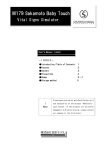
TECHNICAL
Practice
Practice
TELECOM SOLUTIONS
FOR THE
CTG-1
Clock Controlled
Tone Generator
2 1 S T C E N T U RY
April 24, 2012
Add Time Controlled Alert Tones and
Emergency Tones to Your Paging System
Viking's model CTG-1 is a clock controlled tone generator designed to provide accurately timed bong
alert tones or buzzer alert tone sounds over an existing paging system.
The CTG-1 can be programmed to output single,
double or triple alert tones with up to 128 events in a
24 hour period. These bong/buzzer sounds are ideal
for indicating the start and end of shifts, break times,
lunch periods, etc. for factories, schools, or any business requiring an audible indication of specified times. Each day of the week can be
programmed to either on or off, allowing you to turn off the alert tones during specific
days of the week (weekends, etc.)
The CTG-1 has three contact closure inputs for triggering an emergency siren, evacuation signal or a doorbell sound.
Features
Applications
• Accurate 24 hour digital time clock displays
hours and minutes
• Signal the beginning and end of class periods,
breaks, and lunch periods for schools
• User programmable 24 hour, 128 event timer
• Signal the beginning and end of shifts, breaks,
and lunch periods for factories and other
businesses
• Programmable day of week on/off feature
• Programmable single, double or triple alert
tone output (selectable bong or buzzer)
• Three contact closure controlled sounds:
1) Emergency siren (yelp) sound
2) Temporal (slow whoop) evacuation signal
• Provides a doorbell and/or alarm sounds over
an existing paging system, for such applications
as door entry, fire, severe weather, etc.
• Use with Viking's DVA-2WA to provide timed
messages (DOD# 110)
*NFPA/ANSI compliant when used with supporting equipment
3) Doorbell (chime) sound
• Volume controllable, 600 ohm line level audio
output
• Non-volatile programming memory
• Battery backup for maintaining clock time with
factory installed 9V NiMh rechargeable battery
• Two sets of DPDT relay contacts for muting
paging or background music during alert tones
• Switchable 50/60 Hz operation
Phone...715.386.8861
Specifications
Power: 120V AC/13.8V AC 1.25A UL listed adapter provided
Dimensions: 133mm x 91mm x 44mm (5.25” x 3.6” x 1.75”)
Weight: 0.9 Kg (2 lbs)
Environmental: 0°C to 32°C (32°F to 90°F) with 5% to 95%
non-condensing humidity
Connections: 12 position cage clamp terminal strip
Battery Backup: 9V NiMh rechargeable battery (factory
installed) maintains clock time for over 8 hours
Time Base: 50/60Hz AC power line
Time Base Battery Backup Accuracy: +/- 50 ppm
Audio Output: 600 ohm with volume adjust potentiometer, maximum level = 17 dBm/5.4Vrms across 600 ohm load
Relay Output: DPDT rated 125V AC, 30 W (resistive load)
IF YOU HAVE A PROBLEM WITH A VIKING PRODUCT, PLEASE CONTACT: VIKING TECHNICAL SUPPORT AT (715) 386-8666
Our Technical Support Department is available for assistance Monday 8am - 4pm and Tuesday through Friday 8am - 5pm central time. So that we can give you better service, before you call please:
1. Know the model number, the serial number and what software version you have (see serial label).
2. Have your Technical Practice in front of you.
3. It is best if you are on site.
RETURNING PRODUCT FOR REPAIR
RETURNING PRODUCT FOR EXCHANGE
The following procedure is for equipment that needs repair:
1. Customer must contact Viking's Technical Support Department at 715-386-8666 to obtain a Return Authorization (RA)
number. The customer MUST have a complete description of the problem, with all pertinent information regarding the
defect, such as options set, conditions, symptoms, methods to duplicate problem, frequency of failure, etc.
2. Packing: Return equipment in original box or in proper packing so that damage will not occur while in transit. Static
sensitive equipment such as a circuit board should be in an anti-static bag, sandwiched between foam and individually boxed. All equipment should be wrapped to avoid packing material lodging in or sticking to the equipment. Include
ALL parts of the equipment. C.O.D. or freight collect shipments cannot be accepted. Ship cartons prepaid to:
Viking Electronics, 1531 Industrial Street, Hudson, WI 54016
3. Return shipping address: Be sure to include your return shipping address inside the box. We cannot ship to a PO Box.
4. RA number on carton: In large printing, write the R.A. number on the outside of each carton being returned.
The following procedure is for equipment that has failed out-of-box (within 10 days of purchase):
1. Customer must contact Viking’s Technical Support at 715-386-8666 to determine possible causes for the problem. The
customer MUST be able to step through recommended tests for diagnosis.
2. If the Technical Support Product Specialist determines that the equipment is defective based on the customer's input
and troubleshooting, a Return Authorization (R.A.) number will be issued. This number is valid for fourteen (14)
calendar days from the date of issue.
3. After obtaining the R.A. number, return the approved equipment to your distributor, referencing the R.A. number. Your
distributor will then replace the product over the counter at no charge. The distributor will then return the product to
Viking using the same R.A. number.
4. The distributor will NOT exchange this product without first obtaining the R.A. number from you. If you haven't
followed the steps listed in 1, 2 and 3, be aware that you will have to pay a restocking charge.
LIMITED WARRANTY
Viking warrants its products to be free from defects in the workmanship or materials, under normal use and service, for a period of one year from the date of purchase from any authorized Viking distributor or 18 months from the date manufactured, which ever is greater. If at any time during the warranty period, the product is deemed defective or malfunctions, return the product to Viking Electronics, Inc., 1531 Industrial Street, Hudson, WI., 54016. Customer must contact Viking's
Technical Support Department at 715-386-8666 to obtain a Return Authorization (R.A.) number.
This warranty does not cover any damage to the product due to lightning, over voltage, under voltage, accident, misuse, abuse, negligence or any damage caused by use of the product by the purchaser or others. This warranty does not cover
non-EWP products that have been exposed to wet or corrosive environments.
NO OTHER WARRANTIES. VIKING MAKES NO WARRANTIES RELATING TO ITS PRODUCTS OTHER THAN AS DESCRIBED ABOVE AND DISCLAIMS ANY EXPRESS OR IMPLIED WARRANTIES OR MERCHANTABILITY OR FITNESS FOR ANY PARTICULAR PURPOSE.
EXCLUSION OF CONSEQUENTIAL DAMAGES. VIKING SHALL NOT, UNDER ANY CIRCUMSTANCES, BE LIABLE TO PURCHASER, OR ANY OTHER PARTY, FOR CONSEQUENTIAL, INCIDENTAL, SPECIAL OR EXEMPLARY DAMAGES ARISING OUT OF OR RELATED TO THE SALE OR USE OF THE PRODUCT SOLD HEREUNDER.
EXCLUSIVE REMEDY AND LIMITATION OF LIABILITY. WHETHER IN AN ACTION BASED ON CONTRACT, TORT (INCLUDING NEGLIGENCE OR STRICT LIABILITY) OR ANY OTHER LEGAL THEORY, ANY LIABILITY OF VIKING SHALL
BE LIMITED TO REPAIR OR REPLACEMENT OF THE PRODUCT, OR AT VIKING'S OPTION, REFUND OF THE PURCHASE PRICE AS THE EXCLUSIVE REMEDY AND ANY LIABILITY OF VIKING SHALL BE SO LIMITED.
IT IS EXPRESSLY UNDERSTOOD AND AGREED THAT EACH AND EVERY PROVISION OF THIS AGREEMENT WHICH PROVIDES FOR DISCLAIMER OF WARRANTIES, EXCLUSION OF CONSEQUENTIAL DAMAGES, AND EXCLUSIVE REMEDY AND LIMITATION OF LIABILITY, ARE SEVERABLE FROM ANY OTHER PROVISION AND EACH PROVISION IS A SEPARABLE AND INDEPENDENT ELEMENT OF RISK ALLOCATION AND IS INTENDED TO BE ENFORCED
AS SUCH.
FCC REQUIREMENTS
This equipment complies with Part 68 of the FCC rules and the requirements adopted by the ACTA. Inside the front panel
of this equipment is a label that contains, among other information, a product identifier in the format US:AAAEQ##TXXXX.
If requested, this number must be provided to the telephone company.
The REN is used to determine the number of devices that may be connected to a telephone line. Excessive REN's on a
telephone line may result in the devices not ringing in response to an incoming call. In most but not all areas, the sum of
the REN's should not exceed five (5.0) To be certain of the number of devices that may be connected to a line, as determined by the total REN's, contact the local telephone company. For products approved after July 23, 2001, the REN for
this product is part of the product identifier that has the format US:AAAEQ##TXXXX. The digits represented by ## are the
REN without a decimal point (e.g., 03 is a REN of 0.3). For earlier products, the REN is separately shown on the label.
The plug used to connect this equipment to the premises wiring and telephone network must comply with the applicable
FCC Part 68 rules and requirements adopted by the ACTA. If your home has specially wired alarm equipment connected
to the telephone line, ensure the installation of this CTG-1 does not disable your alarm equipment. If you have questions
about what will disable alarm equipment, consult your telephone company or a qualified installer.
If the CTG-1 causes harm to the telephone network, the telephone company will notify you in advance that temporary discontinuance of service may be required. But if advance notice isn't practical, the telephone company will notify the customer as soon as possible. Also, you will be advised of your right to file a complaint with the FCC if you believe it is necessary.
The telephone company may make changes in its facilities, equipment, operations, or procedures that could affect the
operation of the equipment. If this happens, the telephone company will provide advance notice in order for you to make
2
the necessary modifications to maintain uninterrupted service.
If trouble is experienced with the CTG-1, for repair or warranty information, please contact:
Viking Electronics, Inc., 1531 Industrial Street, Hudson, WI 54016 (715) 386-8666
If the equipment is causing harm to the telephone network, the telephone company may request that you disconnect the
equipment until the problem is resolved.
Connection to Party Line Service is subject to State Tariffs. Contact the state public utility commission, public service commission or corporation commission for information.
WHEN PROGRAMMING EMERGENCY NUMBERS AND (OR) MAKING TEST CALLS TO EMERGENCY NUMBERS:
Remain on the line and briefly explain to the dispatcher the reason for the call. Perform such activities in the off-peak
hours, such as early morning or late evenings.
It is recommended that the customer install an AC surge arrester in the AC outlet to which this device is connected. This
is to avoid damaging the equipment caused by local lightning strikes and other electrical surges.
PART 15 LIMITATIONS
This equipment has been tested and found to comply with the limits for a Class A digital device, pursuant to Part 15 of the
FCC Rules. These limits are designed to provide reasonable protection against harmful interference when the equipment
is operated in a commercial environment. This equipment generates, uses, and can radiate radio frequency energy and,
if not installed and used in accordance with the instruction manual, may cause harmful interference to radio communications. Operation of this equipment in a residential area is likely to cause harmful interference in which case the user will
be required to correct the interference at his own expense.
Features Overview
Mode Button: Press to place the CTG-1 in the Lock,
Set Time, Set Day, Set Events or Review/Cancel modes.
Clock and Event Time Setting Buttons: Press the + or
-/CANCEL buttons to increase or decrease time. The /CANCEL switch is also used to cancel an alert tone
event when reviewing programming.
Display: Shows
clock, event time
and mode settings.
VIKING
MODEL CTG-1
-
DIP Switches and Shunts:
See Programming section J.
CLOCK CONTROLLED
TONE GENERATOR
©
ON
PM
TIME
+
/ CANCEL
1
MODE
2
ON
60 Hz
(installed)
OFF
50 Hz
(removed)
LOCK
SET TIME
ALERT TONES
SINGLE
DOUBLE
TRIPLE
SET DAY
SET EVENTS
REVIEW/CANCEL
VOL 1 2 3 4 5 6 7 8 9 10 11 12
9V BATTERY
BACKUP
Alert Tones Programming Buttons:
After setting an event time, press SINGLE, DOUBLE or TRIPLE to program
1, 2 or 3 alert bongs/buzzer sounds for
that event time.
Secondary Button Functions While
in the SET DAY Mode: The SINGLE
button is used to select between day (17) or on/off. The DOUBLE button is
used as a one time setup to program
today’s day of the week.
9V Battery Backup Connection: A standard
rechargeable (NiMh) 9V battery is installed to
maintain the clock time during power outages.
CTG-1 Output Volume Control: Turn clockwise
to increase volume of alert bongs/buzzer sounds,
emergency and door bell (chime) sounds (see
Installation section).
12: Common
11: Emergency Siren (Yelp): Continuous while
shorted to pin 12 (common).
10: Evacuation Sound (Temporal Slow Whoop):
Continuous while shorted to pin 12 (common).
9: Doorbell Chime Sound (Ding Dong):
One chime per closure.
8: N.O.
7: COM
6: N.C.
Relay Contact
5: N.O.
4: COM
3: N.C.
Relay Contact
1 & 2: 600 Ohm Audio Out Pair: Line level output,
connect to input of paging amplifier.
* Note: When the buzzer alert tone is programmed, a double or
triple programmed event will be sounded twice, approximately
three seconds apart.
3
Installation
Connect the CTG-1 between your phone system and your paging amplifier as shown in the diagram below. The factory
installed rechargeable 9V battery will maintain the clock time for over 8 hours.
IMPORTANT: The CTG-1 leaves the factory with the battery backup DIP switch turned OFF to avoid discharging
the battery during shipment. The battery backup DIP switch MUST be set to ON (see Programming section J) to
maintain clock time during a power outage.
VIKING
PA-2A Paging/Loud Ringing
Amplifier System
VIKING ©
POWER 13.8V AC
PAGING
VOLUME
MIN
-
MODEL PA-2A
MIN
MAX
TRUNK OR
PAGING PORT
PAGING
HORN
4
5 6
7 8
9 10
4-6
12345
1
2
3
4
5
6
7
8
DOUBLE
TRIPLE
SET DAY
SET EVENTS
REVIEW/CANCEL
RINGING LINES
1-3
MODE
ALERT TONES
SINGLE
600 OHM
AUDIO OUT
NIGHT
TRANSFER
DRY CONTACT
CLOSURE IN
3
+
LOCK
PAGING - LOUD RINGING
AMPLIFIER SYSTEM
2
TIME
/ CANCEL
SET TIME
MAX
1
PM
RINGING
VOLUME
VIKING
ELECTRONICS
HUDSON, WI 54016
AUDIO LOADING
TALK BATTERY
ALERT TONE
WARBLE / CHIME
CLOCK CONTROLLED
TONE GENERATOR
©
MODEL CTG-1
9
10
VOL 1 2 3 4 5 6 7 8 9 10 11 12
9V BATTERY
BACKUP
Dry Contact Closures from Alarm
Equipment, Doorbell Switch, Etc.
Common
Siren
-or-
Evacuation Signal
Input of
Paging Amp
Paging port
output of
PABX/KSU
Doorbell
Programming
A. Setting the Clock Time
Step 1.
Press the MODE button repeatedly until the SET TIME indicator lights.
Step 2.
Increase or decrease the clock time by pressing the + or -/CANCEL button until the desired time is displayed.
Step 3.
Leave the set time mode by pressing the MODE button.
Note: Either the + or -/CANCEL button MUST be pressed at least once prior to leaving the set time mode. The clock
will then start to run the moment you leave the set time mode, allowing you to synchronize the CTG-1 with your building clocks.
B. Setting the Day of the Week
Note: This step is only required if you want to turn off the Alert Tones on certain days of the week.
4
Step 1.
Press the MODE button repeatedly until the SET DAY indicator lights.
Step 2.
A flashing “A” indicates all 7 days of the week are “on” and today’s day has not been set. The day of the week has
already been set if a flashing number (1-7) and “on” or “of” are displayed.
Step 3.
Select today’s day of the week using the TIME (+ and -/CANCEL) buttons. As a general rule, Sunday is day 1 and
Saturday is day 7. When today’s day of the week is flashing on the display, set it by pressing the DOUBLE alert tone
button. Today’s day number and “on” will now be displayed.
Note: The day of the week setting and turning the alert tones off on specific days of the week is a one time set up and does not
need to be reset unless you have experienced a brown out long enough to discharge the 9V battery backup (approximately 8 hours).
To reset the day of the week and turn off tones on specific days of the week, you must power down the CTG-1, set DIP switch 1 to
OFF, power up the CTG-1 and repeat steps 1-3 above. If you had alert tones turned off on specific days of the week, repeat steps
1-4 in section C. When finished, set DIP switch 1 back to ON.
C. Turning the Alert Tones On/Off for Specific Days of the Week
Step 1.
Press the MODE button repeatedly until the SET DAY indicator lights. The current day of the week and “on” or “of” will
be displayed. “on” = alert tones are ON and “of” = alert tones are OFF for that day of the week.
Step 2.
Pressing the SINGLE button will toggle between flashing the day of the week and flashing “on” or “of”. The flashing portion of the display is the section that can be changed.
Step 3.
With the day of the week flashing, use the TIME (+ and -/CANCEL) buttons to select the day of the week you would like
to set to ON or OFF. When the correct day of the week is displayed, press the SINGLE button to flash “on” or “of”. The
day can then be set to ON or OFF by using the TIME (+ and -/CANCEL) buttons.
Step 4.
Review your day of the week programming by pressing the SINGLE button until the weekday (1-7) is flashing, then increment through each day of the week with the TIME (+) button and monitor each day for its on or off setting. Exit the SET
DAY mode by simply pressing the MODE button.
D. Setting Timed Alert Tones
Step 1.
Press the MODE button repeatedly until the SET EVENTS indicator lights.
Step 2.
Increase or decrease the event time by pressing the TIME (+ or -/CANCEL) button until the desired time is shown.
Step 3.
Move DIP switch 2 to OFF for bong alert tones or ON for buzzer alert tones (see Programming section J).
Step 4.
Press one of the single, double, or triple ALERT TONES buttons to program the number of alert tones you wish to output at the specific event time. A single, double, or triple confirmation beep should be heard.
Step 5.
Repeat steps 2-4 for the remainder of your scheduled events.
Note: If more than 128 events have been entered, a long beep will be heard indicating that the event memory is full.
E. Reviewing and/or Cancelling Timed Alert Tones
Step 1.
Press the MODE button repeatedly until the REVIEW/CANCEL indicator lights.
Step 2.
Press one of the ALERT TONES buttons (single, double, or triple) repeatedly to rotate through the event times associated with that alert tone button. A red LED at the bottom right corner of the time display will light to indicate a buzzer
event time (versus a bong event). Note: Event times are stored in the order of programming, not chronologically.
Step 3.
Press the -/CANCEL button to permanently cancel an event tone. A single acknowledgement tone will be heard. The
next consecutive event for that specific alert tone will then be displayed.
Step 4.
Repeat steps 2-3 as needed to remove the events to be cancelled.
Step 5.
When all events for a given alert tone have been cancelled, the display shows three dashes (- - -).
F. Adjusting Output Volume
Step 1.
Short pins 9 and 12 together momentarily. The doorbell sound will then chime once.
Step 2.
Adjust the volume control potentiometer (see Installation).
Step 3.
Repeat steps 1-2 until the desired volume is achieved.
G. Activating Contact Closure Alarm Tones
Sound
Short Pins...
To activate different sounds, short the corresponding pins with a
dry contact closure as shown right (see Installation, section A).
Doorbell (Ding Dong)
...9 to 12
Evacuation Sound (Slow Whoop)
...10 to 12
Note: The evacuation sound and siren will be repeated continuously, as long as the closures are maintained.
Siren (Yelp)
...11 to 12
5
H. Locking the CTG-1 for Operation
When finished programming, press the MODE button until the LOCK indicator lights. In the lock mode, the time and
alert tone keys will be disabled and the current time will be displayed with the colon flashing once per second.
I. Clearing the Alert Tone Memory
Turn DIP switch 1 OFF. Unplug the CTG-1 from power. Pause a few seconds and then plug the CTG-1 back in. Push
the CANCEL and SINGLE buttons at the same time and release them. Repeat, and after releasing the buttons the second time a long beep will be heard indicating that the CTG-1’s memory has been cleared. Turn DIP switch 1 back ON
to enable battery backup.
Note: After completing this procedure, it will be necessary to reset the clock time (see Programming section A), and
if enabled, the day of the week (see Programming section B) and alert tones on/off (see Programming section C).
J. DIP Switch and Shunt Settings
ON
Switch
Position Description
1
OFF
Battery backup disabled
1
ON
Battery backup enabled
2
OFF
Bong alert tones (factory setting)
2
ON
Buzzer alert tones
Shunt Position
1
2
ON
60 Hz
(installed)
OFF
50 Hz
(removed)
Description
Installed
60 Hz power line frequency (factory setting)
Removed
50 Hz power line frequency
Internal View of the CTG-1
K. Changing the Power Line Frequency Setting
Unplug the CTG-1 from power and turn DIP switch 1 OFF. Remove the shunt as shown in the diagram above to change
from 60 Hz to 50 Hz, or replace it to change from 50 Hz operation to 60 Hz. Power the CTG-1 back up and turn DIP
switch 1 ON. Set the CTG-1 to the current time.
Operation
When the clock time matches an event time and that day is set to “ON” or “A”, the CTG-1 will output the corresponding single, double or triple bong or buzzer alert tone. The CTG-1 will also open terminals 3 and 4 (normally closed) and close terminals 4 and 5 (normally open), allowing the capability of switching out the audio from the phone system and switching in
the alert tone from the CTG-1. Similarly, while a contact closure is made shorting pins 9, 10 or 11 to pin 12, the CTG-1 will
output the corresponding sound (doorbell, evacuation signal or emergency siren). In the case of the siren or evacuation
signal, terminals 3 and 4 will open, and terminals 4 and 5 will close and the sound will continue for the duration of the contact closure input. Terminals 3, 4 and 5 will return to their normal states at the end of each doorbell tone.
Note: Terminals 6, 7 and 8 will operate the same as terminals 3, 4 and 5 but are electronically isolated from terminals 3, 4
and 5 for switching a separate device.
IMPORTANT: While operating, the CTG-1 continuously checks the event time information stored in memory. If a problem
is detected, the CTG-1 displays “EEE” to indicate an error. Normal clock function continues in the background. To clear
the error, press any button and the CTG-1 will return to normal operation. If the “EEE” display persists, contact Viking
Technical Support at 715-386-8666.
6
Sound Output Specifications
A. Bong Alert Tone
1 sec
3 sec
3 sec
1 sec
3 sec
1 sec
On
500
Hz
500 Hz
Off
Single
500
Hz
500 Hz
500
Hz
500 Hz
Triple
Double
B. Buzzer Alert Tone
On
Off
3 sec
.8 sec
60 Hz
60 Hz
Single
.8 sec
.8 sec
3 second break
then repeated
a second time
60 Hz
.6
sec
.6
sec
.6
sec
60
Hz
60
Hz
60
Hz
3 second break
then repeated
a second time
Triple
Double
C. Doorbell (Ding Dong)
On
Off
3 sec
.3 sec
One per closure across pin 9 and pin 12.
840 Hz
500 Hz
D. Evacuation Signal (Temporal Slow Whoop)
.5 sec
.5 sec
.5 sec
.5 sec
.5 sec
On
1.5 second
Break
Continuously repeated while pin 10 is shorted to pin 12.
Off
200 Hz
700 Hz
E. Siren (Yelp)
300 ms
300 ms
300 ms
On
Continuously repeated while pin 11 is shorted to pin 12.
Off
280 Hz
2270 Hz
280 Hz
2270 Hz
7
Other Applications
Use Viking's DVA-2WA Digital Voice Announcer (DOD# 110) in conjunction with a CTG-1 to provide time activated promotional voice
messages over an existing paging system. The CTG-1 will be used only to provide time activated contact closures to the DVA-2WA for
initiating multiple (up to 7.5 minutes total length) promotional messages. Note: It is recommended that a UPS (uninterruptible power
source) be used to maintain the proper message order in the DVA-2WA during a power outage.
Model CTG-1
Model DVA-2WA
Up to (3) 8 Ohm Speakers
or (16) 45 Ohm Speakers
Background
Music Source
The store will be closing
in 10 minutes. Please bring
all items to the check out...
- or To Input of Paging
Amplifier, Model M15W
shown (not included)
Product Support Line...715.386.8666
Fax Back Line...715.386.4345
Due to the dynamic nature of the product design, the information contained in this document is subject to change without notice. Viking Electronics, and its affiliates and/or subsidiaries assume no responsibility for errors and omissions contained in this information. Revisions of this document or new editions of it may be issued to incorporate such changes.
DOD# 460
8
Printed in the U.S.A.
ZF300500 Rev J