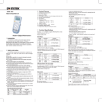
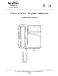
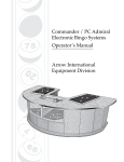
1
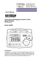
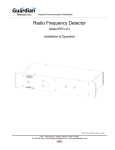
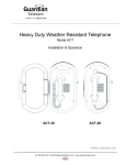
Alarm Tone Generator Model AG17 Installation & Operation P005089 Rev. C 150930 9/30/2015 12:25 PM Ph: 403.258.3100 \ email:[email protected] \ www.guardiantelecom.com Guardian Telecom Inc. Installation and Operation Model AG17 Table of Contents Package Contents ..................................................................................... 2 Overview.................................................................................................... 3 AG17 Tone Generator Models .................................................................. 3 Features .................................................................................................... 3 Front Panel ........................................................................................... 4 Rear Panel ............................................................................................ 5 Installing the AG17 .................................................................................... 7 Unit Operation ........................................................................................... 8 Default Settings .................................................................................... 8 Alarm Logic Inputs ................................................................................ 8 Alarm Logic Outputs ............................................................................. 9 Override Audio / Logic Inputs.............................................................. 10 Audio / Logic Outputs ......................................................................... 10 Input Volume Control .......................................................................... 10 Output Volume Control ....................................................................... 10 Clear / Reset Terminals ...................................................................... 10 Clear / Reset Switches (Front Panel) Local ........................................ 10 Clear / Reset Terminals (Rear Panel) Remote ................................... 10 Relay Contacts (Optional)................................................................... 10 Programming the AG17........................................................................... 11 Setting Input Channel Alarm Tones .................................................... 11 Setting Triggering and Attenuation ..................................................... 12 Setting the Timer for Pulse-Triggered Logic Inputs ............................ 13 Setting the All Clear Tone ................................................................... 13 Interpreting the LED Display Pattern Table ............................................. 13 Displaying All Parameters Stored In Non-Volatile RAM...................... 14 Product Specifications ............................................................................. 15 Warranty .................................................................................................. 17 Disclaimer................................................................................................ 17 Warning ................................................................................................... 17 Service Telephone Number..................................................................... 17 1-800-363-8010 .................................................................................. 17 Feedback................................................................................................. 17 Guardian Product Return......................................................................... 18 Table of Figures Figure 1 - Front Panel ...........................................................................................................4 Figure 2 - Rear Panel............................................................................................................5 Figure 3 - Typical Installation ................................................................................................6 Package Contents One AG17 Tone Generator One Installation and Operation Manual Page 2 Guardian Telecom Inc. Installation and Operation Model AG17 Overview Alarm Tone Generator The Guardian Telecom AG17 is a state-of-the-art signal generator with a ten-tone signal library designed to work with general alarm and public address systems. Alarm tone, priority, duration and triggering are programmable to meet specific operating and workplace conditions. Installation is simple. An audio override facility also allows voice-paging announcements. The AG17 Tone Generator is one component in Guardian Telecom's full line of paging system products, which include amplifiers and signal and switch conditioning equipment. AG17 Tone Generator Models Model P5970 AG17 Model P5960 AG17 with optional relay board. Features Programmable 10 tone alarm library user programmable microprocessor to customize tone priority, duration, triggering, muting and attenuation eight channels for output signal priority logic outputs that mirrors control input momentary or latching inputs LED alarm activation indicators output level control Compact fits on a standard 19" equipment rack, requiring only 2 rack units (2U) Audio Override for page/talk announcements Page 3 Guardian Telecom Inc. Installation and Operation Model AG17 Front Panel LED Indicators, Clear and Reset Switches 1. Power LED Illuminates when the unit is on. 2. Alarm LEDs Illuminates when the alarm is active. 3. Clear Switch Activates the 3-Beep Clear tone. 4. Reset Switch Turns off the highest priority tone active. Figure 1 - Front Panel Page 4 Guardian Telecom Inc. Installation and Operation Model AG17 Rear Panel The rear panel of the AG17 is where all the connections are made. 1. Clear/Reset Terminals Connect Clear and Reset switches. 2. Alarm Logic Outputs Trigger external devices. 3. Audio / Logic Output Connect external devices. 4. Output Volume Control Adjusts overall audio output level of the AG17. 5. Input Volume Control Adjusts input level of the Override Audio Signal. 6. Override Audio / Logic Input Overrides tones when the logic signal is present. 7. Programming Jack Connects a DTMF tone generating analog telephone for programming the AG17. 8. Alarm Logic Inputs Activate any of 8 available alarm tones. 9. Relay Contacts (Optional) Trigger external devices. 10. Fuse Fuse replacement with 1/2A, 3AG, 250V fast blow fuse only. 11. Power On/Off Switches unit on or off. POWER 1 A B C ALARM RELAY CONTACTS 3 4 5 6 2 A B C A B C A B C A B C 7 A B C RELAY CONTACTS 8 A B C A B C A B C NORMALLY OPEN COMMON NORMALLY CLOSED CLEAR RESET + - + - 1 2 3 4 5 6 7 8 CC OUTPUT A L + - + - VOLUME O/P I/P INPUT A L + - + - ALARM LOGIC IN INPUT / OUTPUT A L AUDIO LOGIC F U SE F U SE ALARM LOGIC OUT 1 2 3 4 5 6 7 8 CC FUSE 1/2A GUARDIAN TELECOM INC. CALGARY, ALBERTA, CANADA Figure 2 - Rear Panel Page 5 120VAC Guardian Telecom Inc. Installation and Operation Model AG17 AG-17 Alarm Tone Generator POWER 2 1 A B C ALARM RELAY CONTACTS 3 4 5 6 A B C A B C A B C A B C A B C 7 RELAY CONTACTS 8 A B C A B C A B C NORMALLY OPEN COMMON NORMALLY CLOSED CLEAR RESET + - + - 1 2 3 4 5 6 7 8 CC VOLUME O/P I/P INPUT A L + - + - ALARM LOGIC IN INPUT / OUTPUT A L + - + - AUDIO LOGIC F U SE F U SE OUTPUT A L ALARM LOGIC OUT 1 2 3 4 5 6 7 8 CC FUSE 1/2A GUARDIAN TELECOM INC. CALGARY, ALBERTA, CANADA Logic Pair Audio Pair 120VAC Alarm Activation Manual Push Button Push to Talk Button (Logic) Input 70/100V Paging Line Output Power Amplifier Paging Speakers Relay Power Supply + Strobe Lights 120V AC Neu. Figure 3 - Typical Installation Page 6 Fire & Gas Alarm System Guardian Telecom Inc. Installation and Operation Model AG17 Installing the AG17 Carefully plan input and output connections. Identify input and output devices. Prioritize alarm inputs. Plan output connections to correspond with input priorities. Tip: Familiarize yourself with unit capabilities and functions. See: Typical Installation drawing and Unit Operation details. Tip: Input #1 is the highest priority. Follow all appropriate electrical codes for the installation. Inspect the product for shipping damage. Tip: If the product is damaged, notify the carrier immediately. Do not open or attempt to open the AG17 unit. There are no user serviceable parts inside the unit. Tip: Unauthorized modifications void the product warranty. Choose a location on a standard 19" equipment rack with 2 rack units (2U) of available space. Have a standard touch-tone telephone available to program the AG17 after installation is complete. Secure the unit to the rack. Ensure all devices that will be connected to the AG17 are turned off. Plug the AG17 into the power source but do not apply power to the AG17 before connecting input and output devices. Use the following sequence when wiring connections: Alarm Logic Input Alarm Logic Output Clear/Reset (optional) Input Audio/Logic Output Audio/Logic Alarm Relay Contacts (optional) See: Programming, below. See: Unit Operation for more details. See: Unit Operation for wiring caution on Logic Output. Page 7 Guardian Telecom Inc. Installation and Operation Model AG17 Refer to your individual input/output/priority plan and wire all required connections as follows: Remove quick disconnect connector (Phoenix Combi-Con). Wire the connector. Plug the connector back into the unit. When connections are complete, apply power to the AG17. The AG17 operates with default settings as soon as power is applied. If customized settings are required, program the AG17 using a touch-tone telephone. Apply power to all input devices. See: Unit Operation and Programming the AG17, below. Unit Operation Default Settings Pulse-Trigger Logic Input 60 dB Attenuated Tones All Clear Tone Enabled Timer Reset Disabled Channel 1 - Beep, High Channel 2 - High / Low Channel 3 - Warble Channel 4 - Yelp, Fast Channel 5 - Whoop, Slow Channel 6 - Siren Channel 7 - Steady Channel 8 - Beep, Low Alarm Logic Inputs Logic Input Channels are used to connect devices (e.g., fire and gas detection systems) that activate alarm tones. The eight channels are arranged in priority as follows: Channel #1 is the highest priority. Channel #8 is the lowest priority. Each channel has an assigned default tone. Page 8 See: Default Settings, above. Guardian Telecom Inc. Installation and Operation Model AG17 To assign a tone other than the default to any channel, program the unit. The input channel tone broadcasts when the channel is activated by a contact closure. If a higher priority input channel is already activated, the lower priority tone does not broadcast. To select either a level-triggering or positive edge pulse-triggering signal, program the unit. The AG17 is preset for a Pulse-Trigger Logic Input default. Tip: There are 10 tones to choose from. See: Programming, Setting Input Channel Alarm Tones, below. Tip: The type of triggering selected is applied to all input channels. See: Programming, Setting Triggering and Attenuation, below. Lower priority triggered channels are suppressed until higher priority channels are released. Front panel LEDs indicate all activated channels. The alarm tone associated with the activated, highest priority channel is generated until the Timer or the Reset Switch resets it. The unit is preset with the Timer Reset disabled so tones continue to sound until the reset switch is pressed. To enable the Timer, program the unit. Timer duration on the AG17 can be programmed for tones operating from 30 seconds to 30 minutes. Tip: The Timer determines the length of time the alarm sounds before it automatically resets. Pressing the Reset switch clears the highest priority activated channel. See: Programming, Setting the Timer for Pulse Triggered Logic Inputs, below... Alarm Logic Outputs Logic Outputs are used to connect devices (e.g., strobe lights, relays) that trigger when an alarm is activated. Each Logic Output Channel is associated with the corresponding Logic Input Channel number. Wire Logic Outputs according to standard Open-drain / Open-collector procedures. Do not apply positive DC voltage to the source terminal or hook-up AC voltage across the logic terminals. Page 9 Tip: Each Logic Output Channel is an isolated open-drain circuit. Note: The maximum rating for each logic output is 300 mA at 40 V DC. Caution: Applying positive DC voltage to the source terminal or AC voltage across the source/drain terminals will damage the AG17. Guardian Telecom Inc. Installation and Operation Model AG17 Override Audio / Logic Inputs Override Audio / Logic Inputs have a higher priority than alarm tone signals. A contact closure on the Override Audio / Logic Input suppresses any existing alarm tone and broadcasts the signal on the Override Audio Input. The AG17 is preset for 60 dB attenuated alarm tones. To select attenuation, See: Programming, Setting Triggering and program the unit. The AG17 can be programmed so that the alarm tone is Attenuation, below. completely muted by the Override or attenuated by 10dB, 20dB, or 60dB. Audio / Logic Outputs The Audio output connects to devices such as paging amplifiers or other signal conditioning equipment. The Logic output can enable activation of amplifiers that employ a “sleep” condition to eliminate noise in a “no signal” present application. Input Volume Control Input Volume controls the Override Audio level. Override Audio level can be adjusted to the same level as the tones generated by the AG17. Output Volume Control Output Volume controls the Audio output of the AG17. The Audio Output level can be adjusted according to the input requirements of the external device (e.g., amplifier) being connected. Clear / Reset Terminals Pulse triggered alarms are reset by the reset feature. Level triggered alarms are reset by the removal of the level activation logic signal. Clear / Reset Switches (Front Panel) Local The Clear switch on the front panel activates a three-tone Clear Signal. The Reset switch on the front panel turns off the highest priority active alarm tone. Clear / Reset Terminals (Rear Panel) Remote Clear / Reset terminals are used to connect remote clear and reset devices. Clear activates a three-tone Clear Signal. Reset turns off the highest priority active alarm tone. Relay Contacts (Optional) The optional relay board provides eight relay contacts. Each relay contact is associated with an Input Channel. When an Input Channel is activated by contact closure, the associated relay activates and remains active until the alarm is reset. Page 10 Tip: The Reset switch operates when the AG17 is in the Pulse Trigger mode. Guardian Telecom Inc. Installation and Operation Model AG17 Programming the AG17 Connect a DTMF tone-generating analog telephone to the RJ11 jack on the rear panel. Lift the telephone handset off the hook. Check to ensure the Power LED is illuminated. Check to ensure the front panel LED's are not illuminated. If a value is entered beyond the acceptable range during programming, all front panel LEDs blink once to alert the programmer. At any time during programming, you can check parameters to confirm programming accuracy. Follow the Setting Tables below and use the touch-tone telephone keys to program the AG17. When programming is complete, disconnect the telephone from the AG17. Setting Input Channel Alarm Tones Press the # key, then the Channel Number (1-8), then the Alarm Tone Number (0-9). # Input Channel Number 1 - 8 Alarm Tone 0 - 9 # 1 = Channel 1 1 = Siren # 2 = Channel 2 2 = Warble # 3 = Channel 3 3 = Yelp, Slow # 4 = Channel 4 4 = Yelp, Fast # 5 = Channel 5 5 = Whoop, Slow # 6 = Channel 6 6 = Whoop, Fast # 7 = Channel 7 7 = High/Low # 8 = Channel 8 8 = Steady 9 = Beep, Low 0 = Beep, High Page 11 See: Programming, Displaying All Parameters Stored in Non-Volatile RAM, below. Guardian Telecom Inc. Installation and Operation Model AG17 Setting Triggering and Attenuation Press the # key, then the number 0, then the Triggering and Attenuation Number (1-9). # 0 Triggering and Attenuation 1 - 9 # 0 1= Level triggered inputs 10dB Tone attenuation # 0 2= Level triggered inputs 20dB Tone attenuation # 0 3= # 0 4= Level triggered inputs 60dB Tone attenuation Level triggered inputs Tone totally muted. # 0 5= Pulse triggered inputs 10dB Tone attenuation # 0 6= Pulse triggered inputs 20dB Tone attenuation # 0 7= Pulse triggered inputs 60dB Tone attenuation # 0 8= Pulse triggered inputs Tone totally muted # 0 9= Default Settings Pulse trigger Inputs 60dB attenuated tones Page 12 Guardian Telecom Inc. Installation and Operation Model AG17 Setting the Timer for Pulse-Triggered Logic Inputs Press the * key, then the Timer Duration Number (1-9). Timer Duration 1 - 9 * * * * * * * * * * 1 = 30 seconds 2 = 1 minute 3 = 2 minutes 4 = 5 minutes 5 = 10 minutes 6 = 15 minutes 7 = 20 minutes 8 = 30 minutes 9 = Timer Disabled - all tones continue to sound until reset. Setting the All Clear Tone Press the # key, then the number 9, then the Enable or Disable Number (1-2). # 9 1 = Enable # 9 2 = Disable Interpreting the LED Display Pattern Table After pressing the * and then the 0, four distinct pattern sequences will be observed. The LEDs will flash in 0.5 second intervals. 1. The first sequence will be the flashing of LEDs 1 – 4. Count the number of flashes and refer to Section 1, LED Input Triggering Mode and Attenuation for the selected operation. 2. The second sequence will step through the eight LEDs. Count the number of flashes on each led and refer to section 2 for the alarm tone that is programmed for that channel. 3. The third sequence is for All Clear Tone and LEDs 1 – 4 will flash if it is disabled and 5 – 8 will flash if activated as Section 3 indicates. 4. The final sequence involves only LED #1 for Flash Timer Correlation. Count the number of flashes and refer to Section 4 for the selected timing. Page 13 Guardian Telecom Inc. Installation and Operation Model AG17 Displaying All Parameters Stored In Non-Volatile RAM See: LED Display Pattern Table. Press the * key, then the number 0. LED Display Pattern Table SEQUENCE #1 1 2 3 4 5 6 7 8 Input Triggering Mode and Attenuation On = LED Flashing ON ON ON ON X X X X 1 Flash Level 10dB X = LED Not Flashing ON ON ON ON X X X X 2 Flashes Level 20 dB ON ON ON ON X X X X 3 Flashes Level 60 dB ON ON ON ON X X X X 4 Flashes Level Mute ON ON ON ON X X X X 5 Flashes Pulse 10 dB ON ON ON ON X X X X 6 Flashes Pulse 20 dB ON ON ON ON X X X X 7 Flashes Pulse 60 dB ON ON ON ON X X X X 8 Flashes Pulse Mute SEQUENCE #2 1 2 3 4 5 6 7 8 Flash/Tone Correlation (See Flash=Tone) Flash = Tone ON X X X X X X X Channel 1 - 1-10 Flashes 1 Flash = Siren X ON X X X X X X Channel 2 - 1-10 Flashes X X ON X X X X X Channel 3 - 1-10 Flashes 4 Flashes = Yelp, Fast X X X ON X X X X Channel 4 - 1-10 Flashes 5 Flashes = Whoop Slow X X X X ON X X X Channel 5 - 1-10 Flashes X X X X X ON X X Channel 6 - 1-10 Flashes 8 Flashes = Steady X X X X X X ON X Channel 7 - 1-10 Flashes 9 Flashes = Beep, Low X X X X X X X ON Channel 8 - 1-10 Flashes 10 Flashes = Beep, High SEQUENCE #3 ON ON ON ON X X X X All Clear Tone Enabled X X X X ON ON ON ON All Clear Tone Disabled ON X X X X X X X Flash/Timer Correlation ON X X X X X X X 1 Flash = 30 Seconds ON X X X X X X X 2 Flashes = 1 Minute ON X X X X X X X 3 Flashes = 2 Minutes ON X X X X X X X 4 Flashes = 5 Minutes ON X X X X X X X 5 Flashes = 10 Minutes ON X X X X X X X 6 Flashes = 15 Minutes ON X X X X X X X 7 Flashes = 20 Minutes ON X X X X X X X 8 Flashes = 30 Minutes ON X X X X X X X 9 Flashes = Timer Reset Disable SEQUENCE #4 Page 14 2 Flashes = Warble 3 Flashes = Yelp, Slow 6 Flashes = Whoop, Fast 7 Flashes = High/Low Guardian Telecom Inc. Installation and Operation Model AG17 Product Specifications ELECTRICAL REQUIREMENTS INPUT VOLTAGE 120VAC OR 240VAC AVAILABLE WITH FACTORY ORDER INPUT FREQUENCY 50/60HZ MAXIMUM CURRENT CONSUMPTION 12VA FUSE 1/2A; 3AGC, 250VOLT, FAST-BLOW ALARM LOGIC INPUTS (8) ACTIVATING DEVICE DRY CONTACT RELAY MINIMUM OPEN COLLECTOR/ OPEN DRAIN OUTPUT 5V @ 1mA MIN. OVERRIDE AUDIO INPUT INPUT IMPEDANCE 600 OHMS @ 750VRMS MAX. CONTROL INPUT VOLUME CONTROL POT OVERRIDE LOGIC INPUT ACTIVATING DEVICE DRY CONTACT RELAY MINIMUM OPEN COLLECTOR/ OPEN DRAIN OUTPUT 5V @ 1 mA MIN. ALARM LOGIC OUTPUTS (8) MAXIMUM OPEN DRAIN OUTPUT 300 mA @ 40VDC MAX AUDIO OUTPUT OUTPUT IMPEDANCE 33 OHMS @ 1VRMS MAX CONTROL OUTPUT VOLUME CONTROL POT AUDIO SIGNALS ALARM TONES TONE 1: SIREN 400 HZ - 1000 HZ, 0.3 SECONDS TONE 2: WARBLE 400 HZ - 1000 HZ, 0.3 SECONDS TONE 3: YELP, SLOW 400 HZ - 1000 HZ, 4.2 SECONDS TONE 4: YELP, FAST 400 HZ - 1000 HZ, 1.6 SECONDS TONE 5: WHOOP, SLOW 400 HZ - 1000 HZ, 4.2 SECONDS TONE 6: WHOOP, FAST; 400 HZ - 1000 HZ, 1.6 SECONDS TONE 7: HIGH / LOW 560 HZ - 760 HZ, 1.2 SECONDS TONE 8: STEADY 1000 HZ TONE 9: BEEP, LOW; 120 HZ, 1.2 SECONDS TONE 10: BEEP, HIGH 1000 HZ, 1.2 SECONDS CLEAR: 3 BEEP 1000 HZ ALARM TONES ATTENUATED 10 dB, 20 dB , 60 dB , MUTED Page 15 Guardian Telecom Inc. Installation and Operation Model AG17 OPTIONAL ALARM RELAY 8 OUTPUTS IN FORM C CONTACTS MAXIMUM OUTPUT CONTACT CAPACITY PROGRAMMING JACK VAC: 120 VAC @ 1 A MAX. , VDC: 30 VDC @ 2 A MAX. RJ11C MECHANICAL BODY CONSTRUCTION MILD STEEL POWDER COATED BODY DIMENSIONS 419 X 207 X 77 MM (16.5 X 8.2 X 3.1 IN.) NET WEIGHT 3.2KG (7 LBS.) CONNECTION AUDIO REMOVABLE CONNECTION PLUG CONNECTION LOGIC REMOVABLE CONNECTION PLUG CONNECTION POWER 120VAC U GROUND POWER CORD MOUNTING STANDARD RACK MOUNTING (2 UNITS) Page 16 Guardian Telecom Inc. Installation and Operation Model AG17 Warranty Guardian Telecom warrants your product to be free of defects in material and workmanship for a period of one year. Guardian Telecom will repair or replace any defective unit that is under warranty free of charge. This warranty is null and void if any non-authorized modifications have been made to this product, or if it has been subjected to misuse, neglect, or accident. This warranty covers bench repairs only; such repairs must be made at Guardian Telecom or an authorized service depot. Guardian Telecom is not responsible for costs incurred for on-site service calls, freight, or brokerage. A return authorization must be obtained prior to warranty claims or repairs. Disclaimer The products covered by this manual are designed for use in Industrial Environments and/or Hazardous Locations. Due to the range of possible applications for these instruments the manufacturer will not be responsible for damages or losses of any kind suffered as a result of the use of this product, including consequential damages. Warning This device may be opened and reassembled by qualified personnel only, for the purposes of installing the product, making adjustments and replacing components, following the instructions in the product manual. Before opening this telephone disconnect the wiring at the demarcation block. High voltages may be present in this product when connected to telephone wiring. Service Telephone Number 1-800-363-8010 Guardian Telecom provides a customer service telephone number which is toll-free within North America. If you need assistance when installing or operating this product, please call the toll-free telephone number between regular business hours (8:00AM-5:00PM), Mountain Standard Time. If you are calling outside of regular business hours, please leave a detailed message, and a member of Guardian Telecom’s Service Department will return your call as soon as possible. If your product requires service, Guardian personnel will supply you with an RMA (return materials authorization) number over the telephone or through our web site product return page. This number must be included with your return address and the name of the person to contact. Guardian Telecom Inc. Toll-free 1-800-363-8010 Ph. (403) 258-3100 Fax. (403) 253-4967 www.guardiantelecom.com Feedback Guardian Telecom continually strives to make reliable, durable, and easy to use products. If you, as an installer or user of our equipment, have any suggestions for improvements to this or any of our products or documents, including this manual, we would appreciate hearing from you. Page 17 Guardian Telecom Inc. Installation and Operation Model AG17 Guardian Product Return Guardian products have been quality tested and are in full working order when shipped from the factory, given the rugged nature of these products shipping is not expected to damage a unit. In the unlikely event of a malfunction Guardian follows the three step procedure below. Step I - On-Site Correction The most common source of difficulties with a new product is improper installation in one of two ways: incorrect wiring connections or connection to an incorrect power source. Product wiring needs to be properly connected to the on-site wiring. Correct wiring instructions are shown in the user manual included with the product. Step II - Return Materials Authorization (RMA) When a product has been installed following user manual instructions, and the unit fails to operate, the user must contact Guardian Telecom to obtain authorization to return the product. After providing information on the product, the owner and the nature of the problem, Guardian will issue a RMA number, to be shown on documentation returned with the product. In addition to the RMA number, shipping documents should include name, address and telephone number of the owner along with contact information for the person responsible for the repair and/or the user who identified the malfunction. (Where a product is being returned for repair from outside of Canada, customs documentation must show the product’s serial number, date of export [date of purchase], and a notation that the equipment is: “Canadian goods returning.”) Step III - Factory Authorized Service Once received, each product is carefully inspected and tested. If the product is under warranty, repairs are completed and the product returned to the owner, generally within five working days of receipt by the factory. A product that has been subjected to misuse, neglect or accident or is beyond the warranty period will be evaluated. The service department will provide the owner’s representative with a repair cost estimate. Once approved, repairs are completed and the product returned, generally within five working days. Page 18 Guardian Telecom Inc. Installation and Operation Model AG17 Notes: Model No. Part No. Serial No. Date of Purchase Page 19 Guardian Telecom Inc. Toll-free 1-800-363-8010 Phone (403) 258-3100 Fax. (403) 253-4967 http://www.guardiantelecom.com E-mail: mailto:[email protected] (Click to open message box) CONNECTED. PROTECTED. © Guardian Telecom Inc. 2015