1
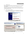
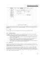
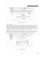
AAM6010EV-T4 CPE User Manual
AAM6010EV-T4
User Manual
Rev. 1.02
Version date: Sep. 15, 2004
AAM6010EV-T4 User Manual
Table of Contents
1.
Introduction
1.1
Features & System Requirements
2. Your CPE at a glance
2.1
Ports and buttons (Back panel)
2.2
LED description (Front panel)
2.3
LED table & parts list
3. Getting Start
3.1
Connecting the Hardware
3.1.1
Connect the ADSL line
3.1.2
Connect the computers or a LAN
3.1.3
Attach the power adapter
3.1.4
Turn on your computer
3.2
Configuring Your PC
3.2.1
Windows® USB Driver Installation
3.2.2
Windows XP:
3.2.3
Windows 2000:
3.2.4
Windows Me:
3.2.5
Windows 95, 98:
3.2.6
Windows NT 4.0:
3.2.7
Assigning IP to your PC automatically by DHCP
4. Setting up your CPE
4.1
Log into your CPE
4.2
Home screen
4.3
Setup
4.3.1
Wide Area Network connection
4.3.2
Local Area Network connection
4.4
Configuring the WAN
4.4.1
New Connection
4.4.2
Modify an Existing Connection
4.4.3
Modem setup
4.5
Configuring the LAN
4.5.1
Enable/Disable DHCP
4.5.2
Changing the CPEs IP address
4.5.3
Firewall/NAT Services
4.6
Advanced
4.6.1
UPnP
4.6.2
Port Forwarding
4.6.3
IP QoS/IP filters
4.6.4
Access Control
4.6.5
LAN clients
4.6.6
Bridge Filters
4.6.7
Multicast/IGMP Snooping
4.6.8
Static Routing
4.6.9
Dynamic Routing
4.7
Tools
2
4
4
5
5
5
5
7
7
7
7
7
7
8
8
10
11
11
12
13
13
14
14
14
15
16
16
16
16
22
22
22
22
24
24
25
25
25
26
27
27
28
29
30
31
32
2
AAM6010EV-T4 User Manual
4.7.1
System Commands
4.7.2
Remote Log
4.7.3
User Management
4.7.4
Update Gateway
4.7.5
Ping Test
4.7.6
Modem Test
4.8
Status
4.8.1
Network Statistics
4.8.2
Connection Status
4.8.3
DHCP Clients
4.8.4
Modem Status
4.8.5
Product Information
4.8.6
System Log
5. Appendix A: Troubleshooting
5.1
The CPE is not functional
5.2
I can’t connect to the CPE.
5.3
The LEDs blink in a sequential pattern.
5.4
The DSL Link LED continues to blink but does not go solid
5.5
The DSL Link LED is always off
6. Router terms
3
32
32
33
33
34
35
35
35
35
35
35
35
35
36
36
36
36
37
37
38
3
AAM6010EV-T4 User Manual
1.
Introduction
Congratulations on becoming the owner of an AAM6010EV-T4 CPE (Customer Premises Equipment).
Your LAN (Local Area Network) will now be able to access the Internet via the CPE’s ADSL connection.
This User Manual will show you how to set up the AAM6010EV-T4 CPE, and how to customize its
configuration to get the most out of this product.
1.1
Features & System Requirements
z
•
•
•
•
•
•
•
•
•
•
•
•
•
•
z
Features
Equipped With a 1 Port 10/100 Ethernet
Connects multiple PCs to the Internet with just one WAN IP Address (when configured in router
mode with NAT enabled)
Configurable through user-friendly web pages
Supports Single-Session IPSec and PPTP Pass-Through for Virtual Private Network (VPN)
Several popular games are already pre configured. Just enable the game and the port settings are
automatically configured.
Configurable as a DHCP Server on Your Network
Compatible with virtually all standard Internet applications
Industry standard and interoperable DSL interface
Address Filtering, DMZ Hosting, and Much More
Simple web based status page displays a snapshot of your system configuration, and links to the
configuration pages
Downloadable flash software upgrades
Support for up to 8 Permanent Virtual Circuits (PVC)
Support for up to 8 PPPOE sessions
Supports Classical IP over ATM (CLIP or also referred to as RFC5177)
System Requirements
In order to use the AAM6010EV-T4 CPE for Internet access, you must have the following:
f ADSL service subscription from your ISP.
f One computer containing an Ethernet 10BaseT/100BaseT network interface card (NIC).
f (Optional) An Ethernet hub/switch, if you are connecting the device to several computers on an
Ethernet network.
f For system monitoring or configuration using the supplied web-based program: a web browser such as
Internet Explorer Version 5.5 or later.
4
4
AAM6010EV-T4 User Manual
2.
Your CPE at a glance
Your CPE has many ports, switches and LEDs. Let’s take a look at the different options. Depending upon
your model of CPE, your CPE may have some or all of the features listed below
2.1
Ports and buttons (Back panel)
z
Power is where you connect the power.
z
Reset Button: The reset button is used to reset the CPE to default setting. You may need to
reset the CPE if you loose network connectivity or you loose the ability to interface to the CPE
via the web interface. To reset the CPE, simply press the reset button for about 5-10 seconds
and release. After about 30 seconds the CPE will become operational.
z
LAN (local area network) port: connect to Ethernet network devices, such as a PC, hub,
switch, or router.
z
USB (universal serial port): connects to a PC’s serial port. The CPE only supports Window’s
based PCs via an RNDIS driver (included in the software).
z
DSL port: This is the WAN interface that connects directly to your phone line.
2.2
LED description (Front panel)
z
Power LED: On indicates that the power is supplied to the CPE
z
Status LED: The Status LED serves two purposes. If the LED is continuously lit, the DSL
interface is successfully connected to a device through the WAN port. If the LED is flickering,
it is an indication that the modem is training.
z
Activity LED: The Activity LED flash during ADSL data transfer.
z
LAN LED: The LAN’s LED serves two purposes. If the LED is continuously lit, the Ethernet
interface is successfully connected to a device through the LAN port. If the LED is flickering, it
is an indication of any network activity.
z
USB LED: The USB’s LED serves two purposes. If the LED is continuously lit, the USB
interface is successfully connected to a device through the LAN port. If the LED is flickering, it
is an indication of any network activity.
2.3
LED table & parts list
z
LED Table
The LEDs can help diagnose problems. If you are using an AAM6010EV-T4 CPE, you will
have the LEDs shown in Table 1
Label
Color
Function
POWER
Green
On: Unit is powered on
Off: Unit is powered off
STATUS
Green
On: ADSL link is established and active
Flashing: Trying to create an ADSL connection
5
5
AAM6010EV-T4 User Manual
Off: No ADSL link
ACTIVITY
Green
Flashing: ADSL data transfer
LAN
Green
On: LAN link is established
Flashing: Data transfer at LAN connection
Off: No LAN link
USB
Green
On: USB is connected
Flashing: Indication of any network activity
Table 1 (Front Panel & LEDs)
z
Parts List
In addition to this document, your AAM6010EV-T4 should come with the
following:
f
f
f
f
AAM6010EV-T4 ADSL Combo Router
Power adapter
Ethernet cable (RJ45), Phone cable (RJ-11) and USB cable
User Manual and Driver CD
6
6
AAM6010EV-T4 User Manual
3.
Getting Start
This chapter provides basic instructions for connecting the CPE to a computer or a LAN and to the Internet
via ADSL.
f Part 1 provides instructions to set up the hardware.
f Part 2 describes how to configure Internet properties on your computer(s).
f Part 3 shows you how to access your CPE.
It is assumed that you have already subscribed to ADSL service with your telephone company or other
Internet service provider (ISP). These instructions provide a basic configuration that should be compatible
with your home or small office network setup. Refer to the subsequent chapters for additional configuration
instructions.
3.1
Connecting the Hardware
In 3.1, you should connect the device to an ADSL line, the power outlet, and your computer or network.
3.1.1
Connect the ADSL line
Connect your ADSL line to the port labeled LINE on the rear panel of the device, and connect the other end
of the line to the wall phone jack directly or to an optional POTS splitter. If you use a POTS splitter to
connect a telephone to the same wall jack as the CPE, follow the instructions that came with the splitter.
3.1.2
Connect the computers or a LAN
You can use the included Ethernet cable to connect your computer directly to the CPE. Attach one end of the
Ethernet cable to the port labeled LAN on the rear panel of the device and connect the other end to the Ethernet
port of your computer.
If your LAN has more than one computer, you can attach one end of an Ethernet cable to a hub or a switch and
the other to the port labeled LAN on the CPE.
Note that either a crossover or a straight-through Ethernet cable can be used. The CPE determines and adjusts to
the type of signal required.
3.1.3
Attach the power adapter
The supplied power adapter may look different than the one illustrated here.
Connect the cylindrical power plug into the POWER connector on the back of the device.
• If you have a wall-mount adapter, plug the AC adapter into a wall outlet or a power strip.
•
3.1.4
If you have a table-top adapter, use the AC power cord to connect the adapter to a wall outlet or
power strip.
Turn on your computer
Turn on and boot up your computer and any other LAN devices, such as hubs or switches.
7
7
AAM6010EV-T4 User Manual
3.2
Configuring Your PC
Before you start to access the CPE via Ethernet, you must configure your PC’s TCP/IP address to be 192.168.1.x,
where x is any number between 2 and 254. The subnet mask must be 255.255.255.0. Your CPE’s default IP
address is 192.168.1.1.
If you use Ethernet cable to connect your AAM6010EV-T4 and PC, you don’t need any specific driver
installation and you can skip this section 3.2.1. But if you use USB cable under Windows operation system, you
should install provided USB driver as soon as you plug the USB cable to your PC. Detail steps are described in
3.2.1 Windows® USB Driver Installation
3.2.1
1.
Windows® USB Driver Installation
As soon as you connect the USB cable between your PC and AAM6010EV-T4, your Windows will
detect a new hardware and the Wizard will pop-up. Choose “Install from a list or specific location”
from its menu and then click “Next” (Figure 3.1).
Figure 3.1 Found New Hardware Wizard
2.
Insert the supplied CD and use “Browse” to include this location in the search (Figure 3.2 & Figure 3.).
Figure 3.2 New Hardware Installation Options
8
Figure 3.3 Browse for Folder
8
AAM6010EV-T4 User Manual
3.
The Windows will ask you to confirm the hardware installation. Choose ”Continue Anyway” then it
will start to install the supplied USB driver to your PC automatically (Figure 3.4 and Figure 3.5).
Figure 3.4 Hardware Installation Confirmation
Figure 3.5 Hardware Installation
4.
You just need to click “Finish” to close the Wizard at the installation complete page (Figure 3.6).
9
9
AAM6010EV-T4 User Manual
Figure 3.6 Completing the Found New Hardware Wizard
Before you start to access AAM6010EV-T4 via Ethernet or USB, you have to configure your PC TCP/IP
address to be 192.168.1.x, where x could be any number between 2 and 254, subnet mask is 255.255.255.0. Your
AAM6010EV-T4 default IP address is “192.168.1.1”.
3.2.2
Windows XP:
1.
In the Windows task bar, click on the Start button, and then click on Control Panel.
2.
Double-click on the Network Connections icon.
3.
In the LAN or High-Speed Internet window, right-click on the icon corresponding to your network
interface card (NIC) and select Properties. (Often this icon is labeled Local Area Connection).
The Local Area Connection dialog box is displayed with a list of currently installed network
items.
4.
Ensure that the check box to the left of the item labeled Internet Protocol (TCP/IP) is checked,
and click on
.
.
Figure 3.7 Network
Connections in
Windows XP
Figure 3.8 Local Area Connection Properties in Windows XP
10
10
AAM6010EV-T4 User Manual
5.
3.2.3
In the Internet Protocol (TCP/IP) Properties dialog box, click in the radio button labeled Use
the following IP address and type 192.168.1.x (where x is any number between 2 and 254) and
255.255.255.0 in the IP address field and Subnet Mask field, respectively.
Windows 2000:
1.
In the Windows task bar, click on the Start button, point to Settings, and then select Control
Panel.
2.
Double-click on the Network and Dial-up Connections icon.
3.
In the Network and Dial-up Connections window, right-click on the Local Area Connection
icon, and then select Properties.
The Local Area Connection Properties dialog box is displayed with a list of currently installed
network components. If the list includes Internet Protocol (TCP/IP), the protocol has already
been enabled, in which case you can skip to Step 10.
4.
If Internet Protocol (TCP/IP) does not appear as an installed component, click on
.
5.
In the Select Network Component Type dialog box, select Protocol, and then click on
.
6.
Select Internet Protocol (TCP/IP) in the Network Protocols list, and then click on
.
You may be prompted to install files from your Windows 2000 installation CD or other media. Follow
the instructions to install the files.
to restart your computer with the new settings.
7.
If prompted, click on
8.
After restarting your PC, double-click on the Network and Dial-up Connections icon in the
Control Panel.
9.
In Network and Dial-up Connections window, right-click on the Local Area Connection icon,
and then select Properties.
10. In the Local Area Connection Properties dialog box, select Internet Protocol (TCP/IP), and
then click on
.
11. In the Internet Protocol (TCP/IP) Properties dialog box, click in the radio button labeled Use
the following IP address and type 192.168.1.x (where x is any number between 2 and 254) and
255.255.255.0 in the IP address field and Subnet Mask field, respectively.
12. Click on
3.2.4
twice to confirm and save your changes, and then close the Control Panel.
Windows Me:
1.
In the Windows task bar, click on the Start button, point to Settings, and then click Control
Panel.
2.
Double-click on the Network and Dial-up Connections icon.
3.
In the Network and Dial-up Connections window, right-click on the Network icon, and then
select Properties.
11
11
AAM6010EV-T4 User Manual
The Network Properties dialog box is displayed with a list of currently installed network
components. If the list includes Internet Protocol (TCP/IP), the protocol has already been
enabled, in which case you can skip to Step 11.
4.
If Internet Protocol (TCP/IP) does not appear as an installed component, click on
5.
In the Select Network Component Type dialog box, select Protocol, and then click
.
.
6.
Select Microsoft in the Manufacturers box.
7.
Select Internet Protocol (TCP/IP) in the Network Protocols list, and then click on
.
You may be prompted to install files from your Windows Me installation CD or other media. Follow
the instructions to install the files.
8.
If prompted, click on
9.
After restarting your PC, double-click on the Network and Dial-up Connections icon in the
Control Panel.
to restart your computer with the new settings.
10. In Network and Dial-up Connections window, right-click on the Network icon, and then select
Properties.
.
11. In the Network Properties dialog box, select TCP/IP, and then click on
12. In the TCP/IP Settings dialog box, click in the radio button labeled Use the following IP address
and type 192.168.1.x (where x is any number between 2 and 254) and 255.255.255.0 in the IP
address field and Subnet Mask field, respectively.
13. Click on
3.2.5
twice to confirm and save your changes, and then close the Control Panel.
Windows 95, 98:
1.
In the Windows task bar, click on the Start button, point to Settings, and then click Control
Panel.
2.
Double-click on the Network icon.
The Network dialog box is displayed with a list of currently installed network components. If the list
includes TCP/IP, the protocol has already been enabled, in which case you can skip to Step 9.
3.
If TCP/IP does not appear as an installed component, click on
Network Component Type dialog box appears.
4.
Select Protocol, and then click
. The Select
.
The Select Network Protocol dialog box appears.
5.
Click on Microsoft in the Manufacturers list box, and then click TCP/IP in the Network Protocols
list box.
6.
Click
to return to the Network dialog box, and then click
again.
You may be prompted to install files from your Windows 95/98 installation CD. Follow the
instructions to install the files.
7.
Click on
8.
After restarting your PC, open the Control Panel window, and then click on the Network icon.
to restart the PC and complete the TCP/IP installation.
12
12
AAM6010EV-T4 User Manual
9.
Select the network component labeled TCP/IP, and then click on
.
If you have multiple TCP/IP listings, select the listing associated with your network card or adapter.
10. In the TCP/IP Properties dialog box, click on the IP Address tab.
11. Click in the radio button labeled Use the following IP address and type 192.168.1.x (where x is
any number between 2 and 254) and 255.255.255.0 in the IP address field and Subnet Mask field,
respectively.
12. Click on
twice to confirm and save your changes. You will be prompted to restart
Windows. Please click on
3.2.6
and restart your PC again.
Windows NT 4.0:
1.
In the Windows NT task bar, click on the Start button, point to Settings, and then click Control
Panel.
2.
In the Control Panel window, double click on the Network icon.
3.
In the Network dialog box, click on the Protocols tab.
The Protocols tab displays a list of currently installed network protocols. If the list includes TCP/IP,
the protocol has already been enabled, in which case you can skip to Step 9.
.
4.
If TCP/IP does not appear as an installed component, click on
5.
In the Select Network Protocol dialog box, select TCP/IP, and then click on
.
You may be prompted to install files from your Windows NT installation CD or other media. Follow
the instructions to install the files.
After all files are installed, a window displays to inform you that a TCP/IP service called DHCP can be
set up to dynamically assign IP information.
6.
Click on
computer.
7.
After restarting your PC, open the Control Panel window, and then double-click on the Network
icon.
8.
In the Network dialog box, click on the Protocols tab.
9.
In the Protocols tab, select TCP/IP, and then click on
to continue, and then click on
if prompted to restart your
.
10. In the Microsoft TCP/IP Properties dialog box, click in the radio button labeled Use the
following IP address and type 192.168.1.x (where x is any number between 2 and 254) and
255.255.255.0 in the IP address field and Subnet Mask field, respectively.
11. Click on
3.2.7
twice to confirm and save your changes, and then close the Control Panel.
Assigning IP to your PC automatically by DHCP
To use the CPE’s DHCP feature, click in the radio button labeled Obtain an IP address automatically
instead of Use the following IP address in the above procedures.
f By default, the LAN port IP address of the CPE is 192.168.1.1. (You can change this address, or
another address can be assigned by your ISP.)
Now that the hardware installation is complete, proceed to Chapter 4: Setting up your CPE
13
13
AAM6010EV-T4 User Manual
4.
Setting up your CPE
This section will guide you through your CPE’s configuration. The CPE is shipped with a standard default
bridge configuration; for most users, you may want to change the CPE from a bridge to a router.
4.1
Log into your CPE
To configure your CPE, open your web browser. You may get an error message at this point; this is normal.
Don’t panic. Continue following these directions. Type the default IP address (192.168.1.1) Press the
Enter key and the following screen, shown in Figure 1 will appear. The default user name is Admin (case
sensitive) and the password is Admin (case sensitive).
Note: Before setting up your CPE, make sure you have followed the quick start guide. You should have
your computers configured for DHCP mode and have proxies disabled on your browser. Also if you access
the router, and instead of getting a login screen, the browser instead displays a login redirection screen, you
should check your browser's setting, and verify that JavaScript support is enabled. Also, if you do not get
the screen shown in Figure 1, you may need to delete your temporary Internet files (basically flush the
cached web pages).
Figure 1 (Log-in screen)
4.2
Home screen
The first screen (Figure 2) that appears (after the log in screen) is the Home screen. From this screen the
user can setup the modem (configure the LAN and WAN connection(s), configure the advanced
configuration options within the modem (security, routing, and filtering), access tools that are helpful for
debug purposes, obtain the status of the modem, and view the extensive online help.
The basic layout of the Home page consists of a page selection list across the top of the browser window.
The footer displays CPE status, connection information, and other useful information. The center display is
where most of the configuration will take place.
14
14
AAM6010EV-T4 User Manual
Figure 2 (Home page)
4.3
Setup
To setup your CPE with a basic configuration, from the Home page, select Setup. Figure 3 illustrates the
setup page. The page is broken into two subsections the WAN configuration and the LAN configuration.
Before configuring the router, there are several concepts that you should be familiar with on how your new
router works. Please take a moment to familiarize yourself with these concepts, as it should make the
configuration much easier.
Figure 3 (Setup page)
15
15
AAM6010EV-T4 User Manual
4.3.1
Wide Area Network connection
On the other side of the router is where your Wide Area Network (WAN) connection; also referred to as a
broadband connection. This WAN connection is different for every WAN supplier. Most of the
configuration you will perform will be in this area. Local Area Network Connection(s)
4.3.2
Local Area Network connection
On one side of your router, you have your own Local Area network (LAN) connections. This is where you
plug in your local computers to the router. The router is normally configured to automatically provide all
the PC's on your network with Internet addresses.
4.4
Configuring the WAN
Before the CPE will pass any data between the LAN interface(s) and the WAN interface, the WAN side of
the modem must be configured. Depending upon your DSL service provider or your ISP, you will need
some (or all) of the information outlined below before you can properly configure the WAN:
• Your DSL line VPI and VCI
• Your DSL encapsulation type and multiplexing
• Your DSL training mode
For PPPoA or PPPoE users, you also need these values from your ISP:
• Your username and password
For RFC 1483 users, you may need these values from your ISP:
• Your DSL fixed Internet IP address
• Your Subnet Mask
• Your Default CPE
• Your primary DNS IP address
Since multiple users can use the CPE, the CPE can simultaneously support multiple connection types;
hence, the user must set up different profiles for each connection. The CPE supports the following
protocols:
• DHCP
• RFC 2364 PPPoA
• RFC2516 PPPoE
• Static
• Bridged
• CLIP
.
4.4.1
New Connection
A new connection is basically a virtual connection. Your CPE can support up to 8 different (unique) virtual
connections. If you have multiple different virtual connections, you man need to utilize the static and
dynamic routing capabilities of the modem to pass data correctly.
4.4.1.1 Bridged CPE profile and Connection
A pure bridged connection does not assign and IP address to the WAN interface. NAT and firewall rules
are not enabled. This connection method makes the router act as a hub, and just passes packets across the
WAN interface to the LAN interface.
To configure the CPE as a bridge, from the Home page, click on Setup and then click on New Connection.
The default PPPoE connection setup is displayed. At the Type field select Bridge and the Bridge
connection setup page is displayed (see Figure 4). Give your Bridge connection a unique name; the name
must not have spaces and cannot begin with numbers. In this case the unique name is called bridge1.
Select the encapsulation type (LLC or VC); if you are not sure just use the default mode. Select the VPI
and VCI settings; your DSL service provider or your ISP will supply these; in this case the DSL service
16
16
AAM6010EV-T4 User Manual
provider is using 0,35. Also select the quality of service (QOS); leave the default value if you are unsure or
the ISP did not provide this information.
Figure 4 (Bridge Connection Setup)
To complete the connection you must now click the apply button. The apply button will temporarily save
this connection. To make the change permanent you need to click on Tools (at the top of the page) and
select System Commands. At the system commands page, click on Save All.
4.4.1.2 PPPoA Connection Setup
PPPoA is also known as RFC 2364. It is a method of encapsulating PPP packets over ATM cells which are
carried over the DSL line. PPP or Point-to-Point protocol is a method of establishing a network connection
/ session between network hosts. It usually provides a mechanism of authenticating users. LLC and VC are
two different methods of encapsulating the PPP packet. Contact your ISP to make sure which encapsulation
is being supported.
By selecting PPPoA, you are forcing your CPE to terminate the PPPoA connection. The advantage is that
the PPPoA termination is done within the CPE and not on your PC; this frees up your PC resources and
allows multiple users to utilize the PPPoA connection.
To configure the CPE for PPPoA, click on Setup and then click on New Connection. The default PPPoE
connection setup is displayed. At the Type field select PPPoA and the PPPoA connection setup page is
displayed; figure 5 illustrates a typical PPPoA configuration. Give your PPPoA connection a unique name;
the name must not have spaces and cannot begin with numbers. In this case the unique name is called
PPPOA1. Select the encapsulation type (LLC or VC); if you are not sure just use the default mode. Select
the VPI and VCI settings; your DSL service provider or your ISP will supply these; in this case the DSL
service provider is using 0,40. Also select the quality of service (QOS); leave the default value if you are
unsure or the ISP did not provide this information.
Following is a description of the different options:
a. Username: The username for the PPPoA access; this is provided by your DSL service
provider or your ISP.
b. Password: The password for the PPPoA access; this is provided by your DSL service provider
or your ISP.
17
17
AAM6010EV-T4 User Manual
c.
d.
e.
f.
g.
h.
On-Demand: Enables on-demand mode. The connection will disconnect if no activity is
detected after the specified idle timeout value.
Idle Timeout: Specifies that PPPoA connection should disconnect if the link has no activity
detected for n seconds. This field is used in conjunction with the On-Demand feature. To
ensure that the link is always active, enter a 0 in this field.
Keep Alive: When on-demand option is not enable, this value specifies the time to wait
without being connected to your provider before terminating the connection. To ensure that
the link is always active, enter a 0 in this field.
Set Route: Specify this connection as the default-route.
MRU: Maximum Receive Unit the DSL connection can receive. It is a negotiated value that
asks the provider to send packets of no more than n bytes. The maximum specified value is
1500 although some DSL/ISP providers require a larger value. The minimum MRU value is
128.
Debug: Enables PPPoA connection debugging facilities. Debugging is talked about later.
Figure 5 (PPPoA Connection Setup)
To complete the connection you must now click the apply button. The apply button will temporarily save
this connection. To make the change permanent you need to click on Tools (at the top of the page) and
select System Commands. At the system commands page, click on Save All.
4.4.1.3 PPPoE Connection Setup
PPPoE is also known as RFC 2516. It is a method of encapsulating PPP packets over Ethernet. PPP or
Point-to-Point protocol is a method of establishing a network connection/session between network hosts. It
usually provides a mechanism of authenticating users.
To configure the CPE for PPPoE, click on Setup and then click on New Connection. The default PPPoE
connection setup is displayed. At the Type field select PPPoE and the PPPoE connection setup page is
displayed; figure 6 illustrates a typical PPPoE configuration. Give your PPPoE connection a unique name;
the name must not have spaces and cannot begin with numbers. In this case the unique name is called
PPPOE1. Select the encapsulation type (LLC or VC); if you are not sure just use the default mode. Select
the VPI and VCI settings; your DSL service provider or your ISP will supply these; in this case the DSL
18
18
AAM6010EV-T4 User Manual
service provider is using 0,30. Also select the quality of service (QOS); leave the default value if you are
unsure or the ISP did not provide this information.
Following is a description of the different options:
a.
b.
c.
d.
e.
f.
g.
h.
i.
Username: The username for the PPPoE access; this is provided by your DSL service
provider or your ISP.
Password: The password for the PPPoE access; this is provided by your DSL service provider
or your ISP.
On-Demand: Enables on-demand mode. The connection will disconnect if no activity is
detected after the specified idle timeout value.
Idle Timeout: Specifies that PPPoE connection should disconnect if the link has no activity
detected for n seconds. This field is used in conjunction with the On-Demand feature. To
ensure that the link is always active, enter a 0 in this field.
Keep Alive: When on-demand option is not enable, this value specifies the time to wait
without being connected to your provider before terminating the connection. To ensure that
the link is always active, enter a 0 in this field.
Set Route: Specify this connection as the default-route.
MRU: Maximum Receive Unit the DSL connection can receive. It is a negotiated value that
asks the provider to send packets of no more than n bytes. The maximum specified value is
1500 although some DSL/ISP providers require a larger value. The minimum MRU value is
128.
Enforce MRU: Check this box if you experience problems accessing the Internet over a
PPPoE connection. This feature will force all TCP traffic to conform with PPP MRU by
changing TCP Maximum Segment Size to PPP MRU.
Debug: Enables PPPoE connection debugging facilities. Debugging is talked about later.
Figure 6 (PPPOE Connection Setup)
To complete the connection you must now click the apply button. The apply button will temporarily save
this connection. To make the change permanent you need to click on Tools (at the top of the page) and
select System Commands. At the system commands page, click on Save All.
19
19
AAM6010EV-T4 User Manual
4.4.1.4 DHCP Connection Setup
Dynamic Host Configuration Protocol (DHCP) allows the CPE to automatically obtain the IP address from
the server. This option is commonly used in situations where IP is dynamically assigned and is not known
prior to assignment.
To configure the CPE for a DHCP connection, click on Setup and then click on New Connection. The
default DHCP connection setup is displayed. At the Type field select DHCP and the DHCP connection
setup page is displayed; figure 7 illustrates a typical DHCP configuration. Give your DHCP connection a
unique name; the name must not have spaces and cannot begin with numbers. In this case the unique name
is called DHCP1. Select the encapsulation type (LLC or VC); if you are not sure just use the default mode.
Select the VPI and VCI settings; your DSL service provider or your ISP will supply these; in this case the
DSL service provider is using 0,35. Also select the quality of service (QOS); leave the default value if you
are unsure or the ISP did not provide this information.
If your DSL line is connected and your DSL/IPS provider is supporting DHCP, you can click the renew
button and the CPE will retrieve an IP address, Subnet mask, and CPE address. At anytime, you can renew
the DHCP address by clicking on the renew button; in most cases you will never have to use this button.
Figure 7 (DHCP Connection Setup)
To complete the connection you must now click the apply button. The apply button will temporarily save
this connection. To make the change permanent you need to click on Tools (at the top of the page) and
select System Commands. At the system commands page, click on Save All.
4.4.1.5 Static Connection Setup
Static is used whenever a known static IP is assigned. The accompanying information such as the Subnet
mask and the CPE should also be specified. Up to three Domain Name Server (DNS) addresses can also be
specified. These servers would enable you to have access to other web servers. Valid IP addresses range is
from 0.0.0.0 to 255.255.255.255.
To configure the CPE for a Static connection, click on Setup and then click on New Connection. The
default Static connection setup is displayed. At the Type field select Static and the Static connection setup
page is displayed; figure 8 illustrates a typical Static configuration. Give your Static connection a unique
20
20
AAM6010EV-T4 User Manual
name; the name must not have spaces and cannot begin with numbers. In this case the unique name is
called STATIC1. Select the encapsulation type (LLC or VC); if you are not sure just use the default mode.
Select the VPI and VCI settings; your DSL service provider or your ISP will supply these; in this case the
DSL service provider is using 0,35. Also select the quality of service (QOS); leave the default value if you
are unsure or the ISP did not provide this information. You can also enable Network Address Translation
(NAT) and the Firewall options. If you are unsure, leave these in the default mode.
Based upon the information your DSL/ISP provided, enter your assigned IP address, Subnet Mask, Default
CPE (if provided), and Domain Name Services (DNS) values (if provided). For the static configuration,
you can also select a bridge connection or a routed connection. Since static IP address is typically used to
host WEB servers, you may want to use a bridge connection.
Figure 8 (Static IP Connection Setup)
To complete the connection you must now click the apply button. The apply button will temporarily save
this connection. To make the change permanent you need to click on Tools (at the top of the page) and
select System Commands. At the system commands page, click on Save All.
4.4.1.6 Classical IP over ATM (CLIP, defined in RFC1577) Connection Setup
The Classical IP over ATM (CLIP) support provides the ability to transmit IP packets over an ATM
network, TI’s CLIP support will encapsulate IP in an AAL5 packet data unit (PDU) frame using
RFC1577and it utilizes an ATM aware version of the ARP protocol (ATMARP. TI’s CLIP support only
allows for PVC support; it does not support SVC.
To configure the CPE for a CLIP connection, click on Setup and then click on New Connection. The
default CLIP connection setup is displayed. At the Type field select CLIP and the CLIP connection setup
page is displayed; figure 9 illustrates a typical CLIP configuration. Give your CLIP connection a unique
name; the name must not have spaces and cannot begin with numbers. In this case the unique name is
called CLIP1. Select the VPI and VCI settings; your DSL service provider or your ISP will supply these;
in this case the DSL service provider is using 0,35. Also select the quality of service (QOS); leave the
default value if you are unsure or the ISP did not provide this information. You can also enable Network
Address Translation (NAT) and the Firewall options. If you are unsure, leave these in the default mode.
21
21
AAM6010EV-T4 User Manual
Figure 9 (CLIP Connection Setup)
To complete the connection you must now click the apply button. The apply button will temporarily save
this connection. To make the change permanent you need to click on Tools (at the top of the page) and
select System Commands. At the system commands page, click on Save All.
4.4.2
Modify an Existing Connection
To modify an existing connection, from the Home screen, click setup and then click the connection you
want to modify. The connections are listed as Connection 1 through Connection 8
As a note, if you delete the connection, to make the change permanent you need to click on Tools (at the
top of the page) and select System Commands. At the system commands page, click on Save All.
4.4.3
Modem setup
To configure the DSL modulation type, go to the Home screen, Click setup. Under WAN Setup, select
Modem Setup. This will bring up the modem setup screen. Leave the default value if you are unsure or the
DSL/ISP did not provide this information. For most all cases, this screen should not be modified.
The apply button will temporarily save this connection. To make the change permanent you need to click
on Tools (at the top of the page) and select System Commands. At the system commands page, click on
Save All.
4.5
Configuring the LAN
By default, your CPE has DHCP server (LAN side) enabled. If you already have a DHCP server running on
your network, you must disable one of the two DHCP servers; if you plug a second DHCP server into the
network, you will experience network errors and the network will not function normally.
4.5.1
Enable/Disable DHCP
To enable or disable DHCP go to the Home screen, Click setup. Under LAN Setup, select DHCP
Configuration. This will bring up the screen shown in Figure 10.
22
22
AAM6010EV-T4 User Manual
The Start IP Address is where the DHCP server starts issuing IP addresses and the End IP Address is where
the DHCP server stops issuing IP addresses.
The Lease Time is the amount of time a network user will be allowed connection to the Router with their
current dynamic IP address. The amount of time is in units of minutes; the default value is 3600 sec (60
minutes).
Note: If you change the start or end values, make sure the values are still within the same subnet as the
CPEs IP address.
Figure 10 (DHCP Server configuration)
In addition to the DHCP server feature, the CPE supports the DHCP relay function. When the CPE is
configured as DHCP server, it assigns the IP addresses to the LAN clients. When the CPE is configured as
DHCP relay, it is responsible for forwarding the requests and responses negotiating between the DHCP
clients and the server. See figure 11.
Figure 11 (Example of a DHCP Relay configuration)
By turning off the DHCP server and relay the network administrator must carefully configure the IP
address, Subnet Mask and DNS settings of every computer on your network. Do not assign the same IP
address to more than one computer and your CPE must be on the same subnet as all the other computers.
23
23
AAM6010EV-T4 User Manual
The apply button will temporarily save this connection. To make the change permanent you need to click
on Tools (at the top of the page) and select System Commands. At the system commands page, click on
Save All.
4.5.2
Changing the CPEs IP address
You can change the CPE’s IP address by going to the Home screen, click setup and under LAN Setup,
select Management. This will bring up the screen shown in Figure 12.
4.5.2.1 Static IP address assignment
Your CPE’s default IP address and subnet mask are 192.168.1.1/255.255.255.0; this subnet mask will allow
the CPE to support 254 users. If you want to support a larger number of users you can change the subnet
mask; but remember. The DHCP server is defaulted to only give out 255 IP addresses. Further remember
that if you change your CPEs’ IP address and you have DHCP enabled, the DHCP configuration must
reside within the same subnet
The default CPE is the routing device used to forward all traffic that is not addressed to a station within the
local subnet. Your ISP will provide you with the default CPE Address. Figure 12 shows a default CPE
address of 192.168.1.1 because this was the default CPE defined when the CLIP connection was configured.
The hostname can be any alphanumeric word that does not contain spaces. The domain name is used to in
conjunction with the host name to uniquely identify the CPE. To access the CPE’s web pages the user can
type 192.168.1.1 (the CPE’s default IP address) or type mygateway.
Figure 12 (Management IP address)
The apply button will temporarily save this connection. To make the change permanent you need to click
on Tools (at the top of the page) and select System Commands. At the system commands page, click on
Save All.
4.5.3
Firewall/NAT Services
You can enable or disable Firewall and NAT by going to the Home screen, click setup and under LAN
Setup, select Firewall/NAT Services. By unselecting the “Enable Firewall and NAT Services” button the
firewall and NAT services is disabled for all WAN connections.
24
24
AAM6010EV-T4 User Manual
The apply button will temporarily save this connection. To make the change permanent you need to click
on Tools (at the top of the page) and select System Commands. At the system commands page, click on
Save All.
4.6
Advanced
The CPE supports a host of advanced features. For basic router functionality, the user does not need to
utilize these advanced features. The features help with routing, security, port configuration, and plug and
play capability.
4.6.1
UPnP
UPnP NAT and Firewall Traversal allow traffic to pass-thru the router for applications using the UPnP
protocol. This feature requires one active DSL connection. In presence of multiple DSL connections, select
the one over which the incoming traffic will be present, for example the default Internet connection.
To enable UPnP, you must first have a WAN connection configured. Once a WAN connection is
configured, from the Home screen, click Advanced and under Advanced, select UPnP. This will bring up
the screen shown in Figure 13. You must enable UPnP and then select which connection will utilize
UPnP. In this case the PPPoA connection is enabled.
Figure 13 UPnP
The apply button will temporarily save this connection. To make the change permanent you need to click
on Tools (at the top of the page) and select System Commands. At the system commands page, click on
Save All.
4.6.2
Port Forwarding
Using the Port Forwarding page, you can provide local services (for example web hosting) for people on
the Internet or play Internet games. When users send this type of request to your network via the Internet,
the Router will forward those requests to the appropriate PC. Port forwarding can be used with DHCP
assigned addresses but remember that a DHCP address is dynamic (not static). For example, if you were
configuring a Netmeeting server, you would want to assign this server a static IP address so that the IP
address is not reassigned. Also remember that if an Internet user is trying to access an Internet application,
they must use the WAN IP address. The port forwarding will translate the WAN IP address into a LAN IP
address.
25
25
AAM6010EV-T4 User Manual
To configure a service, game, or other application select the external connection (for example the Internet
connection), from the Home screen, click Advanced and under Advanced, select Port Forwarding. Next
select the computer hosting the service and add the corresponding firewall rule. If you want to add a custom
application, select the User category, click New and fill in the port, protocols and description for your
application.
For example, if you want to host a Netmeeting session, from the Home screen, click Advanced and under
Advanced, select Port Forwarding. First select the IP address for your Netmeeting server. Next select the
Audio/Video category and add Netmeeting to the applied rules box. To view the management rules,
highlight Netmeeting and select view; this will display the pre configured protocols and ports that
Netmeeting will use. Now assuming that your WAN connection is correct, you can run Netmeeting from
your server and call users that are on the Internet. If you know your WAN IP address, users can call you.
Figure 14 (Port Forwarding)
The apply button will temporarily save this connection. To make the change permanent you need to click
on Tools (at the top of the page) and select System Commands. At the system commands page, click on
Save All.
4.6.3
IP QoS/IP filters
The QoS setup page allows you to configure IP QoS for a connection, to view the configured QoS rules and
to add/delete a QoS rule.
Choose a connection: This field allows you choose a connection from the list of available connections. For
e.g. Choose a WAN connection to enable IP QoS for the Upstream traffic of the Modem. On the other hand
choose the LAN connection (Ethernet and USB Bridged) for the downstream traffic.
Low/Medium priority weights: These 2 fields will allow you to select the weights of the Medium and Low
priority queues in increments of 10 percent, so that that the sum of the weights of these 2 queues is equal to
100 percent.
Enable IP QoS: This field allows you to enable/disable IP QoS for the chosen connection.
Trusted Mode: The NSP has two primary modes of operation with regard to queue traffic prioritization Trusted and Un-trusted. This field allows you to choose the mode - Trusted (checked) and Un-trusted
(Unchecked).
26
26
AAM6010EV-T4 User Manual
In "Trusted mode" all the rules will be applied first, regardless of the setting of the TOS bits. After the rules
have been exhausted the existing TOS bit settings will be honored. The "Un-trusted" mode will match first
against all rules as in "Trusted" mode. The difference is that if there is no match then a default rule will be
used. The default rule will have an associated queuing priority - Low.
Note: If IP QoS is enabled and no rules are defined, a Default Rule is added which is hidden. The Default
Rule puts all the Traffic to be transmitted in the Low Priority Queue.
Figure 15 (IP QoS)
IP Filters
This firewall feature allows you to block network access based on a user's computer IP address. You can
use this page to block specific traffic (for example block web access) or any traffic from a computer on
your local network. To configure an IP Filter rule select the computers' IP address and add the
corresponding firewall traffic definition from the Firewall Policy Database. If the traffic type is set to
"Any" all network traffic from that computer will be blocked.
4.6.4
Access Control
Access control can also be called port blocking. Specific types of traffic that is destined to a selected LAN
IP address can be blocked. To enable any of the Access Control features, from the Home screen, click
Advanced and under Advanced, select Access Control. A page similar to the port-forwarding page appears.
Similar to the port-forwarding page, an IP address can be added to a rule. All Access Control rules have
precedence over rules that were added via the port-forwarding page.
The apply button will temporarily save this connection. To make the change permanent you need to click
on Tools (at the top of the page) and select System Commands. At the system commands page, click on
Save All.
4.6.5
LAN clients
To add a LAN client, from the Home screen, click Advanced and under Advanced, select LAN Clients. If
DHCP is used, all DHCP clients are automatically assigned. If a fixed IP address server is on the LAN and
you want this server to be visible via the WAN, you must add its IP address. Once the IP address has been
added to you can apply Port Forwarding and Access Control rules to this IP address.
27
27
AAM6010EV-T4 User Manual
The apply button will temporarily save this connection. To make the change permanent you need to click
on Tools (at the top of the page) and select System Commands. At the system commands page, click on
Save All.
4.6.6
Bridge Filters
The bridge filtering mechanism provides a way for the users to define rules to allow/deny frames through
the bridge based on source MAC address, destination MAC address and/or frame type. When bridge
filtering is enabled, each frame is examined against the defined filter rules sequentially, and when a
matched is determined, the appropriate filtering action (determined by the access type selected ... i.e. allow
or deny) is performed. The user should note that the bridge filter will only examined frames from interfaces
which are part of the bridge itself. Twenty filter rules are supported with bridge filtering. To enable Bridge
Filters, from the Home screen, click Advanced and under Advanced, select Bridge Filters. Figure 15
illustrates a typical Bridge filter configuration.
The User Interface for Bridge Filter allows the user to add/edit/delete, as well as, enables the filter rules. To
add rules, simply define the source MAC address, destination MAC address and frame type with desired
filtering type (i.e. allow/deny), and press the “Add” button. The MAC address must be in a xx-xx-xx-xxxx-xx format, with 00-00-00-00-00-00 as “don’t care”. Blanks can be used in the MAC address space, and
would be considered also as “don’t care”.
To edit/modify an existing filter rule, select the desired rule created previously from “Add” in the “Edit”
select box. The selected filter rule will appear on top section, as with the “Add” filter rule. Make the
desired change to the MAC address, frame type and/or access type, and press “Apply”.
To delete filter rule(s), select the filter rule entry to delete in the “Delete” selection box. Note that multiple
deletions are possible. Once all the desired filter rule(s) is/are selected for deletion, press the “Apply”
button. The “Select All” select box can also be used to delete the entire filter rule. It provides a quick
method of selecting all filter rules for deletion.
The “Enable Bridge Filters” button allow the user to enable or disable bridge filtering. It can be set/unset
during any add/edit/delete operation. It can also be set/unset independently by just pressing the “Apply”
button.
Figure 16 (Bridge Filters)
Note: The bridge filter table contains 3 hidden rules. These rules are entered automatically by the system to
ensure the user does not "lock" them out of the system. The first rule allows any and all ARP frames
through the system. The second rule allows all IPv4 frames with the destination MAC address of the bridge
28
28
AAM6010EV-T4 User Manual
to go through. The third rule allows all IPv4 frames with the source MAC address of the bridge to go
through.
Note: On a windows based machine, to find a MAC address, ad a dos prompt type ipconfig /all.
The apply button will temporarily save this connection. To make the change permanent you need to click
on Tools (at the top of the page) and select System Commands. At the system commands page, click on
Save All.
4.6.7
Multicast/IGMP Snooping
Multicasting is a form of limited broadcast. UDP is used to send datagrams to all hosts that belong to what
is called a "host group." A host group is a set of zero or more hosts identified by the same destination IP
address. The following statements apply to host groups.
a. Anyone can join or leave a host group at will.
b. There are no restrictions on a host's location.
c. There are no restrictions on the number of members that may belong to a host group.
d. A host may belong to multiple host groups.
e. Non-group members may send UDP datagrams to the host group.
Multicasting is useful when data needs to be sent to more than one other device. For instance, if one device
is responsible for acquiring data that many other devices need, then multicasting is a natural fit. Note that
using multicasting as opposed to sending the same data to individual devices uses less network bandwidth.
To enable Multicasting, from the Home screen, click Advanced and under Advanced, select Muliticast.
Figure 17 illustrates a typical Multicast configuration.
Figure 17 (Multicast)
The apply button will temporarily save this connection. To make the change permanent you need to click
on Tools (at the top of the page) and select System Commands. At the system commands page, click on
Save All.
To enable IGMP Snooping , click Advanced and under Advanced, select IGMP Snooping. Figure 18
illustrates a typical IGMP Snooping configuration.
29
29
AAM6010EV-T4 User Manual
Figure 18 (IGMP SNOOPING)
4.6.8
Static Routing
If the CPE is connected to more than one network, you may need to set up a static route between them. A
static route is a pre-defined pathway that network information must travel to reach a specific host or
network. You can use static routing to allow different IP domain users to access the Internet through the
CPE.
The New Destination IP is the address of the remote LAN network or host to which you want to assign a
static route. Enter the IP address of the host for which you wish to create a static route here. For a standard
Class C IP domain, the network address is the first three fields of the New Destination IP, while the last
field should be 0. The Subnet Mask identifies which portion of an IP address is the network portion, and
which portion is the host portion. For a full Class C Subnet, the Subnet Mask is 255.255.255.0. The CPE
IP address should be the IP address of the CPE device that allows for contact between the CPE and the
remote network or host. The Hop Count determines the maximum number of steps between network nodes
that data packets will travel. A node is any device on the network (such as a router or switch)
To enable Static Routing, from the Home screen, click Advanced and under Advanced, select Static
Routing. Figure 19 illustrates a typical Static Route.
30
30
AAM6010EV-T4 User Manual
Figure 19 (Static Routing)
The apply button will temporarily save this connection. To make the change permanent you need to click
on Tools (at the top of the page) and select System Commands. At the system commands page, click on
Save All.
4.6.9
Dynamic Routing
Dynamic Routing allows the CPE to automatically adjust to physical changes in the network. The CPE,
using the RIP protocol, determines the network packets’ route based on the fewest number of hops between
the source and the destination. The RIP protocol regularly broadcasts routing information to other routers
on the network.
The Direction determines the direction that RIP routes will be updated. Selecting In means that the CPE
will only incorporate received RIP information. Selecting Out means that the CPE will only send out RIP
information. Selecting both means that the CPE will incorporate received RIP information and send out
updated RIP information.
The protocol is dependent upon the entire network. Most networks support Rip v1. If RIP v1 is selected,
routing data will be sent in RIP v1 format. If Rip V2 is selected, routing data will be sent in RIP v2 format
using subnet broadcasting. If Rip V1 Compatible is selected, routing data will be sent in RIP v2 format
using multicasting.
To enable Dynamic Routing, from the Home screen, click Advanced and under Advanced, select Dynamic
Routing. Figure 20 illustrates a typical Dynamic Route.
31
31
AAM6010EV-T4 User Manual
Figure 20 (Dynamic Routing)
The apply button will temporarily save this connection. To make the change permanent you need to click
on Tools (at the top of the page) and select System Commands. At the system commands page, click on
Save All.
4.7
Tools
The CPE supports a host of tools which will allow you to customize and debug your CPE.
4.7.1
System Commands
To make the changes permanent you need to click on Tools (at the top of the page) and select System
Commands. The following commands are used to configure the CPE:
a.
Save all: Press this button in order to permanently save the current configuration of the CPE. If
you do re-start the system without saving your configuration, the CPE will revert back to the
previously saved configuration.
b.
Restart: Use this button to re-start the system. If you have not saved your configurations, the
CPE will revert back to the previously saved configuration upon re-starting. NOTE:
Connectivity to the unit will be lost. You can reconnect after the unit reboots.
c.
Restore Defaults: Use this button to restore factory default configuration. NOTE: Connectivity
to the unit will be lost. You can reconnect after the unit reboots.
4.7.2
Remote Log
The remote log feature is used in conjunction with the PC tool (software provided with your CPE). For
PPPoE and PPPoA connections, you can select debug if you want to log the connection information. This
is helpful when trying to debug connection problems.
The remote log feature will forward all logged information to the remote PC. The type of information
forwarded to the remote PC depends upon the Log level. Each log message is assigned a severity level,
which indicates how seriously the triggering event affects router functions. When you configure logging,
you must specify a severity level for each facility; messages that belong to the facility and are rated at that
level or higher are logged to the destination
32
32
AAM6010EV-T4 User Manual
Table 1 defines the different severity levels.
To forward logging information, you need to click on Tools (at the top of the page) and select Remote Log.
Table 1 (Severity Level)
4.7.3
User Management
You can change your CPE’s username and password by going to the Home screen, under the tools menu,
click User Management. From here you can change the login name and password. You can also change
the idle timeout; you will need to log back onto the CPE once the timeout expires.
If you forget your password, you can press and hold the reset to factory defaults button for 10 seconds (or
more). The CPE will reset to its factory default configuration and all custom configurations will be lost.
The apply button will temporarily save this connection. To make the change permanent you need to click
on Tools (at the top of the page) and select System Commands. At the system commands page, click on
Save All.
4.7.4
Update Gateway
You can remotely upgrade the CPE’s firmware by going to the Home screen, under the tools title, click
Update Gateway. This will bring up the screen shown in Figure 21. TI will provide two different images;
one image is the kernel (operating system) and the other image is the file system.
To upgrade the firmware, click browse, find the firmware file to download. Make sure this is the correct
file. Click on upgrade firmware (as shown in Figure 21). Once the upgrade is complete the CPE will
reboot. You will need to log back onto the CPE after the firmware upgrade is complete.
The firmware upgrade should take less that 5 minutes to complete. If it takes longer than 5 minutes,
something has gone wrong.
Note: Do not remove power from the CPE during the firmware upgrade procedure.
33
33
AAM6010EV-T4 User Manual
Figure 21 (Update Gateway)
4.7.5
Ping Test
Once you have your CPE configured, it is a good idea to make sure you can Ping the network. You can get
to the Ping web page by going to the Home screen, under the Tools title, click Ping Test. Type the target
address that you want to pin. If you have your PC connected to the CPE via the default DHCP
configuration, you should be able to Ping the network address 192.168.1.1. If your ISP has provided their
server address you can try to ping the address. If the pings for both the WAN and the LAN side complete,
and you have the proper protocols configured, you should be able to surf the Internet.
By default when you select ping test, the CPE will ping itself 3 times. As shown in Figure 22, the CPE
passed the Ping test; this basically means that the TCP/IP protocol is up and running. If this first Ping test
does not pass, the TCP/IP protocol is not loaded for some reason; you should restart the modem.
Figure 22 (Ping test)
34
34
AAM6010EV-T4 User Manual
4.7.6
Modem Test
The Modem Test is used to check whether your Modem is properly connected to the WAN Network. This
test may take a few seconds to complete. To perform the test, select your connection from the list and press
the Test button. Before running this test, make sure you have a valid DSL link; if the DSL link is not
connected, this test will always fail.
Also the DSLAM must support this feature; not all DSLAMs have F4 and F5 support.
4.8
Status
The Status section allows you to view the Status/Statistics of different connections and interfaces
4.8.1
Network Statistics
Select to view the Statistics of different interfaces - Ethernet/USB/DSL.
4.8.2
Connection Status
Select to view the Status of different connections.
4.8.3
DHCP Clients
Select to view the list of DHCP clients.
4.8.4
Modem Status
Select to view the Status and Statistics of your broadband (DSL) connection.
4.8.5
Product Information
You can display the CPE’s driver and run-time information by going to the Home screen, under the Status
title, click Product Information.
4.8.6
System Log
You can display the CPE’s log by going to the Home screen, under the Status title, click System log. From
here you can view all logged information. Depending upon the severity level, this logged info will generate
log reports to a remote host (if remote logging is enabled).
35
35
AAM6010EV-T4 User Manual
5.
Appendix A: Troubleshooting
Below is a list of commonly asked questions. Before calling technical support, please look through these
issues to see if they help solve your problem.
5.1
The CPE is not functional
1.
2.
3.
4.
5.
6.
7.
8.
9.
5.2
I can’t connect to the CPE.
1.
2.
3.
4.
5.
6.
5.3
Check to see that the power LED is green and than the network cables are installed
correctly. Refer to the quick start guide for more details.
Check to see that the LAN and WAN LEDs are green.
Check to see that the DSL LED is green
Make sure you are not connecting the USB and the Ethernet port at the same time.
You must only use 1 interface at a time.
Check the settings on your PC. Again, refer to the quick start guide for more details
Check the CPE’s settings.
From your PC, can you PING the CPE? Assuming that the CPE has DHCP enabled
and your PC is on the same subnet as the CPE, you should be able to PING the CPE.
Can you PING the WAN? Your ISP should have provided the IP address of their
server. If you can ping the CPE and your protocols are configured correctly, you
should be able to ping the ISPs network. If you cannot PING the ISPs network, make
sure your using the correct protocols with the correct VPI/VCI values.
Make sure NAT is enabled for your connection. If NAT is disabled you the CPE will
not route frames correctly.
Check to see that the power LED is green and that the network cables are installed
correctly; see the quick start guide for more details.
Make sure you are not connecting the USB and the Ethernet port at the same time.
You must only use 1 interface at a time.
Make sure that your PC and the CPE is on the same network segment. The CPE’s
default IP address is 192.168.1.1. If you are running a Windows based PC, you can
open a DOS window and type IPCONFIG; make sure that the network adapter that is
connected to the CPE is within the same 192.168.1.x subnet.
Also, your PC’s Subnet Mask should match the CPEs subnet mask. The CPE has a
default subnet mask of 255.255.255.0.
If this still does not work, press the reset button for 10 seconds. This will place the
CPE into its factory default state. Go through the above procedures again.
Make sure NAT is enabled for your connection. If NAT is disabled you the CPE will
not route frames correctly.
The LEDs blink in a sequential pattern.
This typically means that either the kernel or flash file system is corrupted. The only way
to recover from this type of failure is via the PC tool. You need to install the PC tool that
was provided with TI’s build and perform the following steps:
1.
In windows disable all network adapters except the one, which is
connected to the CPE.
2.
Disable zone alarm or any IP blocking software that is running of the
PC.
3.
Run the PC tool application. At the IP address prompt, type
192.168.1.1 and retrieve/assign IP address. The PC application should
come back with information about the CPE. You then need to load the
kernel image, flash file system, and config.xml file to the flash.
4.
Once all three codes have been loaded into the CPE, the CPE will
automatically reboot. As long as there is no problem with the Flash
36
36
AAM6010EV-T4 User Manual
memory, the CPE should be functional and the LEDs should light
correctly.
5.4
The DSL Link LED continues to blink but does not go solid
1.
This means that the DSL line is trying to train but for some reason it cannot establish a valid
connection. The main cause of this is that you are too far away from the central office. Contact
your DSL service provider for further assistance.
Common Problems and Solutions
5.5
The DSL Link LED is always off
1.
Make sure you have DSL service. You should get some kind of information from your ISP which
states that DSL service is installed. You can usually tell if the service is installed by listening to
the phone line; you will hear some high-pitched noise. If you do not hear high-pitched noise,
contact your ISP.
2. Verify that the phone line is connected directly to the wall and to the line input on the CPE. If the
phone line is connected to the phone side of the CPE or you have a splitter installed on the phone
line, the DSL light will not come on.
37
37
AAM6010EV-T4 User Manual
6.
Router terms
What is a firewall?
A firewall is protection between the Internet and your local network. It acts similarly to the firewall in your
car, protecting the interior of the car from the engine. Your car's firewall has very small opening that allow
desired connections from the engine into the cabin (gas pedal connection, etc), but if something happens to
your engine, you are protected.
The firewall in the router is very similar. Only the desired connections that you allow are passed through
the firewall. These connections are normally originating from the local network; such as web browsing,
checking your email, downloading a file, and playing a game. However, in some cases, you can allow
incoming connections so that you can run programs like a web server.
What is NAT?
NAT stands for Network Address Translation. Another name for it is Connection Sharing. What does this
mean? Your ISP provides you with a single network address for you to access the Internet through.
However, you may have several machines on your local network that want to access the Internet at the
same time. The router provides NAT functionality that converts your local network addresses to the single
network address provided by your ISP. It keeps track of all these connections and makes sure that the
correct information gets to the correct local machine.
Occasionally, there are certain programs that don't work well through NAT. Some games, and some
specialty applications have a bit of trouble. The router contains special functionality to handle the vast
majority of these troublesome programs and games. NAT does cause problems when you want to run a
SERVER though. When running a server, please see the DMZ section below.
What is a DMZ?
DMZ really stands for Demilitarized Zone. It is a way of separating out part of your local network so that is
more open to the Internet. Suppose that you want to run a web-server, or a game server. Normal servers
like these are blocked from working by the NAT functionality. The solution is to "isolate" the single local
computer into a DMZ. This makes the single computer look like it is directly on the Internet, and others can
access this machine.
Your machine isn't really directly connected to the Internet, and it really has an internal local network
address. When you provide the servers network address to others, you must provide the address of the
router. The router "fakes" the connection to your machine.
You should use the DMZ when you want to run a server that others will access from the Internet. Internal
programs and servers (like print servers, etc) should NOT be connected to the DMZ
What is a CPE?
The Internet is so large that a single network cannot handle all of the traffic and still deliver a reasonable
level of service. To overcome this limitation, the network is broken down into smaller segments or subnets
that can deliver good performance for the stations attached to that segment. This segmentation solves the
problem of supporting a large number of stations, but introduces the problem of getting traffic from one
subnet to another.
To accomplish this, devices called routers or CPEs are placed between segments. If a machine wishes to
contact another device on the same segment, it transmits to that station directly using a simple discovery
technique. If the target station does not exist on the same segment as the source station, then the source
actually has no idea how to get to the target.
One of the configuration parameters transmitted to each network device is its default CPE. This address is
configured by the network administrators and it informs each personal computer or other network device
where to send data if the target station does not reside on the same subnet as the source. If your machine
can reach all stations on the same subnet (usually a building or a sector within a building), but cannot
communicate outside of this area, it is usually because of an incorrectly configured default CPE.
38
38